EP1679165A1 - Outil circulaire - Google Patents
Outil circulaire Download PDFInfo
- Publication number
- EP1679165A1 EP1679165A1 EP04792519A EP04792519A EP1679165A1 EP 1679165 A1 EP1679165 A1 EP 1679165A1 EP 04792519 A EP04792519 A EP 04792519A EP 04792519 A EP04792519 A EP 04792519A EP 1679165 A1 EP1679165 A1 EP 1679165A1
- Authority
- EP
- European Patent Office
- Prior art keywords
- base metal
- virtual
- disc
- rotation center
- virtual regions
- Prior art date
- Legal status (The legal status is an assumption and is not a legal conclusion. Google has not performed a legal analysis and makes no representation as to the accuracy of the status listed.)
- Granted
Links
Images

Classifications
-
- B—PERFORMING OPERATIONS; TRANSPORTING
- B27—WORKING OR PRESERVING WOOD OR SIMILAR MATERIAL; NAILING OR STAPLING MACHINES IN GENERAL
- B27B—SAWS FOR WOOD OR SIMILAR MATERIAL; COMPONENTS OR ACCESSORIES THEREFOR
- B27B33/00—Sawing tools for saw mills, sawing machines, or sawing devices
- B27B33/02—Structural design of saw blades or saw teeth
- B27B33/08—Circular saw blades
-
- B—PERFORMING OPERATIONS; TRANSPORTING
- B23—MACHINE TOOLS; METAL-WORKING NOT OTHERWISE PROVIDED FOR
- B23D—PLANING; SLOTTING; SHEARING; BROACHING; SAWING; FILING; SCRAPING; LIKE OPERATIONS FOR WORKING METAL BY REMOVING MATERIAL, NOT OTHERWISE PROVIDED FOR
- B23D61/00—Tools for sawing machines or sawing devices; Clamping devices for these tools
- B23D61/02—Circular saw blades
- B23D61/025—Details of saw blade body
- B23D61/0275—Slots in the saw blade body for reducing tension or vibration
-
- Y—GENERAL TAGGING OF NEW TECHNOLOGICAL DEVELOPMENTS; GENERAL TAGGING OF CROSS-SECTIONAL TECHNOLOGIES SPANNING OVER SEVERAL SECTIONS OF THE IPC; TECHNICAL SUBJECTS COVERED BY FORMER USPC CROSS-REFERENCE ART COLLECTIONS [XRACs] AND DIGESTS
- Y10—TECHNICAL SUBJECTS COVERED BY FORMER USPC
- Y10T—TECHNICAL SUBJECTS COVERED BY FORMER US CLASSIFICATION
- Y10T83/00—Cutting
- Y10T83/929—Tool or tool with support
- Y10T83/9319—Toothed blade or tooth therefor
-
- Y—GENERAL TAGGING OF NEW TECHNOLOGICAL DEVELOPMENTS; GENERAL TAGGING OF CROSS-SECTIONAL TECHNOLOGIES SPANNING OVER SEVERAL SECTIONS OF THE IPC; TECHNICAL SUBJECTS COVERED BY FORMER USPC CROSS-REFERENCE ART COLLECTIONS [XRACs] AND DIGESTS
- Y10—TECHNICAL SUBJECTS COVERED BY FORMER USPC
- Y10T—TECHNICAL SUBJECTS COVERED BY FORMER US CLASSIFICATION
- Y10T83/00—Cutting
- Y10T83/929—Tool or tool with support
- Y10T83/9372—Rotatable type
- Y10T83/9403—Disc type
Definitions
- the present invention relates to a disc-shaped tool such as a circular saw blade used for processing whose material is not limited to any particular one, but applicable for wood, woody material, plastic, iron/steel material, nonferrous metal or the like, more particularly to a disc-shaped tool in which a vibration accompanying cutting or a buckling is unlikely to occur.
- the critical revolution number is a revolution number which generates buckling in a circular saw blade and generally the circular saw blade is used at a revolution number below the critical one.
- the critical revolution number is a revolution number which generates buckling in a circular saw blade and generally the circular saw blade is used at a revolution number below the critical one.
- the inventors analyzed in detail about how the arrangement and the entire shape of the slit formed in the disc-shaped tool affect the stiffness of the disc-shaped tool, the critical revolution number and vibration, confirmed its analysis result based on specific experiment results so as to investigate those results and then reached the present invention based on those results.
- the present invention intends to solve the above-described problem and provide a disc-shaped tool which has a high stiffness and high critical revolution number and ensuring a high durability and is unlikely to generate a vibration accompanying a cutting work by specifying the arrangement position and condition of the slits.
- a disc-shaped tool in which a plurality of virtual regions formed such that it is surrounded by two radius lines extending from a rotation center of a base metal and two concentric circles on the base metal disposed around the rotation center is disposed continuously in a circumferential direction on the disc-shaped base metal while a single slit is provided in each virtual region so that it makes contact with all of the two radius lines and two concentric circles, wherein a central angle formed by the two radius lines is equal to or less than 90°, the number of the virtual regions is 4 to 24, the concentric circle located in a center of an interval of two concentric circles forming the virtual region is in a range of 0.6r to 0.8r with respect to the rotation center of the base metal when a maximum gullet bottom radius of the base metal is r, an overlapping of the virtual regions continuously adjoining each other is in a range of 0° to 12° in terms of the central angle around the rotation center, a minimum neighborhood distance between
- the maximum gullet bottom radius of the base metal is assumed to be r when a circular saw blade having the slit 14 as shown in FIG. 1 is taken as a disk-shaped tool
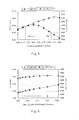
- the relation between the stiffness R (kgf/mm) and the critical revolution number min-Ncr (rpm) of the disc-shaped tool about the position in the radius direction of the central concentric circle located in the center of the two concentric circles forming the virtual region was obtained by finite element model (FEM) analysis using a computer.
- FEM finite element model
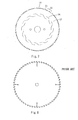
- the stiffness R As reference values of the stiffness R and the critical revolution number, the stiffness R of 0.59 kgf/mm or more and critical revolution number of 4,430 rpm or more, which are values of a circular saw blade having no slit in a conventional base metal as shown in FIG. 8 (having four slits on the outer periphery) were employed.
- the stiffness R As shown in FIG. 3, in the case where the position of the central concentric circle was over 0.6r, the stiffness R was higher than the reference value. In the case where the position of the central concentric circle was below 0.8r, the critical revolution number was higher than the reference value. Therefore, the position of the central concentric circle was specified to be in a range of 0.6r to 0.8r.
- the ratio of the length of an arc in the virtual region of the central concentric circle with respect to the interval of the two concentric circles in the virtual region was obtained in the case where the position of the central concentric circle was 0.8r and 0.6r.
- the ratio of the critical revolution number needs to be over 3 although there is no problem in the stiffness R as shown in Fig.4.
- the ratio of the stiffness R needs to be below 6 as shown in FIG. 5 and there is no problem in the critical revolution number.
- the ratio of the length of the arc with respect to the interval of the concentric circles was specified to be in a range of 3 to 6.
- the stiffness R has no problem if the overlapping angle is equal to or less than 12° and the critical revolution number is equal to or more than -1° as shown in Fig.6. Further, considering an analysis result in the case where the position of the central concentric circle is 0.6r and 0.8r, the overlapping angle was specified to be in a range of 0° to 12°.
- the stiffness of the circular saw blade drops so that four or more virtual regions are required. Even if the quantity of the virtual regions exceeds 24, the characteristic does not change so much, thereby increasing cost for forming the slit. Further if the minimum neighborhood distance of adjoining slits is smaller than 0.05r or smaller than 0.08r under a specific severe condition, an interval between the slits is likely to be short-circuited, so that there is a fear that the circular saw blade may be damaged easily.
- the plurality of virtual regions can be formed into the same shape.
- the symmetrical property in the rotation direction of the circular saw blade is secured, thereby raising productivity and improving visual aesthetic sense.
- the plurality of virtual regions can be formed into the same shape but also the slits formed in the plurality of virtual regions can be formed into the same shape. Because the plurality of virtual regions is formed into the same shape and the slits formed in the plurality of virtual regions are formed into the same shape, the symmetrical property in the rotation direction of the circular saw blade is secured, thereby further raising productivity and improving visual aesthetic sense.
- the present invention can suppress generation of noise and vibration which affects the quality of a cut face adversely while maintaining stiffness and critical revolution number equal to or higher than a conventional circular saw blade and securing a high durability. Further, because the plurality of virtual regions is formed into the same shape and the slits in the respective virtual regions are formed into the same shape, the symmetrical property in the rotation direction of the disk-shaped tool is secured, thereby raising productivity and improving a visual aesthetic sense.
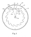
- FIG. 1 is a side view showing a circular saw blade for cutting aluminum according to the embodiment of the present invention.
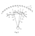
- FIG. 2 is a partially enlarged side view showing a major portion of the circular saw blade.
- the circular saw blade 10 is provided with a disc-shaped base metal 11 and teeth 12.
- the teeth 12 are protruded outwardly from plural positions continuously disposed at an equal interval on an outer periphery of the base metal 11.
- the base metal 11 has a central shaft hole 11a and outer periphery slits 11b which extend slightly from the outer periphery of each gullet bottom at six positions disposed at an equal interval in a circumferential direction while rounded in the shape of an arc internally.
- the base metal 11 contains fourteen virtual regions 13 which are formed by two radius lines 13a, 13b extending from a rotation center thereof and two concentric circles 13c, 13d on the base metal formed around the rotation center, the virtual regions 13 being provided continuously around the rotation center.
- Each of the virtual regions 13 contains a single slit 14 which makes contact with the two radius lines 13a and 13b and the two concentric circles 13c and 13d, the single slit 14 being formed by laser processing or the like.
- a central angle formed by the two radius lines around the rotation center is substantially 34° and is divided in terms of the central angle into three sections, forward small-diameter portion 14a, central inclined portion 14b and rearward large-diameter portion 14c, which are formed continuously as viewed from the forward side in the rotation direction.
- a radius of the forward small-diameter portion 14a is substantially 0. 64r and a radius of the rearward large diameter portion 14c is substantially 0.76r.
- "r” indicates a radius of a maximum gullet bottom radius of the base metal 11, that is, a radius from the center of the base metal to a root of the tooth 12.
- the central inclined portion 14b is disposed obliquely between the forward small-diameter portion 14a and the rearward large-diameter portion 14c and a joint portion which is a boundary between the forward small-diameter portion 14a and the rearward large-diameter portion 14c is formed into an arc shape.
- the position of the central concentric circle 13e in the radius direction (position in the radius direction) located in the center of an interval between the two concentric circles 13c and 13d forming the virtual region 13 is 0.7r.
- Overlapping of the continuously adjoining virtual regions 13 has a central angle ⁇ s of about 8.29° which is an angle around the rotation center.
- the minimum neighborhood distance between the adjoining slits 14 is about 0.1r.
- the ratio (slit horizontal to vertical ratio) of the length of an arc of 0.415r within the virtual region 13 of the central concentric circle 13e with respect to an interval between the two concentric circles in each one of the virtual regions 13 of 0.104r is about 3.99.
- the arrangement position and condition of the slit 14 to be provided in the circular saw blade 10 are specified within the above-described numeric range.
- the embodiment can raise the durability and suppress generation of noise and vibration affecting the quality of a cut face adversely while holding a stiffness and critical revolution number characteristic which are equivalent to or higher than a conventional circular saw blade having no slit in its base metal.
- the slit 14 formed within each one of the virtual regions 13 is formed into the same shape as well as the shape of each of the plurality of virtual regions 13 is formed into the same shape, a symmetrical property in the rotation direction of the circular saw blade 10 is secured and productivity and visual aesthetic sense are intensified.
- the plurality of virtual regions does not always need to have the same shape or the shape of the slit does not always need to be identical.
- a circular saw blade 20 of the modification is so constructed that as shown in FIG. 7, four teeth 22 arranged at an equal interval of one pitch continuously and a tooth 23 shifted by a 1.5 pitch from this are projected as a combination outwardly in the diameter direction from a plurality of positions of the outer periphery of a disc-shaped base metal 21.
- the quantity of the teeth 22 arranged at the equal interval may be three or five although it is most preferred to be four.
- the configuration of the slit 24 formed on the base metal 21 and the virtual region (not shown) are the same as the slit 14 and the virtual region 13 of the above embodiment.
- the circular saw blade 20 of the modification secures the same effect as the above embodiment by providing with the predetermined slits 24 and it has been made evident that including one tooth 23 shifted in pitch in the plurality of teeth 22 arranged at the equal pitch is very effective for cutting a metal pipe such as steel and iron.
- test pieces 1 for cutting aluminum material of the embodiment and test pieces 2 for cutting steel/iron of the modification were prepared.
- the test pieces 1 are circular saw blades based on three kinds of specifications (outside diameter ⁇ tooth thickness ⁇ base metal thickness ⁇ central hole diameter ⁇ number of teeth) 1 to 3 having the above-described slit structure as shown in Table 1 below, these circular saw blades having six outer periphery slits extending by 10 mm from the outer periphery to the rotation center.
- the cutting condition is a revolution number N and a feeding speed F, which is different for each one of the circular saw blades.
- An object material to be cut is aluminum extruded material A6063.
- the test pieces 2 are circular saw blades based on two kinds of specifications 1, 2 having the above described slit structure (outside diameter ⁇ tooth thickness ⁇ base metal thickness ⁇ central hole diameter ⁇ number of teeth) and have no slits on the outer periphery.
- the cutting condition is a revolution number N and a feeding speed F, which are common.
- the object materials to be cut are respective kinds of steel pipes, STKM13C, 15A, and 15B.
- the result of the experiment shows the durability of both the test pieces 1 and 2 is raised by about 1. 5 times as compared with a conventional circular saw blade shown in FIG. 8. That is, this is a result produced because the stiffness and the critical revolution number of the test pieces are raised as compared with those of a conventional product. Because the critical revolution number is raised, vibration accompanying a cutting work is suppressed more as compared with the conventional product, thereby suppressing generation of noise and raising the processing accuracy on a cutting face.
- the gullet bottom of the circular saw blade is formed uniformly, the gullet bottom may be ununiform and in that case, as the value of r, the maximum gullet bottom radius is used.
- generation of vibration is intended to be suppressed while maintaining the stiffness and critical revolution number appropriately by specifying the slit to be provided in the circular saw blade.
- Such a slit specifying condition is not restricted to the circular saw blade but applied to other disc-shaped rotation cutting tool, for example, disc cutting grinding stone, circular slitter knife and the like.
- the present invention is very advantageous for design or the like of a disk-shaped tool in that the arrangement position and the entire shape of the slit formed in the disc-shaped tool is defined, thereby raising the stiffness and the critical revolution number of the disc-shaped tool, such that generation of vibration can be suppressed.
Landscapes
- Engineering & Computer Science (AREA)
- Mechanical Engineering (AREA)
- Life Sciences & Earth Sciences (AREA)
- Wood Science & Technology (AREA)
- Forests & Forestry (AREA)
- Sawing (AREA)
- Milling Processes (AREA)
- Adhesive Tapes (AREA)
- Holding Or Fastening Of Disk On Rotational Shaft (AREA)
- Dental Tools And Instruments Or Auxiliary Dental Instruments (AREA)
- Gears, Cams (AREA)
- Food-Manufacturing Devices (AREA)
Applications Claiming Priority (2)
| Application Number | Priority Date | Filing Date | Title |
|---|---|---|---|
| JP2003358421A JP4136893B2 (ja) | 2003-10-17 | 2003-10-17 | 円盤状工具 |
| PCT/JP2004/015350 WO2005037503A1 (fr) | 2003-10-17 | 2004-10-12 | Outil circulaire |
Publications (3)
| Publication Number | Publication Date |
|---|---|
| EP1679165A1 true EP1679165A1 (fr) | 2006-07-12 |
| EP1679165A4 EP1679165A4 (fr) | 2007-09-12 |
| EP1679165B1 EP1679165B1 (fr) | 2009-04-15 |
Family
ID=34463299
Family Applications (1)
| Application Number | Title | Priority Date | Filing Date |
|---|---|---|---|
| EP04792519A Expired - Lifetime EP1679165B1 (fr) | 2003-10-17 | 2004-10-12 | Outil circulaire |
Country Status (14)
| Country | Link |
|---|---|
| US (1) | US8042443B2 (fr) |
| EP (1) | EP1679165B1 (fr) |
| JP (1) | JP4136893B2 (fr) |
| KR (1) | KR101041312B1 (fr) |
| CN (1) | CN100469501C (fr) |
| AT (1) | ATE428547T1 (fr) |
| AU (1) | AU2004282051A1 (fr) |
| BR (1) | BRPI0415439B1 (fr) |
| CA (1) | CA2542470C (fr) |
| DE (1) | DE602004020648D1 (fr) |
| NO (1) | NO333385B1 (fr) |
| RU (1) | RU2348513C2 (fr) |
| TW (1) | TW200533445A (fr) |
| WO (1) | WO2005037503A1 (fr) |
Cited By (2)
| Publication number | Priority date | Publication date | Assignee | Title |
|---|---|---|---|---|
| WO2008135035A1 (fr) * | 2007-05-08 | 2008-11-13 | Leitz Gmbh & Co. Kg | Outil d'usinage par enlèvement de copeaux, en particulier lame de scie circulaire |
| US10279407B2 (en) | 2015-10-30 | 2019-05-07 | Black & Decker Inc. | Circular saw blades |
Families Citing this family (13)
| Publication number | Priority date | Publication date | Assignee | Title |
|---|---|---|---|---|
| US9463518B2 (en) | 2011-01-31 | 2016-10-11 | Black & Decker Inc. | Saw blade with reduced modal frequencies in the operating frequency range |
| US9475141B2 (en) | 2011-08-04 | 2016-10-25 | Milwaukee Electric Tool Corporation | Reciprocating saw blade |
| USD688543S1 (en) | 2012-03-20 | 2013-08-27 | Milwaukee Electric Tool Corporation | Saw blade |
| WO2015065099A1 (fr) * | 2013-11-01 | 2015-05-07 | 주식회사 포스코 | Tampon anti-vibration et scie circulaire le comprenant, et appareil de coupe d'une plaque en métal |
| USD729600S1 (en) | 2014-05-06 | 2015-05-19 | Milwaukee Electric Tool Corporation | Saw blade |
| JP2016209950A (ja) * | 2015-05-07 | 2016-12-15 | 兼房株式会社 | 丸鋸および丸鋸による加工方法 |
| USD813635S1 (en) | 2016-12-13 | 2018-03-27 | Black & Decker Inc. | Circular saw blade |
| EP4008467A4 (fr) * | 2019-08-01 | 2022-10-12 | Sul Corte Importadora de Ferramentas Ltda. | Scie circulaire à pastilles rapportées et procédé de fabrication d'une scie circulaire à pastilles rapportées |
| CN112705788A (zh) * | 2019-10-25 | 2021-04-27 | 浙江科诚工具有限公司 | 一种高效冷锯圆锯片 |
| RU2736994C1 (ru) * | 2020-03-19 | 2020-11-23 | Федеральное государственное автономное образовательное учреждение высшего образования «Северный (Арктический) федеральный университет имени М. В. Ломоносова» | Круглая пила |
| WO2023047756A1 (fr) | 2021-09-23 | 2023-03-30 | 兼房株式会社 | Outil rotatif en forme de disque |
| WO2025121018A1 (fr) | 2023-12-04 | 2025-06-12 | 兼房株式会社 | Outil rotatif discoïde |
| WO2025121078A1 (fr) * | 2023-12-08 | 2025-06-12 | 兼房株式会社 | Lame de scie circulaire |
Family Cites Families (29)
| Publication number | Priority date | Publication date | Assignee | Title |
|---|---|---|---|---|
| US212813A (en) * | 1879-03-04 | Improvement in circular saws | ||
| US714359A (en) * | 1902-04-07 | 1902-11-25 | John Brooks | Disk cutter. |
| US1083645A (en) * | 1912-09-23 | 1914-01-06 | Jacob Wettstein | Circular saw-blade. |
| JPS49106683A (fr) * | 1973-02-16 | 1974-10-09 | ||
| SU484988A1 (ru) * | 1973-12-03 | 1975-09-25 | Дискова пила | |
| DE2623339C2 (de) * | 1976-05-25 | 1982-02-25 | Ernst Prof. Dr.-Ing. 2106 Bendestorf Salje | Kreissägeblatt |
| SU802020A1 (ru) * | 1979-08-08 | 1981-02-07 | Кировский Политехнический Институт | Кругла дискова пила |
| US5182976A (en) * | 1983-09-09 | 1993-02-02 | The Peerless Saw Company | Spring beamed shock absorbing circular saw blade body |
| US4776251A (en) * | 1987-06-12 | 1988-10-11 | Pacific Saw And Knife Company | Circular saw blade with circumferentally extending laser-cut slots |
| JPH069765Y2 (ja) * | 1987-06-18 | 1994-03-16 | 株式会社オリオン工具製作所 | 回 転 鋸 |
| DE68916930T2 (de) * | 1988-12-27 | 1994-12-01 | Osaka Diamond Ind | Träger für ein Sägeblatt. |
| SU1708614A1 (ru) | 1990-04-10 | 1992-01-30 | Центральный научно-исследовательский институт механической обработки древесины | Кругла пила |
| JP2556943B2 (ja) | 1991-07-08 | 1996-11-27 | ミサワホーム株式会社 | ユニット及びパネルの組み合わせ工法 |
| RU2048286C1 (ru) * | 1992-04-15 | 1995-11-20 | Центральный научно-исследовательский институт механической обработки древесины Всероссийского научно-производственного объединения "Научдревпром" | Круглая пила |
| JPH069765A (ja) | 1992-04-30 | 1994-01-18 | Mitsubishi Rayon Co Ltd | 熱収縮性ポリエステルフィルム |
| JP3312389B2 (ja) | 1992-07-07 | 2002-08-05 | 東レ株式会社 | セラミックス・グリーンシートおよびその現像方法 |
| JPH0624824U (ja) * | 1992-08-28 | 1994-04-05 | オタリ株式会社 | 丸 鋸 |
| JPH0733533A (ja) | 1993-06-28 | 1995-02-03 | Lion Corp | セラミックグリーンシート用添加剤 |
| DE4328482C2 (de) | 1993-08-24 | 1998-01-29 | Fgw Forsch Werkzeuge Werkstoff | Kreissägeblatt |
| JPH0733533U (ja) * | 1993-12-06 | 1995-06-20 | 津根精機株式会社 | 丸 鋸 |
| US5555788A (en) * | 1995-03-29 | 1996-09-17 | Credo Tool Company | Saw blade |
| AU675404B3 (en) * | 1996-09-04 | 1997-01-30 | Canton (Australia) Pty. Limited | Noise abatemant superhard material impregnated saw |
| DE19648129A1 (de) | 1996-11-21 | 1998-05-28 | Lauffer Adelbert Dipl Ing Fh | Kreissägeblatt |
| DE19822742A1 (de) * | 1998-05-20 | 1999-11-25 | Arntz Joh Wilh Fa | Kreisscheibenförmiges Werkzeug |
| AU2325300A (en) | 1999-02-05 | 2000-08-25 | Toyama Chemical Co. Ltd. | Tricyclic quinolonecarboxylic acid derivatives or salts thereof |
| US20030056633A1 (en) * | 2001-09-26 | 2003-03-27 | Baron Kevin Frank | Cutting disc core with noise reduction |
| CN2504023Y (zh) * | 2001-09-29 | 2002-08-07 | 华中科技大学 | 激光切缝金刚石消音圆锯片 |
| JP4241177B2 (ja) * | 2003-05-09 | 2009-03-18 | セイコーエプソン株式会社 | 液体噴射装置 |
| EP1570936A1 (fr) * | 2004-03-05 | 2005-09-07 | Shinhan Diamond Industrial Co., Ltd. | Disque de coupe à ébauches et méthode de fabrication associée |
-
2003
- 2003-10-17 JP JP2003358421A patent/JP4136893B2/ja not_active Expired - Lifetime
-
2004
- 2004-10-12 AT AT04792519T patent/ATE428547T1/de not_active IP Right Cessation
- 2004-10-12 AU AU2004282051A patent/AU2004282051A1/en not_active Abandoned
- 2004-10-12 CN CNB2004800302843A patent/CN100469501C/zh not_active Expired - Lifetime
- 2004-10-12 CA CA 2542470 patent/CA2542470C/fr not_active Expired - Lifetime
- 2004-10-12 DE DE200460020648 patent/DE602004020648D1/de not_active Expired - Lifetime
- 2004-10-12 BR BRPI0415439A patent/BRPI0415439B1/pt active IP Right Grant
- 2004-10-12 EP EP04792519A patent/EP1679165B1/fr not_active Expired - Lifetime
- 2004-10-12 RU RU2006116881A patent/RU2348513C2/ru active
- 2004-10-12 WO PCT/JP2004/015350 patent/WO2005037503A1/fr not_active Ceased
- 2004-10-12 US US10/575,479 patent/US8042443B2/en not_active Expired - Lifetime
- 2004-10-12 KR KR1020067007055A patent/KR101041312B1/ko not_active Expired - Fee Related
- 2004-10-15 TW TW93131341A patent/TW200533445A/zh not_active IP Right Cessation
-
2006
- 2006-05-16 NO NO20062205A patent/NO333385B1/no unknown
Cited By (2)
| Publication number | Priority date | Publication date | Assignee | Title |
|---|---|---|---|---|
| WO2008135035A1 (fr) * | 2007-05-08 | 2008-11-13 | Leitz Gmbh & Co. Kg | Outil d'usinage par enlèvement de copeaux, en particulier lame de scie circulaire |
| US10279407B2 (en) | 2015-10-30 | 2019-05-07 | Black & Decker Inc. | Circular saw blades |
Also Published As
| Publication number | Publication date |
|---|---|
| US20070056426A1 (en) | 2007-03-15 |
| AU2004282051A1 (en) | 2005-04-28 |
| KR101041312B1 (ko) | 2011-06-14 |
| BRPI0415439B1 (pt) | 2017-03-14 |
| DE602004020648D1 (de) | 2009-05-28 |
| TWI316882B (fr) | 2009-11-11 |
| RU2348513C2 (ru) | 2009-03-10 |
| CN100469501C (zh) | 2009-03-18 |
| WO2005037503A1 (fr) | 2005-04-28 |
| CA2542470A1 (fr) | 2005-04-28 |
| BRPI0415439A (pt) | 2006-12-05 |
| US8042443B2 (en) | 2011-10-25 |
| EP1679165B1 (fr) | 2009-04-15 |
| NO20062205L (no) | 2006-05-16 |
| EP1679165A4 (fr) | 2007-09-12 |
| RU2006116881A (ru) | 2007-11-27 |
| JP2005119205A (ja) | 2005-05-12 |
| KR20060125724A (ko) | 2006-12-06 |
| ATE428547T1 (de) | 2009-05-15 |
| CN1867432A (zh) | 2006-11-22 |
| NO333385B1 (no) | 2013-05-21 |
| JP4136893B2 (ja) | 2008-08-20 |
| CA2542470C (fr) | 2011-07-19 |
| TW200533445A (en) | 2005-10-16 |
Similar Documents
| Publication | Publication Date | Title |
|---|---|---|
| EP1679165B1 (fr) | Outil circulaire | |
| JP5108106B2 (ja) | スローアウェイ式切削回転工具 | |
| EP0932470B1 (fr) | Lame de scie circulaire a echancrures | |
| JP5198579B2 (ja) | スローアウェイ式切削回転工具 | |
| CA2605392A1 (fr) | Lame de scie | |
| WO2004112998A8 (fr) | Decoupeur de trou pour tole metallique | |
| CA2413600A1 (fr) | Outil en forme de disque, notamment, lame de scie circulaire | |
| US20040065183A1 (en) | Disk cutter | |
| JP5426555B2 (ja) | スローアウェイ式切削回転工具 | |
| JP5397251B2 (ja) | チップソー及びそれを備えた電動工具 | |
| EP0343983B1 (fr) | Procédé et dispositif pour meuler les dents d'un outil coupant | |
| JP4164708B2 (ja) | 丸鋸 | |
| JP5426572B2 (ja) | スローアウェイ式切削回転工具 | |
| KR20170088093A (ko) | 금속절삭용 원형톱 | |
| CN216780358U (zh) | 一种剖沟刀具 | |
| CN222154145U (zh) | 一种锯片 | |
| JP2025101117A (ja) | スローアウェイ式スカラップカッッター | |
| KR20110129050A (ko) | 스크라이빙 휠 및 그 제조방법 | |
| JP2005022416A (ja) | チップソー及びその製造方法 | |
| JP2017104966A (ja) | チップソー及びその製造方法 | |
| JPH0737528U (ja) | 金属切断用チップソー | |
| CN110802752A (zh) | 一种玻璃切割刀及其加工方法 | |
| JPH06659U (ja) | 切断砥石 | |
| JPS61241018A (ja) | 鋸刃 | |
| JPH0560717U (ja) | 工作機械用切削工具 |
Legal Events
| Date | Code | Title | Description |
|---|---|---|---|
| PUAI | Public reference made under article 153(3) epc to a published international application that has entered the european phase |
Free format text: ORIGINAL CODE: 0009012 |
|
| 17P | Request for examination filed |
Effective date: 20060511 |
|
| AK | Designated contracting states |
Kind code of ref document: A1 Designated state(s): AT BE BG CH CY CZ DE DK EE ES FI FR GB GR HU IE IT LI LU MC NL PL PT RO SE SI SK TR |
|
| AX | Request for extension of the european patent |
Extension state: AL HR LT LV MK |
|
| A4 | Supplementary search report drawn up and despatched |
Effective date: 20070814 |
|
| RIC1 | Information provided on ipc code assigned before grant |
Ipc: B23D 61/02 20060101ALI20070808BHEP Ipc: B27B 33/08 20060101AFI20050504BHEP |
|
| GRAP | Despatch of communication of intention to grant a patent |
Free format text: ORIGINAL CODE: EPIDOSNIGR1 |
|
| GRAS | Grant fee paid |
Free format text: ORIGINAL CODE: EPIDOSNIGR3 |
|
| GRAA | (expected) grant |
Free format text: ORIGINAL CODE: 0009210 |
|
| AK | Designated contracting states |
Kind code of ref document: B1 Designated state(s): AT BE BG CH CY CZ DE DK EE ES FI FR GB GR HU IE IT LI LU MC NL PL PT RO SE SI SK TR |
|
| AX | Request for extension of the european patent |
Extension state: AL HR LT LV MK |
|
| REG | Reference to a national code |
Ref country code: GB Ref legal event code: FG4D Ref country code: CH Ref legal event code: EP |
|
| REG | Reference to a national code |
Ref country code: IE Ref legal event code: FG4D |
|
| REF | Corresponds to: |
Ref document number: 602004020648 Country of ref document: DE Date of ref document: 20090528 Kind code of ref document: P |
|
| REG | Reference to a national code |
Ref country code: SE Ref legal event code: TRGR |
|
| LTIE | Lt: invalidation of european patent or patent extension |
Effective date: 20090415 |
|
| NLV1 | Nl: lapsed or annulled due to failure to fulfill the requirements of art. 29p and 29m of the patents act | ||
| PG25 | Lapsed in a contracting state [announced via postgrant information from national office to epo] |
Ref country code: PT Free format text: LAPSE BECAUSE OF FAILURE TO SUBMIT A TRANSLATION OF THE DESCRIPTION OR TO PAY THE FEE WITHIN THE PRESCRIBED TIME-LIMIT Effective date: 20090915 Ref country code: FI Free format text: LAPSE BECAUSE OF FAILURE TO SUBMIT A TRANSLATION OF THE DESCRIPTION OR TO PAY THE FEE WITHIN THE PRESCRIBED TIME-LIMIT Effective date: 20090415 Ref country code: ES Free format text: LAPSE BECAUSE OF FAILURE TO SUBMIT A TRANSLATION OF THE DESCRIPTION OR TO PAY THE FEE WITHIN THE PRESCRIBED TIME-LIMIT Effective date: 20090726 Ref country code: AT Free format text: LAPSE BECAUSE OF FAILURE TO SUBMIT A TRANSLATION OF THE DESCRIPTION OR TO PAY THE FEE WITHIN THE PRESCRIBED TIME-LIMIT Effective date: 20090415 |
|
| PG25 | Lapsed in a contracting state [announced via postgrant information from national office to epo] |
Ref country code: NL Free format text: LAPSE BECAUSE OF FAILURE TO SUBMIT A TRANSLATION OF THE DESCRIPTION OR TO PAY THE FEE WITHIN THE PRESCRIBED TIME-LIMIT Effective date: 20090415 Ref country code: PL Free format text: LAPSE BECAUSE OF FAILURE TO SUBMIT A TRANSLATION OF THE DESCRIPTION OR TO PAY THE FEE WITHIN THE PRESCRIBED TIME-LIMIT Effective date: 20090415 Ref country code: SI Free format text: LAPSE BECAUSE OF FAILURE TO SUBMIT A TRANSLATION OF THE DESCRIPTION OR TO PAY THE FEE WITHIN THE PRESCRIBED TIME-LIMIT Effective date: 20090415 |
|
| PG25 | Lapsed in a contracting state [announced via postgrant information from national office to epo] |
Ref country code: EE Free format text: LAPSE BECAUSE OF FAILURE TO SUBMIT A TRANSLATION OF THE DESCRIPTION OR TO PAY THE FEE WITHIN THE PRESCRIBED TIME-LIMIT Effective date: 20090415 Ref country code: DK Free format text: LAPSE BECAUSE OF FAILURE TO SUBMIT A TRANSLATION OF THE DESCRIPTION OR TO PAY THE FEE WITHIN THE PRESCRIBED TIME-LIMIT Effective date: 20090415 Ref country code: CZ Free format text: LAPSE BECAUSE OF FAILURE TO SUBMIT A TRANSLATION OF THE DESCRIPTION OR TO PAY THE FEE WITHIN THE PRESCRIBED TIME-LIMIT Effective date: 20090415 Ref country code: RO Free format text: LAPSE BECAUSE OF FAILURE TO SUBMIT A TRANSLATION OF THE DESCRIPTION OR TO PAY THE FEE WITHIN THE PRESCRIBED TIME-LIMIT Effective date: 20090415 |
|
| PLBE | No opposition filed within time limit |
Free format text: ORIGINAL CODE: 0009261 |
|
| STAA | Information on the status of an ep patent application or granted ep patent |
Free format text: STATUS: NO OPPOSITION FILED WITHIN TIME LIMIT |
|
| PG25 | Lapsed in a contracting state [announced via postgrant information from national office to epo] |
Ref country code: BE Free format text: LAPSE BECAUSE OF FAILURE TO SUBMIT A TRANSLATION OF THE DESCRIPTION OR TO PAY THE FEE WITHIN THE PRESCRIBED TIME-LIMIT Effective date: 20090415 Ref country code: SK Free format text: LAPSE BECAUSE OF FAILURE TO SUBMIT A TRANSLATION OF THE DESCRIPTION OR TO PAY THE FEE WITHIN THE PRESCRIBED TIME-LIMIT Effective date: 20090415 |
|
| 26N | No opposition filed |
Effective date: 20100118 |
|
| PG25 | Lapsed in a contracting state [announced via postgrant information from national office to epo] |
Ref country code: BG Free format text: LAPSE BECAUSE OF FAILURE TO SUBMIT A TRANSLATION OF THE DESCRIPTION OR TO PAY THE FEE WITHIN THE PRESCRIBED TIME-LIMIT Effective date: 20090715 |
|
| PG25 | Lapsed in a contracting state [announced via postgrant information from national office to epo] |
Ref country code: MC Free format text: LAPSE BECAUSE OF NON-PAYMENT OF DUE FEES Effective date: 20091031 |
|
| REG | Reference to a national code |
Ref country code: CH Ref legal event code: PL |
|
| REG | Reference to a national code |
Ref country code: IE Ref legal event code: MM4A |
|
| REG | Reference to a national code |
Ref country code: FR Ref legal event code: ST Effective date: 20100630 |
|
| PG25 | Lapsed in a contracting state [announced via postgrant information from national office to epo] |
Ref country code: FR Free format text: LAPSE BECAUSE OF NON-PAYMENT OF DUE FEES Effective date: 20091102 |
|
| PG25 | Lapsed in a contracting state [announced via postgrant information from national office to epo] |
Ref country code: CH Free format text: LAPSE BECAUSE OF NON-PAYMENT OF DUE FEES Effective date: 20091031 Ref country code: LI Free format text: LAPSE BECAUSE OF NON-PAYMENT OF DUE FEES Effective date: 20091031 Ref country code: IE Free format text: LAPSE BECAUSE OF NON-PAYMENT OF DUE FEES Effective date: 20091012 Ref country code: GR Free format text: LAPSE BECAUSE OF FAILURE TO SUBMIT A TRANSLATION OF THE DESCRIPTION OR TO PAY THE FEE WITHIN THE PRESCRIBED TIME-LIMIT Effective date: 20090716 |
|
| PG25 | Lapsed in a contracting state [announced via postgrant information from national office to epo] |
Ref country code: LU Free format text: LAPSE BECAUSE OF NON-PAYMENT OF DUE FEES Effective date: 20091012 |
|
| PG25 | Lapsed in a contracting state [announced via postgrant information from national office to epo] |
Ref country code: HU Free format text: LAPSE BECAUSE OF FAILURE TO SUBMIT A TRANSLATION OF THE DESCRIPTION OR TO PAY THE FEE WITHIN THE PRESCRIBED TIME-LIMIT Effective date: 20091016 |
|
| PG25 | Lapsed in a contracting state [announced via postgrant information from national office to epo] |
Ref country code: TR Free format text: LAPSE BECAUSE OF FAILURE TO SUBMIT A TRANSLATION OF THE DESCRIPTION OR TO PAY THE FEE WITHIN THE PRESCRIBED TIME-LIMIT Effective date: 20090415 |
|
| PG25 | Lapsed in a contracting state [announced via postgrant information from national office to epo] |
Ref country code: CY Free format text: LAPSE BECAUSE OF FAILURE TO SUBMIT A TRANSLATION OF THE DESCRIPTION OR TO PAY THE FEE WITHIN THE PRESCRIBED TIME-LIMIT Effective date: 20090415 |
|
| PGFP | Annual fee paid to national office [announced via postgrant information from national office to epo] |
Ref country code: GB Payment date: 20231020 Year of fee payment: 20 |
|
| PGFP | Annual fee paid to national office [announced via postgrant information from national office to epo] |
Ref country code: SE Payment date: 20231019 Year of fee payment: 20 Ref country code: IT Payment date: 20231026 Year of fee payment: 20 Ref country code: DE Payment date: 20231020 Year of fee payment: 20 |
|
| REG | Reference to a national code |
Ref country code: DE Ref legal event code: R071 Ref document number: 602004020648 Country of ref document: DE |
|
| REG | Reference to a national code |
Ref country code: GB Ref legal event code: PE20 Expiry date: 20241011 |
|
| REG | Reference to a national code |
Ref country code: SE Ref legal event code: EUG |
|
| PG25 | Lapsed in a contracting state [announced via postgrant information from national office to epo] |
Ref country code: GB Free format text: LAPSE BECAUSE OF EXPIRATION OF PROTECTION Effective date: 20241011 |
|
| PG25 | Lapsed in a contracting state [announced via postgrant information from national office to epo] |
Ref country code: GB Free format text: LAPSE BECAUSE OF EXPIRATION OF PROTECTION Effective date: 20241011 |