EP1689622B1 - Mecanisme de rappel de ceintures de securite - Google Patents
Mecanisme de rappel de ceintures de securite Download PDFInfo
- Publication number
- EP1689622B1 EP1689622B1 EP04797039A EP04797039A EP1689622B1 EP 1689622 B1 EP1689622 B1 EP 1689622B1 EP 04797039 A EP04797039 A EP 04797039A EP 04797039 A EP04797039 A EP 04797039A EP 1689622 B1 EP1689622 B1 EP 1689622B1
- Authority
- EP
- European Patent Office
- Prior art keywords
- belt
- actuator
- retraction mechanism
- cam member
- pawl
- Prior art date
- Legal status (The legal status is an assumption and is not a legal conclusion. Google has not performed a legal analysis and makes no representation as to the accuracy of the status listed.)
- Expired - Lifetime
Links
- 230000007246 mechanism Effects 0.000 title claims abstract description 55
- 238000010276 construction Methods 0.000 claims description 2
- 230000000717 retained effect Effects 0.000 claims description 2
- 230000009471 action Effects 0.000 description 4
- 230000008901 benefit Effects 0.000 description 2
- 238000006467 substitution reaction Methods 0.000 description 2
- 230000008859 change Effects 0.000 description 1
- 230000004048 modification Effects 0.000 description 1
- 238000012986 modification Methods 0.000 description 1
- 230000008707 rearrangement Effects 0.000 description 1
Images

Classifications
-
- B—PERFORMING OPERATIONS; TRANSPORTING
- B60—VEHICLES IN GENERAL
- B60R—VEHICLES, VEHICLE FITTINGS, OR VEHICLE PARTS, NOT OTHERWISE PROVIDED FOR
- B60R22/00—Safety belts or body harnesses in vehicles
- B60R22/34—Belt retractors, e.g. reels
- B60R22/347—Belt retractors, e.g. reels with means for permanently locking the retractor during the wearing of the belt
-
- B—PERFORMING OPERATIONS; TRANSPORTING
- B60—VEHICLES IN GENERAL
- B60N—SEATS SPECIALLY ADAPTED FOR VEHICLES; VEHICLE PASSENGER ACCOMMODATION NOT OTHERWISE PROVIDED FOR
- B60N2/00—Seats specially adapted for vehicles; Arrangement or mounting of seats in vehicles
- B60N2/24—Seats specially adapted for vehicles; Arrangement or mounting of seats in vehicles for particular purposes or particular vehicles
- B60N2/26—Seats specially adapted for vehicles; Arrangement or mounting of seats in vehicles for particular purposes or particular vehicles for children
- B60N2/265—Adaptations for seat belts
-
- B—PERFORMING OPERATIONS; TRANSPORTING
- B60—VEHICLES IN GENERAL
- B60R—VEHICLES, VEHICLE FITTINGS, OR VEHICLE PARTS, NOT OTHERWISE PROVIDED FOR
- B60R22/00—Safety belts or body harnesses in vehicles
- B60R22/34—Belt retractors, e.g. reels
- B60R22/347—Belt retractors, e.g. reels with means for permanently locking the retractor during the wearing of the belt
- B60R2022/3475—Belt retractors, e.g. reels with means for permanently locking the retractor during the wearing of the belt having means for acting directly upon the belt, e.g. by clamping or friction
-
- B—PERFORMING OPERATIONS; TRANSPORTING
- B60—VEHICLES IN GENERAL
- B60R—VEHICLES, VEHICLE FITTINGS, OR VEHICLE PARTS, NOT OTHERWISE PROVIDED FOR
- B60R22/00—Safety belts or body harnesses in vehicles
- B60R22/10—Safety belts or body harnesses in vehicles specially adapted for children or animals
- B60R22/105—Safety belts or body harnesses in vehicles specially adapted for children or animals for children
Definitions
- the present invention relates to a belt retraction mechanism.
- a belt retraction mechanism Such a device is known, for example, from CH374899 which discloses a spring-loaded spool for the retraction of a belt, and a releasable racket and pawl arrangement for preventing undesirable withdrawal of the belt.
- a locking disk and pin arrangement is proposed which serves to prevent both retraction and withdrawal of the belt when engaged.
- the present invention relates to a seat belt retraction mechanism for a child restraint seat.
- Fig. 1 shows a seat belt retractor 100 having a spool 110 biased to retract the belt in an anti-clockwise direction (direction of curved arrow).
- the teeth 120 of the ratchet 115 have a first generally front vertical face 121 and a rear sloped face 122. In the event of the belt being pulled from the retractor 100 (direction of straight arrow), the pawl 130 abuts against the vertical face 121 thus locking the belt against any movement from the retractor 100.
- the pawl 130 is first released from the ratchet 115 by an actuator thus allowing the spool 110 to rotate and the belt to be removed under tension from the spool 110.
- the belt retracts under tension and the pawl 130 is allowed to re-engage with the ratchet 115 and thus the child is suitably restrained.
- the pawl 130 will often engage with the intermediate rear sloped surface 122 of a tooth 120 between two adjacent vertical faces 121.
- the spool 110 will move clockwise until the pawl 130 positively engages and abuts against the next vertical face 121. This implies that there is a certain amount of belt that will travel out from the retractor 100 before the pawl 130 and ratchet 115 mechanism locks the belt.
- the present invention accordingly provides a belt retraction mechanism including:
- Combining a biased cam member that includes an engagement surface that locks the belt in position with a pawl and ratchet mechanism which prevents rotation of the spool provides an effective locking mechanism that locks the belt in place when the pawl and ratchet is engaged and the cam member is in the engagement position. Combining these features with an actuator which functions to release both of the separate locking means further results in a belt retraction mechanism that is convenient and easy to use.
- said pawl and ratchet mechanism reengages thereby preventing rotation of said spool.
- said cam member moves from said open position to said engagement position.
- said actuator includes biasing means to bias said actuator to said closed setting from said open setting on release of said actuator. This improves the safety of the belt retraction mechanism as the actuator is biased to a closed setting ensuring that the belt remains locked in position by default.
- said cam member is pivotable and includes a cam arm abutting said actuator, said cam arm located at an opposite end to said engagement surface, wherein on movement of said actuator to said open setting from said closed setting said cam member is caused to rotate from an engagement position to an open position.
- said engagement surface engages said belt by gripping said belt between said engagement surface and an inlet surface, said inlet surface forming part of an inlet for said seat belt retraction mechanism into which said belt is retracted.
- retraction of said belt causes said cam member to rotate to reduce the distance between said engagement surface and said inlet surface thereby causing said belt to be gripped more tightly.
- This further increases the safety aspects of the belt retraction mechanism as any sudden retraction of the belt such as would be encountered in an accident results in the belt being locked with greater force.
- said engagement surface includes a number of ridges or teeth to engage said belt.
- said actuator is retained in substantially linear slots to guide movement of said actuator when acting against said cam arm.
- said actuator further includes the pawl of said pawl and ratchet mechanism.
- said actuator and said pawl are of unitary construction.
- said actuator further includes a handle, said handle arranged to be operable from a location substantially opposite to said inlet of said belt retraction mechanism into which said belt is retracted.
- a handle By positioning the handle opposite to the inlet, one hand may be used to pull the belt from the belt retraction mechanism whilst the other hand operates the handle in a convenient and ergonomic position.
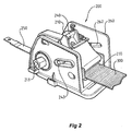
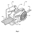
- a belt retraction mechanism 200 according to a preferred embodiment of the present invention. Whilst this embodiment is directly applicable to the harness of a child restraint or safety seat, the invention could equally be applied to other situations where a lockable belt retraction mechanism is required such as a safety harness for a seat or where belts are employed to secure goods whilst being stowed.
- Belt retraction mechanism 200 includes spool 210 upon which belt 300 is wound upon.
- Spool 210 is spring loaded by clockwork spring 212 which applies a rotating force in an anticlockwise direction as depicted in Fig. 3 thereby retracting belt 300 into inlet 270 when the spool 210 is released.
- clockwork spring 212 which applies a rotating force in an anticlockwise direction as depicted in Fig. 3 thereby retracting belt 300 into inlet 270 when the spool 210 is released.
- Equally other spring arrangements which bias the spool 210 to retract belt 300 such as a torsion spring or even resilient band arrangements are contemplated to be within the scope of the invention.
- a shaft (not shown) can be mounted to engage the hexagonal nut 213 thus allowing manual rotation of the spool to tighten the belt 300.
- Belt retraction mechanism 200 further includes actuator 240 mounted within housing 260 by protrusions 243 which slide in slots 262 located on each side of housing 260. Attached to actuator 240 is handle 250 which operates to move actuator 240 along slots 262.
- actuator 240 also includes pawl 241 which in one position engages with the teeth of ratchet 211 which are located on one side of spool 210 and oriented to block retraction of the belt 300 onto spool 210.
- Attached to actuator 240 at slot 242 is coil spring 280 whose other end is attached to housing cover 290 at mounting point 291.
- Coil spring 280 functions to bias pawl 241 into engagement with ratchet teeth 211.
- Abutting actuator 240 is pivotable cam member 220 which consists of an arm portion 222 and cam engagement surface 221 which includes a plurality of teeth or ridges to improve gripping.
- Cam member 220 is pivotable about an axis defined by bolt 224 which attaches cam member 220 to housing 260.
- a coil spring 230 is attached to an upper lip 223 of arm portion 222 and is attached at its opposite end to a slot 261 in housing 260.
- Coil spring 230 acts to bias the cam member 220 against actuator 240 when it is acting to release the cam member 220 and to further hold the cam engagement surface 221 against the belt 300 when there is clearance between the actuator 240 and cam member 220 to ensure that clamping of the belt occurs as soon as any withdrawal force is applied.
- other biasing means may be used in substitution for coil spring 230.
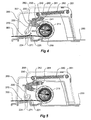
- handle 250 is pushed towards housing 260 causing actuator 240 to slide along slots 262 against the biasing action of both coil springs 230, 280 thereby releasing pawl 241 from ratchet 211 and furthermore pivoting cam member 220 so that the cam engagement surface 221 is moved away from the belt 300 thereby releasing the belt 300.
- pawl 241 is no longer preventing rotation of spool 210 and as belt 300 is free to move between cam engagement surface 221 and bottom surface 271, belt 300 will be retracted due to action of clockwork spring 212.
- the belt 300 can also be withdrawn thereby tensioning clockwork spring 212.
- cam member 220 under the action of coil spring 230 and without any opposing force from actuator 240 will return to an engagement position where engagement surface 221 will grip belt 300 to prevent removal. Furthermore, actuator 240 including pawl 241 will be drawn towards spool 210 along slots 262 to attempt to engage with ratchet teeth 211.
- cam member 220 moves to the engagement position a retraction force on the belt 300 will cause the cam member 220 to clamp the belt 300 virtually instantaneously.
- the clockwork spring 212 in spool 210 will have sufficient force to rotate in an anti-clockwise direction (as seen in Fig. 4 ) until pawl 241 engages with the next ratchet tooth 211.
- Belt 300 pulled in this direction with respect to the cam member 220 will act to release the cam member 220 thereby allowing further retraction of the belt 300 until rotation of the spool is arrested by the ratchet 211, or the harness being tight on the occupant of the safety seat.
- Pivoting cam member 220 takes the full load caused by any forced removal of belt 300 from belt retraction mechanism 200 once actuator 240 has been released.
- additional biasing means may be included to apply a greater force to the cam member 220 to urge it into more positive engagement with the belt 300 so that clamping of the belt occurs quickly without further movement of the cam member 220 being required from retraction force on belt 300.
- belt retraction mechanism 200 provides substantial advantages over the prior art. As the locking function is performed by the cam member 220 the disadvantages of prior art pawl and ratchet mechanisms are substantially addressed.
- the invention has the advantage of holding the belt in its withdrawn position. For example, if the actuator 240 is operated and belt 300 withdrawn to extend the harness of the safety seat, then the harness and belt 300 will stay in that extended position when the actuator 240 is released. This is due to the pawl 241 engaging a ratchet tooth 211 which prevents rotation of the spool 210 in the direction of retraction. The belt 300 and the harness will retract as soon as the actuator 240 is again operated.
- the pawl 241 and ratchet 211 may be deleted from the actuator 240 and spool 210. This will result in a positive retracting force always being applied to the belt 300 and will allow further tightening force to be applied manually to the spool 210.
- a shaft mounted to, or engagable with, the spool 210 having an external handle could be used to further retract the belt 300 to maximise tension in the safety seat harness. The belt 300 would move freely past the cam member 220 when moving in this direction.
Landscapes
- Engineering & Computer Science (AREA)
- Mechanical Engineering (AREA)
- General Health & Medical Sciences (AREA)
- Child & Adolescent Psychology (AREA)
- Aviation & Aerospace Engineering (AREA)
- Transportation (AREA)
- Health & Medical Sciences (AREA)
- Automotive Seat Belt Assembly (AREA)
- Emergency Lowering Means (AREA)
- Electrophonic Musical Instruments (AREA)
- Stringed Musical Instruments (AREA)
- Surgical Instruments (AREA)
- Labeling Devices (AREA)
Claims (12)
- Un mécanisme de rétraction de ceinture comprenant :une bobine actionnée par un ressort, ayant une ceinture enroulée sur elle, ladite bobine étant chargée de manière à tendre à rétracter ladite ceinture ;un mécanisme à cliquet et à roue à rochets pour empêcher la rotation de ladite bobine dans une direction de rétraction ;un organe formant came actionné par ressort, ayant une surface d'engagement, ledit organe formant came étant maintenu normalement dans une position d'engagement dans laquelle ladite surface d'engagement vient en engagement avec ladite ceinture, empêchant de ce fait le mouvement de ladite ceinture, ledit organe formant came étant mobile depuis ladite position d'engagement vers une position d'ouverture ; etun organe d'actionnement mobile entre un état d'ouverture et un état de fermeture, ledit organe d'actionnement étant actionnable manuellement vers ledit état d'ouverture afin de libérer ledit mécanisme à cliquet et à roue à rochets et ensuite de provoquer le déplacement dudit organe formant came de ladite position d'engagement jusque dans ladite position d'ouverture, permettant de ce fait à ladite ceinture d'être mobile.
- Un mécanisme de rétraction de ceinture selon la revendication 1, dans lequel, suite à l'actionnement dudit organe d'actionnement depuis ledit état d'ouverture vers ledit état de fermeture, ledit mécanisme à cliquet et à roue à rochets revient en engagement, empêchant de ce fait la rotation de ladite bobine.
- Un mécanisme de rétraction de ceinture selon la revendication 1 ou la revendication 2, dans lequel, suite à l'actionnement dudit organe d'actionnement depuis ledit état d'ouverture vers ledit état de fermeture, ledit organe formant came se déplace de ladite position d'ouverture jusque dans ladite position d'engagement.
- Un mécanisme de rétraction de ceinture selon l'une quelconque des revendications précédentes, dans lequel ledit organe d'actionnement inclut des moyens de sollicitation pour solliciter ledit organe d'actionnement vers ledit état de fermeture depuis ledit état d'ouverture lors de la libération dudit organe d'actionnement.
- Un mécanisme de rétraction de ceinture selon l'une quelconque des revendications précédentes, dans lequel ledit organe formant came est mobile en pivotement et inclut un bras de came venant en butée contre ledit organe d'actionnement, ledit bras de came étant situé à une extrémité opposée par rapport à ladite surface d'engagement, de sorte que, lors du mouvement dudit organe d'actionnement dans ledit état d'ouverture depuis ledit état de fermeture, ledit organe formant came est amené à tourner depuis une position d'engagement jusque dans une position d'ouverture.
- Un mécanisme de rétraction de ceinture selon la revendication 5, dans lequel ladite surface d'engagement vient en prise avec ladite ceinture par saisie de ladite ceinture entre ladite surface d'engagement et une surface d'entrée, ladite surface d'entrée formant une partie d'une entrée pour ledit mécanisme de rétraction de ceinture dans laquelle ladite ceinture est rétractée.
- Un mécanisme de rétraction de ceinture selon la revendication 6, dans lequel, alors que ledit organe d'actionnement est dans ledit état de fermeture, la rétraction de ladite ceinture provoque le pivotement dudit organe formant came de manière à réduire la distance entre ladite surface d'engagement et ladite surface d'entrée, amenant de ce fait ladite ceinture à être saisie plus fortement.
- Un mécanisme de rétraction de ceinture selon l'une quelconque des revendications précédentes, dans lequel ladite surface d'engagement inclut un certain nombre d'arêtes ou de dents pour venir en prise avec ladite ceinture.
- Un mécanisme de rétraction de ceinture selon l'une des revendications 5 à 8, dans lequel ledit organe d'actionnement est maintenu dans des fentes substantiellement linéaires pour guider le mouvement dudit organe d'actionnement lorsqu'il agit contre ledit bras de came.
- Un mécanisme de rétraction de ceinture selon l'une quelconque des revendications précédentes, dans lequel ledit organe d'actionnement inclut en outre le cliquet dudit mécanisme à cliquet et à roue à rochets.
- Un mécanisme de rétraction de ceinture selon la revendication 10, dans lequel ledit organe d'actionnement et ledit cliquet sont de construction unitaire.
- Un mécanisme de rétraction de ceinture selon l'une quelconque des revendications 6 à 11, dans lequel ledit organe d'actionnement inclut en outre une poignée, cette poignée étant agencée pour être actionnée depuis une position sensiblement opposée à ladite entrée dudit mécanisme de rétraction de ceinture dans laquelle ladite ceinture est rétractée.
Applications Claiming Priority (2)
| Application Number | Priority Date | Filing Date | Title |
|---|---|---|---|
| AU2003906340A AU2003906340A0 (en) | 2003-11-18 | Seat belt retraction mechanism | |
| PCT/AU2004/001591 WO2005049394A1 (fr) | 2003-11-18 | 2004-11-18 | Mecanisme de rappel de ceintures de securite |
Publications (3)
| Publication Number | Publication Date |
|---|---|
| EP1689622A1 EP1689622A1 (fr) | 2006-08-16 |
| EP1689622A4 EP1689622A4 (fr) | 2008-01-23 |
| EP1689622B1 true EP1689622B1 (fr) | 2008-09-24 |
Family
ID=34596412
Family Applications (1)
| Application Number | Title | Priority Date | Filing Date |
|---|---|---|---|
| EP04797039A Expired - Lifetime EP1689622B1 (fr) | 2003-11-18 | 2004-11-18 | Mecanisme de rappel de ceintures de securite |
Country Status (12)
| Country | Link |
|---|---|
| US (1) | US20070069060A1 (fr) |
| EP (1) | EP1689622B1 (fr) |
| JP (1) | JP2007511406A (fr) |
| KR (1) | KR20060105745A (fr) |
| CN (1) | CN100462261C (fr) |
| AT (1) | ATE409146T1 (fr) |
| CA (1) | CA2543229A1 (fr) |
| DE (1) | DE602004016766D1 (fr) |
| ES (1) | ES2313098T3 (fr) |
| NZ (1) | NZ546425A (fr) |
| TW (1) | TW200517073A (fr) |
| WO (1) | WO2005049394A1 (fr) |
Cited By (1)
| Publication number | Priority date | Publication date | Assignee | Title |
|---|---|---|---|---|
| TWI924281B (zh) | 2024-12-10 | 2026-05-01 | 黃炳鈞 | 手拉器的制動器 |
Families Citing this family (15)
| Publication number | Priority date | Publication date | Assignee | Title |
|---|---|---|---|---|
| CA2617500C (fr) * | 2005-08-05 | 2012-04-10 | Horst Sonnendorfer | Ceinture de securite destinee a des enfants |
| US7926874B2 (en) * | 2007-09-06 | 2011-04-19 | Cosco Management, Inc. | Belt-anchor system for juvenile vehicle seat |
| US7988230B2 (en) * | 2009-01-26 | 2011-08-02 | Cosco Management, Inc. | Juvenile vehicle seat with lap belt lock-off mechanism |
| US8262161B2 (en) | 2010-05-04 | 2012-09-11 | Cosco Management, Inc. | Child restraint for vehicle |
| CN102371966B (zh) * | 2010-08-27 | 2015-03-25 | 孙寅贵 | 一种安全、舒适、方便使用的汽车安全带的装置及方法 |
| BR112015026322A2 (pt) * | 2013-04-17 | 2017-07-25 | Sun Yingui | dispositivo de travamento e dispositivo de ajuste de cinto de segurança de veículo |
| US9346429B2 (en) * | 2014-03-06 | 2016-05-24 | Disney Enterprises, Inc. | Passenger restraint pawl and ratchet assembly with positive engagement |
| US9821759B2 (en) * | 2015-03-05 | 2017-11-21 | Ford Global Technologies, Llc | Seat-belt mounting system |
| US10399814B2 (en) * | 2015-12-03 | 2019-09-03 | Academus Solutions, LLC | Running-end spool containment device and system |
| CN108528287A (zh) * | 2018-06-22 | 2018-09-14 | 苏州纪宝儿童用品有限公司 | 一种儿童座椅用防松脱安全带结构 |
| CN108556701A (zh) * | 2018-06-22 | 2018-09-21 | 苏州纪宝儿童用品有限公司 | 一种儿童座椅用安全带自锁紧结构 |
| CN108909552A (zh) * | 2018-09-15 | 2018-11-30 | 安徽科创生产力促进中心有限责任公司 | 一种汽车儿童座椅 |
| CN110239480A (zh) * | 2019-06-05 | 2019-09-17 | 江苏荣鑫通用设备有限公司 | 安全带收卷装置 |
| CN112776685B (zh) | 2019-11-11 | 2023-10-24 | 宝钜瑞士股份有限公司 | 安全带自动调整装置及汽车安全座椅 |
| CN113116451A (zh) * | 2021-05-28 | 2021-07-16 | 中国人民解放军空军军医大学 | 一种新型单项自锁功能的止血带 |
Family Cites Families (22)
| Publication number | Priority date | Publication date | Assignee | Title |
|---|---|---|---|---|
| US3180684A (en) * | 1962-09-06 | 1965-04-27 | Nello W Marano | Recoil safety belt |
| US3323831A (en) * | 1963-02-27 | 1967-06-06 | Thompson Ind Inc | Retractable seat belt construction |
| CH374899A (de) * | 1963-07-20 | 1964-01-31 | Kottmann & Wandfluh Ing Buero | Anschnallvorrichtung für Fahrzeuginsassen |
| US3926385A (en) * | 1964-11-05 | 1975-12-16 | Richard G Board | Retractable safety belts |
| US3930682A (en) * | 1974-09-30 | 1976-01-06 | Allied Chemical Corporation | Safety belt tension relieving apparatus |
| US4067612A (en) * | 1976-03-01 | 1978-01-10 | N.V. Klippan S.A. | Safety belt tension relieving apparatus |
| AU506157B1 (en) * | 1977-08-17 | 1979-12-13 | Fuji Kiko Co. Ltd. | Seatbelt retractor |
| US4492348A (en) * | 1982-01-29 | 1985-01-08 | American Safety Equipment Corporation | Protractive force responsive safety belt locking apparatus |
| DE3880243D1 (de) * | 1987-09-16 | 1993-05-19 | Autoliv Kolb Gmbh & Co | Gurtbandklemmvorrichtung fuer ein sicherheitsgurtsystem mit gurtaufroller. |
| DE3740796A1 (de) * | 1987-12-02 | 1989-06-15 | Rudolf Dipl Ing Meyer | Sicherheitsgurtaufrollautomat |
| JPH0325053A (ja) * | 1989-06-23 | 1991-02-01 | Takata Kk | プリテンショナー装置 |
| US5160186A (en) * | 1990-03-27 | 1992-11-03 | Indiana Mills And Manufacturing Inc. | Low profile web adjuster |
| JP2767756B2 (ja) * | 1990-08-01 | 1998-06-18 | タカタ 株式会社 | シートベルトリトラクタ |
| DE9202219U1 (de) * | 1992-02-20 | 1992-05-21 | TRW Repa GmbH, 7077 Alfdorf | Sicherheitsgurt-Rückhaltesystem für Fahrzeuge |
| US5380066A (en) * | 1992-06-12 | 1995-01-10 | Indiana Mills & Manufacturing, Inc. | Belt retractor with push button controlled locking bar |
| DE4318161A1 (de) * | 1993-06-01 | 1994-12-08 | Trw Repa Gmbh | Gurtaufroller für Sicherheitsgurt-Rückhaltesysteme in Fahrzeugen |
| JPH0726264U (ja) * | 1993-10-26 | 1995-05-16 | 日本精工株式会社 | リトラクター |
| DE29500817U1 (de) * | 1995-01-19 | 1995-03-02 | Trw Repa Gmbh, 73553 Alfdorf | Transportsicherung an einem Gurtaufroller |
| US5681094A (en) * | 1996-03-15 | 1997-10-28 | Takata Inc. | Seat belt mechanism for a child seat |
| US6371563B1 (en) * | 1998-08-17 | 2002-04-16 | Combi Corporation | Emergency-lock type retractor with hand-operated belt lock mechanism and child car seat incorporating same retractor |
| DE19957814C2 (de) * | 1999-12-01 | 2003-07-31 | Trw Automotive Electron & Comp | Gurtaufrollersystem |
| US6824222B2 (en) * | 2002-08-06 | 2004-11-30 | Trw Vehicle Safety Systems Inc. | Seat belt system with dual payout retractor |
-
2004
- 2004-11-10 TW TW093134252A patent/TW200517073A/zh unknown
- 2004-11-18 EP EP04797039A patent/EP1689622B1/fr not_active Expired - Lifetime
- 2004-11-18 JP JP2006540076A patent/JP2007511406A/ja active Pending
- 2004-11-18 ES ES04797039T patent/ES2313098T3/es not_active Expired - Lifetime
- 2004-11-18 DE DE602004016766T patent/DE602004016766D1/de not_active Expired - Lifetime
- 2004-11-18 CN CNB2004800340065A patent/CN100462261C/zh not_active Expired - Fee Related
- 2004-11-18 NZ NZ546425A patent/NZ546425A/en unknown
- 2004-11-18 US US10/595,900 patent/US20070069060A1/en not_active Abandoned
- 2004-11-18 AT AT04797039T patent/ATE409146T1/de not_active IP Right Cessation
- 2004-11-18 CA CA002543229A patent/CA2543229A1/fr not_active Abandoned
- 2004-11-18 WO PCT/AU2004/001591 patent/WO2005049394A1/fr not_active Ceased
- 2004-11-18 KR KR1020067006915A patent/KR20060105745A/ko not_active Ceased
Cited By (1)
| Publication number | Priority date | Publication date | Assignee | Title |
|---|---|---|---|---|
| TWI924281B (zh) | 2024-12-10 | 2026-05-01 | 黃炳鈞 | 手拉器的制動器 |
Also Published As
| Publication number | Publication date |
|---|---|
| CN100462261C (zh) | 2009-02-18 |
| ES2313098T3 (es) | 2009-03-01 |
| ATE409146T1 (de) | 2008-10-15 |
| DE602004016766D1 (de) | 2008-11-06 |
| TW200517073A (en) | 2005-06-01 |
| JP2007511406A (ja) | 2007-05-10 |
| US20070069060A1 (en) | 2007-03-29 |
| WO2005049394A1 (fr) | 2005-06-02 |
| CA2543229A1 (fr) | 2005-06-02 |
| CN1882462A (zh) | 2006-12-20 |
| NZ546425A (en) | 2009-03-31 |
| KR20060105745A (ko) | 2006-10-11 |
| EP1689622A1 (fr) | 2006-08-16 |
| EP1689622A4 (fr) | 2008-01-23 |
Similar Documents
| Publication | Publication Date | Title |
|---|---|---|
| US20070069060A1 (en) | Seat belt retraction mechanism | |
| US4437623A (en) | Integrated weblocker with program pawl retractor | |
| US5516199A (en) | Combined lock orientation and belt comfort mechanism | |
| US5503461A (en) | Five-point safety system for a seat | |
| EP2242543B1 (fr) | Dispositif de verrouillage d'enrouleur pour un dispositif de retenue de passager ayant des positions de verrouillage double | |
| EP3579805B1 (fr) | Dispositif de fixation pour la fixation amovible d'un objet sur un plancher de véhicule | |
| US20140117137A1 (en) | Cargo Restraint | |
| JPH09175326A (ja) | ウェブのリトラクター | |
| GB2113978A (en) | Protractive force responsive safety belt locking apparatus | |
| US5549356A (en) | Child restraint system | |
| US5211423A (en) | Vehicle seat belt tensioning mechanism | |
| KR102522824B1 (ko) | 다수의 톱니 도그를 갖는 릴 잠금부 | |
| WO2004033249A3 (fr) | Retracteur de ceinture de securite | |
| EP0722864B1 (fr) | Dispositif de sûreté lors du transport pour un rétracteur de ceinture | |
| US6641078B2 (en) | Seat belt retractor with automatic locking mechanism | |
| US4732347A (en) | Easy release tension reliever | |
| AU2004290610B2 (en) | Seat belt retraction mechanism | |
| US20020033631A1 (en) | Seat belt tightener | |
| US4725014A (en) | Automatic locking retractor for a seat belt assembly | |
| JP4412806B2 (ja) | チャイルドシート | |
| EP4486603A1 (fr) | Mécanisme de serrage de harnais de siège pour enfant | |
| KR101967431B1 (ko) | 안전 해제 기능을 지닌 텐셔너 기구 | |
| US6186431B1 (en) | Belt retractor for a vehicular seat belt system | |
| US20070169396A1 (en) | Fishing rod holder with immobilized web | |
| US4576414A (en) | Seat belt apparatus |
Legal Events
| Date | Code | Title | Description |
|---|---|---|---|
| PUAI | Public reference made under article 153(3) epc to a published international application that has entered the european phase |
Free format text: ORIGINAL CODE: 0009012 |
|
| 17P | Request for examination filed |
Effective date: 20060518 |
|
| AK | Designated contracting states |
Kind code of ref document: A1 Designated state(s): AT BE BG CH CY CZ DE DK EE ES FI FR GB GR HU IE IS IT LI LU MC NL PL PT RO SE SI SK TR |
|
| DAX | Request for extension of the european patent (deleted) | ||
| A4 | Supplementary search report drawn up and despatched |
Effective date: 20080102 |
|
| GRAP | Despatch of communication of intention to grant a patent |
Free format text: ORIGINAL CODE: EPIDOSNIGR1 |
|
| GRAS | Grant fee paid |
Free format text: ORIGINAL CODE: EPIDOSNIGR3 |
|
| GRAA | (expected) grant |
Free format text: ORIGINAL CODE: 0009210 |
|
| AK | Designated contracting states |
Kind code of ref document: B1 Designated state(s): AT BE BG CH CY CZ DE DK EE ES FI FR GB GR HU IE IS IT LI LU MC NL PL PT RO SE SI SK TR |
|
| REG | Reference to a national code |
Ref country code: GB Ref legal event code: FG4D |
|
| REG | Reference to a national code |
Ref country code: CH Ref legal event code: EP |
|
| REG | Reference to a national code |
Ref country code: IE Ref legal event code: FG4D |
|
| REF | Corresponds to: |
Ref document number: 602004016766 Country of ref document: DE Date of ref document: 20081106 Kind code of ref document: P |
|
| PG25 | Lapsed in a contracting state [announced via postgrant information from national office to epo] |
Ref country code: SI Free format text: LAPSE BECAUSE OF FAILURE TO SUBMIT A TRANSLATION OF THE DESCRIPTION OR TO PAY THE FEE WITHIN THE PRESCRIBED TIME-LIMIT Effective date: 20080924 Ref country code: AT Free format text: LAPSE BECAUSE OF FAILURE TO SUBMIT A TRANSLATION OF THE DESCRIPTION OR TO PAY THE FEE WITHIN THE PRESCRIBED TIME-LIMIT Effective date: 20080924 Ref country code: FI Free format text: LAPSE BECAUSE OF FAILURE TO SUBMIT A TRANSLATION OF THE DESCRIPTION OR TO PAY THE FEE WITHIN THE PRESCRIBED TIME-LIMIT Effective date: 20080924 |
|
| PGFP | Annual fee paid to national office [announced via postgrant information from national office to epo] |
Ref country code: ES Payment date: 20081216 Year of fee payment: 5 |
|
| REG | Reference to a national code |
Ref country code: ES Ref legal event code: FG2A Ref document number: 2313098 Country of ref document: ES Kind code of ref document: T3 |
|
| NLV1 | Nl: lapsed or annulled due to failure to fulfill the requirements of art. 29p and 29m of the patents act | ||
| PG25 | Lapsed in a contracting state [announced via postgrant information from national office to epo] |
Ref country code: BE Free format text: LAPSE BECAUSE OF FAILURE TO SUBMIT A TRANSLATION OF THE DESCRIPTION OR TO PAY THE FEE WITHIN THE PRESCRIBED TIME-LIMIT Effective date: 20080924 |
|
| PG25 | Lapsed in a contracting state [announced via postgrant information from national office to epo] |
Ref country code: BG Free format text: LAPSE BECAUSE OF FAILURE TO SUBMIT A TRANSLATION OF THE DESCRIPTION OR TO PAY THE FEE WITHIN THE PRESCRIBED TIME-LIMIT Effective date: 20081224 |
|
| PG25 | Lapsed in a contracting state [announced via postgrant information from national office to epo] |
Ref country code: PT Free format text: LAPSE BECAUSE OF FAILURE TO SUBMIT A TRANSLATION OF THE DESCRIPTION OR TO PAY THE FEE WITHIN THE PRESCRIBED TIME-LIMIT Effective date: 20090224 Ref country code: RO Free format text: LAPSE BECAUSE OF FAILURE TO SUBMIT A TRANSLATION OF THE DESCRIPTION OR TO PAY THE FEE WITHIN THE PRESCRIBED TIME-LIMIT Effective date: 20080924 Ref country code: NL Free format text: LAPSE BECAUSE OF FAILURE TO SUBMIT A TRANSLATION OF THE DESCRIPTION OR TO PAY THE FEE WITHIN THE PRESCRIBED TIME-LIMIT Effective date: 20080924 Ref country code: IS Free format text: LAPSE BECAUSE OF FAILURE TO SUBMIT A TRANSLATION OF THE DESCRIPTION OR TO PAY THE FEE WITHIN THE PRESCRIBED TIME-LIMIT Effective date: 20090124 Ref country code: SK Free format text: LAPSE BECAUSE OF FAILURE TO SUBMIT A TRANSLATION OF THE DESCRIPTION OR TO PAY THE FEE WITHIN THE PRESCRIBED TIME-LIMIT Effective date: 20080924 Ref country code: CZ Free format text: LAPSE BECAUSE OF FAILURE TO SUBMIT A TRANSLATION OF THE DESCRIPTION OR TO PAY THE FEE WITHIN THE PRESCRIBED TIME-LIMIT Effective date: 20080924 |
|
| PG25 | Lapsed in a contracting state [announced via postgrant information from national office to epo] |
Ref country code: MC Free format text: LAPSE BECAUSE OF NON-PAYMENT OF DUE FEES Effective date: 20081130 |
|
| REG | Reference to a national code |
Ref country code: CH Ref legal event code: PL |
|
| PG25 | Lapsed in a contracting state [announced via postgrant information from national office to epo] |
Ref country code: DK Free format text: LAPSE BECAUSE OF FAILURE TO SUBMIT A TRANSLATION OF THE DESCRIPTION OR TO PAY THE FEE WITHIN THE PRESCRIBED TIME-LIMIT Effective date: 20080924 Ref country code: EE Free format text: LAPSE BECAUSE OF FAILURE TO SUBMIT A TRANSLATION OF THE DESCRIPTION OR TO PAY THE FEE WITHIN THE PRESCRIBED TIME-LIMIT Effective date: 20080924 |
|
| PLBE | No opposition filed within time limit |
Free format text: ORIGINAL CODE: 0009261 |
|
| STAA | Information on the status of an ep patent application or granted ep patent |
Free format text: STATUS: NO OPPOSITION FILED WITHIN TIME LIMIT |
|
| REG | Reference to a national code |
Ref country code: IE Ref legal event code: MM4A |
|
| PG25 | Lapsed in a contracting state [announced via postgrant information from national office to epo] |
Ref country code: IT Free format text: LAPSE BECAUSE OF FAILURE TO SUBMIT A TRANSLATION OF THE DESCRIPTION OR TO PAY THE FEE WITHIN THE PRESCRIBED TIME-LIMIT Effective date: 20080924 |
|
| 26N | No opposition filed |
Effective date: 20090625 |
|
| PG25 | Lapsed in a contracting state [announced via postgrant information from national office to epo] |
Ref country code: LI Free format text: LAPSE BECAUSE OF NON-PAYMENT OF DUE FEES Effective date: 20081130 Ref country code: IE Free format text: LAPSE BECAUSE OF NON-PAYMENT OF DUE FEES Effective date: 20081118 Ref country code: CH Free format text: LAPSE BECAUSE OF NON-PAYMENT OF DUE FEES Effective date: 20081130 |
|
| PG25 | Lapsed in a contracting state [announced via postgrant information from national office to epo] |
Ref country code: SE Free format text: LAPSE BECAUSE OF FAILURE TO SUBMIT A TRANSLATION OF THE DESCRIPTION OR TO PAY THE FEE WITHIN THE PRESCRIBED TIME-LIMIT Effective date: 20081224 |
|
| PG25 | Lapsed in a contracting state [announced via postgrant information from national office to epo] |
Ref country code: PL Free format text: LAPSE BECAUSE OF FAILURE TO SUBMIT A TRANSLATION OF THE DESCRIPTION OR TO PAY THE FEE WITHIN THE PRESCRIBED TIME-LIMIT Effective date: 20080924 |
|
| PG25 | Lapsed in a contracting state [announced via postgrant information from national office to epo] |
Ref country code: HU Free format text: LAPSE BECAUSE OF FAILURE TO SUBMIT A TRANSLATION OF THE DESCRIPTION OR TO PAY THE FEE WITHIN THE PRESCRIBED TIME-LIMIT Effective date: 20090325 Ref country code: LU Free format text: LAPSE BECAUSE OF NON-PAYMENT OF DUE FEES Effective date: 20081118 Ref country code: CY Free format text: LAPSE BECAUSE OF FAILURE TO SUBMIT A TRANSLATION OF THE DESCRIPTION OR TO PAY THE FEE WITHIN THE PRESCRIBED TIME-LIMIT Effective date: 20080924 |
|
| PG25 | Lapsed in a contracting state [announced via postgrant information from national office to epo] |
Ref country code: TR Free format text: LAPSE BECAUSE OF FAILURE TO SUBMIT A TRANSLATION OF THE DESCRIPTION OR TO PAY THE FEE WITHIN THE PRESCRIBED TIME-LIMIT Effective date: 20080924 |
|
| PG25 | Lapsed in a contracting state [announced via postgrant information from national office to epo] |
Ref country code: GR Free format text: LAPSE BECAUSE OF FAILURE TO SUBMIT A TRANSLATION OF THE DESCRIPTION OR TO PAY THE FEE WITHIN THE PRESCRIBED TIME-LIMIT Effective date: 20081225 |
|
| REG | Reference to a national code |
Ref country code: ES Ref legal event code: FD2A Effective date: 20110325 |
|
| PG25 | Lapsed in a contracting state [announced via postgrant information from national office to epo] |
Ref country code: ES Free format text: LAPSE BECAUSE OF NON-PAYMENT OF DUE FEES Effective date: 20110314 |
|
| PG25 | Lapsed in a contracting state [announced via postgrant information from national office to epo] |
Ref country code: ES Free format text: LAPSE BECAUSE OF NON-PAYMENT OF DUE FEES Effective date: 20091119 |
|
| REG | Reference to a national code |
Ref country code: FR Ref legal event code: PLFP Year of fee payment: 12 |
|
| REG | Reference to a national code |
Ref country code: FR Ref legal event code: PLFP Year of fee payment: 13 |
|
| PGFP | Annual fee paid to national office [announced via postgrant information from national office to epo] |
Ref country code: FR Payment date: 20161124 Year of fee payment: 13 Ref country code: DE Payment date: 20161010 Year of fee payment: 13 Ref country code: GB Payment date: 20161124 Year of fee payment: 13 |
|
| REG | Reference to a national code |
Ref country code: DE Ref legal event code: R119 Ref document number: 602004016766 Country of ref document: DE |
|
| GBPC | Gb: european patent ceased through non-payment of renewal fee |
Effective date: 20171118 |
|
| REG | Reference to a national code |
Ref country code: FR Ref legal event code: ST Effective date: 20180731 |
|
| PG25 | Lapsed in a contracting state [announced via postgrant information from national office to epo] |
Ref country code: DE Free format text: LAPSE BECAUSE OF NON-PAYMENT OF DUE FEES Effective date: 20180602 Ref country code: FR Free format text: LAPSE BECAUSE OF NON-PAYMENT OF DUE FEES Effective date: 20171130 |
|
| PG25 | Lapsed in a contracting state [announced via postgrant information from national office to epo] |
Ref country code: GB Free format text: LAPSE BECAUSE OF NON-PAYMENT OF DUE FEES Effective date: 20171118 |