EP1699237B1 - Dispositif afficheur proche de l'oeil, casque a ecouteur, et systeme ainsi pourvu - Google Patents
Dispositif afficheur proche de l'oeil, casque a ecouteur, et systeme ainsi pourvu Download PDFInfo
- Publication number
- EP1699237B1 EP1699237B1 EP04807709A EP04807709A EP1699237B1 EP 1699237 B1 EP1699237 B1 EP 1699237B1 EP 04807709 A EP04807709 A EP 04807709A EP 04807709 A EP04807709 A EP 04807709A EP 1699237 B1 EP1699237 B1 EP 1699237B1
- Authority
- EP
- European Patent Office
- Prior art keywords
- support member
- display unit
- display support
- attachment
- wearable display
- Prior art date
- Legal status (The legal status is an assumption and is not a legal conclusion. Google has not performed a legal analysis and makes no representation as to the accuracy of the status listed.)
- Expired - Lifetime
Links
- 238000003825 pressing Methods 0.000 claims description 91
- 230000008878 coupling Effects 0.000 claims description 70
- 238000010168 coupling process Methods 0.000 claims description 70
- 238000005859 coupling reaction Methods 0.000 claims description 70
- 238000001514 detection method Methods 0.000 claims description 35
- 230000005236 sound signal Effects 0.000 claims description 33
- 238000006073 displacement reaction Methods 0.000 claims description 26
- 230000008859 change Effects 0.000 claims description 17
- 238000000034 method Methods 0.000 claims description 15
- 230000005484 gravity Effects 0.000 claims description 9
- 230000002123 temporal effect Effects 0.000 claims description 9
- 230000009471 action Effects 0.000 claims description 6
- 230000008569 process Effects 0.000 claims description 4
- 230000000007 visual effect Effects 0.000 claims description 2
- 230000002093 peripheral effect Effects 0.000 claims 4
- 230000005540 biological transmission Effects 0.000 claims 2
- 210000003128 head Anatomy 0.000 description 91
- 230000007246 mechanism Effects 0.000 description 32
- 238000010586 diagram Methods 0.000 description 12
- 208000010727 head pressing Diseases 0.000 description 11
- 230000000694 effects Effects 0.000 description 7
- XEEYBQQBJWHFJM-UHFFFAOYSA-N Iron Chemical compound [Fe] XEEYBQQBJWHFJM-UHFFFAOYSA-N 0.000 description 6
- 238000003780 insertion Methods 0.000 description 6
- 230000037431 insertion Effects 0.000 description 6
- 230000002349 favourable effect Effects 0.000 description 5
- 239000011347 resin Substances 0.000 description 5
- 229920005989 resin Polymers 0.000 description 5
- 239000013013 elastic material Substances 0.000 description 3
- 229910052742 iron Inorganic materials 0.000 description 3
- 230000003287 optical effect Effects 0.000 description 3
- 238000003860 storage Methods 0.000 description 3
- 230000003796 beauty Effects 0.000 description 2
- 238000010276 construction Methods 0.000 description 2
- 230000002452 interceptive effect Effects 0.000 description 2
- 239000000463 material Substances 0.000 description 2
- 230000001419 dependent effect Effects 0.000 description 1
- 210000005069 ears Anatomy 0.000 description 1
- 230000005489 elastic deformation Effects 0.000 description 1
- 230000007274 generation of a signal involved in cell-cell signaling Effects 0.000 description 1
- 239000011521 glass Substances 0.000 description 1
- 238000003384 imaging method Methods 0.000 description 1
- 238000004519 manufacturing process Methods 0.000 description 1
- 230000002441 reversible effect Effects 0.000 description 1
- 238000009941 weaving Methods 0.000 description 1
Images
















Classifications
-
- G—PHYSICS
- G02—OPTICS
- G02B—OPTICAL ELEMENTS, SYSTEMS OR APPARATUS
- G02B27/00—Optical systems or apparatus not provided for by any of the groups G02B1/00 - G02B26/00, G02B30/00
- G02B27/02—Viewing or reading apparatus
-
- G—PHYSICS
- G02—OPTICS
- G02B—OPTICAL ELEMENTS, SYSTEMS OR APPARATUS
- G02B27/00—Optical systems or apparatus not provided for by any of the groups G02B1/00 - G02B26/00, G02B30/00
- G02B27/01—Head-up displays
- G02B27/017—Head mounted
- G02B27/0176—Head mounted characterised by mechanical features
-
- H—ELECTRICITY
- H04—ELECTRIC COMMUNICATION TECHNIQUE
- H04N—PICTORIAL COMMUNICATION, e.g. TELEVISION
- H04N5/00—Details of television systems
- H04N5/64—Constructional details of receivers, e.g. cabinets or dust covers
-
- H—ELECTRICITY
- H04—ELECTRIC COMMUNICATION TECHNIQUE
- H04N—PICTORIAL COMMUNICATION, e.g. TELEVISION
- H04N5/00—Details of television systems
- H04N5/74—Projection arrangements for image reproduction, e.g. using eidophor
- H04N5/7475—Constructional details of television projection apparatus
- H04N5/7491—Constructional details of television projection apparatus of head mounted projectors
Definitions
- the present invention relates to a wearable display unit provided with an image display unit for displaying an image in front of an eye of a user and the image display unit can be arranged near a user's eye, headphones attached to the wearable display unit, and a system provided with these components.
- Document EP1363450A discloses a head mounted image/voice reproducing system comprising a main-body unit functioning as a pair of headphones for playing audio to which a video playback unit having a video playback function is detachably connected.
- Document JP2000111828A discloses a mounting type picture display device having a video display element for displaying a video and sound reproducing elements for reproducing sound as well as a supporting frame for locating the video display part in front of an eye of an user.
- a device for displaying an image in front of an eye of a user there is a device called a wearable display unit or a head-mounted display.
- Non-patent Document 1 shows a conventional device of such a type.
- a wearable display unit described in Non-patent Document 1 comprises: an image display unit; a round-bar-shaped display support member whose end fixes the image display unit; a display support member holding part that supports the display support member slidably; and a head mounting belt to which the display support member holding part is attached.
- the display support member holding part comprises: a display support member housing that houses the display support member; and a restricting screw for restricting the display support member such that the display support member can not move relatively to the display support member housing.
- the display support member housing is formed with an display support member through hole for inserting the display support member and a threaded hole extending in the direction intersecting the display support member through hole. The restricting screw is screwed into the threaded hole and presses the display support member in the display support member housing to restrict the display support member such that the display support member can not move.
- this wearable display unit To use this wearable display unit, first the head mounting belt is put on the head of a user. Then, the restricting screw is loosened to pull out the display support member from the display support member housing such that the image display unit is led to the front of a user's eye. Then, the display support member is rotated slightly in relation to the display support member housing around the longitudinal axis of the display support member, to adjust the inclination of the image display unit. Thereafter, the restricting screw is screwed into the display support member housing to restrict the display support member such that the display support member can neither move nor rotate.
- Patent Documents 1, 2 and 3 are displayed in the below-mentioned Patent Documents 1, 2 and 3.
- a wearable display unit described in Patent Document 1 has a head mounting belt and a display device.
- Mechanical structures for fixing the display device unit are provided to the head mounting belt in the neighborhoods of the right and left eyes, respectively.
- this wearable display unit is provided with the mechanical structures for fixing the display device unit at the portions of the head mounting belt in the neighborhoods of the right and left eyes respectively, it is possible to place the display device unit both in the neighborhood of the right eye and in the neighborhood of the left eye.
- Patent Document 2 describes a wearable display unit whose image display unit is provided with an anti-swing member that can be in contact with a nose of a user to avoid effect of unintended movement of the image display unit owing to a motion of the user.
- a wearable display unit described in Patent Document 3 comprises: an image display unit for displaying an image in front of a user's eye; a head mounting member to be mounted on the head of the user; a display support member that supports the image display unit; and a coupling member for coupling the display support member to the head mounting member.
- This wearable display unit has a spherical seat at a portion of connection between the display support member and the coupling member so that the image display unit fixed to the end of the display support member can swing in various directions together with the display support member.
- Non-patent Document 1 Interactive Imaging Systems Second Sight, 1/2 page, retrieved on December 9, 2004, Internet ⁇ URL:http://www.iisvr.com/products_mobility_Main.html>
- the center of gravity of the image display unit does not exist on the axis of the display support member.
- the weight of the image display unit generates force causing the display support member to rotate on its longitudinal axis and, as a result, the image display unit to incline.
- the image display unit frequently inclines downward even if the restricting screw has been screwed tightly to some degree.
- an object of the present invention is to provide a wearable display unit that can prevent downward inclination of an image display unit at the time of using, headphones that can be fixed to this wearable display unit, and a system provided with these.
- the invention provides a wearable display unit according to claim 1. Further embodiments are described in the dependent claims.
- anti-rotation means is provided. As a result, even in a state that the display support member can move in the neighborhood of the projecting position, it is possible to prevent rotation of the display support member in relation to the display support member holding part with respect to rotation whose direction is within a plane perpendicular to the longitudinal direction of the display support member.
- a wearable display system having an image display unit, the image display unit of which can be arranged near a user's eye.
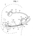
- the wearable display system of the present embodiment comprises: headphones 10 that can be mounted on the head H of a user; and a wearable display unit 20 that is fixed to the headphones 10.
- Fig. 1 is a perspective view showing the wearable display system of the first embodiment.
- Fig. 2 is a cutaway plan view showing main parts of the wearable display system (in a state of a projecting position).
- Fig. 3 is a cutaway plan view showing the main parts of the wearable display system (in a state of a retracted position).
- the headphones 10 of this wearable display system comprises: left and right speakers 11L and 11R; and an arm 12 that connects the left and right speakers 11L and 11R with each other. Both end portions of the arm 12 are curved such that these end portions can be placed on the left and right ears of the user. Thus, these end portions form earpieces 13L and 13R.
- the headphones 10 are rear-arm type headphones whose arm 12 is positioned around the back of the head of a user.
- the wearable display unit 20 comprises: an image display unit 21 that displays an image in front of a user's eye; a display support member 27 that fixes the image display unit 21 at its end portion; an display support member holding part 30 that supports the display support member 27 slidably; and an attachment 40 that fixes the display support member holding part to the headphone arm 12.
- the display support member 27 has a bar shape curved smoothly at a radius of curvature R.
- the center of curvature of the display support member 27 lies inside the head H.
- This display support member 27 is supported by the display support member holding part 30 such that the image display unit 21 can move between a retracted position d ( Fig. 3 ) and a projecting position c ( Figs. 1 and 2 ) along a locus B corresponding to the curved shape of the display support member 27.
- the display support member 27 is housed in the display support member holding part 30.
- the display support member 27 projects from the display support member holding part 30 and the image display unit 21 can display an image in front of a user's eye.
- the image display unit 21 is fixed at the end portion of the display support member 27 in such a way that the display unit 21 can swing in the direction of the arrow A between a displayable position a where a visual surface of the image display unit 21 faces a user's eye and non-displayable position b where the display screen is inclined at a angle larger than or equal to a certain angle with the line of sight of the user's eye.
- the length of the display support member 27 is determined such that the display screen of the image display unit 21 can be at a distance of 20 mm or more from the user's eye when the image display unit 21 is at the displayable position.
- the distance of 20 mm or more is determined considering the case where a user uses a pair of glasses.
- the image display unit 21 comprises: a display device 22; an optical system 23 for leading an image displayed by the display device 22 to a user's eye; a display unit position detection sensor 24 for detecting whether the image display unit 21 is in the above-mentioned displayable position or in the non-displayable position; and a display unit housing 25 that houses these components.
- the display unit housing 25 is formed with a fixing member 26 that is fixed to the end portion of the display support member 27.
- the display unit position detection sensor 24 is an optical sensor and detects whether the image display unit 21 is in the displayable position or the non-displayable position based on a change of a relative position of the display support member 27 within the display unit housing 25.
- the display support member holding part 30 comprises: a display support member housing 31 formed with an internal space that can house the display support member 27; guide rollers 34a and 34b that can support the display support member 27 slidably; a driving roller 35a that makes the display support member 27 slide; an display support member driving motor 35b that makes the driving roller 35a rotate; a retraction detection sensor 37a that detects whether the display support member 27 is in the above-mentioned retracted position d or not; a projection detection sensor 37b that detects whether the display support member 27 is in the above-mentioned projecting position c or not; and an display support member drive switch 36 for instructing operation of the display support member driving motor 35b.
- the internal space of the display support member housing 31 is curved correspondingly to the curved shape of the display support member 27.
- an display support member insertion hole 32 through which the display support member 27 enters and exits the display support member housing 31.
- a clearance part 33 is formed in the other end (hereinafter, referred to as a rear end) of the display support member housing 31, in the other end (hereinafter, referred to as a rear end) of the display support member housing 31, there is formed a clearance part 33.
- the clearance part 33 is a part that extends in a direction for keeping away from the headphone arm 12 so as to prevent interference between the speaker 11L or 11R of the headphones 10 and the display support member housing 31 when the attachment 40 is coupled to the headphone arm 12.
- a pair of guide rollers 34a, 34b is provided in each of two places along a moving path B of the display support member 27.
- the driving roller 35a is provided on the inner side of the curved display support member 27, i.e. on the side of the user's head.
- the shape of the outer periphery of the display support member 27 in a cross section perpendicular to its longitudinal direction has parts of different distances from the center of gravity of the cross section.
- that shape is not a circle.
- the shape is nearly circular, but formed with grooves 28a and 28b on the inner side and the outer side (i.e. the other side) of the curved display support member 27 respectively, to form anti-rotation-shape parts.
- the shape of the cross section of the display support member 27 is not circular in order to prevent rotation around its longitudinal axis.
- the grooves 28a and 28b on the internal and outer sides of the display support member 27 extend in the longitudinal direction of the display support member 27.
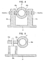
- Fig. 4 shows the cross section taken along the C-C line in Fig. 2
- Fig. 5 the cross section taken along the D-D line in Fig. 2 .
- the above-mentioned pair of guide rollers 34a, 34a (34b, 34b) is in contact with the insides of the grooves 28a and 28b (i.e. the anti-rotation-shape parts) of the display support member 27 and thus becomes abutting parts that abut on the anti-rotation-shape parts.
- Each guide roller 34a (34b) is rotatably mounted on a roller shaft 34c provided in the display support member housing 31.
- the above-mentioned driving roller 35a also is in contact with the bottom of the groove 28a on the inner side of the display support member 27, as shown in Fig. 5 .
- the driving roller 35a is mounted on a driving shaft of the display support member driving motor 35b fixed within the display support member housing 31.
- the driving roller 35a and the display support member driving motor 35b are arranged on the inner side of the display support member 27, the heavy component is positioned near to the head of a user as shown in Fig. 2 . This can improve stability at the time of movement of the head and reduce extension of the display support member housing 31 toward the outer side of the display support member, i.e. in the direction of getting away from the head.
- the attachment 40 is made of an elastic material such as resin and is formed to have a C-shaped cross section.
- a space d of the opening of the C-shape is slightly larger than the minor axis r2 of the headphone arm 12 whose cross section is an ellipse, although smaller than the major axis r1 of the headphone arm 12.
- the headphone arm 12 can be easily put into the attachment 40 by making the minor axis r2 of the headphone arm 12 vertical and thereafter by bringing the headphone arm 12 close to the opening of the attachment 40 in the X direction shown in the figure. Then, by relatively rotating the headphone arm 12 through 90 degrees, the headphone arm 12 is completely fitted in the attachment 40 as shown in Fig. 6B .
- the attachment 40 is elastically deformed to be slightly widened, and thus the attachment 40 grasps the headphone arm 12 tightly.
- the wearable display unit 20 has been fixed to the headphone arm 12.
- the wearable display unit 20 can be fixed to the headphone arm 12 by simply grasping the headphone arm 12.
- the attachment 40 grasps the headphone arm 12 by its elastic deformation, and can adapt to a headphone arm 12 having a slightly different cross section.
- the headphones 10 do not have a special fixing structure for the wearable display unit, and thus the beauty of the headphones is improved when it is used as a single item.
- the clearance part 33 of the display support member housing 31 is provided with a displacement mechanism 50.
- the displacement mechanism 50 is provided for changing the position and direction of the image display unit 21 relatively to the attachment 40.
- the displacement mechanism 50 comprises a ball 51 provided in the attachment 40 and a ball socket 52 formed in the clearance part 33 of the display support member housing 31. Frictional force larger than a certain magnitude acts between the ball 51 and the ball socket 52. Thus, the ball socket 52 can not rotate relatively to the ball 51 unless turning force larger than a certain magnitude acts on the ball socket 52 in relation to the ball 51.
- the displacement mechanism comprises the ball 51 and the ball socket 52 as described above, the display support member holding part 30, the display support member 27 held by the display support member holding part 30 and the image display unit 21 fixed to the display support member 27 can be displaced around each of three independent axes in the three-dimensional space.
- This displacement mechanism 50 may be provided between the display support member holding part 30 and the image display unit 21, or may be provided in the display support member holding part 30.
- the displacement mechanism 50 has its own weight. And, it is favorable to provide the displacement mechanism 50 between the attachment 40 and the display support member holding part 30 as in the present embodiment, in order to reduce the moment around the attachment 40 as far as possible.
- the ball 50 is formed on the side of the attachment 40. It needless to say, however, that the ball 50 can be formed on the side of the display support member housing 31 and the ball socket 52 on the side of the attachment 40.
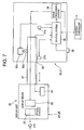
- Fig. 7 is a circuit block diagram showing the present wearable display system.
- the display support member housing 31 of the display support member holding part 30 is provided with the driving roller 35a, the display support member driving motor 35b, the retraction detection sensor 37a, the projection detection sensor 37b, the display support member drive switch 36, and in addition, a control system 38 and an image processing system 39.
- the control system 38 controls the display support member driving motor 35b based on signals from the various sensors 24, 37a and 37b and the display support member drive switch 36.
- the image processing system 39 sends an image signal to the display device 22 of the image display unit 21 based on a signal from an external controller C.
- the external controller C sends an audio signal to the headphones 10 through the wearable display unit 20. Or, reversely, it is possible that the external controller C sends the image signal, a control signal and the like in addition to the audio signal to the headphones 10 and the headphones 10 in turn sends the image signal, the control signal and the like among those signals to the wearable display unit 20.
- the external controller C sends an audio signal to the headphones 10 through the wearable display unit 20.
- the external controller C sends the image signal, a control signal and the like in addition to the audio signal to the headphones 10 and the headphones 10 in turn sends the image signal, the control signal and the like among those signals to the wearable display unit 20.
- the external controller C sends an audio signal to the headphones 10 through the wearable display unit 20.
- the external controller C sends the image signal, a control signal and the like in addition to the audio signal to the headphones 10 and the headphones 10 in turn sends the image signal, the control signal and the like among those signals to the wearable display unit 20.
- the attachment 40 of the wearable display unit 20 is coupled to the headphone arm 12 as described above. Then, the headphones 10 fixed with the wearable display unit 20 are mounted on the head. At that time, as shown in Fig. 3 , the image display unit 21 of the wearable display unit 20 is positioned in the non-displayable position b and the display support member 27 is in the retracted position d .
- the control system 38 detects an ON/OFF state of the display support member drive switch 36 and outputs a display support member drive control signal to the display support member driving motor 35b so that the display support member driving motor 35b starts driving the display support member 27 to project.
- the display support member 27 and the image display unit 21 move along the locus B corresponding to the curved shape of the display support member 27.
- the projection detection sensor 37b detects this and informs the control system 38 of this fact. Then, a projection off signal sent from the control system 38 stops the display support member driving motor 35b, and the display support member 27 stops at the projecting position c .
- the display unit position detection sensor 24 detects this change of position and informs the control system 38 of this fact.
- the control system 38 informs the external controller C of the fact that the image display unit 21 reaches the displayable position. Then, the external controller C knows that the wearable display unit 20 is ready to send the image signal.
- a play button of the external controller C is pushed in this state, the external controller C sends the image signal to the image processing system 39.
- the image processing system 39 in turn sends the image signal to the display device of the image display unit 21 to reproduce an image based on the image signal.
- the display support member drive switch 36 instead of pushing the display support member drive switch 36 at the beginning, it may be arranged as follows. Namely, when the play button of the external controller C is pushed, the external controller C sends the display support member drive control signal to the control system 38 to carry out the above-mentioned series of operations.
- the image display unit 21 is manually moved from the displayable position a to the non-displayable position b . Then, the display unit position detection sensor 24 detects this change of position, and informs the control system 38 of this change. The control system 38 informs the external controller C of the fact that the image display unit 21 reaches the non-displayable position b to stop sending of the image signal from the external controller C.
- the control system 38 detects an ON/OFF state of the display support member drive switch 36 and outputs the display support member drive control signal to the display support member driving motor 35b so that the display support member driving motor 35b starts driving the display support member 27 to retract.
- the display support member 27 moves along the locus B corresponding to its own curved shape.
- the retraction detection sensor 37a detects this and informs the control system 38 of this fact. Then, a retraction off signal sent from the control system 38 stops the display support member driving motor 35b, and the display support member 27 stops at the retracted position d.
- the display support member 27 and the image display unit 21 move along the locus corresponding to the curved shape of the display support member 27.
- the display support member 27 and the image display unit 21 move along the head of a user, and it is possible to suppress the distance between these components and the user's head to the minimum distance that does not cause interference with the user's head. This reduces the possibility that the image display unit 21 and the like touch other things even when the user's head moves during movement of the image display unit 21 and the display support member 27.
- the display support member 27 when the image display unit 21 does not display an image, the display support member 27 is at the retracted position where the display support member 27 is housed in the display support member housing 31. This reduces the moment of the wearable display unit 20 around the attachment 40 that is coupled to the headphone arm 12 as a head mounting belt. As a result, it is possible to reduce swinging of the wearable display unit 20 even if the user's head moves in a state that the image display unit 21 is retracted and the user's field of vision is ensured. This improves comfortableness of the mounted wearable display unit 20.
- the groove 28a is formed in the display support member 27 and the guide rollers 34a and 34b and the driving roller 35a are made to be in contact with the bottom of the groove 28a. This prevents rotation of the display support member 27 around its longitudinal axis whether the display support member 27 is moving or not.
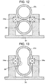
- Figs. 8 - 17 various variants of the anti-rotation-shape parts of the above-described wearable display unit 20 as well as various variants of the abutting parts that abut on the anti-rotation-shape parts.
- Figs. 8 - 10 , 12 and 13 are cross sections at the respective positions that correspond to the cross section at the C-C line in Fig. 2 .
- Fig. 11 is an explanatory view for illustrating difference in working methods according to a position of a groove to be formed in a curved bar-shaped member.
- the shape of cross section of the display support member 27a is almost rectangular and a groove is formed in one side of the display support member 27a.
- a guide roller 34a on the inner side of the display support member 27a is in contact with the inside of the groove 28a formed in one side of the display support member 27a, and a guide roller 34a on the outer side is in contact with the other side of the display support member 27a.
- the groove is formed only in the inner side of the display support member 27a, it is possible to control rotation of the display support member 27a as well as its movement in a direction other than the longitudinal direction, as long as the guide roller 34a enters the groove 28a on the inner side.
- the groove(s) of the display support member is (are) formed in the inner side or (and) the outer side, i.e. the left or (and) right side(s) of the display support member 27, 27a.
- basically same effects can be obtained when grooves of the display support member are formed instead in the top and/or the bottom of the display support member 27, 27a.
- a groove G1 can be formed without changing the direction of the rotation axis of the disk-shaped working tool W1 in the case where the groove G1 is to be formed on the inner side and/or the outer side of the curved bar-shaped member.
- a groove G2 is to be formed on a side perpendicular to the inner side-outer side direction of the curved bar-shaped member, the direction of the rotation axis of the disk-shaped working tool W2 should be changed successively as the working tool W2 moves.
- each display support member 27b, 27c has the shape of a rectangle or two-tiered vertical and horizontal rectangles in which no groove is formed.
- These variants also can prevent rotation of the display support member 27b, 27c around its longitudinal axis as in the above embodiment and the first variant.
- these second and third variants do not have a groove differently from the above embodiment and the first variant. Accordingly, to control movement of the display support member 27b, 27c in the up-and-down direction, i.e. the direction perpendicular to the inner side-outer side direction, it is necessary to provide a guide roller 34c at a position in the up-and-down direction.
- Each display support member 27c, 27d of these variants has a cross section of a circle-on-circle shape.
- a cross section of the display support member 27 of the fourth variant has a shape of two circles tangent to each other.
- a cross section of the display support member 27d of the fifth variant has a shape of two slightly-separated circles having connection parts between them.
- Each display support member 27c, 27d of these variants forms a groove 28 at a part of opposed arcs, and a guide roller 34a is in contact with this groove 28.
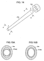
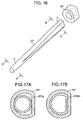
- each display support member 27e, 27a has different cross sections at the tip portion s at which the image display unit is fixed and at the base portion b on the other side. Further, each display support member 27e, 27f is supported by a slide shoe 34e, 34f. Each slide shoe 34e, 34f is fixed to the display support member insertion hole 32 shown in Fig. 1 .
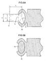
- the display support member 27e of the sixth variant has a cross section of a circular shape on the side of its tip portion s as shown in Fig. 15A and a cross section of an elliptical shape on the side of its base portion b as shown in Fig. 15B .
- Fig. 15A shows the cross sections of the display support member 27e and the slide shoe 34e both taken along the A-A line of Fig. 14 .
- Fig. 15B shows the cross sections of the display support member 27e and the slide shoe 34e both taken along the B-B line of Fig. 14 .
- the shape of the internal surface of the slide shoe 34e through which the display support member 27e is inserted is an elliptical shape of the same shape and size as the shape of the cross section of the display support member 27e on the side of its base portion b .
- the cross section of the display support member 27e on the side of its tip portion s has a shape of a circle as described above, and the diameter of the circle is same as the minor axis of the elliptical shape on the side of the base portion b .
- the display support member 27e can not rotate whether the display support member 27e is moving or not, and thus the image display unit is prevented from inclining.
- the image display unit is nearly positioned at the retracted position, it is possible to rotate the display support member 27e such that the image display unit is inclined suitably.
- the image display unit assumes the determined posture at the projecting position.
- lead wires from the display support member 27e have little play in the display support member housing 31, and there is a possibility that the lead wires may break when the display support member 27e rotates.
- the present embodiment prevents rotation of the display support member 27 when it is nearly at the projecting position, and accordingly the lead wires can be prevented from breaking
- the display support member 27f of the seventh variant has a cross section of a circular shape on the side of its tip portion s as shown in Fig. 17A and a cross section of an arc shape on the side of its base portion b as shown in Fig. 17B .
- Fig. 17A shows the cross sections of the display support member 27f and the slide shoe 34f both taken along the A-A line of Fig. 16 .
- Fig. 17B shows the cross sections of the display support member 27f and the slide shoe 34f both taken along the B-B line of Fig. 16 .
- the shape of the internal surface of the slide shoe 34f through which the display support member 27f is inserted is an arc shape of the same shape and size as the shape of the cross section of the display support member 27f on its side of the base portion b .
- the cross section of the display support member 27f on its side of the tip portion s has a shape of a circle as described above, and the diameter of the circle is same as the height of the arc (i.e. the height from the chord as the base) on the side of the base portion.
- the present variant can obtain the effects similar to the sixth variant.
- a motor fixing wall is formed as a high wall adapted for an external shape of the casing of the display support member driving motor 35b in order to prevent shift and swing of the display support member driving motor 35b.
- the motor fixing wall 35c is made lower so that the tip side of the display support member driving motor 35b can swing although it can not shift.
- the tip side of the display support member driving motor 35b is biased toward the display support member 27 by means of a spring 35d.
- the display support member driving motor 35b is fixed firmly as in the above-described embodiment, it is impossible to keep a prescribed contact pressure between the display arm support member 27 and the driving roller 35a mounted on the end of the display support member driving motor 35b unless the fixing position of the display support member driving motor 35b is determined very precisely. Even if the position of the display support member driving motor 35b is determined very precisely, the contact pressure changes when the display support member 27 moves and accordingly the relative distance between the driving roller 35a and the display support member 27 changes slightly. Thus, in the case where the contact pressure between the display support member 27 and the driving roller 35 can not be controlled to be constant, the driving roller 35a may slip on the display support member 27 so that the display support member 27 can not be moved by an intended distance.
- the contact pressure between the driving roller 35a and the display support member 27 is managed to be an intended contact pressure by holding the driving roller 35a toward the display support member 27 by means of the spring 35d while allowing the tip portion, i.e. the driving roller 35a of the display support member driving motor 35b to move in the direction of approaching to and leaving from the display support member 27.
- the display support member does not need to have a constant curvature as in the above-described embodiment, and for example, may be curved in a shape like a part of the circumference of an ellipse.
- the locus of the movement of the image display unit 21 completely coincides with the curved shape of the display support member 27.
- the locus of the image display unit is curved in a shape nearly similar to the curved shape of the display support member.
- the above-described embodiment has been described taking up the rear-arm type headphones 10.
- the present invention is not limited to this and may be applied to a head-arm type that is worn by putting its arm around the top of a head.
- the above-described embodiment is directed to headphones provided with speakers.
- the present invention can be applied to a head-mounted device as long as the device has an arm to be mounted on a head to hold the head from its left and right sides, even if the device is not provided with speakers.
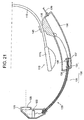
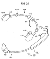
- FIG. 19 is a perspective view showing a wearable display system having an image display unit(in a coupled state) of the present embodiment, the image display unit of which can be arranged near a user's eye;
- Fig. 20 is a perspective view showing the wearable display system (in a non-coupled state);
- Fig. 21 is a cross section taken along the III-III line in Fig. 19 ;
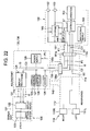
- Fig. 22 is a circuit block diagram of the wearable display system.
- the wearable display system of the present embodiment comprises headphones 110 and a wearable display unit 120 that can be mounted on the headphones 110 and the image display unit of which can be arranged near a user's eye.
- the headphones 110 comprises: left and right speakers 111L and 111R; a headphone arm 112 that connects the left and right speakers 111L and 111R with each other; earpieces 113L and 113R provided in the left and right speakers 111L and 111R respectively; and a cable connection part (an external connection part) 114.
- the headphones 110 are rear-arm type headphones whose headphone arm 112 is positioned around the back of the head of a user.
- the wearable display unit 120 comprises: an image display unit 121 that displays an image in front of a user's eye; an attachment 140 that is fixed to the headphone arm 112; a holding part 130 that couples an image display unit 121 to the attachment 140; and a cable 139 as a display-side electric connection part for electric connection with the headphones 110.
- the holding part 130 comprises: a bar-shaped display support member 131 whose cross section has an elliptic shape; and a display support member housing part 133 for housing the display support member 131.
- the longitudinal shape of the display support member 131 is curved correspondingly to a shape of a head of a user.
- the display support member housing part 133 has an internal space that can house most of the display support member 131.
- the external shape of this wearable display unit 120 including a display screen of the image display unit 121 is symmetrical about a horizontal plane in a state that the wearable display unit 120 is mounted horizontally on the head of a user.
- the display support member housing part 133 comprises: a display support member housing 136 for housing the display support member 131; a plurality of bearings 137 that slidably support the display support member 131; and a driving roller 138 for moving the display support member 131.
- a display support member insertion hole 134 for insertion of the display support member 131.
- the display cable (the display-side electric connection part) 139 for electric connection with the headphones 110.
- This clearance part 135 serves to avoid interference between the speaker 111L or 111R of the headphones 110 and the display support member housing 136.
- the driving roller 138 is connected to the below-mentioned display support member driving motor (shown in Fig. 22 ).
- the image display unit 121 comprises a display device 122 and an optical system 123 for the display device 122.
- the attachment 140 is made of an elastic material such as resin and is formed to have a C-shaped cross section similarly to the first embodiment.
- the wearable display unit 120 can be mechanically mounted to the headphone arm 112 by simply grasping the headphone arm 112. Thus, it is not necessary to prepare a dedicated attachment on the side of the headphones. In other words, the present embodiment does not need dedicated headphones.
- the cable connection part (the external connection part) 114 of the headphones 110 is connected with a controller 160 that controls the headphones 110 and the wearable display unit 120.
- This controller 160 comprises: a controller cable 161 connected with the cable connection part 114 of the headphones 110; an image signal receiving terminal 162 for receiving an image signal from the outside; an audio signal receiving terminal 163 for receiving an audio signal from the outside; an operation part 164 for user's operation; a signal storage part 165 for storing the image signal and the audio signal; an amplifier 166 that amplifies the audio signal; a control part 167 that sends a control signal to various parts according to instructions from the operation part 164; and a main power supply circuit 168.
- the controller cable 161 has a connector 161a provided with electric contacts.
- the connector 161a is provided with: an audio signal line S1 for sending the audio signal from the amplifier 166 to the cable connection part 114 of the headphones 110; an image signal line I1 for sending the image signal from the signal storage part 165 and the image signal receiving terminal 162 to the cable connection part 114 of the headphones 110; a control signal line C1 for sending the control signal from the control part 167 to the cable connection part 114 of the headphones 110; and a power line P1 for sending power from the main power supply circuit 168 to the cable connection part 114 of the headphones 110.
- the cable connection part 114 of the headphones 110 is provided with a controller-side connector 115a connected to the connector 161a of the controller cable 161 and a display-side connector (a headphone-side electric connection part) 115b connected to a connector 139a of the display cable 139.
- the controller-side connector 115a and the display-side connector 115b are connected with each other through an image signal line I2, a control signal line C2, a power line P2 and a ground line (not shown).
- the image signal line I1, the control signal line C1, the power line P1 and a ground line provided in the controller cable 161 are connected respectively to the image signal line I2, the control signal line C2, the power line P2 and the ground line that are connected to the controller-side connector 115a.
- the audio signal line S1 provided in the controller cable 161 is connected to the speakers 111R, and 111L through the connectors 161a and 115a and the audio signal line S2.
- a display processing part 124 for sending the image signal to the display device 122; a display support member drive control part 125 for moving the display support member 131; a gravity sensor 128 for detecting the up-and-down direction and for informing the display processing part 124 of a detection result; and a power supply circuit 129 for supplying electric power to these parts 124, 125 and 128 and to the display device 122.
- the display support member drive control part 125 comprises: a display support member driving motor 126 as a driving source for moving the display support member 131; a group of sensors 127 for detecting a forward movement critical position and a backward movement critical position of the display support member 131.
- the display cable 139 comprises: an image signal line I3 connected to the image signal line I2 of the display-side connector 115b of the headphones 110 through the connector 139a; a control signal line C3 connected to the control signal line C2 of the display-side connector 115b through the connector 139a; a power line P3 connected to the power line P2 of the display-side connector 115b through the connector 139a; and a ground line not shown.
- the image signal line I3 of the display cable 139 is connected to the display processing part 124 in the display support member housing 136; the control signal line C3 of the display cable 139 is connected to the display processing part 124 and the display support member drive control part 125 in the display support member housing 136; and the power line P3 of the display cable 139 is connected to the power supply circuit 129 in the display support member housing 136.
- the display support member 131 is provided with: an image signal line I4 for sending the image signal from the display processing part 124 in the display support member housing 136 to the display device 122; a power line P4 for supplying electric power from the power supply circuit 129 in the display support member housing to the display device 122; and a ground line not shown.
- the audio signal from the controller 160 not only the audio signal from the controller 160 but also the image signal, the control signal and the electric power are sent to the cable connection part 114 of the headphones 110.
- the audio signal is sent to each speaker 111R, 111L of the headphones 110, and the image signal, the control signal and the electric power are sent to the display support member housing part 133 of the wearable display unit 120 through the cable connection part 114 of the headphones 110.
- all the signals and the like sent from the controller 160 to the wearable display unit 120 and the headphones 110 are once sent to the headphones 110 so that the number of cables extending from the controller 160 becomes smaller.
- the attachment 140 of the wearable display unit 120 is mechanically coupled to the headphone arm 112 as described above.
- the attachment 140 of the wearable display unit 120 may be fixed either to the neighborhood of the right speaker 111R or to the neighborhood of the left speaker 111L of the headphone arm 112.
- the display cable 139 is connected to the display-side connector 115b of the headphones 110, to connect the headphones 110 and the wearable display unit 120 electrically.
- the controller cable 161 is connected to the controller-side connector 115a of the headphones 110, to connect the controller 160 and the headphones 110 electrically.
- the mechanical coupling and the electric connection of the wearable display unit 120 with the headphones 110 and the electric connection of the controller 160 with the headphones 110 can be carried out in any order.
- the headphones 110 with which the wearable display unit 120 is connected mechanically and electrically is mounted on the head.
- the user When a user wants to output sound together with a picture, the user operates the play button and the like of the operation part 164 of the controller 160.
- the main power supply circuit 168 outputs electric power and the control part 167 outputs the display support member drive control signal. Then, the electric power and the display support member drive signal are sent to the wearable display unit 120 through the cable connection part 114 of the headphones 110. The electric power is sent to the power supply circuit 129 of the wearable display unit 120, and then supplied various parts in the wearable display unit 120.
- the display support member drive signal is sent to the display support member drive control part 125 of the wearable display unit 120.
- the display support member driving motor 126 of the display support member drive control part 125 operates, and makes the display support member 131 project from the retracted position to the displayable position.
- the control part 167 of the controller 160 is notified of this fact. Then, according to an instruction from the control part 167, the image signal and the audio signal stored in the signal storage part or the image signal received through the image signal receiving terminal 162 and the audio signal received through the audio signal receiving terminal 163 are outputted to the cable connection part 114 of the headphones 110.
- the controller 160 sends the audio signal to each speaker 111R, 111L of the headphones to reproduce the sound corresponding to the audio signal. Further, the controller 160 sends the image signal to the display device 122 through the cable connection part 114 of the headphones 110 and the display processing part 124 of the wearable display unit 120, to reproduce the image corresponding to the image signal.
- the wearable display unit 120 is turned upside down.
- the external shape of the wearable display unit 120 (including the display screen of the image display unit 122) of the present embodiment is symmetrical in the vertical direction in a state that the wearable display unit 120 is mounted horizontally on the user's head.
- the gravity sensor 128 can detect the state, and the display processing part 124 automatically reverses the top and the bottom of a displayed image.
- the top of the displayed image is displayed correctly on the upper side.
- the display cable 139 of the wearable display unit 120 is removed from the cable connection part 114 of the headphones 110 and the attachment 140 of the wearable display unit 120 is removed from the headphone arm 112. In other words, the mechanical and electric connections between the headphones 110 and the wearable display unit 120 are released. Then, when the controller 160 sends the audio signal to the headphones 110, the sound corresponding to the audio signal is reproduced through the speakers 111R and 111L of the headphones.
- the mechanical and electric connections between the headphones 110 and the wearable display unit 120 can be released, and thus the headphones 110 can be used by themselves.
- the headphone arm 112 can be coupled mechanically to the wearable display unit 120 without providing a special fixing mechanism to the headphone arm 112 as a head mounting belt. As a result, the beauty of the headphones 110 is improved even at the time of using by themselves.
- the amplifier 166 is provided in the controller 160
- the amplifier 166 may be provided in the headphones 110.
- wires may be provided for supplying electric power from the controller 160 to the amplifier in the headphones 110.
- the display processing part 124 is provided in the display support member housing part 133 of the wearable display unit 120.
- a part of the functions of the display processing part 124 for example a function of driving the display device 122 may be provided in the image display unit 121.
- all the functions of the display processing part 124 may be provided in the image display unit 121.
- a part of various functional parts of the wearable display unit 120 and a part of various functional parts of the controller 160 may be suitably provided in other parts.
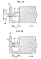
- Fig. 23 is a cross section showing the first variant of the attachment of the wearable display system of the second embodiment
- Fig. 24 is a cross section showing the second variant of the attachment of the wearable display system.
- the attachment 140a as the first variant comprises: a groove member 141 having a pair of side walls 142a and 142b opposed to each other; a second grasping member 143 that grasps the headphone arm 112 between it and one side wall (hereinafter, referred to as a first grasping member) 142a; and a screw member 144 as a pressing member that presses the second grasping member 143 toward the first grasping member 142a.
- the groove member 141 is formed unitedly with the clearance part 135 of the display support member housing part 133.
- the side wall 142a of the groove member 141 on the side of the clearance part 135 becomes the first grasping member.
- the other side wall 142b of the groove member 141 is formed with a threaded hole into which the screw member 144 as the pressing member is screwed.
- the second grasping member 143 is fixed to the tip of the screw member 144.
- a part of the headphone arm 112 is positioned between the first and second grasping members 142a and 143. Then, the screw member 144 is screwed to narrow the distance between the first grasping member 142a and the second grasping member 143 so that both grasping members 142a and 143 grasp the headphone arm 112 between them.
- the attachment 140b as the second variant is shown in Fig. 24 , and different from the first variant in that the screw member 144 as the pressing member is replaced by a spring coil 144b as an elastic member.
- a space between the first grasping member 142a and the second grasping member 143 is widened to shrink the spring coil 144b. Then, a part of the headphone arm 112 is placed between the first and second grasping members 142a and 143 so that the elastic force of the spring coil 144b pushes the second grasping member 143 toward the first grasping member 142b to grasp the headphone arm 112 between the grasping members 142b and 143.
- the wearable display unit can be coupled to the headphone arm 112 simply by grasping the headphone arm 112. Further, in these variants, the headphone arm 112 is grasped when the attachment 140a, 140b changes its form as a result of movement of the second grasping member 143. Accordingly, these variants can be adapted for a headphone arm 112 that has a slightly different cross section.
- the cable connection part 114 in the second embodiment is divided into three parts.
- cable connection parts 114a, 114R and 114L in the present variant are a controller cable connection part 114a to which the controller cable 161 from the controller 160 is connected, and two display cable connection parts 114R and 114L to which the display cable 139 from the wearable display unit 120 is connected.
- the controller cable connection part 114a is provided at the same position as the cable connection part 114 in the second embodiment, namely at the center of the headphone arm 112. And, two display cable connection parts 114R and 114L are each provided between the left or right speaker 111R or 111L and the controller cable connection part 114a. Each display cable connection part 114R, 114L has a connector to which the connector 139a of the display cable 139 can be connected. Similarly to the second embodiment described referring to Fig. 22 , each connector of the display cable connection parts 114R and 114L is connected with the power line P2, the image signal line 12, the control signal line C2 and the ground line from the connector of the controller cable connection part 114a.
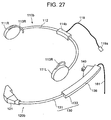
- Fig. 26 is a perspective view showing the wearable display system (in a coupled state) of the third embodiment
- Fig. 27 is a perspective view showing the wearable display system (in a non-coupled state)
- Fig. 28 is a circuit block diagram of the wearable display system.
- the wearable display system of the present embodiment has the basically same mechanical configuration as the configuration of the second embodiment except that arrangement of the power line, the signal line and the like is different.
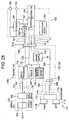
- the display support member housing 136 of the wearable display unit 120b is provided with connection parts at the end portion on the opposite side to the insertion hole for the headphone support member 131. These connection parts are connected with a headphone cable 119 extending from the headphones 110b and the controller cable 161 extending from the controller. As shown in Fig. 28 , within the display support member housing 136, are provided the display processing part 124, the display support member drive control part 125, the gravity sensor 128 and the power supply circuit 129 similarly to the second embodiment.
- the connection part to which the controller cable 161 is connected has a controller-side connector (an external connection part) 139c and the connection part to which the headphone cable 119 is connected has a headphone-side connector 139b.
- the controller-side connector 139c is connected with: an image signal line I2b connected to the image signal line I1 of the controller cable 161 through the connector 161a; a control signal line C2b connected to the control signal line C1 of the controller cable 161 through the connector 161a; a power line P2b connected to the power line P1 of the controller cable 161 through the connector 161a; and an audio signal line S2b connected to the audio signal line S1 of the controller cable 161 through the connector 161a. Further, ground lines not shown in the figure are connected to each other.
- the image signal line I2b extending from the controller-side connector 139c is connected with the display processing part 124.
- the control signal line C2b is connected with the display processing part 124, the display support member drive control part 125 and the gravity sensor 128. And, the power line P2b is connected with the power supply circuit 129. Further, the audio signal line S2b and the ground line are connected to the headphone-side connector 139b.
- the cable connection part 114b of the headphones 110b is provided with the headphone cable 119, and a connector (a headphone-side electric connection part) 119b of the headphone cable 119 is connected to the headphone-side connector (a display-side electric connection part) 139b of the wearable display unit 120b.
- the image signal, the audio signal and the electric power from the controller 160 are sent to the wearable display unit 120b.
- the audio signal is sent to the headphones 110b through the wearable display unit 120b.
- the other signal and the like are processed in the wearable display unit 120b.
- the headphones 110b of the present embodiment receives only the audio signal from the wearable display unit 120b and uses the headphone cable 119 for receiving the audio signal.
- the headphones 110b do not need a special fixing structure for mechanical coupling to the wearable display unit 120b.
- lead wires provided in the headphone cable 119 and the headphone arm 112 are only a right signal line, a left signal line and a ground line.
- thin wires can be used as the lead wires in the headphone cable 119 and the headphone arm 112.
- the headphones 110b itself can be made smaller and lighter and uncomfortable feeling at the time of mounting on the user's head can be reduced.
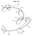
- Fig. 29 is a perspective view showing the wearable display system (in a non-coupled state) of the fourth embodiment
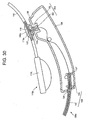
- Fig. 30 is a horizontal cross section showing main parts of the wearable display system of the fourth embodiment
- Fig. 31 is a vertical cross section showing an attachment of the wearable display system
- Fig. 32 is an explanatory view showing arrangement of electric contacts in left and right coupling portions of the wearable display system
- Fig. 33 is a circuit block diagram of the wearable display system.
- the wearable display system of the present embodiment also comprises headphones 110c and a wearable display unit 120c similarly to the above-described embodiments.
- a cable connection part 1114c to which the controller cable 161 is connected.
- respective coupling portions 116, 116 to which the wearable display unit 120c is coupled.
- a plurality of electric contacts 116a, 116a, ... are provided in each of these coupling portions 116, 116.
- each coupling portion 116 are formed on the outer side of the headphone arm 112 of an arc shape adapted for a shape of a head.
- an anti-rotation member 116b for preventing rotation of the wearable display unit 120c is formed on the inner side of each coupling portion. As shown in Fig. 31 , this anti-rotation member 116b projects toward the opposite side to the electric contacts 116a and has a width corresponding to the opening width of the attachment 140c having a C-shaped cross section.
- Fig. 31 shows cross sections of a coupling portion 116 and the attachment 140c coupled to the coupling portion 116.
- the clearance part 135 of the display support member housing 136 is provided with a displacement mechanism 150.
- the displacement mechanism 150 is used for changing the relative position and direction of the image display unit 121 with respect to the attachment 140.
- the displacement mechanism 150 comprises a ball 151 provided in the attachment 140 and a ball socket 152 formed in the clearance part 135 of the display support member housing 136. Frictional force larger than a certain magnitude acts between the ball 151 and the ball socket 152. Thus, the ball socket 152 can not rotate relatively to the ball 151 unless turning force larger than a certain magnitude acts on the ball socket 152 in relation to the ball 151. Further, as shown in the figure, lead wires are provided within the displacement mechanism 150.
- the internal surface of the attachment 140c of the C-shaped cross section is provided with a plurality of electric contacts 145c, 145c, .... that are respectively in contact with a plurality of electric contacts 116a, 116a, ... provided in each coupling portion 116 of the headphone arm 112.
- Theses electric contacts 145c are connected with the lead wires that form the signal lines and the power line. These lead wires pass through the insides of the attachment 140c and the ball 151 and extend toward the inside of the display support member housing 136.
- wiring of the signal lines and the like in the wearable display unit 120 and the headphones 110 is basically similar to the wiring of the second embodiment.
- the headphone arm 112 has a plurality of electric contacts 116a, 116a in each of the two portions (i.e. the left and right portions) in order to establish electric connection with the wearable display unit 120.
- the power line P2, the control signal line C2 and the image signal line I2 extending from the controller-side connector 115c of the headphones 110 are each branched on the way to extend to two electric contacts 116a, 116a.
- one set of electric contacts 116a become in contact with a plurality of electric contacts 145c provided in the attachment 140c at the time of mechanical coupling between the attachment 140c of the wearable display unit 120c and the headphone arm 112.
- the other set of electric contacts 116a are connected with terminating resistance for consuming a signal transmitted through the image signal line I2 so that the image signal is efficiently supplied to the display processing part 124.
- a cap having terminating resistance is put on the other set of electric contacts 116a.
- the top and the bottom of the wearable display unit 120c are reversed between the case where the wearable display unit 120c is coupled to the coupling portion 116 on the right side of the headphone arm 112 and the case where the wearable display unit 120c is coupled to the coupling portion 116 on the left side of the headphone arm 112. Accordingly, it is necessary to differentiate the arrangement of a plurality of electric contacts 116a in the coupling portion 116 on the right side from the arrangement of a plurality of electric contacts 116a in the coupling portion 116 on the left side.
- Fig. 32 is a view showing a state of the arrangements, seeing the left side coupling portion 116 and the right side coupling portion 116 from respective fronts of the surfaces in which electric contacts are arranged. As shown in the figure, it is assumed that, as a plurality of electric contacts 116a in each coupling portion 116, there exist contacts 1 - 8, and that, in the left coupling portion 116, the contacts 1 - 4 are placed from left to right in a row, and under this group of contacts, the contacts 5 - 8 are placed from left to right.
- the top and the bottom of the wearable display unit 120 are reversed and, as a result, also a plurality of electric contacts 145c provided in the attachment 140 are turned upside down. Accordingly, in the right coupling portion 116, the contacts 5 - 8 (which are placed on the lower side in the left coupling portion 116) are placed on the upper side and the contacts 1 - 4 (which are placed on the upper side in the left coupling portion 116) are placed on the lower side. Further, in the right coupling portion 116, the contacts 1 - 4 are placed from right to left, i.e. to the direction to which the headphone arm 112 extends, and the contacts 5 - 8 are placed from right to left also.
- the headphones 110c can be used by themselves. Further, since the electric contacts 116a, 145c are provided in the headphones 110c and the mechanical attachment 140c for electrically connecting the headphones 110c and the wearable display unit 120c, cables for electrically connecting the headphones 110c and the wearable display unit 120c are not required. Thus, the external appearance is improved.
- the gravity sensor 128 can detect vertical inversion of the image display unit 121 caused by a change of the position of coupling the wearable display unit 120.
- a sensor that detects a state of an electrical connection of at least one contact among a plurality of electric contacts in the attachment 120c of the wearable display unit 120 or at least one contact among a plurality of electric contacts in the left and right coupling portions 116.
- Output of this sensor is sent to the display processing part 124, similarly to the output of the gravity sensor 128 in the second embodiment. Based on the output of this sensor, the display processing part 124 can recognize whether the wearable display unit 120c is coupled on the right side or the left side and reverse the top and the bottom of the image.
- the attachment 140a or 140b of the first or second variant in the second embodiment may be used while providing electric contacts to the attachment 140a or 140b. This can produce similar effects, of course.
- a displacement mechanism 150a of this variant uses a flexible wire 153 instead of the ball 151 in the displacement mechanism 150 of the fourth embodiment.
- This flexible wire 153 is obtained by weaving fine wires into a wire rod of a certain thickness and filling resin into gaps between the fine wires and around the rod of the certain thickness.
- the flexible wire 153 is deformed under a force of a certain intensity and keeps the deformed state unless a force of a certain intensity is applied again.
- this flexible wire 153 is fixed to the clearance part 135 of the display support member housing 136, and the other end to the attachment 140c.
- this flexible wire 153 instead of the ball 151 in the fourth embodiment and deforming the flexible wire 153 in various directions, the holding part 130 and the image display unit 121 held by the holding part 130 can be displaced around each of three independent axes in the three-dimensional space, similarly to the fourth embodiment.
- the displacement mechanism 150 of the fourth embodiment or the displacement mechanism 150a of the present variant can be used in each of the above- and below-described embodiments.
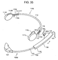
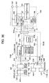
- Fig. 35 is a perspective view showing the wearable display system of the fifth embodiment
- Fig. 36 is a circuit block diagram of the wearable display system.
- the wearable display system of the present embodiment comprises headphones 110d and a wearable display unit 120d similarly to the above-described embodiments.
- each coupling portion 116, 116 is formed in the neighborhoods of the left and right speakers 111R and 111L of the headphone arm 112 of the headphones 110d.
- These coupling portions 116, 116 are each provided with a plurality of electric contacts 116d.
- projections 117, 117 are formed on both sides of each coupling portion 116.
- the electric contacts 116d of each coupling portion 116 are formed on the outer side of the headphone arm 112 of an arch shape adapted for a shape of a head.
- an anti-rotation member 116b for preventing rotation of the wearable display unit 120d.
- an attachment 140d of the wearable display unit 120 is coupled to a coupling portion 116 of the headphones 110d.
- the attachment 140d is basically similar to the attachment of the fourth embodiment, and the internal surface of the attachment 140d is provided with a plurality of electric contacts that are in contact with a plurality of electric contacts 116d, 116d provided in each coupling portion 116 of the headphone arm 112. These electric contacts are connected with lead wires that form the signal lines and the power line. These lead wires pass through the inside of the attachment 140d and extend toward the inside of the display support member housing 136.
- the width i.e.
- W2 of this attachment 140d is shorter than the width W1 of each coupling portion 116 of the headphone arm 112.
- the attachment 140d can move relatively to each coupling portion 116 of the headphone arm 112 by the length (W1 - W2) in the direction of the extension of the headphone arm 112. Accordingly, to ensure electric connections between the electric contacts 116d of each coupling portion 116 and the electric contacts in the attachment 140d, each electric contact 116d in the coupling portions 116 has the length larger than (W1 - W2) in the direction of the extension of the headphone arm.
- wiring of the signal lines and the like in the wearable display unit 120c and the headphones 110c is basically similar to the wiring of the third embodiment.
- the headphone arm 112 has a plurality of electric contacts 116d, 116d in each of the two portions (i.e. the left and right portions) in order to establish electric connection with the wearable display unit 120d.
- the audio signal line S3b extending from each speaker 111R, 111L of the headphones 110d are branched on the way to extend to two electric contacts 116d, 116d.
- one set of electric contacts 116d become in contact with a plurality of electric contacts 145d provided in the attachment 140d at the time of mechanical coupling between the attachment 140d of the wearable display unit 120d and the headphone arm 112.
- the present embodiment can obtain basically same effects as ones obtained by the fourth embodiment. Further, in the present embodiment, the wearable display unit 120d can be moved relatively to the headphones 110 in the direction in which the headphone arm 112 extends. As a result, it is possible to have a larger degree of freedom of displacement of the wearable display unit 120d in relation to the headphones 110d, in comparison with the fourth embodiment.
- Fig. 37 is a perspective view showing the wearable display system of the sixth embodiment
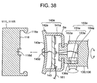
- Fig. 38 is a cross section showing a speaker, an attachment and a displacement mechanism of the wearable display system
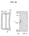
- Fig. 39 is a cross section showing a speaker and an outer cap of the wearable display system.
- the wearable display system of the present embodiment comprises headphones 110e and a wearable display unit 120e, similarly to the above-described embodiments.
- the wearable display system of the present embodiment has the basically same circuit configuration, wiring of the signal lines and the like as those of the wearable display system of the fifth embodiment described referring to Fig. 36 .
- the present embodiment is different from the above-described embodiments in that the wearable display unit 120e is coupled to a speaker 111 of the headphones 110e.
- positions of electric contacts for electrically connecting the headphones 110 and the wearable display unit 120e are different from ones in the fourth embodiment.
- a coupling portion 118 to which the wearable display unit 120e is to be coupled, is formed in each of left and right speakers 111R and 111L of the headphones 110e on the side opposite to the side contacting with a user's head.
- this coupling portion 118 is formed with a collar 118a projecting toward the inner side at an opening edge of a groove.
- This collar 118a is formed with elastic resin and can be deformed.
- a plurality of electric contacts 116d, 116d, ... for receiving the audio signal.
- the wearable display unit 120e comprises: an image display unit 121 for displaying an image in front of a user's eye; an attachment 140e that can be coupled to the coupling portion 118 of each speaker 111R, 111L; and a holding part 130 that connects the image display unit 121 to the attachment 140e.
- the attachment 140e has a shape that can be inserted into the coupling portion 118 of a speaker 111.
- the attachment 140e comprises: an attachment main body 141e of a hollow cylinder shape; and a coupling collar 142e that enters between the bottom of a coupling portion 118 and the collar 118a of the coupling portion 118.
- the coupling collar 142e is provided on the outer periphery of the bottom 143e of the attachment main body 141e.
- the collar 118a of the coupling portion 118 of the speaker 111 is deformed elastically, to insert the coupling collar 142e of the attachment 140e between the bottom of the coupling portion 118 and its collar 118a.
- the bottom 143e of the attachment main body 140e is provided with electric contacts 145d that are to be connected to the electric contacts 116d of a speaker 111.
- these electric contacts 145d are electrically connected to the electric contacts 116d of the coupling portion 118.
- the wearable display system of the present embodiment has the basically same circuit configuration, wiring of the signal lines and the like as those of the fifth embodiment.
- the present embodiment is different from the fifth embodiment in that a part of the circuit configuration provided in the display support member housing 136 is placed inside the hollow attachment main body 141e. Further, a circuit board formed with such circuits is connected with the controller cable 161 extending from the controller 160. The above-mentioned electric contacts 145d of the attachment 140e are connected, through the circuit board 143, with the audio signal line included in the controller cable 161. Further, the control signal lines, the image signal line, the power line and the like extend from each circuit 124, 129 or the like on the circuit board 143.
- the control signal lines are connected to the display support member drive control part 125 and the like provided in the display support member housing 136 of the holding part 130.
- the image signal line is connected to the image display unit 121.
- the power line supplies electric power to the display support member drive control part 125 and the image display unit 121..
- a displacement mechanism 150e for changing the directions and positions of the holding part 130 and the image display unit 121 relatively to the attachment 140e is provided between the display support member housing 136 and the attachment 140e.
- the displacement mechanism 150e comprises: an up-and-down movement rotation axis member 151e for moving the image display unit 121 up and down; and a left-and-right movement rotation axis member 154e for moving the image display unit 121 to the left and to the right.
- the up-and-down movement rotation axis member 151e comprises: an axis member 152e that is fixed to the attachment 140e on the opposite side to the electric contacts 145d; and a bracket member 153e that extends from the axis member 152e toward the holding part 130.
- the left-and-right movement rotation axis member 154e passes through the bracket member 153e of the up-and-down movement rotation axis member 151e and a bracket member 136e of the display support member housing 136.
- frictional force larger than a certain magnitude acts between the axial parts and the socket parts, and thus a socket part does not rotate relatively to an axial part unless a force larger than a certain level is applied from the side of the display support member housing 136.
- each of the right speaker 111R and the left speaker 111L is formed with a coupling portion 118.
- the wearable display unit 120e is coupled to the right speaker 111R for example, the coupling portion 118 of the left speaker 111L is exposed.
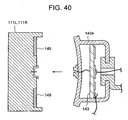
- the present embodiment has an outer cap 140f for covering the coupling portion 118 of a speaker 111 to which the wearable display unit 120e is not coupled.
- the outer cap 140f is similar to the attachment 140e in their external appearances, and has a collar 142f that is fit into the coupling portion 118 of each speaker 111.
- the outer cap 140f is hollow similarly to the attachment 140e, and a division plate 143f similar to the circuit board 143 of the attachment 140e is provided inside the outer cap 140f.
- the division plate 143f is provided in order to form the same space Sf within the outer cap 140f as a space Se formed between the circuit board 143 and the bottom 143e of the attachment main body 141e as a result of providing the circuit board 143 in the attachment 140e. Owing to this arrangement, it is possible to obtain the same sound quality both from the left speaker 111L and the right speaker 111R.
- all the signals and the like sent from the controller 160 to the wearable display unit 120e and the headphones 110e are once sent to the wearable display unit 120e similarly to the third and fifth embodiments.
- the number of cables extending from the controller 160 can be reduced.
- the outer cap 140f can consume the image signal, it is not necessary to provide a terminating resistance separately.
- all the signals and the like sent from the controller 160 to the wearable display unit 120e and the headphones 110 are once sent to the wearable display unit 120e.
- all the signals and the like sent from the controller 160 to the wearable display unit 120 and the headphones 110e are once sent to the headphones 110e, and the wearable display unit 120e receives the image signal and electric power from the headphones 110.
- the attachment 140e is coupled to a speaker 111 by deformation of an elastic body.
- a magnet 149 may be provided to either of the attachment 140e and a speaker 111, and a magnetic body such as iron may be provided to the other so that the attachment 140e is attached to the speaker 111.
- Fig. 41 is a perspective view showing an external appearance of the wearable display system in the case where the wearable display system is mounted on a head H of a user U.
- the head H includes the neck of the user U who uses the wearable display system, and thus refers to the neck and a part above the neck.
- the wearable display system of the present embodiment comprises: headphones 210 that is to be mounted on a head H and has functions of generating sound such as voice, music, sound effects and the like; and a wearable display unit 220 that has a function of displaying an image for a user U. Further, the wearable display unit 220 is connected with a cable 230.
- the cable 230 supplies electric power and sound/image signals from a power supply unit (not shown) and a sound/image signal generation unit (not shown) to the wearable display system.
- the headphones 210 comprises: a right speaker 211a; a left speaker 211b; a right earpiece 212a; a left earpiece 212b; and a headphone arm 213 that connects the right and left speakers 211a and 211b.
- the right speaker 211a and the left speaker 211b have a sound output function, and a sound signal from the cable 230 is supplied to these speakers 211a and 211b.
- the right earpiece 212a is connected to the right speaker 211a and assists the right speaker 211a to be mounted on and in close contact with the head H.
- the left earpiece 212b is connected to the left speaker 211b and assists the left speaker 211b to be mounted on and in close contact with the head H.
- the headphone arm 213 holds the head H of the user U inside the headphone arm 213 by its elastic force and connects the right speaker 211a and the left speaker 211b with each other.
- the wearable display unit 220 comprises: a image display unit 222; a holding part 221 that can hold the image display unit 222 in front of an eye of the user U; an attachment 227 that connects the holding part 221 and the headphone arm 213; an auxiliary holding part 240 provided to the holding part 221; a head pressing detection sensor 250 provided in the auxiliary holding part 240.
- the auxiliary holding part 240 is provided to the holding part 221 at a position where the auxiliary holding part 240 does not enter the field of vision of the user U in a state that the center of the field of vision of the user U coincides with the center of an image on the image display unit 222.
- the image display unit 222 reproduces and displays the image signal sent through the cable 230.
- the known techniques can be used for reproduction and display of the image signal.
- the holding part 221 comprises : a connection part 223; a display support member 224; and a display support member housing part 225.
- connection part 223 connects the image display unit 222 and the display support member 224.
- the connection part 223 may use a ball joint so that the direction of displaying an image on the image display unit 222 can be changed continuously centering on the connection part 223.
- Fig. 42 is a cross section showing main parts of the wearable display system.
- the display support member 224 is a pipe-shaped arm and draws a curve running along a curve extending from the temporal part of the head H to the face part.
- the display support member 224 has strength that bears the weight of the image display unit 222 and the connection part 223.
- the display support member housing part 225 houses at least a part of the display support member 224 as well as at least a part of the auxiliary holding part 240 in its inside.
- the display support member 224 when the image display unit 222 is retracted from the front of an eye of the user U and at least a part of the display support member is housed in the display support member housing part 225 as shown in Fig. 42 , it is said that the display support member 224 is in a housed position. Further, when the display support member 224 supports the image display unit 222 in front of a user's eye ( Fig. 41 ), it is said that the display support member 224 is in a projecting position.
- the display support member housing part 225 comprises: a display support member housing 226; a display support member position detection sensor 231; a holding part driving unit 232; a control unit 235; and a mode selection switch 236.
- a housing space 226a inside the display support member housing 226 has sufficient size for housing the display support member 224 and the auxiliary holding part 240 positioned along the display support member 224. Further, the housing space 226a has depth for housing at least a part of the display support member 224.
- the display support member position detection sensor 231 is a pressure sensor. Instead of this sensor 231, the sensors of the first embodiment may be used. A fixing location of the display support member position detection sensor 231 is the innermost portion of the housing space 226a. In the present embodiment, when the display support member 224 is positioned at the housed position, one end 224d of the display support member 224 at which the image display unit 222 is not fixed presses the innermost portion of the housing space 226. As a result, the display support member position detection sensor 231 detects the pressure from the display support member 224, and thus detects that the display support member 224 is at the housed position.
- the holding part driving unit 232 comprises: a display support member driving motor (not shown); a power line (not shown) and a control line (not shown) connected to the display support member driving motor; a motor shaft 233; and a driving roller 234 fixed to the motor shaft 233.
- An outer periphery of the driving roller 234 is in contact with an inner side surface of the curved display support member 224.
- the driving roller 234 can move the display support member 224 slidingly by the turning force given from the electric motor to the motor shaft 233.
- the mode selection switch 236 is partly projecting outside the display support member housing 226, and thus it is possible to operate the mode selection switch 236 while using the display support member housing 226.
- the mode selection switch 236 switches between three modes, i.e. a manual mode in which sliding operation of the display support member 224 is carried out manually, an electric operation mode in which the holding part driving unit 232 is activated electrically, and an off mode in which the switch is turned off. In the cases of the electric operation mode and the manual mode, a stopper for stopping rotation of the driving roller 234 is released.
- Fig. 43 is a cross section showing a part of the display support member 224, the auxiliary holding part 240 and the head pressing detection sensor 250.
- the auxiliary holding part 240 comprises: a pressing member 401 that presses the head H at a pressure larger than a certain value; a shaft member 402; a spring fixing member 403; and a mounting member 405 for mounting the shaft member 402 to the display support member 224.
- the pressing member 401 is provided with the head pressing detection sensor 250. Further, a movement sensor 407 for detecting a change in movement of the head H is provided within the pressing member 401.
- the pressing member 401 has a spherical shape and is connected to the shaft member 402. Further, the pressing member 401 presses the head H.
- the shaft member 402 is swingably mounted to the display support member 224 by means of the holding member 224a and the pin 224b through the mounting member 405.
- a pressing force generation unit 245 generates a pressing force of the auxiliary holding part 240, and comprises electromagnets 451 and 452 and a spring 453.
- the electromagnet 452 is fixed to the shaft member 402, and the electromagnet 451 is fixed to the display support member 224 to face the electromagnet 452.
- the electromagnets 451 and 452 are supplied with electric power from the display support member housing part 225 through power lines not shown. Further, directions and strengths of electric currents to the electromagnets 451 and 452 can be controlled by the control unit 235 ( Fig. 44 : described below) in the display support member housing part 225. Thus, it is possible to control electromagnetic forces such that the electromagnets 451 and 452 attract or repel each other.
- One end of the spring 453 is fixed to the spring fixing member 224c on the display support member 224.
- the other end of the spring 453 is fixed to the spring fixing member 403 on the shaft member 402.
- the movement sensor 407 provided within the pressing member 401 comprises a gyro sensor.
- the movement sensor 407 detects a change in movement of the head H in a state that the pressing member 401 presses against the head H.
- the head pressing detection sensor 250 is mounted on the surface of the pressing member 401 at a portion that presses against the head H.
- Output of the movement sensor 407 and output of the head pressing detection sensor 250 are sent to the control unit 235 provided in the display support member housing part 225 through respective signal lines ( Fig. 44 ).
- a pressing position of the auxiliary holding part 240 when the pressing member 401 of the auxiliary holding part 240 is at a position where the pressing member 401 can press against the head H, that position is referred to as a pressing position of the auxiliary holding part 240. Further, when the pressing member 401 of the auxiliary holding part 240 is at a position where the pressing member 401 can not press against the head H, that position is referred to as a retracted position of the auxiliary holding part 240.
- the auxiliary holding part 240 is provided in such a manner that the auxiliary holding part 240 can swing between the pressing position and the retracted position.
- Fig. 44 is a circuit block diagram relating to driving/control of the wearable display system.
- the control unit 235 is connected with the display support member position detection sensor 231, the holding part driving unit 232 and the mode selection switch 236 provided in the display support member housing part 225, the movement sensor 407 and the pressing force generation unit 245 placed in the auxiliary holding part 240, the head pressing detection sensor 250, and the image display unit 222, through respective signal lines.
- the control unit 235 sends and receives signals through those signal lines. Further, based on the output S1 of the head pressing detection sensor 250, the control unit 235 controls the pressing force generation unit 245 such that the pressing level stays within a predetermined range. Further, based on the output S3 of the display support member position detection sensor 231, the control unit 235 controls the display support member driving motor of the holding part driving unit 232 such that the display support member 224 is positioned at the projecting position or the housed position.
- Control and operation from the start of using the wearable display system and to the end of using will be described in order. In the following description, control signals between blocks will not be mentioned and only data from each sensor will be mentioned.
- control unit 235 controls the holding part driving unit 232 to drive the display support member 224 from the housed position to the projecting position. As a result, the image display unit 222 is held in front of an eye.
- the control unit 235 releases the stopper for the display support member 224.
- the stopper is provided in the holding part driving unit 232.
- the user manually pulls the display support member 224 from the housed position to the projecting position.
- operation/control of the wearable display system becomes as follows.
- control unit 235 uses a movement detection signal S2 of the movement sensor 407 to control the pressing force generation unit 245. For example, based on the movement detection signal S2 from the movement sensor 407, the control unit 235 calculates a change in movement of the head H. Then, according to the calculated change, the control unit 235 may control the pressing force generation unit 245 such that the pressing level of the pressing member 402 remains within the predetermined range. Further, switching between the retracted position and the pressing position of the auxiliary holding part 240 may be carried out manually. In that case, the manual operation is carried out in a state that the mode selection switch 236 is at the manual mode.
- one of the electromagnets 451 and 452 may be a magnetic body such as iron.
- the electromagnetic force may be turned off and only the elastic force of the spring 453 may be used.
- it is sufficient to control the electromagnetic forces of the electromagnet such that the electromagnetic force larger than the elastic force attracts the magnetic body.
- a lock mechanism may be provided for keeping the retracted position.
- the auxiliary holding part 240 is provided to the display support member 224 on the side of the display support member housing part 225 at the position where the auxiliary holding part 240 exists outside the field of vision of the user U when the user U views the image on the image display unit 222.
- the auxiliary holding part 240 rarely interrupts the field of vision of the user U to an uncomfortable degree.
- the wearable display system of the present embodiment does not spoil visibility of surroundings.
- the auxiliary holding part 240, the pressing force generation unit 245 and structure of members required for operations and the like of these components of the present embodiment may be employed in the first through sixth and eighth through eleventh embodiments.
- an auxiliary holding part 240 similar to the one of the seventh embodiment is provided not on the display support member 224 but on the display support member housing part 225. Accordingly, the holding member 224a, the pint 224b and the spring fixing member 224c are provided not on the display support member 224 but on the display support member housing part 225. Further, the electromagnet 451 of the pressing force generation unit 245 is placed on the display support member housing part 225. Also, one end of the spring 453 is fixed to the display support member housing part 225.
- the other structures are common to the seventh embodiment. Thus, the same reference numbers are given to the common components. Further, repeated description with respect to the common components and their operation and control will be omitted.
- Fig. 45 shows a state that the display support member 224 is in the projecting position and the auxiliary holding part 240 provided swingably on the display support member housing part 225 is in the pressing position where the auxiliary holding part 240 presses against the temporal part.
- the display support member 224 is driven to the projecting position manually or by the holding part driving unit 232 (the arrow A).
- the pressing force generation unit 245 operates according to control similar to the control in the seventh embodiment.
- the auxiliary holding part 240 is positioned at the pressing position where the pressing member 401 presses against the temporal part of the head H (the arrow B).
- Fig. 46 is a perspective view showing the external appearance of the wearable display system of the present embodiment in a state that the display support member 224 is at the housed position.
- the auxiliary holding part 240 provided on the display support member housing part 225 is at the retracted position.
- the display support member 224 is housed to the housed position manually or by the holding part driving unit 232 (the arrow C).
- the pressing force generation unit 245 operates according to control similar to the control in the seventh embodiment.
- the auxiliary holding part 240 is positioned at the retracted position (the arrow D).
- the auxiliary holding part 240 presses against the temporal part of the head H.
- it may be arrange such that the auxiliary holding part 240 presses against the left speaker 211b.
- a change in movement of the head H may be detected by the movement sensor 407.
- pressing by the auxiliary holding part 240 may be controlled depending on the change in movement of the head H.
- switching between the retracted position and the pressing position of the auxiliary holding part 240 may be carried out manually. In that case, this operation may be carried out under the manual mode selected by the mode selection switch 236.
- the auxiliary holding part 240 provided on the display support member housing part 225 presses against the temporal part of the head.
- the auxiliary holding part 240 is positioned outside the field of vision of the user U, and the auxiliary holding part 240 scarcely enters the field of vision of the user U viewing the image.
- the wearable display unit 220 of the present embodiment can suppress movement of the image display unit 222 and improves visibility of surroundings.
- a wearable display system the image display unit of which can be arranged near a user's eye, of a ninth embodiment will be described referring to Fig. 47 and 48 .
- an auxiliary holding part 241 having a new mechanism is provided on the display support member housing part 225. Further, the auxiliary holding part 241 is in a pressing position where the auxiliary holding part 241 can press, before mounting the wearable display system on the head.
- the other features of the present embodiment are common to the second embodiment. Accordingly, the same reference numbers are given to the common components. Further, repeated description with respect to the common components and their operation will be omitted.
- Fig. 47 shows a state that the display support member 224 is at the projecting position and the auxiliary holding part 241 provided on the display support member housing part 225 is at the pressing position.
- Fig. 48 is a cross section showing the auxiliary holding part 241 at the pressing position and a part of the display support member housing part 225.
- the auxiliary holding part 241 comprises: a disk-shaped pressing member 411; and a cylinder 412 that is connected to the pressing member 411 at one end and has a cylinder-shaped hollow portion 413. Further, an open end of the cylinder 412 is slidably inserted into a hole that is provided in the display support member housing part 225 and has a diameter nearly same as the diameter of the cylinder 412. Further, the auxiliary holding part 241 has a pressing force generation unit 245a.
- the pressing force generation unit 245a has a spring 453.
- the spring 453 has a diameter nearly same as the diameter of the hollow portion 413.
- One end of the spring 453 is fixed to the spring fixing portion 414 of the auxiliary holding part 241.
- the other end of the spring 453 is fixed to a spring fixing portion 258 provided in the bottom of the hole of the display support member housing part 225.
- Elastic force of the spring 453 applied to the spring fixing portion 414 of the auxiliary holding part 241 is adjusted such that the auxiliary holding part 241 can keep the pressing position irrespective of a posture of the wearable display system.
- Operation/control of the wearable display system are almost similar to those of the eighth embodiment except that the auxiliary holding part 241 is at the pressing position already before mounting the wearable display system on the head. Namely, the user U mounts the wearable display system on his head H while his head H is pressing back the auxiliary holding part 241 positioned at the pressing position. Mounting operation after that is similar to the operation in the eighth embodiment except that the auxiliary holding part 241 is always at the pressing position where the auxiliary holding part 241 can press.
- an electromagnet is provided on the bottom of the hole ( Fig. 48 ) in the display support member housing part 225 and a magnetic body such as iron is provided at a part of the pressing member 411.
- the electromagnetic force attracts the pressing member 411 to the electromagnet in the bottom of the hole against the elastic force of the spring 453.
- at least a part of the auxiliary holding part 241 may be housed in the hole in the display support member housing part 225. Further, to place the auxiliary holding part 241 at the pressing position, it is sufficient to turn off the electromagnetic force of the electromagnet so that only the elastic force of the spring 453 makes the auxiliary holding part 241 project.
- the auxiliary holding part 241 provided on the display support member housing part 225 presses against the temporal part of the head.
- the auxiliary holding part 241 is positioned outside the field of vision of the user U, and the auxiliary holding part 241 scarcely enters the field of vision of the user U viewing the image.
- Fig. 49 shows a first variant of the ninth embodiment.
- an attachment 227 connects the display support member housing part 225 not to the headphone arm 213 but to the left speaker 211b.
- the other components and their operations are similar to the ones in the ninth embodiment.
- Fixing structure of this attachment 227 to the speaker 211b may be the above-described structure shown in Fig. 39 .
- the display support member housing part 225 is connected to the left speaker 211b, and thus the auxiliary holding part 241 scarcely enters the field of vision of the user U viewing the image.
- the wearable display unit of the present variant it is possible to suppress movement of the image display unit 222 and to improve visibility of surroundings.
- Fig. 50 shows a second variant of the ninth embodiment.
- the auxiliary holding part 241 presses against not the head H but the left speaker 211b.
- the other components and their operations are similar to the one in the ninth embodiment.
- the auxiliary holding part 241 presses against the head H through the left speaker 211b.
- the auxiliary holding part 241 scarcely enters the field of vision of the user U viewing the image.
- FIG. 51 is a perspective view showing the wearable display system of the present embodiment
- Fig. 52 is a cutaway plan view showing main parts of the wearable display system
- Fig. 53 is a cross section taken along the A-A line in Fig. 52 .
- the wearable display system of the present embodiment comprises: headphones 210a and a wearable display unit 220a similarly to the above-described embodiments.
- the headphones 210a comprises: a right speaker 211a; a left speaker 211b; and a headphone arm 213a that connects the right speaker 211a and the left speaker 211b with each other.
- the headphone arm 213a is curved in the respective neighborhoods of the speakers 211a and 211b, and these curved portions form earpieces 214.
- the wearable display unit 220a comprises: an image display unit 222; a holding part 221; an attachment 227; and an auxiliary holding part 240a.
- the wearable display unit 220a of the present embodiment further comprises: a projection length adjustment part 260 for adjusting the projection length of the auxiliary holding part 240a; a distance adjustment part 265 for adjusting the distance from the attachment 227 to the holding part 221; a joint 270 for fixing the holding part 221 swingably to the attachment 227; and a spring coil 275 as a pressing force generation means that generates a pressing force F at the auxiliary holding part 240a.
- a fixing part for fixing the auxiliary holding part 240a On the side of the image display unit 222 of the display support member housing part 225 of the holding part 221, is provided a fixing part for fixing the auxiliary holding part 240a.
- a shaft portion of the auxiliary holding part 240a of the present embodiment is formed with a male screw 261.
- the fixing part of the display support member housing part 225 is formed with a female screw 262 into which the male screw 261 of the auxiliary holding part 240a is screwed and coupled.
- the projection length adjustment part 260 comprises the male screw 261 formed in the shaft portion of the auxiliary holding part 240a and the female screw 262 formed in the fixing part of the display support member housing part 225.
- the auxiliary holding part 240a can change its projection length in relation to the display support member housing part 225 by rotating its shaft portion.
- the attachment 227 is formed with a projection 227a that projects toward the holding part 221.
- the distance adjustment part 265 comprises: a coupling recess 265b that is coupled with the projection 227a of the attachment 227; and a projection 265a that is similar in shape to the projection 227a of the attachment 227.
- Fig. 54 by determining whether the distance adjustment part 265 is used or not, or one or more distance adjustment parts 265 should be used, or in other words, by changing the number of the distance adjustment part 265 used in layers, it is possible to adjust the distance from the attachment 227 to the holding part 221 at a connection part connecting the attachment 227 and the holding part 221.
- the joint 270 comprises: a bearing member 271 that is coupled with the projection 227a of the attachment or the projection 265a of the distance adjustment part 265; and a shaft member 272 that can be rotated in relation to the bearing member 271.
- One end of the shaft member 272 is rotatably received in the bearing member 271, and the other end is fixed to the display support member housing part 225. Further, the shaft member 272 is arranged to become almost parallel with the vertical direction when the wearable display system of the present embodiment is mounted on the head H.
- the holding part 221 can swing in the direction of V ⁇ with respect to the attachment 227 within a horizontal plane in a state where the wearable display system of the present embodiment is mounted on the head H, or in other words within a plane that includes the attachment 227 and the direction of action of the pressing force F of the auxiliary holding part 240a.
- the spring coil 275 is placed on the side of the image display unit, in relation to the shaft member 272 of the joint 270.
- One end of the spring coil 275 is fixed to the bearing member 271 of the joint 270, and the other end is fixed to the inside wall surface on the outer side of the display support member housing part 225.
- the coil spring 275 is arranged in a stretched state, and thus biases the holding part 221 as well as the auxiliary holding part 240a provided on the holding part 221 toward the head H.
- the auxiliary holding part 240a maintains the pressing force F of certain strength against the head H.
- the present embodiment it is possible to incline the holding part 221 within the plane that includes the direction of action of the pressing force F of the auxiliary holding part 240a, i.e. a horizontal plane at the time of using the wearable display unit, by changing the number of the distance adjustment parts 265 and/or by rotating the auxiliary holding part 240a.
- by providing the projection length adjustment part 260 it is possible to make fine adjustment of the horizontal position of the image display unit 222 in relation to the head H, even when the wearable display unit is mounted on the head H and the pressing force F of the auxiliary holding part 240a is acting.
- the present embodiment is provided with both the distance adjustment part 265 and the projection length adjustment part 260 in order to incline the holding part 221 within the plane including the direction of action of the pressing force F of the auxiliary holding part 240a.
- only one of these parts 265 and 260 may be used.
- the projection length adjustment part 260 can change the inclination of the holding part 221 both before and in course of using the wearable display unit.
- the projection length adjustment part 260 of the present embodiment employs the screw mechanism to adjust the projection length of the auxiliary holding part 240a.
- a cam mechanism or a mechanism using an electromagnet may be employed as far as the projection length of the auxiliary holding part 240 can be adjusted.
- the present embodiment employs the coil spring 275 as a pressing force generation means.
- the present embodiment employs the distance adjustment part 265 as a distance adjustment means.
- a screw mechanism may be employed similarly to the case of the projection length adjustment part.
- the seventh through tenth embodiments it is possible to provide a wearable display unit that has improved visibility of surroundings.
- the auxiliary holding part on the holding part, it is possible to improve the wearable display unit in its visibility of surroundings, since the auxiliary holding part scarcely enters the field of vision of the user.
- the wearable display unit is fixed to the left side of the headphones.
- the wearable display unit may be fixed either left or right side of the head, and it may be arranged that the control unit can suitably switch the display image.
- a battery may be provided in the display support member housing part. Further, it may be arranged that sound/picture signals are received wirelessly.
- Fig. 55 is a perspective view showing a state that the wearable display unit of the present embodiment is mounted on the head; and Fig. 56 is a cutaway plan view showing main parts of the wearable display unit in the mounted state.
- the wearable display unit of the present embodiment comprises: an image display unit 310 for displaying an image in front of a user's eye; a head mounting belt 330 that is mounted on a head of a user; an attachment 340 fixed to the head mounting belt 330; a holding part 320 whose one end is fixed to the image display unit 310 while the other end extends up to a position opposed to the attachment 340; and joint parts 351 and 355 for fixing the holding part 320 swingably to the attachment 340.
- the head mounting belt 330 is headphones, and comprises: a pair of left and right speakers 331R and 33aL; and a headphone arm 332 that connects the left and right speakers 331R and 331L with each other.
- the holding part 320 comprises: a display support member 321 whose one end is fixed to the image display unit 310; and a display support member housing part 322 for housing the display support member 321.
- the display support member housing part 322 holds the display support member 321 such that the display support member 321 can be displaced between a housed state in which the display support member 321 is almost housed and a using state in which the image display unit 310 fixed at the end of the display support member 321 can be positioned in front of a user's eye.
- Fig. 57 is a cross section taken along the A-A line in Fig. 56 .
- the attachment 340 is made of elastic material such as resin and is formed to have a C-shaped cross section to grasp the headphone arm 332.
- an axis in which the headphone arm 332 extends at the position where the attachment 340 is mounted is referred to as the Z-axis; an axis perpendicular to the Z-axis, extending in the direction from the attachment 340 toward the side where the display support member housing part 322 is provided, is referred to as the H-axis; and an axis perpendicular both to the Z-axis and H-axis is referred to as the V-axis.
- the direction around the Z-axis is referred to as Z ⁇
- the direction around the H-axis as H ⁇ the direction around the V-axis as V ⁇ .
- the attachment 340 comprises: a first joint part 351 that indirectly supports the holding part 320 such that the holding part 320 can swing in relation to the attachment 340 in the H ⁇ direction; and a second joint part 355 that indirectly supports the holding part 320 such that the holding part 320 can swing in relation to the attachment 340 in the V ⁇ direction.
- the first joint part 351 comprises: a shaft member 352 that extends from the attachment 340 in the direction parallel with the H-axis; a bearing member 353a that support the shaft member 352 in a relatively rotatable manner around the H-axis.
- the second joint part 355 comprises: a shaft member 356 that extends in the direction parallel with the V-axis within the display support member housing part 322 of the holding part 320; and a bearing member 353b that supports the shaft member 356 in a relatively rotatable manner around the V-axis.
- the bearing member 353a of the first joint part 351 and the bearing member 353b of the second joint part 355 are the same bearing member 353.
- the torque required for the bearing member 353a to rotate around the H-axis relatively to the shaft member 352 of the first joint part 351 is larger than the torque required for the bearing member 353b to rotate around the V-axis relatively to the shaft member 356 of the second joint part 353.
- the torque required for the image display unit 310 to swing around the H-axis in the direction including vertical direction is larger than the torque required for the image display unit 310 to swing around the V-axis in the direction including horizontal direction.
- the torque around the H-axis is determined such that the image display unit 310 does not easily move down by rotating around the H-axis owing to its own weight or owing to vertical movement of the head.
- the swinging torque required for the image display unit 310 to swing around the V-axis in the direction including the horizontal direction is determined such that the image display unit 310 does not easily rotate around the V-axis only owing to swing of the head in the horizontal direction.
- materials of the sliding parts of each joint part are selected such that the coefficient of friction between the shaft member 352 and the bearing member 353a of the first joint part 351 is different from the coefficient of friction between the shaft member 356 and the bearing member 353b of the second joint part.
- the torque required for swinging the holding part 320 around the H-axis is relatively large.
- the image display unit 310 does not happen to move relatively to the head owing to the weight of the image display unit 310 itself or owing to swinging of the head.
- the torque required for swinging the holding part 320 around the V-axis is relatively small, and thus the horizontal position of the image display unit 310 fixed to the holding part 320 can be easily adjusted.
- the attachment 340 can be rotated in relation to the headphone arm 332 around the Z-axis, it is possible to adjust the position of the image display unit 310 around the Z-axis, i.e. to adjust the inclination of the screen of the image display unit 310.
- a plurality of joint parts are gathered at the end portion of the holding part 320.
- simple operation can move the image display unit 310 in various directions. For example, if a first joint part for moving the image display unit 310 vertically were provided between the holding part 320 and the attachment 340 and a second joint part for moving the image display unit 310 horizontally were provided in the mid portion of the holding part 320, then one joint part might be fixed not to move in the course of operating the other joint part.
- a method of making the torque of one joint part 351 larger than the torque of the other joint part 355 among a plurality of joint parts 351, 355 there is a method of selecting materials of shaft members 351, 356 and bearing members 353.
- a method of interposing a torque adjustment member 357 such as an O-ring as shown in Fig. 58 may be mentioned, or a method of forming a plurality of notches in one of a shaft member 51 and a bearing member 53 to change the coefficient of friction.
- a shaft member 352 is formed in the attachment 340.
- the attachment 340 may be formed with a bearing member.
- the shaft member 356 is fixed to the display support member holding part 322 of the holding part 320.
- a bearing member may be provided in the display support member holding part 322. In that case, a member common to the first and second joint parts becomes a shaft member that couples both into the bearing member of the first joint part and into the bearing member of the second joint part.
- the attachment can be coupled to and removed from the headphone arm 322 of the head mounting belt 330.
- an attachment that can not be removed from the headphone arm 332 may be used.
- the displacement mechanism having a plurality of joint parts 351, 355, which is described in the present embodiment, may be applied to the first through tenth embodiments and the variants of those embodiments, giving the similar effects.
Landscapes
- Physics & Mathematics (AREA)
- General Physics & Mathematics (AREA)
- Optics & Photonics (AREA)
- Engineering & Computer Science (AREA)
- Multimedia (AREA)
- Signal Processing (AREA)
Claims (41)
- Unité d'affichage portable (20, 120, 120b, 120c, 120d, 120e, 220, 220a) dotée d'une unité d'affichage d'image (21, 121, 222, 310) destinée à afficher une image devant un oeil de la tête (H) d'un utilisateur (U), et dont l'unité d'affichage d'image (21, 121, 222, 310) peut être agencée près de l'oeil d'un utilisateur (U), comprenant :un élément de support d'affichage (27, 27a-f, 131, 224, 321) qui présente une forme de barre qui s'incurve en douceur selon une courbure prédéterminée (R) et qui est fixé à ladite unité d'affichage d'image (21, 121, 222, 310) ; etune partie de retenue d'élément de support d'affichage (30, 130, 221, 320) qui tient ledit élément de support d'affichage (27, 27a-f, 131, 224, 321) dé manière coulissante entre une position faisant saillie (c) où ladite unité d'affichage d'image (21, 121, 222, 310) peut être positionnée devant l'oeil de l'utilisateur et une position rétractée (d) où ladite unité d'affichage d'image (21, 121, 222, 310) a été rétractée de devant l'oeil de l'utilisateur (U) ; dans laquelle :ledit élément de support d'affichage (27, 27a-f, 131, 224, 321) comprend une partie de forme antirotation formée au moins dans une partie dudit élément de support d'affichage (27, 27a-f, 131, 224, 321) dans laquelle une forme périphérique extérieure d'une section transversale présente une forme d'une section transversale présentant des parties (28a, 28b) dont les distances à partir d'un centre de gravité jusqu'à une périphérie extérieure de ladite section transversale sont différentes les unes des autres ;ladite partie de retenue d'élément de support d'affichage (30, 130, 221, 320) comprend au moins une partie de mise en butée (34a, 34b) qui vient en butée avec ladite partie de forme antirotation (28a, 28b) dudit élément de support d'affichage (27, 27a-f, 131, 224, 321) au moins dans ledit voisinage de la position faisant saillie (c) ; etun centre de courbure dudit élément de support d'affichage (27, 27a-f, 131, 224, 321) se trouve à l'intérieur de la tête (H) de l'utilisateur.
- Unité d'affichage portable (20, 120, 120b, 120c, 120d, 120e, 220, 220a) selon la revendication 1, dans laquelle :lesdits moyens antirotation comprennent :une partie de forme antirotation formée au moins dans une partie dudit élément de support d'affichage (27, 27a-f, 131, 224, 321), pour présenter une forme périphérique extérieure d'une section transversale différente d'un cercle, ladite section transversale étant perpendiculaire à la direction longitudinale de l'élément de support d'affichage (27, 27a-f, 131, 224, 321) ; etune partie de mise en butée (28a, 28b) qui est une partie de ladite partie de retenue d'élément de support d'affichage (30, 130, 221, 320) et ne peut pas être tournée dans un sens de ladite rotation, ladite partie de mise en butée (28a, 28b) venant en butée contre ladite partie de forme antirotation (34a, 34b) dudit élément de support d'affichage (27, 27a-f, 131, 224, 321) au moins dans ledit voisinage de la position faisant saillie (c).
- Unité d'affichage portable (20, 120, 120b, 120c, 120d, 120e, 220, 220a) selon la revendication 1 ou 2, dans laquelle :une forme périphérique extérieure de ladite section transversale dudit élément de support d'affichage (27, 27a-f, 131, 224, 321) est différente entre sur un côté d'extrémité de bout contre laquelle est fixée ladite unité d'affichage d'image (21, 121, 222, 310) et sur un côté d'extrémité de base opposé audit côté d'extrémité de bout ; etladite partie d'extrémité de base de l'élément de support d'affichage (27, 27a-f, 131, 224, 321) forme ladite partie de forme anti-rotation (34a, 34b).
- Unité d'affichage portable (20, 120, 120b, 120c, 120d, 120e, 220, 220a) selon la revendication 3, dans laquelle :une forme périphérique extérieure de ladite section transversale sur ledit côté d'extrémité de bout dudit élément de support d'affichage (27, 27a-f, 131, 224, 321) est un cercle.
- Unité d'affichage portable (20, 120, 120b, 120c, 120d, 120e, 220, 220a) selon la revendication 1 ou 2, dans laquelle :ledit élément de support d'affichage (27, 27a-f, 131, 224, 321) est formé avec une rainure (28a, 28b) s'étendant dans ladite direction longitudinale ;ladite partie de retenue d'élément de support d'affichage (30, 130, 221, 320) présente un rouleau de guidage (34a, 34b) qui est en contact avec une surface dudit élément de support d'affichage (27, 27a-f, 131, 224, 321), ladite surface étant formée avec ladite rainure (28a, 28b) ; etune partie dudit élément de support d'affichage (27, 27a-f, 131, 224, 321), ladite partie présentant ladite rainure (28a, 28b), est ladite partie de forme anti-rotation, et ledit rouleau de guidage (34a, 34b) est ladite partie de mise en butée.
- Unité d'affichage portable (20, 120, 120b, 120c, 120d, 120e, 220, 220a) selon l'une quelconque des revendications 1 à 5, dans laquelle :ladite partie de retenue d'élément de support d'affichage (30, 130, 221, 320) présente une source d'entraînement (35a, 35b, 126) qui déplace ledit élément de support d'affichage (27, 27a-f, 131, 224, 321) ; etune partie de transmission d'entraînement (35a) de ladite source d'entraînement (35a, 35b, 126) est en contact avec ledit élément de support d'affichage (27, 27a-f, 131, 224, 321).
- Unité d'affichage portable (20, 120, 120b, 120c, 120d, 120e, 220, 220a) selon la revendication 6, comprenant en outre :un moyen de retenue (35d) qui tient ladite partie de transmission d'entraînement vers ledit élément de support d'affichage (27, 27a-f, 131, 224, 321).
- Unité d'affichage portable (20, 120, 120b, 120c, 120d, 120e, 220, 220a) selon l'une quelconque des revendications 1 à 7, dans laquelle :ledit élément de support d'affichage (27, 27a-f, 131, 224, 321) présente une forme incurvée dans la direction longitudinale de telle sorte que ladite forme s'étende le long de la tête (H) de l'utilisateur (U) ; etladite unité d'affichage d'image (21, 121, 222, 310) peut être déplacée vers un lieu qui correspond à ladite forme incurvée, entre ladite position faisant saillie (c) et ladite position rétractée (d).
- Unité d'affichage portable (20, 120, 120b, 120c, 120d, 120e, 220, 220a) selon l'une quelconque des revendications 1 à 7, dans laquelle :ladite partie de retenue d'élément de support d'affichage (30, 130, 221, 320) comprend un logement d'élément de support d'affichage (31) qui loge ledit élément de support d'affichage (27, 27a-f, 131, 224, 321) dans la position rétractée (d).
- Système d'affichage portable, dans lequel :ledit système d'affichage portable comprend :une unité d'affichage portable (20, 120, 120b, 120c, 120d, 120e, 220, 220a) selon l'une quelconque des revendications 1 à 9 ; etun élément de montage de tête (12, 112, 213, 213a, 332) qui est monté sur la tête (H) d'un utilisateur pour tenir la tête à l'intérieur de l'élément de montage de tête (12, 112, 213, 213a, 332) via une force élastique de l'élément de montage de tête (12, 112, 213, 213a, 332) ; etladite unité d'affichage portable (20, 120, 120b, 120c, 120d, 120e, 220, 220a) présente une fixation (40, 140, 140c, 140d, 140e, 227, 340) qui est fixée à ladite partie de retenue d'élément de support d'affichage (30, 130, 221, 320) et peut être couplée à, et retirée de, une partie dudit élément de montage de tête (12, 112, 213, 213a, 332).
- Système d'affichage portable, dans lequel :ledit système d'affichage portable comprend :une unité d'affichage portable (20, 120, 120b, 120c, 120d, 120e, 220, 220a) selon l'une quelconque des revendications 1 à 9 ; etun casque (10, 110, 110a - e, 210, 210a, 330) qui présente un haut-parleur (11L, 11R, 111L, 111R, 211a, 211b, 331R, 331L) et un bras de casque (12, 112) relié audit haut-parleur (11L, 11R, 111L, 111R, 211a, 211b, 331R, 331 L), et peut être monté sur la tête (H) ;ladite unité d'affichage portable (20, 120, 120b, 120c, 120d, 120e, 220, 220a) présente une fixation (40, 140, 140c, 140d, 140e, 227, 340) qui peut être couplée à, et retirée de, ledit casque (10, 110, 110a-e, 210, 210a, 330) ; etladite unité d'affichage portable (20, 120, 120b, 120c, 120d, 120e, 220, 220a) et ledit casque (10, 110, 110a-e, 210, 210a, 330) présentent des parties de branchement électrique respectives (114, 114b, 114R, 114L, 115b, 116a, 116d, 119a, 139a, 145c, 145d) qui peuvent être électriquement branchées et débranchées les unes des autres.
- Système d'affichage portable selon la revendication 11, dans lequel :ladite unité d'affichage portable (20, 120, 120b, 120c, 120d, 120e, 220, 220a) présente une partie de mise en relation extérieure (161, 230) destinée à recevoir au moins une alimentation électrique, un signal d'image et un signal audio en provenance de l'extérieur ; etladite unité d'affichage portable (20, 120, 120b, 120c, 120d, 120e, 220, 220a) envoie au moins le signal audio hors de l'alimentation électrique, le signal d'image, le signal audio et similaire reçus via ladite partie de mise en relation extérieure (161, 230), à ladite partie de branchement électrique (114L, 114R, 114b, 115b, 116d) (désignée par la suite sous le nom de partie de branchement électrique du côté du casque) dudit casque (10, 110, 110a-e, 210, 210a, 330) via ladite partie de branchement électrique (139a, 145c, 145d) (désignée par la suite sous le nom de partie de branchement électrique du côté de l'affichage) de ladite unité d'affichage portable (20, 120, 120b, 120c, 120d, 120e, 220, 220a).
- Système d'affichage portable selon la revendication 12, dans lequel :chacune des parties gauche et droite dudit casque (11L, 11 R, 111L, 111R, 211a, 211b, 331R, 331L) est dotée de ladite partie de branchement électrique du côté du casque (114L, 114R, 114b, 115b, 116d) ;ladite partie de branchement électrique du côté du casque (114L, 114R, 114b, 115b, 116d) présente une pluralité de contacts électriques agencés dans une direction prédéterminée ; etun ordre d'agencement de ladite pluralité de contacts électriques dans ladite partie de branchement électrique du côté du casque (114L, 114R, 114b, 115b, 116d) fournie dans l'une desdites parties gauche et droite (11L, 11R, 111L, 111R, 211a, 211b, 331R, 331L) est inversé dans une direction verticale par rapport à un ordre d'agencement de ladite pluralité de contacts électriques dans ladite partie de branchement électrique du côté du casque (114L, 114R, 114b, 115b, 116d) fournie dans l'autre desdites parties gauche et droite (11L, 11R, 111L, 111R, 211a, 211b, 331R, 331L), dans un état dans lequel ledit casque (10, 110, 110a-e, 210, 210a, 330) est monté sur la tête (H).
- Système d'affichage portable selon la revendication 12, dans lequel :chacune des parties gauche et droite (11 L, 11R, 111 L, 111R, 211 a, 211 b, 331R, 331L) dudit casque (10, 110, 110a-e, 210, 210a, 330) est dotée de ladite partie de branchement électrique du côté du casque (114L, 114R, 114b, 115b, 116d) ;ladite partie de branchement électrique du côté du casque (114L, 114R, 114b, 115b, 116d) présente une pluralité de contacts électriques agencés dans une direction prédéterminée ; etun ordre d'agencement de ladite pluralité de contacts électriques dans ladite partie de branchement électrique du côté du casque (114L, 114R, 114b, 115b, 116d) fournie dans l'une desdites parties gauche et droite (11L, 11 R, 111L, 111R, 211a, 211 b, 331 R, 331L) est inversé dans une direction horizontale par rapport à un ordre d'agencement de ladite pluralité de contacts électriques dans ladite partie de branchement électrique du côté du casque (114L, 114R, 114b, 115b, 116d) fournie dans l'autre desdites parties gauche et droite, dans un état dans lequel ledit casque (10, 110, 110a-e, 210, 210a, 330) est monté sur la tête (H) et les surfaces dans lesquelles lesdits contacts électriques sont agencées sont vues à partir des façades desdites surfaces.
- Système d'affichage portable selon l'une quelconque des revendications 12 à 14, dans lequel :ladite fixation (40, 140, 140c, 140d, 140e, 227, 340) peut se déplacer de manière relative à l'intérieur d'une certaine largeur dans une certaine direction par rapport audit casque (10, 110, 110a-e, 210, 210a, 330) auquel est couplée la fixation (40, 140, 140c, 140d, 140e, 227, 340) ;au moins soit ladite pluralité de contacts électriques dans ladite partie de branchement électrique du côté du casque (114L, 114R, 114b, 115b, 116d), soit ladite pluralité de contacts électriques dans ladite partie de branchement électrique du côté de l'affichage (139a, 145c, 145d), présente ladite certaine largeur dans ladite certaine direction.
- Système d'affichage portable selon l'une quelconque des revendications 12 à 15, dans lequel :ladite fixation (40, 140, 140c, 140d, 140e, 227, 340) de ladite unité d'affichage portable (20, 120, 120b, 120c, 120d, 120e, 220, 220a) présente un moyen de couplage qui est déformé pour être couplé à une partie dudit casque (10, 110, 110a-e, 210, 210a, 330).
- Système d'affichage portable selon l'une quelconque des revendications 12 à 16, dans lequel :ladite fixation (40, 140, 140c, 140d, 140e, 227, 340) de ladite unité d'affichage portable (20, 120, 120b, 120c, 120d, 120e, 220, 220a) peut être couplée à, et retirée de, une partie dudit haut-parleur (11 L, 11R, 111L, 111 R, 21 1a, 211b, 331R, 331L) sur un côté opposé à un côté en contact avec la tête (H).
- Système d'affichage portable selon la revendication 17, dans lequel :ladite partie dudit haut-parleur (11 L, 11R, 111L, 111R, 211a, 211 b, 331R, 331L) est dotée des contacts électriques de ladite partie de branchement électrique du côté du casque (114L, 114R, 114b, 115b, 116d) ; etladite fixation (40, 140, 140c, 140d, 140e, 227, 340) est dotée des contacts électriques de ladite partie de branchement électrique du côté de l'affichage (139a, 145c, 145d), lesdits contacts électriques étant reliés aux contacts électriques de ladite partie de branchement électrique du côté du casque (114L, 114R, 114b, 115b, 116d) lorsque ladite fixation (40, 140, 140c, 140d, 140e, 227, 340) est couplée à ladite partie.
- Système d'affichage portable selon la revendication 17 ou 18, dans lequel :ladite fixation (40, 140, 140c, 140d, 140e, 227, 340) est dotée d'un circuit (39, 124) qui traite ledit signal d'image et envoie le signal d'image traité à ladite unité d'affichage d'image (21, 121, 222, 310).
- Système d'affichage portable selon l'une quelconque des revendications 17 à 19, dans lequel :ledit casque (10, 110, 110a-e, 210, 210a, 330) présente une paire de haut-parleurs (11L, 11R, 111L, 111R, 211a, 211b, 331R, 331L) en tant que ledit haut-parleur et ledit bras de casque (12, 112, 213, 213a, 332) relie ladite paire de haut-parleurs l'un à l'autre ;chacun de ladite paire de haut-parleurs (11L, 11 R, 111 L, 111R, 211a, 211b, 331R, 331L) est formé avec une partie de couplage (118) à laquelle ladite fixation (40, 140, 140c, 140d, 140e, 227, 340) peut être couplée ; etledit système d'affichage portable comprend en outre un élément extérieur (140f) qui est couplé à ladite partie de couplage (118) d'un haut-parleur de ladite paire de haut-parleurs (11L, 11R, 111L, 111 R, 211a, 211 b, 331R, 331L) pour couvrir ladite partie de couplage (118) lorsque l'autre haut-parleur est couplé à ladite fixation au niveau de la partie de couplage de ce haut-parleur.
- Système d'affichage portable selon la revendication 20, dans lequel :ladite fixation (40, 140, 140c, 140d, 140e, 227, 340) est formée avec une partie creuse (413) sur un côté d'un haut-parleur (11L, 11R, 111L, 111R, 211a, 211 b, 331R, 331L) lorsque ladite fixation est couplée audit haut-parleur ;ledit élément extérieur (140f) est formé avec une partie creuse au niveau d'une position correspondant à ladite partie creuse (413) de ladite fixation (40, 140, 140c, 140d, 140e, 227, 340), ladite partie creuse formée dans l'élément extérieur (140f) présentant la même forme et la même taille que celles de ladite partie creuse (413) de la fixation (40, 140, 140c, 140d, 140e, 227, 340).
- Système d'affichage portable selon l'une quelconque des revendications 17 à 21, dans lequel :ladite partie de retenue d'élément de support d'affichage (30, 130, 221, 320) est couplée à ladite fixation (40, 140, 140c, 140d, 140e, 227, 340) d'une manière relativement rotative.
- Unité d'affichage portable (20, 120, 120b, 120c 120d, 120e, 220, 220a) selon la revendication 1, comprenant en outre :une fixation (40, 140, 140c, 140d, 140e, 227, 340) qui est fournie dans ladite partie de retenue d'élément de support d'affichage (30, 130, 221, 320) et peut être couplée au casque (10, 110, 110a-e, 210, 210a, 330) et être retirée de celui-ci;une partie de branchement électrique (139a, 145c, 145d) qui est fournie dans ladite fixation (40, 140, 140c, 140d, 140e, 227, 340) et reliée à des contacts électriques (114L, 114R, 114b, 115b, 116d) prévus dans ledit casque (10, 110, 110a-e, 210, 210a, 330) lorsque ladite fixation est couplée audit casque.
- Unité d'affichage portable (20, 120, 120b, 120c, 120d, 120e, 220, 220a) selon la revendication 23, dans laquelle :ladite fixation (40, 140, 140c, 140d, 140e, 227, 340) est dotée d'un moyen de déplacement de l'unité d'affichage (50, 150, 150a, 150e, 351, 355) qui peut modifier une position et/ou une direction de ladite unité d'affichage d'image (21, 121, 222, 310) par rapport à ladite fixation (40, 140, 140c, 140d, 140e, 227, 340) ;ladite partie de branchement électrique (139a, 145c, 145d) présente des fils conducteurs ; etlesdits fils conducteurs de ladite partie de branchement électrique (139a, 145c, 145d) sont agencés dans ladite fixation (40, 140, 140c, 140d, 140e, 227, 340) et ledit moyen de déplacement de l'unité d'affichage (50, 150, 150a, 150e, 351,355).
- Unité d'affichage portable (20, 120, 120b, 120c, 120d, 120e, 220, 220a) selon la revendication 1, comprenant en outre :une fixation (40, 140, 140c, 140d, 140e, 227, 340) qui peut être couplée à, et retirée de, un haut-parleur (11L, 11R, 111L, 111R, 211a, 211b, 331R, 331L) d'un casque (10, 110, 110a-e, 210, 210a, 330) ; etune partie de branchement électrique (139a, 145c, 145d) qui peut être électriquement branchée à, et débranchée de, un circuit disposé dans ledit casque (10, 110, 110a-e, 210, 210a, 330).
- Unité d'affichage portable (20, 120, 120b, 120c, 120d, 120e, 220, 220a) selon la revendication 1, comprenant en outre :une partie de retenue auxiliaire (240, 240a, 241) qui est disposée au niveau d'une position dudit élément de support d'affichage (27a-f, 131, 224, 321) ou au niveau d'une position de ladite partie de retenue d'élément de support d'affichage (30, 130, 221, 320) de telle sorte que ladite partie de retenue auxiliaire (240, 240a, 241) se situe à l'extérieur du champ de vision dudit utilisateur (U) lorsque le centre dudit champ de vision se situe dans une surface visuelle de ladite unité d'affichage d'image (21, 121, 222, 310) et ladite partie de retenue auxiliaire (240, 240a, 241) appuie sur ladite tête (H) ; etun moyen de génération de force de pression (451, 452, 453) qui utilise une force élastique et/ou une force électromagnétique pour générer une force de pression au niveau de ladite partie de retenue auxiliaire (240, 240a, 241) afin d'appuyer sur ladite tête (H).
- Unité d'affichage portable (20, 120, 120b, 120c, 120d, 120e, 220, 220a) selon la revendication 1, comprenant en outre :une partie de retenue auxiliaire (240, 240a, 241) qui est disposée dans ledit élément de support d'affichage (27, 27a-f, 131, 224, 321) ou dans ladite partie de retenue d'élément de support d'affichage (30, 130, 221, 320), au voisinage d'une partie temporale de la tête (H) sur laquelle ladite unité d'affichage portable (20, 120, 120b, 120c, 120d, 120e, 220, 220a) est montée, ladite partie de retenue auxiliaire (240, 240a, 241) appuyant sur ladite partie temporale.
- Unité d'affichage portable (20, 120, 120b, 120c, 120d, 120e, 220, 220a) selon la revendication 27, comprenant en outre :un moyen de génération de force de pression (451, 452, 453) qui utilise une force élastique et/ou une force électromagnétique pour générer une force de pression au niveau de ladite partie de retenue auxiliaire (240, 240a, 241) pour appuyer sur ladite tête (H).
- Unité d'affichage portable (20, 120, 120b, 120c, 120d, 120e, 220, 220a) selon la revendication 26 ou 28, dans laquelle :ladite partie de retenue auxiliaire (240, 240a, 241) est disposée de telle sorte que la partie de retenue auxiliaire (240, 240a, 241) puisse être déplacée entre une position de pression où ladite partie de retenue auxiliaire (240, 240a, 241) peut appuyer sur ladite tête (H) et une position rétractée où ladite partie de retenue auxiliaire (240, 240a, 241) ne peut pas appuyer sur la tête (H).
- Unité d'affichage portable (20, 120, 120b, 120c, 120d, 120e, 220, 220a) selon la revendication 29, dans laquelle :ladite unité d'affichage portable (20, 120, 120b, 120c, 120d, 120e, 220, 220a) comprend en outre un moyen de détection de force de pression (250) qui détecte un niveau de la force de pression que ladite partie de retenue auxiliaire (240, 240a, 241) applique sur la tête au niveau de ladite position de pression ; etledit moyen de génération de force de pression (451, 452, 453) commande ladite force de pression de telle sorte que ledit niveau détecté par ledit moyen de détection de force de pression (250) soit maintenu à l'intérieur d'une plage prédéterminée.
- Unité d'affichage portable (20, 120, 120b, 120c, 120d, 120e, 220, 220a) selon la revendication 29 ou 30, dans laquelle :ladite partie de retenue d'élément de support d'affichage (30, 130, 221, 320) comprend une partie de logement d'élément de support d'affichage (225, 322) qui loge ledit élément de support d'affichage (27, 27a-f, 131, 224, 321) ;ladite partie de logement d'élément de support d'affichage (30, 130, 221, 320) retient ledit élément de support d'affichage (27, 27a-f, 131, 224, 321) de manière coulissante entre une position faisant saillie (c) où ladite unité d'affichage d'image (21, 121, 222, 310) est tenue devant un oeil d'un utilisateur (U) et une position logée (d) où au moins une partie dudit élément de support d'affichage (27, 27a-f, 131, 224, 321) rétractée devant l'oeil de l'utilisateur (U) est logée dans ladite partie de logement d'élément de support d'affichage (225, 322) ; etladite partie de retenue auxiliaire (240, 240a, 241) se situe au niveau de ladite position rétractée (d) lorsque ledit élément de support d'affichage (27, 27a-f, 131, 224, 321) se situe au niveau de ladite position logée.
- Unité d'affichage portable (20, 120, 120b, 120c, 120d, 120e, 220, 220a) selon la revendication 31, dans laquelle :ladite partie de retenue auxiliaire (240, 240a, 241) se situe au niveau de ladite position de pression lorsque ledit élément de support d'affichage (27, 27a-f, 131, 224, 321) se situe au niveau de ladite position faisant saillie (c).
- Unité d'affichage portable (20, 120, 120b, 120c, 120d, 120e, 220, 220a) selon l'une quelconque des revendications 26, 28 à 32, comprenant en outre :une fixation (40, 140, 140c, 140d, 140e, 227, 340) pour fixer ladite partie de retenue d'élément de support d'affichage (30, 130, 221, 320) sur ledit élément de montage de tête (12, 112, 213, 213a, 332) qui doit être monté sur la tête (H) ; etun moyen de réglage d'inclinaison (260, 265) qui règle l'inclinaison dudit élément de support d'affichage (27, 27a-f, 131, 224, 321) sur ladite fixation (40, 140, 140c, 140d, 140e, 227, 340), dans un plan comprenant une direction d'action de ladite force de pression et ladite fixation (40, 140, 140c, 140d, 140e, 227, 340).
- Unité d'affichage portable (20, 120, 120b, 120c, 120d, 120e, 220, 220a) selon la revendication 33, dans laquelle :ledit moyen de réglage d'inclinaison (260, 265) comprend un moyen de réglage de longueur de saillie (260) qui règle une longueur de saillie de ladite partie de retenue auxiliaire (240, 240a, 241) par rapport audit élément de support d'affichage (27, 27a-f, 131, 224, 321) ou à ladite partie de retenue d'élément de support d'affichage (30, 130, 221, 320).
- Unité d'affichage portable (20, 120, 120b, 120c, 120d, 120e, 220, 220a) selon la revendication 33 ou 34, dans laquelle :ledit moyen de réglage d'inclinaison (260, 265) comprend un moyen de réglage de distance (265) qui règlent une distance à partir de ladite fixation (40, 140, 140c, 140d, 140e, 227, 340) jusqu'à ladite partie de retenue d'élément de support d'affichage (30, 130, 221, 320) au niveau d'une partie reliant ladite fixation (40, 140, 140c, 140d, 140e, 227, 340) et ladite partie de retenue d'élément de support d'affichage (30, 130, 221, 320).
- Unité d'affichage portable (20, 120, 120b, 120c, 120d, 120e, 220, 220a) selon l'une quelconque des revendications 33 à 35, dans laquelle :ledit moyen de génération de force de pression (451, 452, 453) est agencé dans ladite fixation (40, 140, 140c, 140d, 140e, 227, 340) ou dans le voisinage de ladite fixation pour générer une force qui fait s'incliner un côté de ladite unité d'affichage d'image (21, 121, 222, 310) dudit élément de support d'affichage (27, 27a-f, 131, 224, 321) vers une direction d'action de ladite force de pression.
- Unité d'affichage portable (20, 120, 120b, 120c, 120d, 120e, 220, 220a) selon l'une quelconque des revendications 33 à 36, comprenant en outre :Un joint (270, 351, 355) qui fixe ladite partie de retenue d'élément de support d'affichage (30, 130, 221, 320) sur ladite fixation (40, 140, 140c, 140d, 140e, 227, 340) de telle sorte que ladite partie de retenue d'élément de support d'affichage (30, 130, 221, 320) puisse osciller dans un plan comprenant une direction d'action de ladite force de pression et ladite fixation (40, 140, 140c, 140d, 140e, 227, 340).
- Unité d'affichage portable (20, 120, 120b, 120c, 120d, 120e, 220, 220a) selon la revendication 1, dans laquelle :ladite unité d'affichage portable (20, 120, 120b, 120c, 120d, 120e, 220, 220a) comprend en outre :une fixation (40, 140, 140c, 140d, 140e, 227, 340) qui est fixée sur un élément de montage de tête (12, 112, 213, 213a, 332) qui est monté sur la tête (H) de l'utilisateur (U) ; etune partie d'articulation (270, 351, 355) qui fixe ladite partie de retenue d'élément de support d'affichage (30, 130, 221, 320) sur ladite fixation (40, 140, 140c, 140d, 140e, 227, 340) de telle sorte que ledit élément de support d'affichage (27, 27a-f, 131, 224, 321) puisse osciller par rapport à ladite fixation (40, 140, 140c, 140d, 140e, 227, 340), autour d'une pluralité d'axes virtuels (Z, V, H) présentant des directions différentes les unes des autres ; etdans ladite partie de joint (270, 351, 355), le couple requis pour une oscillation autour d'au moins un axe virtuel (Z, V, H) parmi ladite pluralité d'axes virtuels (Z, V, H) est différent du couple requis pour une oscillation autour des autres axes virtuels (Z, V, H).
- Unité d'affichage portable (20, 120, 120b, 120c, 120d, 120e, 220, 220a) selon la revendication 38, dans laquelle :ladite partie de joint (270, 351, 355) comprend :une première partie de joint (351) qui tient ladite partie de retenue d'élément de support d'affichage (30, 130, 221, 320) sur ladite fixation (40, 140, 140c, 140d, 140e, 227, 340) de telle sorte que ledit élément de support d'affichage (27, 27a-f, 131, 224, 321) puisse osciller par rapport à ladite fixation (40, 140, 140c, 140d, 140e, 227, 340) autour d'un premier axe virtuel (Z, V, H) parmi ladite pluralité d'axes virtuels (Z, V, H) ; etune seconde partie de joint (355) qui tient ladite partie de retenue d'élément de support d'affichage (30, 130, 221, 320) sur ladite fixation (40, 140, 140c, 140d, 140e, 227, 340) de telle sorte que ledit élément de support d'affichage (27, 27a-f, 131, 224, 321) puisse osciller par rapport à ladite fixation (40, 140, 140c, 140d, 140e, 227, 340) autour d'un second axe virtuel (Z, V, H) perpendiculaire audit premier axe virtuel (Z, V, H).
- Unité d'affichage portable (20, 120, 120b, 120c, 120d, 120e, 220, 220a) selon la revendication 39, dans laquelle :ladite première partie de joint (351) comprend un élément du côté de la base (352) qui est fixé à, ou formé de manière solidaire avec, ladite fixation (40, 140, 140c, 140d, 140e, 227, 340) et un élément du côté de l'oscillation (353a) qui est fixé audit élément du côté de la base (352) de telle sorte que ledit élément du côté de l'oscillation (353a) puisse tourner de manière relative par rapport audit élément du côté de la base (352) autour dudit premier axe virtuel (Z, V, H) ; etladite seconde partie de joint (355) comprend un élément du côté de l'oscillation (353b) qui est fixé à, ou formé de manière solidaire avec, ladite partie de retenue d'élément de support d'affichage (30, 130, 221, 320) et un élément du côté de la base (356) qui est fixé audit élément du côté de l'oscillation (353b) de telle sorte que ledit élément du côté de la base (356) puisse tourner de manière relative par rapport audit élément du côté de l'oscillation (353b) autour dudit second axe virtuel (Z, V, H).
- Unité d'affichage portable (20, 120, 120b, 120c, 120d, 120e, 220, 220a) selon l'une quelconque des revendications 38 à 40, dans laquelle :l'un de ladite pluralité d'axes virtuels (Z, V, H) est un axe virtuel autour duquel ladite unité d'affichage d'image (21, 121, 222, 310) fixée audit élément de support d'affichage (27, 27a-f, 131, 224, 321) oscille dans une direction comprenant une direction verticale dans un état où ledit élément de montage de tête (12, 112, 213, 213a, 332) est monté sur la tête (H) de l'utilisateur (U) et ladite fixation (40, 140, 140c, 140d, 140e, 227, 340) est couplée audit élément de montage de tête (12, 112, 213, 213a, 332) ; etle couple requis pour une oscillation autour de l'axe virtuel (Z, V, H) en question est plus grand que le couple requis pour une oscillation autour des autres axes virtuels (Z, V, H) de ladite pluralité d'axes virtuels (Z, V, H).
Applications Claiming Priority (6)
| Application Number | Priority Date | Filing Date | Title |
|---|---|---|---|
| JP2003434294 | 2003-12-26 | ||
| JP2004002834 | 2004-01-08 | ||
| JP2004010781 | 2004-01-19 | ||
| JP2004103724A JP4389631B2 (ja) | 2004-01-19 | 2004-03-31 | ニアアイディスプレイ装置 |
| JP2004103723A JP4389630B2 (ja) | 2004-03-31 | 2004-03-31 | ニアアイディスプレイ装置 |
| PCT/JP2004/019352 WO2005064930A1 (fr) | 2003-12-26 | 2004-12-24 | Dispositif afficheur proche de l'oeil, casque a ecouteur, et systeme ainsi pourvu |
Publications (3)
| Publication Number | Publication Date |
|---|---|
| EP1699237A1 EP1699237A1 (fr) | 2006-09-06 |
| EP1699237A4 EP1699237A4 (fr) | 2009-03-11 |
| EP1699237B1 true EP1699237B1 (fr) | 2012-12-05 |
Family
ID=34743919
Family Applications (1)
| Application Number | Title | Priority Date | Filing Date |
|---|---|---|---|
| EP04807709A Expired - Lifetime EP1699237B1 (fr) | 2003-12-26 | 2004-12-24 | Dispositif afficheur proche de l'oeil, casque a ecouteur, et systeme ainsi pourvu |
Country Status (4)
| Country | Link |
|---|---|
| US (2) | US20060238878A1 (fr) |
| EP (1) | EP1699237B1 (fr) |
| KR (1) | KR101196275B1 (fr) |
| WO (1) | WO2005064930A1 (fr) |
Families Citing this family (89)
| Publication number | Priority date | Publication date | Assignee | Title |
|---|---|---|---|---|
| WO2004061519A1 (fr) * | 2002-12-24 | 2004-07-22 | Nikon Corporation | Casque de visualisation |
| EP1930870A4 (fr) * | 2005-09-29 | 2011-03-30 | Nikon Corp | Systeme de reproduction de donnees de contenu et programme de realisation du systeme de reproduction de donnees |
| US7732694B2 (en) * | 2006-02-03 | 2010-06-08 | Outland Research, Llc | Portable music player with synchronized transmissive visual overlays |
| JP4572848B2 (ja) * | 2006-03-14 | 2010-11-04 | 株式会社ニコン | 頭部装着型ディスプレイ |
| JP4618177B2 (ja) * | 2006-03-24 | 2011-01-26 | 株式会社ニコン | 位置調整ガイダンス方法 |
| WO2007129661A1 (fr) * | 2006-05-09 | 2007-11-15 | Nikon Corporation | Visiocasque |
| US20080144264A1 (en) * | 2006-12-14 | 2008-06-19 | Motorola, Inc. | Three part housing wireless communications device |
| CN102047686B (zh) | 2008-04-07 | 2013-10-16 | 美国高思公司 | 在无线网络间转换的无线耳机 |
| US8963804B2 (en) * | 2008-10-30 | 2015-02-24 | Honeywell International Inc. | Method and system for operating a near-to-eye display |
| FR2942343B1 (fr) | 2009-02-16 | 2012-10-12 | Airbus France | Ensemble d'equipement pour aeronef comprenant un capteur video et au moins deux dispositifs de visualisation tete haute |
| US9503555B2 (en) * | 2009-10-21 | 2016-11-22 | Symbol Technologies, Llc | Mounting device couplable to a human head |
| US9097891B2 (en) | 2010-02-28 | 2015-08-04 | Microsoft Technology Licensing, Llc | See-through near-eye display glasses including an auto-brightness control for the display brightness based on the brightness in the environment |
| US9229227B2 (en) | 2010-02-28 | 2016-01-05 | Microsoft Technology Licensing, Llc | See-through near-eye display glasses with a light transmissive wedge shaped illumination system |
| US9097890B2 (en) | 2010-02-28 | 2015-08-04 | Microsoft Technology Licensing, Llc | Grating in a light transmissive illumination system for see-through near-eye display glasses |
| US9285589B2 (en) | 2010-02-28 | 2016-03-15 | Microsoft Technology Licensing, Llc | AR glasses with event and sensor triggered control of AR eyepiece applications |
| US9128281B2 (en) | 2010-09-14 | 2015-09-08 | Microsoft Technology Licensing, Llc | Eyepiece with uniformly illuminated reflective display |
| US10180572B2 (en) | 2010-02-28 | 2019-01-15 | Microsoft Technology Licensing, Llc | AR glasses with event and user action control of external applications |
| US20150309316A1 (en) | 2011-04-06 | 2015-10-29 | Microsoft Technology Licensing, Llc | Ar glasses with predictive control of external device based on event input |
| US9366862B2 (en) | 2010-02-28 | 2016-06-14 | Microsoft Technology Licensing, Llc | System and method for delivering content to a group of see-through near eye display eyepieces |
| US9134534B2 (en) | 2010-02-28 | 2015-09-15 | Microsoft Technology Licensing, Llc | See-through near-eye display glasses including a modular image source |
| US9091851B2 (en) | 2010-02-28 | 2015-07-28 | Microsoft Technology Licensing, Llc | Light control in head mounted displays |
| US8482859B2 (en) | 2010-02-28 | 2013-07-09 | Osterhout Group, Inc. | See-through near-eye display glasses wherein image light is transmitted to and reflected from an optically flat film |
| US8467133B2 (en) | 2010-02-28 | 2013-06-18 | Osterhout Group, Inc. | See-through display with an optical assembly including a wedge-shaped illumination system |
| US9223134B2 (en) | 2010-02-28 | 2015-12-29 | Microsoft Technology Licensing, Llc | Optical imperfections in a light transmissive illumination system for see-through near-eye display glasses |
| US8477425B2 (en) | 2010-02-28 | 2013-07-02 | Osterhout Group, Inc. | See-through near-eye display glasses including a partially reflective, partially transmitting optical element |
| US20120249797A1 (en) | 2010-02-28 | 2012-10-04 | Osterhout Group, Inc. | Head-worn adaptive display |
| US9341843B2 (en) | 2010-02-28 | 2016-05-17 | Microsoft Technology Licensing, Llc | See-through near-eye display glasses with a small scale image source |
| US9129295B2 (en) | 2010-02-28 | 2015-09-08 | Microsoft Technology Licensing, Llc | See-through near-eye display glasses with a fast response photochromic film system for quick transition from dark to clear |
| US8488246B2 (en) | 2010-02-28 | 2013-07-16 | Osterhout Group, Inc. | See-through near-eye display glasses including a curved polarizing film in the image source, a partially reflective, partially transmitting optical element and an optically flat film |
| US9182596B2 (en) | 2010-02-28 | 2015-11-10 | Microsoft Technology Licensing, Llc | See-through near-eye display glasses with the optical assembly including absorptive polarizers or anti-reflective coatings to reduce stray light |
| WO2011106797A1 (fr) | 2010-02-28 | 2011-09-01 | Osterhout Group, Inc. | Déclenchement de projection par un repère externe dans des lunettes intégrales |
| US9759917B2 (en) | 2010-02-28 | 2017-09-12 | Microsoft Technology Licensing, Llc | AR glasses with event and sensor triggered AR eyepiece interface to external devices |
| US8472120B2 (en) | 2010-02-28 | 2013-06-25 | Osterhout Group, Inc. | See-through near-eye display glasses with a small scale image source |
| US8666208B1 (en) * | 2010-11-05 | 2014-03-04 | Google Inc. | Moldable waveguide with embedded micro structures |
| US8994610B2 (en) * | 2010-11-08 | 2015-03-31 | Symbol Technologies, Inc. | User configurable headset |
| US9285592B2 (en) | 2011-08-18 | 2016-03-15 | Google Inc. | Wearable device with input and output structures |
| USD666237S1 (en) | 2011-10-24 | 2012-08-28 | Google Inc. | Wearable display device |
| US8681426B2 (en) * | 2011-11-04 | 2014-03-25 | Honeywell International Inc. | Steerable near-to-eye display and steerable near-to-eye display system |
| US20130176626A1 (en) * | 2012-01-05 | 2013-07-11 | Google Inc. | Wearable device assembly with input and output structures |
| US9529197B2 (en) * | 2012-03-21 | 2016-12-27 | Google Inc. | Wearable device with input and output structures |
| US8971023B2 (en) * | 2012-03-21 | 2015-03-03 | Google Inc. | Wearable computing device frame |
| US8976085B2 (en) | 2012-01-19 | 2015-03-10 | Google Inc. | Wearable device with input and output structures |
| US9075249B2 (en) * | 2012-03-07 | 2015-07-07 | Google Inc. | Eyeglass frame with input and output functionality |
| US9858030B2 (en) * | 2012-03-08 | 2018-01-02 | Virtual Goggles Inc. | Headset with binary display and integrated computing system |
| US9277334B1 (en) | 2012-03-21 | 2016-03-01 | Google Inc. | Wearable computing device authentication using bone conduction |
| USD718305S1 (en) | 2012-03-22 | 2014-11-25 | Google Inc. | Wearable display device |
| USD712451S1 (en) | 2012-09-25 | 2014-09-02 | Google Inc. | Removably attachable lens |
| US9134548B1 (en) | 2012-09-28 | 2015-09-15 | Google Inc. | Retention member for a lens system |
| US20160004082A1 (en) * | 2013-02-12 | 2016-01-07 | Virtual Goggles Inc. | Headset with Binary Display and Integrated Computing System |
| US9128284B2 (en) | 2013-02-18 | 2015-09-08 | Google Inc. | Device mountable lens component |
| USD721758S1 (en) | 2013-02-19 | 2015-01-27 | Google Inc. | Removably attachable lens |
| USD741857S1 (en) * | 2013-03-11 | 2015-10-27 | Samsung Electronics Co., Ltd. | Wearable mobile device |
| US9298011B2 (en) * | 2013-05-21 | 2016-03-29 | Kopin Corporation | Wearable electronic eyewear display |
| US20150097759A1 (en) * | 2013-10-07 | 2015-04-09 | Allan Thomas Evans | Wearable apparatus for accessing media content in multiple operating modes and method of use thereof |
| US9491365B2 (en) * | 2013-11-18 | 2016-11-08 | Intel Corporation | Viewfinder wearable, at least in part, by human operator |
| US10409079B2 (en) | 2014-01-06 | 2019-09-10 | Avegant Corp. | Apparatus, system, and method for displaying an image using a plate |
| US10303242B2 (en) | 2014-01-06 | 2019-05-28 | Avegant Corp. | Media chair apparatus, system, and method |
| USD746817S1 (en) | 2014-01-28 | 2016-01-05 | Google Inc. | Glasses frame |
| USD747315S1 (en) | 2014-01-28 | 2016-01-12 | Google Inc. | Glasses frame |
| US9915812B2 (en) * | 2014-02-14 | 2018-03-13 | Kopin Corporation | Compact folding lens display module |
| US9294739B1 (en) | 2014-06-06 | 2016-03-22 | Google Inc. | Magnetically coupled waterproof hinge with integrated multi-stage button and state detection |
| KR102209512B1 (ko) * | 2014-06-30 | 2021-01-29 | 엘지전자 주식회사 | 글래스 타입 단말기 |
| US9965030B2 (en) * | 2014-07-31 | 2018-05-08 | Samsung Electronics Co., Ltd. | Wearable glasses and method of displaying image via the wearable glasses |
| CN106199963B (zh) * | 2014-09-01 | 2019-09-27 | 精工爱普生株式会社 | 显示装置及其控制方法以及计算机程序 |
| US9690005B2 (en) * | 2014-09-26 | 2017-06-27 | Shenzhen Checkpoint Security Electronics Co., Ltd | Wireless metal detector having headset with display and camera |
| WO2016103880A1 (fr) * | 2014-12-25 | 2016-06-30 | ソニー株式会社 | Dispositif de traitement d'informations |
| US9823474B2 (en) | 2015-04-02 | 2017-11-21 | Avegant Corp. | System, apparatus, and method for displaying an image with a wider field of view |
| US9995857B2 (en) | 2015-04-03 | 2018-06-12 | Avegant Corp. | System, apparatus, and method for displaying an image using focal modulation |
| JP6647036B2 (ja) * | 2015-12-24 | 2020-02-14 | オリンパス株式会社 | ウェアラブル装置 |
| EP3399364A4 (fr) * | 2015-12-31 | 2019-09-11 | Shenzhen Royole Technologies Co., Ltd. | Dispositif d'affichage porté sur la tête et système d'affichage porté sur la tête |
| CN108700714A (zh) | 2016-01-06 | 2018-10-23 | 伊奎蒂公司 | 具有枢转成像光导的头戴式显示器 |
| US11385469B2 (en) * | 2016-01-06 | 2022-07-12 | Vuzix Corporation | Head-mounted display with pivoting display |
| CN107407809B (zh) * | 2016-01-26 | 2020-04-14 | 深圳市柔宇科技有限公司 | 头戴式设备、耳机装置及头戴式设备分离控制方法 |
| JP6551278B2 (ja) * | 2016-03-25 | 2019-07-31 | ブラザー工業株式会社 | ヘッドマウントディスプレイ |
| AU2017246385A1 (en) * | 2016-04-04 | 2018-10-25 | Mark Gamache | Heat dissipating structures and mobility apparatus for electronic headset frames |
| US20170363874A1 (en) | 2016-06-21 | 2017-12-21 | Symbol Technologies, Llc | Modular heads up display assemblies |
| US10690918B2 (en) | 2016-12-19 | 2020-06-23 | United States Of America As Represented By The Administrator Of Nasa | Optical head-mounted displays for laser safety eyewear |
| US10579135B2 (en) * | 2017-01-27 | 2020-03-03 | Otoy, Inc. | Headphone based modular VR/AR platform with rotating display |
| US11002437B2 (en) | 2017-12-07 | 2021-05-11 | First-Light Usa, Llc | Head-mounted illumination devices |
| US11144125B2 (en) | 2017-12-07 | 2021-10-12 | First-Light Usa, Llc | Hands-free switch system |
| US11067802B1 (en) | 2019-01-15 | 2021-07-20 | Lockheed Martin Corporation | Full human field of view (FOV) wrap around head-mounted display apparatus with a convex display device |
| US12332455B2 (en) * | 2020-05-01 | 2025-06-17 | Gentex Corporation | Wearable near-to-eye vision systems |
| US11553313B2 (en) | 2020-07-02 | 2023-01-10 | Hourglass Medical Llc | Clench activated switch system |
| US12380798B2 (en) | 2020-07-02 | 2025-08-05 | Hourglass Medical Llc | Switch system for operating a controlled device |
| US11698678B2 (en) | 2021-02-12 | 2023-07-11 | Hourglass Medical Llc | Clench-control accessory for head-worn devices |
| WO2022225912A1 (fr) | 2021-04-21 | 2022-10-27 | Hourglass Medical Llc | Procédés pour des systèmes commandés par un mouvement musculaire de suppression de la voix |
| USD1059729S1 (en) | 2022-08-31 | 2025-02-04 | Vuzix Corporation | Headband |
| EP4591113A4 (fr) | 2022-10-04 | 2026-04-01 | Hourglass Medical Llc | Commutateur de pont de lunettes |
| USD1113084S1 (en) | 2023-10-06 | 2026-02-17 | Vuzix Corporation | Headband support |
Family Cites Families (30)
| Publication number | Priority date | Publication date | Assignee | Title |
|---|---|---|---|---|
| JPS6258966A (ja) | 1985-09-09 | 1987-03-14 | Horiuchi:Kk | ス−プ等の添加料 |
| JPS62203796A (ja) | 1986-03-05 | 1987-09-08 | 三菱電機株式会社 | 産業用ロボツト装置 |
| US5003300A (en) | 1987-07-27 | 1991-03-26 | Reflection Technology, Inc. | Head mounted display for miniature video display system |
| EP0724743A1 (fr) | 1993-10-22 | 1996-08-07 | Kopin Corporation | Systeme de visualisation monte au niveau de la tete |
| US5815126A (en) * | 1993-10-22 | 1998-09-29 | Kopin Corporation | Monocular portable communication and display system |
| US7310072B2 (en) * | 1993-10-22 | 2007-12-18 | Kopin Corporation | Portable communication display device |
| JPH09184098A (ja) | 1995-12-28 | 1997-07-15 | Suzuki Motor Corp | 電着塗装用ハンガー |
| JPH09261556A (ja) | 1996-03-21 | 1997-10-03 | Olympus Optical Co Ltd | 頭部装着型映像表示装置 |
| JPH1074051A (ja) | 1996-08-30 | 1998-03-17 | Shimadzu Corp | 頭部装着型表示装置 |
| JP2000066618A (ja) | 1998-08-25 | 2000-03-03 | Shimadzu Corp | 頭部装着型表示装置 |
| JP2000003143A (ja) | 1998-06-15 | 2000-01-07 | Shimadzu Corp | 頭部装着型表示装置 |
| JP2000111828A (ja) | 1998-10-06 | 2000-04-21 | Sharp Corp | 装着型画像表示装置 |
| JP2000172370A (ja) | 1998-12-02 | 2000-06-23 | Sony Corp | 情報処理装置 |
| JP2000330070A (ja) | 1999-05-25 | 2000-11-30 | Shimadzu Corp | 表示装置および表示装置用頭部ホルダ |
| JP2001108935A (ja) * | 1999-08-05 | 2001-04-20 | Olympus Optical Co Ltd | 頭部装着型映像表示装置 |
| JP2002041188A (ja) * | 2000-07-27 | 2002-02-08 | Olympus Optical Co Ltd | 小型表示装置および表示システム |
| US6747611B1 (en) * | 2000-07-27 | 2004-06-08 | International Business Machines Corporation | Compact optical system and packaging for head mounted display |
| JP2002152626A (ja) * | 2000-11-10 | 2002-05-24 | Sanyo Electric Co Ltd | 携帯テレビ電話 |
| JP2002165156A (ja) * | 2000-11-27 | 2002-06-07 | Canon Inc | 頭部装着型画像表示装置および画像情報表示システム |
| JP4598966B2 (ja) * | 2001-02-06 | 2010-12-15 | オリンパス株式会社 | 頭部装着型映像音声再生システム |
| JP2002247483A (ja) * | 2001-02-16 | 2002-08-30 | Olympus Optical Co Ltd | 映像表示装置の筐体保持構造 |
| JP4461624B2 (ja) * | 2001-03-01 | 2010-05-12 | コニカミノルタホールディングス株式会社 | 映像観察装置 |
| JP2002350771A (ja) * | 2001-05-25 | 2002-12-04 | Nikon Corp | ヘッドマウントディスプレイ装置 |
| JP4010909B2 (ja) | 2002-08-22 | 2007-11-21 | 三菱電機株式会社 | 頭部装着型画像表示装置 |
| JP3797962B2 (ja) | 2002-08-22 | 2006-07-19 | 三菱電機株式会社 | 頭部装着型画像表示装置 |
| JP2004233780A (ja) * | 2003-01-31 | 2004-08-19 | Nikon Corp | ヘッドマウントディスプレイ |
| JP2004233779A (ja) * | 2003-01-31 | 2004-08-19 | Nikon Corp | ヘッドマウントディスプレイ |
| JP4321083B2 (ja) * | 2003-01-31 | 2009-08-26 | 株式会社ニコン | ヘッドマウントディスプレイ |
| US6776483B1 (en) * | 2003-01-29 | 2004-08-17 | Jin-Feng Wu | Spectacles having angle adjustable function |
| JP2004282194A (ja) * | 2003-03-13 | 2004-10-07 | Nikon Corp | ヘッドマウントディスプレイ装置 |
-
2004
- 2004-12-24 EP EP04807709A patent/EP1699237B1/fr not_active Expired - Lifetime
- 2004-12-24 WO PCT/JP2004/019352 patent/WO2005064930A1/fr not_active Ceased
- 2004-12-24 KR KR1020067012813A patent/KR101196275B1/ko not_active Expired - Fee Related
-
2006
- 2006-06-23 US US11/473,559 patent/US20060238878A1/en not_active Abandoned
-
2010
- 2010-04-02 US US12/753,797 patent/US8362974B2/en not_active Expired - Fee Related
Also Published As
| Publication number | Publication date |
|---|---|
| WO2005064930A1 (fr) | 2005-07-14 |
| US20100188314A1 (en) | 2010-07-29 |
| EP1699237A1 (fr) | 2006-09-06 |
| US8362974B2 (en) | 2013-01-29 |
| KR20060103939A (ko) | 2006-10-04 |
| KR101196275B1 (ko) | 2012-11-06 |
| EP1699237A4 (fr) | 2009-03-11 |
| US20060238878A1 (en) | 2006-10-26 |
Similar Documents
| Publication | Publication Date | Title |
|---|---|---|
| EP1699237B1 (fr) | Dispositif afficheur proche de l'oeil, casque a ecouteur, et systeme ainsi pourvu | |
| US6762885B1 (en) | Head-mounted display | |
| KR100280860B1 (ko) | 화상 표시 장치 | |
| JP4999408B2 (ja) | ヘッドマウント型表示装置、及び画像表示装置 | |
| EP1544665A1 (fr) | Dispositif d'affichage d'image | |
| CN114994916B (zh) | 头戴式显示设备的鼻托 | |
| JP4010909B2 (ja) | 頭部装着型画像表示装置 | |
| US20090115687A1 (en) | Video display device | |
| WO2021070656A1 (fr) | Dispositif d'affichage d'image de type visiocasque | |
| JP4601609B2 (ja) | 画像表示装置 | |
| CN100544414C (zh) | 可佩戴显示单元、耳机和设有它们的系统 | |
| KR102595020B1 (ko) | 헤드마운티드 디스플레이 | |
| JP2010078726A (ja) | ヘッドマウントディスプレイ | |
| WO2022158207A1 (fr) | Visiocasque | |
| JP4389631B2 (ja) | ニアアイディスプレイ装置 | |
| JP2006203264A (ja) | ニアアイディスプレイシステム、これを構成するニアアイディスプレイ装置及びヘッドホン | |
| WO2021193713A1 (fr) | Dispositif d'informations pouvant être porté | |
| JP2005210702A (ja) | ニアアイディスプレイ装置、及びこれを備えたシステム | |
| US11921294B2 (en) | Head-mounted display and method for adjusting the same | |
| KR20180124818A (ko) | 회전형 디스플레이모듈을 포함하는 가상현실용 헤드 마운트 디스플레이 | |
| CN115981009A (zh) | 一种头戴式显示设备 | |
| JPH08130695A (ja) | 頭部装着型映像表示装置 | |
| JP4572537B2 (ja) | ニアアイディスプレイ装置、及びこれを備えたシステム | |
| JPH06313859A (ja) | 頭部装着型ディスプレイ | |
| KR20180121744A (ko) | 회전형 디스플레이모듈을 포함하는 가상현실용 헤드 마운트 디스플레이 |
Legal Events
| Date | Code | Title | Description |
|---|---|---|---|
| PUAI | Public reference made under article 153(3) epc to a published international application that has entered the european phase |
Free format text: ORIGINAL CODE: 0009012 |
|
| 17P | Request for examination filed |
Effective date: 20060626 |
|
| AK | Designated contracting states |
Kind code of ref document: A1 Designated state(s): AT BE BG CH CY CZ DE DK EE ES FI FR GB GR HU IE IS IT LI LT LU MC NL PL PT RO SE SI SK TR |
|
| AX | Request for extension of the european patent |
Extension state: AL BA HR LV MK YU |
|
| A4 | Supplementary search report drawn up and despatched |
Effective date: 20090211 |
|
| RIC1 | Information provided on ipc code assigned before grant |
Ipc: G02B 27/01 20060101ALI20090205BHEP Ipc: H04N 5/64 20060101AFI20050718BHEP |
|
| RAP1 | Party data changed (applicant data changed or rights of an application transferred) |
Owner name: NIKON CORPORATION |
|
| 17Q | First examination report despatched |
Effective date: 20101012 |
|
| REG | Reference to a national code |
Ref country code: DE Ref legal event code: R079 Ref document number: 602004040334 Country of ref document: DE Free format text: PREVIOUS MAIN CLASS: H04N0005640000 Ipc: H04N0005740000 |
|
| RIC1 | Information provided on ipc code assigned before grant |
Ipc: H04N 5/74 20060101AFI20120508BHEP |
|
| GRAP | Despatch of communication of intention to grant a patent |
Free format text: ORIGINAL CODE: EPIDOSNIGR1 |
|
| GRAS | Grant fee paid |
Free format text: ORIGINAL CODE: EPIDOSNIGR3 |
|
| GRAA | (expected) grant |
Free format text: ORIGINAL CODE: 0009210 |
|
| AK | Designated contracting states |
Kind code of ref document: B1 Designated state(s): AT BE BG CH CY CZ DE DK EE ES FI FR GB GR HU IE IS IT LI LT LU MC NL PL PT RO SE SI SK TR |
|
| AX | Request for extension of the european patent |
Extension state: AL BA HR LV MK YU |
|
| REG | Reference to a national code |
Ref country code: GB Ref legal event code: FG4D |
|
| REG | Reference to a national code |
Ref country code: CH Ref legal event code: EP |
|
| REG | Reference to a national code |
Ref country code: AT Ref legal event code: REF Ref document number: 587834 Country of ref document: AT Kind code of ref document: T Effective date: 20121215 |
|
| REG | Reference to a national code |
Ref country code: IE Ref legal event code: FG4D |
|
| REG | Reference to a national code |
Ref country code: DE Ref legal event code: R096 Ref document number: 602004040334 Country of ref document: DE Effective date: 20130131 |
|
| REG | Reference to a national code |
Ref country code: AT Ref legal event code: MK05 Ref document number: 587834 Country of ref document: AT Kind code of ref document: T Effective date: 20121205 |
|
| PG25 | Lapsed in a contracting state [announced via postgrant information from national office to epo] |
Ref country code: LT Free format text: LAPSE BECAUSE OF FAILURE TO SUBMIT A TRANSLATION OF THE DESCRIPTION OR TO PAY THE FEE WITHIN THE PRESCRIBED TIME-LIMIT Effective date: 20121205 Ref country code: FI Free format text: LAPSE BECAUSE OF FAILURE TO SUBMIT A TRANSLATION OF THE DESCRIPTION OR TO PAY THE FEE WITHIN THE PRESCRIBED TIME-LIMIT Effective date: 20121205 Ref country code: ES Free format text: LAPSE BECAUSE OF FAILURE TO SUBMIT A TRANSLATION OF THE DESCRIPTION OR TO PAY THE FEE WITHIN THE PRESCRIBED TIME-LIMIT Effective date: 20130316 Ref country code: SE Free format text: LAPSE BECAUSE OF FAILURE TO SUBMIT A TRANSLATION OF THE DESCRIPTION OR TO PAY THE FEE WITHIN THE PRESCRIBED TIME-LIMIT Effective date: 20121205 |
|
| REG | Reference to a national code |
Ref country code: NL Ref legal event code: VDEP Effective date: 20121205 |
|
| REG | Reference to a national code |
Ref country code: LT Ref legal event code: MG4D |
|
| PG25 | Lapsed in a contracting state [announced via postgrant information from national office to epo] |
Ref country code: PL Free format text: LAPSE BECAUSE OF FAILURE TO SUBMIT A TRANSLATION OF THE DESCRIPTION OR TO PAY THE FEE WITHIN THE PRESCRIBED TIME-LIMIT Effective date: 20121205 Ref country code: SI Free format text: LAPSE BECAUSE OF FAILURE TO SUBMIT A TRANSLATION OF THE DESCRIPTION OR TO PAY THE FEE WITHIN THE PRESCRIBED TIME-LIMIT Effective date: 20121205 Ref country code: GR Free format text: LAPSE BECAUSE OF FAILURE TO SUBMIT A TRANSLATION OF THE DESCRIPTION OR TO PAY THE FEE WITHIN THE PRESCRIBED TIME-LIMIT Effective date: 20130306 |
|
| PG25 | Lapsed in a contracting state [announced via postgrant information from national office to epo] |
Ref country code: AT Free format text: LAPSE BECAUSE OF FAILURE TO SUBMIT A TRANSLATION OF THE DESCRIPTION OR TO PAY THE FEE WITHIN THE PRESCRIBED TIME-LIMIT Effective date: 20121205 |
|
| PG25 | Lapsed in a contracting state [announced via postgrant information from national office to epo] |
Ref country code: SK Free format text: LAPSE BECAUSE OF FAILURE TO SUBMIT A TRANSLATION OF THE DESCRIPTION OR TO PAY THE FEE WITHIN THE PRESCRIBED TIME-LIMIT Effective date: 20121205 Ref country code: CZ Free format text: LAPSE BECAUSE OF FAILURE TO SUBMIT A TRANSLATION OF THE DESCRIPTION OR TO PAY THE FEE WITHIN THE PRESCRIBED TIME-LIMIT Effective date: 20121205 Ref country code: BE Free format text: LAPSE BECAUSE OF FAILURE TO SUBMIT A TRANSLATION OF THE DESCRIPTION OR TO PAY THE FEE WITHIN THE PRESCRIBED TIME-LIMIT Effective date: 20121205 Ref country code: IS Free format text: LAPSE BECAUSE OF FAILURE TO SUBMIT A TRANSLATION OF THE DESCRIPTION OR TO PAY THE FEE WITHIN THE PRESCRIBED TIME-LIMIT Effective date: 20130405 Ref country code: MC Free format text: LAPSE BECAUSE OF NON-PAYMENT OF DUE FEES Effective date: 20121231 Ref country code: EE Free format text: LAPSE BECAUSE OF FAILURE TO SUBMIT A TRANSLATION OF THE DESCRIPTION OR TO PAY THE FEE WITHIN THE PRESCRIBED TIME-LIMIT Effective date: 20121205 Ref country code: BG Free format text: LAPSE BECAUSE OF FAILURE TO SUBMIT A TRANSLATION OF THE DESCRIPTION OR TO PAY THE FEE WITHIN THE PRESCRIBED TIME-LIMIT Effective date: 20130305 |
|
| REG | Reference to a national code |
Ref country code: CH Ref legal event code: PL |
|
| PG25 | Lapsed in a contracting state [announced via postgrant information from national office to epo] |
Ref country code: PT Free format text: LAPSE BECAUSE OF FAILURE TO SUBMIT A TRANSLATION OF THE DESCRIPTION OR TO PAY THE FEE WITHIN THE PRESCRIBED TIME-LIMIT Effective date: 20130405 Ref country code: NL Free format text: LAPSE BECAUSE OF FAILURE TO SUBMIT A TRANSLATION OF THE DESCRIPTION OR TO PAY THE FEE WITHIN THE PRESCRIBED TIME-LIMIT Effective date: 20121205 Ref country code: RO Free format text: LAPSE BECAUSE OF FAILURE TO SUBMIT A TRANSLATION OF THE DESCRIPTION OR TO PAY THE FEE WITHIN THE PRESCRIBED TIME-LIMIT Effective date: 20121205 |
|
| REG | Reference to a national code |
Ref country code: IE Ref legal event code: MM4A |
|
| PLBE | No opposition filed within time limit |
Free format text: ORIGINAL CODE: 0009261 |
|
| STAA | Information on the status of an ep patent application or granted ep patent |
Free format text: STATUS: NO OPPOSITION FILED WITHIN TIME LIMIT |
|
| PG25 | Lapsed in a contracting state [announced via postgrant information from national office to epo] |
Ref country code: DK Free format text: LAPSE BECAUSE OF FAILURE TO SUBMIT A TRANSLATION OF THE DESCRIPTION OR TO PAY THE FEE WITHIN THE PRESCRIBED TIME-LIMIT Effective date: 20121205 Ref country code: IE Free format text: LAPSE BECAUSE OF NON-PAYMENT OF DUE FEES Effective date: 20121224 Ref country code: LI Free format text: LAPSE BECAUSE OF NON-PAYMENT OF DUE FEES Effective date: 20121231 Ref country code: CH Free format text: LAPSE BECAUSE OF NON-PAYMENT OF DUE FEES Effective date: 20121231 |
|
| 26N | No opposition filed |
Effective date: 20130906 |
|
| PG25 | Lapsed in a contracting state [announced via postgrant information from national office to epo] |
Ref country code: CY Free format text: LAPSE BECAUSE OF FAILURE TO SUBMIT A TRANSLATION OF THE DESCRIPTION OR TO PAY THE FEE WITHIN THE PRESCRIBED TIME-LIMIT Effective date: 20121205 |
|
| PG25 | Lapsed in a contracting state [announced via postgrant information from national office to epo] |
Ref country code: IT Free format text: LAPSE BECAUSE OF FAILURE TO SUBMIT A TRANSLATION OF THE DESCRIPTION OR TO PAY THE FEE WITHIN THE PRESCRIBED TIME-LIMIT Effective date: 20121205 |
|
| REG | Reference to a national code |
Ref country code: DE Ref legal event code: R097 Ref document number: 602004040334 Country of ref document: DE Effective date: 20130906 |
|
| PG25 | Lapsed in a contracting state [announced via postgrant information from national office to epo] |
Ref country code: TR Free format text: LAPSE BECAUSE OF FAILURE TO SUBMIT A TRANSLATION OF THE DESCRIPTION OR TO PAY THE FEE WITHIN THE PRESCRIBED TIME-LIMIT Effective date: 20121205 |
|
| PG25 | Lapsed in a contracting state [announced via postgrant information from national office to epo] |
Ref country code: LU Free format text: LAPSE BECAUSE OF NON-PAYMENT OF DUE FEES Effective date: 20121224 |
|
| PG25 | Lapsed in a contracting state [announced via postgrant information from national office to epo] |
Ref country code: HU Free format text: LAPSE BECAUSE OF FAILURE TO SUBMIT A TRANSLATION OF THE DESCRIPTION OR TO PAY THE FEE WITHIN THE PRESCRIBED TIME-LIMIT Effective date: 20041224 |
|
| PGFP | Annual fee paid to national office [announced via postgrant information from national office to epo] |
Ref country code: DE Payment date: 20141216 Year of fee payment: 11 Ref country code: GB Payment date: 20141224 Year of fee payment: 11 |
|
| PGFP | Annual fee paid to national office [announced via postgrant information from national office to epo] |
Ref country code: FR Payment date: 20141208 Year of fee payment: 11 |
|
| REG | Reference to a national code |
Ref country code: DE Ref legal event code: R119 Ref document number: 602004040334 Country of ref document: DE |
|
| GBPC | Gb: european patent ceased through non-payment of renewal fee |
Effective date: 20151224 |
|
| REG | Reference to a national code |
Ref country code: FR Ref legal event code: ST Effective date: 20160831 |
|
| PG25 | Lapsed in a contracting state [announced via postgrant information from national office to epo] |
Ref country code: DE Free format text: LAPSE BECAUSE OF NON-PAYMENT OF DUE FEES Effective date: 20160701 Ref country code: GB Free format text: LAPSE BECAUSE OF NON-PAYMENT OF DUE FEES Effective date: 20151224 |
|
| PG25 | Lapsed in a contracting state [announced via postgrant information from national office to epo] |
Ref country code: FR Free format text: LAPSE BECAUSE OF NON-PAYMENT OF DUE FEES Effective date: 20151231 |