EP1707100A2 - Lave-vaisselle à convoyeur et tube de pulvérisation associé - Google Patents
Lave-vaisselle à convoyeur et tube de pulvérisation associé Download PDFInfo
- Publication number
- EP1707100A2 EP1707100A2 EP06001167A EP06001167A EP1707100A2 EP 1707100 A2 EP1707100 A2 EP 1707100A2 EP 06001167 A EP06001167 A EP 06001167A EP 06001167 A EP06001167 A EP 06001167A EP 1707100 A2 EP1707100 A2 EP 1707100A2
- Authority
- EP
- European Patent Office
- Prior art keywords
- spray
- nozzle
- nozzles
- inlet
- tube
- Prior art date
- Legal status (The legal status is an assumption and is not a legal conclusion. Google has not performed a legal analysis and makes no representation as to the accuracy of the status listed.)
- Granted
Links
Images


Classifications
-
- A—HUMAN NECESSITIES
- A47—FURNITURE; DOMESTIC ARTICLES OR APPLIANCES; COFFEE MILLS; SPICE MILLS; SUCTION CLEANERS IN GENERAL
- A47L—DOMESTIC WASHING OR CLEANING; SUCTION CLEANERS IN GENERAL
- A47L15/00—Washing or rinsing machines for crockery or tableware
- A47L15/24—Washing or rinsing machines for crockery or tableware with movement of the crockery baskets by conveyors
- A47L15/241—Washing or rinsing machines for crockery or tableware with movement of the crockery baskets by conveyors the dishes moving in a horizontal plane
-
- A—HUMAN NECESSITIES
- A47—FURNITURE; DOMESTIC ARTICLES OR APPLIANCES; COFFEE MILLS; SPICE MILLS; SUCTION CLEANERS IN GENERAL
- A47L—DOMESTIC WASHING OR CLEANING; SUCTION CLEANERS IN GENERAL
- A47L15/00—Washing or rinsing machines for crockery or tableware
- A47L15/14—Washing or rinsing machines for crockery or tableware with stationary crockery baskets and spraying devices within the cleaning chamber
- A47L15/16—Washing or rinsing machines for crockery or tableware with stationary crockery baskets and spraying devices within the cleaning chamber with rigidly-mounted spraying devices
-
- A—HUMAN NECESSITIES
- A47—FURNITURE; DOMESTIC ARTICLES OR APPLIANCES; COFFEE MILLS; SPICE MILLS; SUCTION CLEANERS IN GENERAL
- A47L—DOMESTIC WASHING OR CLEANING; SUCTION CLEANERS IN GENERAL
- A47L15/00—Washing or rinsing machines for crockery or tableware
- A47L15/42—Details
- A47L15/4278—Nozzles
-
- B—PERFORMING OPERATIONS; TRANSPORTING
- B05—SPRAYING OR ATOMISING IN GENERAL; APPLYING FLUENT MATERIALS TO SURFACES, IN GENERAL
- B05B—SPRAYING APPARATUS; ATOMISING APPARATUS; NOZZLES
- B05B1/00—Nozzles, spray heads or other outlets, with or without auxiliary devices such as valves, heating means
- B05B1/14—Nozzles, spray heads or other outlets, with or without auxiliary devices such as valves, heating means with multiple outlet openings; with strainers in or outside the outlet opening
- B05B1/20—Perforated pipes or troughs, e.g. spray booms; Outlet elements therefor
Definitions
- the invention relates to a spray tube for transport dishwashers according to the preamble of claim 1 and a transport dishwasher, which has at least one such spray tube in at least one spray zone.
- Dispensing dishwashers having spray tubes for spraying cleaning fluid in a cleaning spray zone and for spraying rinse fluid in a rinse spray zone are known in the art.
- Conveyor ware washers may be rack conveyor ware washers or flight-type goods washers.
- the spray pipes can be stationary or movable, for example rotatable, positioned.
- a liquid supply to another part length of the spray tube is possible.
- the invention aims to achieve a more uniform distribution of liquid before or at the latest when the sprays strike the sprayed material.
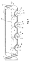
- the spray tube 2 shown in Fig. 1 according to the invention of a transport dishwasher for spraying dishes (plates, trays, dishes, cups, glasses, etc.) with liquid contains a plurality of nozzles 4, 6, 8, 10, which are arranged one after the other in the tube longitudinal direction are.
- the spray tube 2 has an inlet 12, from which liquid can flow in the tube longitudinal direction to the nozzles 4, 6, 8 and 10, and a closed tube end 13. This direction from the inlet 12 to the nozzles 4, 6, 8 and 10 is hereinafter designated as liquid supply direction 24.
- the nozzle opening 5 of at least the nozzle 12 closest to the inlet 12, preferably of two or more consecutive to the inlet 12 Next nozzles, has an outlet direction 14, which is inclined obliquely opposite to the liquid supply direction seen from the inlet 12 to the nozzles 4, 6, 8, 10 at an inclination angle ⁇ , eg ⁇ 1, ⁇ 2, ⁇ 3.
- the angle ⁇ is defined between the outlet direction 14 of the nozzle opening 5 and a theoretical transverse plane 22 which extends at right angles to the liquid feed direction 24.
- the first three nozzle openings 5, 7 and 9 following the inlet 12 have an outlet direction 14, 16 and 18, respectively, which is inclined obliquely opposite the liquid supply direction 24 at an angle ⁇ 1 or ⁇ 2 or ⁇ 3.
- These three inclined nozzle openings may all have a same inclination angle, but the inclination angle according to the preferred embodiment of the invention in the liquid supply direction 24 decreases from nozzle to nozzle, so that the inclination angle ⁇ 1 of the first nozzle opening 5 is greatest, for example between 8 ° and 16 ° is; the inclination angle ⁇ 2 of the second nozzle opening 7 is smaller and is preferably between 3 ° and 10 °; and the inclination angle ⁇ 3 of the third nozzle opening 9 is again smaller and is for example between 0 ° and 5 °.
- the nozzle openings following in the liquid feed direction preferably all have an outlet direction 20 at right angles to the liquid feed direction 24, so that here the angle of inclination ⁇ 4 lies at 0 °.
- the liquid feed direction 24 extends parallel to the axial pipe center line 26 of the spray tube 2.
- the spray tube can have over its entire length a constant inner cross section or a changing inner cross section.
- the spray tube 2 may have a circular tube cross-section or a cross-sectional shape deviating from the circular shape.
- the nozzle openings 5, 7, 9 and 11 may each have a circular opening cross-section or an opening cross-section deviating from the circular shape, for example a slot.
- the nozzle openings of the nozzles 4, 6, 8 and 10 may be in the spray tube 2 used nozzle elements with nozzle openings formed in them or according to Fig. 1 in the spray tube 2 holes formed.
- the nozzles 4, 6, 8, 10 and thus also their nozzle openings 5, 7, 9 and 11 are preferably arranged in depressions 30 of the outer surface of the spray tube 2.
- the nozzle openings 11 of the nozzles 10, which are arranged perpendicular to the liquid supply direction 24, are preferably at the lowest point of the recess 30.
- the recesses 30 are preferably concave, round or valley-like bulges in the pipe wall.
- the opening area of the nozzle opening 5, 7, 9, 11 of the nozzle or of several nozzles 4, 6, 8, 10 is closer to the inlet 12 is or is greater than that at or at the inlet 12 farther away from the nozzle or nozzles.
- the first nozzle 4 has the largest opening cross section
- the second nozzle 6 has a second largest smaller opening cross section
- the third nozzle 8 has a third largest or smaller opening cross section, etc.
- a group of two or more nozzles, which is closer to the inlet 12 have a larger opening cross-section than the following in the liquid supply direction 24 nozzle or following group of nozzles.
- the principle is to have starting from the inlet 12 gradually smaller opening cross-sections of the nozzles, at least in the initial section of the nozzle row.
- Fig. 2 shows a spray pipe 42 according to the invention, in which the nozzle openings 5 ', 7', 9 ', 11' of the nozzles 4 ', 6', 8 ', 10' are elongated holes, which in the central region 44 of its longitudinal extension on both sides preferably the same size lacing where the nozzle opening has a smaller width than in each of the two adjacent end portions 46 and 48.
- the elongated holes 5 ', 7', 9 ', 11' of the nozzles 4 ', 6', 8 ', 10' each have a length 50, a width 52 in the end regions and a constriction width 56 in the central slot area.
- the slot of the first nozzle opening 5 ' for example, a length of 12 mm, a width in the end portions 52 of 4 mm, and a Einschnürungsweite 56, for example, 3 mm.
- the second slot 7 'in the liquid feed direction 24 has, for example, an elongated hole length 50 of 12 mm, a hole width in the end regions 52 of 4 mm and a constriction width in the central region 56 of 2.5 mm.
- the third slot 9 'of the third nozzles 8' in the liquid feed direction 24 has, for example, a slot length 50 of 10 mm, a slot width in the two end areas 52 of 4 mm each and a constriction width in the central area 56 of, for example, 2.5 mm.
- the following slot of the nozzle opening 11 'of the nozzle 10' has the same dimensions as the previous nozzle opening 9 '.
- the following slots of nozzle openings for example, have a slot length 50 of 10 mm, a slot width in the end portions 52 of 4 mm, and a constriction width in the central region 56 of, for example, 2 mm.
- Fig. 3 shows a further preferred embodiment of a nozzle tube 57 of the invention, according to which the longitudinal axis 58 of the elongated holes of Fig. 2 seen in tube side view relative to the axial tube center line 26 does not include an angle of 90 ° as in Fig. 2, but a smaller angle ⁇ , for example, in the range between 85 ° and 50 °, more preferably between 65 ° and 75 °.
- the spray fan sprayed from them rotates about 90 ° relative to the slot axis 58 about the spray beam centerline.
- Fig. 4 shows schematically in longitudinal section a conveyor dishwasher according to the invention, in which a group of a plurality of upper spray tubes 2 or 42 or 57 according to the invention are arranged with their nozzles directed downwards and a lower group of spray tubes 2 or 42 or 57 after Invention are arranged with their nozzles directed upwards.
- the items to be washed 60 are transported by a transport device 62 in the transport direction 64 through the conveyor dishwasher 59.
- At the front and rear end of the spray zone 66, in which the spray tubes 2 and 42 and 57 are located, are curtains 68 and 70, z. B. in the form of rubber cloths or cloth cloth, arranged to limit the climate in the spray zone 66.
- the spray zone 66 shown may be a rotatessprühzone for cleaning items to be washed or a rinse zone for rinsing dishes.
- nozzles 4 to 10 and the nozzle openings 6 to 11 and the above-described nozzles 4 'to 10' and their nozzle openings 5 'to 11' are respectively summarized by the reference numeral 72 for ease of illustration.
- the spray pipes 2 are arranged transversely to the transport direction 64 of the washware 60 in a spray zone 66.
- the nozzle openings 72 are directed obliquely forward in the transport direction 64, unlike the vertical direction 76, as schematically illustrated by an arrow 78.
- the nozzle openings 72 deviate from the vertical direction 76 are directed counter to the transport direction 64 obliquely backwards, as schematically represented by an arrow 80.
- Fig. 4 shows an embodiment in which the Nozzle openings 72 of the intermediate spray pipes 2 (or 42 or 57) arranged between the outer upper flush pipes are aligned in the vertical direction 76.
- the spray pipes 2 (or 42 or 57) of the lower spray pipes may all be vertically aligned as shown in FIG. 4 or their first spray pipe and last spray pipe may be slightly rotated corresponding to the upper spray pipe group so that their nozzle openings 72 are inclined toward the vertical direction 76 in the direction of FIG Center of the spray zone 66 are directed, similar to the arrows 78 and 80 of the front and rear upper spray tubes.
- Fig. 5 shows schematically an end view of the transporting dishwashing machine of Fig. 4, in which liquid is conveyed from a tank 82 by means of a pump 84 to the spraying tubes 2 (or 42 or 57).
Landscapes
- Cleaning By Liquid Or Steam (AREA)
- Washing And Drying Of Tableware (AREA)
- Cleaning In General (AREA)
Applications Claiming Priority (1)
| Application Number | Priority Date | Filing Date | Title |
|---|---|---|---|
| DE102005015156A DE102005015156A1 (de) | 2005-04-02 | 2005-04-02 | Transportgeschirrspülmaschine und Sprührohr dafür |
Publications (3)
| Publication Number | Publication Date |
|---|---|
| EP1707100A2 true EP1707100A2 (fr) | 2006-10-04 |
| EP1707100A3 EP1707100A3 (fr) | 2007-08-29 |
| EP1707100B1 EP1707100B1 (fr) | 2009-09-30 |
Family
ID=36645634
Family Applications (1)
| Application Number | Title | Priority Date | Filing Date |
|---|---|---|---|
| EP06001167A Ceased EP1707100B1 (fr) | 2005-04-02 | 2006-01-20 | Lave-vaisselle à convoyeur et tube de pulvérisation associé |
Country Status (6)
| Country | Link |
|---|---|
| US (1) | US7621286B2 (fr) |
| EP (1) | EP1707100B1 (fr) |
| CN (1) | CN1839747B (fr) |
| BR (1) | BRPI0601109A (fr) |
| CA (1) | CA2537543C (fr) |
| DE (2) | DE102005015156A1 (fr) |
Cited By (1)
| Publication number | Priority date | Publication date | Assignee | Title |
|---|---|---|---|---|
| EP2110063A1 (fr) * | 2008-04-15 | 2009-10-21 | MEIKO Maschinenbau GmbH & Co. KG | Système de douille |
Families Citing this family (16)
| Publication number | Priority date | Publication date | Assignee | Title |
|---|---|---|---|---|
| DE102008047531C5 (de) * | 2008-09-16 | 2013-08-01 | Grammer Aktiengesellschaft | Halterohr für Ausstattungseinrichtungen von Fahrzeuginnenräumen sowie Verfahren und Vorrichtung zum Erzeugen einer Aussparung in einem Halterohr |
| DE102008055817A1 (de) * | 2008-11-04 | 2010-05-06 | Meiko Maschinenbau Gmbh & Co. Kg | Geschirrspülmaschine mit verbessertem Spüleffekt |
| US20110047726A1 (en) * | 2009-09-02 | 2011-03-03 | John James | Manual swimming pool cleaning apparatus employing a plurality of water jets |
| US8328953B2 (en) * | 2010-12-13 | 2012-12-11 | General Electric Company | Appliance device with motors responsive to single-phase alternating current input |
| DE102011081246B4 (de) * | 2011-08-19 | 2014-02-06 | Premark Feg L.L.C. | Spülmaschine sowie Verfahren zum automatischen Reinigen einer Spülmaschine |
| DE202013100435U1 (de) * | 2012-09-11 | 2013-02-13 | Ipek International Gmbh | System zur Videodatenübertragung in Rohrleitungen |
| US20140263759A1 (en) * | 2013-03-14 | 2014-09-18 | Millport Associates S.A. | Nozzle system and method for manufacturing composite sandwich panels |
| NO336863B1 (no) * | 2013-06-18 | 2015-11-16 | Vetco Gray Scandinavia As | Undersjøisk varmeveksler |
| USD751171S1 (en) * | 2015-01-05 | 2016-03-08 | Delta Faucet Company | Showerhead |
| CN121588977A (zh) * | 2016-10-19 | 2026-03-03 | Bw转换解决方案公司 | 喷雾喷嘴装置 |
| US11006813B2 (en) | 2018-03-21 | 2021-05-18 | Whirlpool Corporation | Dishwasher |
| CN111345761A (zh) | 2018-12-20 | 2020-06-30 | 惠而浦公司 | 洗碗机 |
| US11548017B2 (en) * | 2019-07-10 | 2023-01-10 | Kohler Co. | Showerhead |
| SE543963C2 (en) | 2020-02-28 | 2021-10-12 | Baldwin Jimek Ab | Spray applicator and spray unit comprising two groups of spray nozzles |
| US11375874B2 (en) | 2020-03-30 | 2022-07-05 | Whirlpool Corporation | Dishwasher with a dish rack and utensil caddy |
| DE202023105832U1 (de) * | 2023-10-09 | 2023-11-30 | Illinois Tool Works Inc. | Sprühvorrichtung zum Versprühen von Flüssigkeit, insbesondere Klarspülflüssigkeit, bei der Behandlung von Spülgut in einer insbesondere gewerblichen Spülmaschine sowie Spülmaschine mit einer solchen Sprühvorrichtung |
Family Cites Families (26)
| Publication number | Priority date | Publication date | Assignee | Title |
|---|---|---|---|---|
| US2270595A (en) * | 1939-01-06 | 1942-01-20 | Joseph D Lewis | Lawn sprinkler |
| US2642314A (en) * | 1951-04-14 | 1953-06-16 | Crown Zellerbach Corp | Dripless steam shower pipe |
| US3212719A (en) * | 1963-11-20 | 1965-10-19 | Corpo Dino D Di | Water curtain protective spray nozzle adapter |
| GB1435909A (en) * | 1972-12-13 | 1976-05-19 | Jwi Ltd | Spreader shower for paper making apparatus |
| US3913845A (en) * | 1972-12-31 | 1975-10-21 | Ishikawajima Harima Heavy Ind | Multihole fuel injection nozzle |
| DE2424289C3 (de) * | 1974-05-18 | 1978-04-27 | Kueppersbusch Ag, 4650 Gelsenkirchen | Bandgeschirrspülmaschine |
| DE2817813A1 (de) * | 1978-04-22 | 1979-10-25 | Licentia Gmbh | Sprueharm fuer eine geschirrspuelmaschine |
| DE3204955C2 (de) * | 1982-02-12 | 1985-04-18 | Lechler Corp., Longmeadow, Mass. | Spritzrohr mit Düsen, insbesondere Flachstrahldüsen |
| FR2567422B1 (fr) * | 1984-07-16 | 1987-05-15 | Moutarde Joseph | Procede de fabrication de rampes de lavage, notamment pour machines a laver |
| US4582259A (en) * | 1984-09-12 | 1986-04-15 | Hobart Corporation | Wash arm and method and apparatus for forming the same |
| US4735222A (en) * | 1984-09-17 | 1988-04-05 | Hobart Corporation | Spray system for a dishwashing machine |
| US4709713A (en) * | 1986-01-21 | 1987-12-01 | Kuhl Henry Y | Apparatus for conveying and washing means therefor |
| IT222678Z2 (it) * | 1991-07-09 | 1995-04-24 | Comenda Srl | Macchina lavastoviglie con dispositivo di autolavaggio |
| SE470370B (sv) | 1992-06-22 | 1994-01-31 | Pricer Norden Ab | Metod och anordning vid en prismärkningsanordning |
| JPH07502924A (ja) * | 1992-11-16 | 1995-03-30 | ウインターハルター ガストロノーム ゲーエムベーハ | 食器洗浄機 |
| US5571560A (en) * | 1994-01-12 | 1996-11-05 | Lin; Burn J. | Proximity-dispensing high-throughput low-consumption resist coating device |
| DE19535090A1 (de) * | 1995-09-21 | 1997-03-27 | Winterhalter Gastronom Gmbh | Geschirrspülmaschine für gewerbliche Zwecke |
| US5660196A (en) * | 1995-12-20 | 1997-08-26 | Oven Systems, Inc. | Quick disconnect riser pipe assembly for can washer |
| DE19608030C1 (de) * | 1996-03-02 | 1997-07-10 | Stierlen Maquet Ag | Reinigungsmaschine, insbesondere für Geschirr |
| KR100195334B1 (ko) * | 1996-08-16 | 1999-06-15 | 구본준 | 세정장치 |
| US6062056A (en) * | 1998-02-18 | 2000-05-16 | Tippins Incorporated | Method and apparatus for cooling a steel strip |
| US6269823B1 (en) * | 1998-05-04 | 2001-08-07 | Eagle-Picher Industries, Inc. | Can washing apparatus with plastic risers |
| EP0980668A3 (fr) * | 1998-08-18 | 2002-05-22 | Epenhuysen Chemie N.V. | Méthode pour délivrer un liquide, méthode pour générer de la mousse et dispositif mettant en oeuvre une telle méthode |
| CN2472819Y (zh) * | 2000-11-16 | 2002-01-23 | 卜云泽 | 一种球形灌溉喷嘴 |
| CN1317081C (zh) * | 2003-12-26 | 2007-05-23 | 中芯国际集成电路制造(上海)有限公司 | 一种旋转式喷头流量调整装置 |
| CN1695818A (zh) * | 2004-05-15 | 2005-11-16 | 鸿富锦精密工业(深圳)有限公司 | 冲洗喷嘴和洗净设备 |
-
2005
- 2005-04-02 DE DE102005015156A patent/DE102005015156A1/de not_active Withdrawn
-
2006
- 2006-01-20 DE DE502006004954T patent/DE502006004954D1/de not_active Expired - Lifetime
- 2006-01-20 EP EP06001167A patent/EP1707100B1/fr not_active Ceased
- 2006-02-22 CA CA002537543A patent/CA2537543C/fr not_active Expired - Fee Related
- 2006-03-17 CN CN2006100653380A patent/CN1839747B/zh not_active Expired - Fee Related
- 2006-03-27 US US11/389,939 patent/US7621286B2/en not_active Expired - Fee Related
- 2006-03-30 BR BRPI0601109-8A patent/BRPI0601109A/pt not_active IP Right Cessation
Cited By (1)
| Publication number | Priority date | Publication date | Assignee | Title |
|---|---|---|---|---|
| EP2110063A1 (fr) * | 2008-04-15 | 2009-10-21 | MEIKO Maschinenbau GmbH & Co. KG | Système de douille |
Also Published As
| Publication number | Publication date |
|---|---|
| US7621286B2 (en) | 2009-11-24 |
| DE102005015156A1 (de) | 2006-10-05 |
| CA2537543C (fr) | 2009-12-01 |
| CN1839747A (zh) | 2006-10-04 |
| DE502006004954D1 (de) | 2009-11-12 |
| EP1707100A3 (fr) | 2007-08-29 |
| US20060219820A1 (en) | 2006-10-05 |
| CA2537543A1 (fr) | 2006-10-02 |
| EP1707100B1 (fr) | 2009-09-30 |
| CN1839747B (zh) | 2010-05-12 |
| BRPI0601109A (pt) | 2006-12-05 |
Similar Documents
| Publication | Publication Date | Title |
|---|---|---|
| EP1707100B1 (fr) | Lave-vaisselle à convoyeur et tube de pulvérisation associé | |
| EP2593600B1 (fr) | Diffuseur pour le nottoyage d'un composant charge de peluches | |
| DE975953C (de) | Foerderband fuer Geschirrwaschmaschinen | |
| DE102012016398B4 (de) | Düseneinrichtung für einen Sprüharm einer Geschirrspülmaschine | |
| EP2601878B1 (fr) | Lave-vaisselle avec inversion automatique du sens de rotation du bras pulvérisateur | |
| EP1671574B1 (fr) | Support de vaisselle pour lave-vaisselle | |
| EP2117408B1 (fr) | Filtre pour des machines à laver | |
| EP2556781A1 (fr) | Agencement de bras pulvérisateur d'un lave-vaisselle | |
| DE102011088494A1 (de) | Sprüharm einer Geschirrspülmaschine | |
| EP3747338A1 (fr) | Panier pour laves-vaisselles | |
| DE1503792A1 (de) | Spruehvorrichtung fuer automatische Geschirrspuelmaschinen | |
| EP1345526A1 (fr) | Dispositif destine a ameliorer la capacite de sechage d'un lave-vaisselle | |
| AT522471B1 (de) | Spülkorb für Spülmaschinen | |
| EP3586713B1 (fr) | Bras pulvérisateur pour un lave-vaisselle | |
| EP3747340B1 (fr) | Panier pour laves-vaisselles | |
| EP3815595B1 (fr) | Machine à laver la vaisselle dotée bande transporteuse | |
| EP3120747B1 (fr) | Système de lavage pour un lave-vaisselle et lave-vaisselle doté d'un tel système de lavage | |
| DE102014111319A1 (de) | Spülkorb für einen Spülautomaten | |
| EP4537731A1 (fr) | Dispositif de pulvérisation pour pulvériser un liquide, en particulier un liquide de rinçage, dans le traitement d'articles à laver dans un lave-vaisselle industriel, et lave-vaisselle équipé d'un tel dispositif de pulvérisation | |
| EP0184037B1 (fr) | Dispositif de transport pneumatique pourvu d'un filtre | |
| WO2011018139A1 (fr) | Machine de nettoyage pour bouteilles ou récipients similaires | |
| DE102007016331A1 (de) | Transportvorrichtung für eine Durchlaufspülmaschine mit einer Vorrichtung zur Abgabe eines fluiden Mediums, Durchlaufspülmaschine und Verfahren zum Reinigen von Spülgut | |
| CH426128A (de) | Spritzdüse | |
| WO2023117615A1 (fr) | Dispositif de nettoyage | |
| DE102024132061A1 (de) | Spülmaschine mit waschsystem und reinigungsöffnung |
Legal Events
| Date | Code | Title | Description |
|---|---|---|---|
| PUAI | Public reference made under article 153(3) epc to a published international application that has entered the european phase |
Free format text: ORIGINAL CODE: 0009012 |
|
| 17P | Request for examination filed |
Effective date: 20060120 |
|
| AK | Designated contracting states |
Kind code of ref document: A2 Designated state(s): AT BE BG CH CY CZ DE DK EE ES FI FR GB GR HU IE IS IT LI LT LU LV MC NL PL PT RO SE SI SK TR |
|
| AX | Request for extension of the european patent |
Extension state: AL BA HR MK YU |
|
| PUAL | Search report despatched |
Free format text: ORIGINAL CODE: 0009013 |
|
| AK | Designated contracting states |
Kind code of ref document: A3 Designated state(s): AT BE BG CH CY CZ DE DK EE ES FI FR GB GR HU IE IS IT LI LT LU LV MC NL PL PT RO SE SI SK TR |
|
| AX | Request for extension of the european patent |
Extension state: AL BA HR MK YU |
|
| RIC1 | Information provided on ipc code assigned before grant |
Ipc: A47L 15/14 20060101ALI20070723BHEP Ipc: A47L 15/16 20060101AFI20060717BHEP Ipc: A47L 15/24 20060101ALI20070723BHEP |
|
| 17Q | First examination report despatched |
Effective date: 20071017 |
|
| AKX | Designation fees paid |
Designated state(s): DE FR GB IT |
|
| GRAP | Despatch of communication of intention to grant a patent |
Free format text: ORIGINAL CODE: EPIDOSNIGR1 |
|
| GRAS | Grant fee paid |
Free format text: ORIGINAL CODE: EPIDOSNIGR3 |
|
| GRAA | (expected) grant |
Free format text: ORIGINAL CODE: 0009210 |
|
| AK | Designated contracting states |
Kind code of ref document: B1 Designated state(s): DE FR GB IT |
|
| REG | Reference to a national code |
Ref country code: GB Ref legal event code: FG4D Free format text: NOT ENGLISH |
|
| REF | Corresponds to: |
Ref document number: 502006004954 Country of ref document: DE Date of ref document: 20091112 Kind code of ref document: P |
|
| PLBE | No opposition filed within time limit |
Free format text: ORIGINAL CODE: 0009261 |
|
| STAA | Information on the status of an ep patent application or granted ep patent |
Free format text: STATUS: NO OPPOSITION FILED WITHIN TIME LIMIT |
|
| 26N | No opposition filed |
Effective date: 20100701 |
|
| REG | Reference to a national code |
Ref country code: FR Ref legal event code: PLFP Year of fee payment: 11 |
|
| REG | Reference to a national code |
Ref country code: FR Ref legal event code: PLFP Year of fee payment: 12 |
|
| REG | Reference to a national code |
Ref country code: FR Ref legal event code: PLFP Year of fee payment: 13 |
|
| PGFP | Annual fee paid to national office [announced via postgrant information from national office to epo] |
Ref country code: IT Payment date: 20190123 Year of fee payment: 14 Ref country code: DE Payment date: 20190129 Year of fee payment: 14 Ref country code: FR Payment date: 20190125 Year of fee payment: 14 Ref country code: GB Payment date: 20190128 Year of fee payment: 14 |
|
| REG | Reference to a national code |
Ref country code: DE Ref legal event code: R119 Ref document number: 502006004954 Country of ref document: DE |
|
| GBPC | Gb: european patent ceased through non-payment of renewal fee |
Effective date: 20200120 |
|
| PG25 | Lapsed in a contracting state [announced via postgrant information from national office to epo] |
Ref country code: DE Free format text: LAPSE BECAUSE OF NON-PAYMENT OF DUE FEES Effective date: 20200801 Ref country code: GB Free format text: LAPSE BECAUSE OF NON-PAYMENT OF DUE FEES Effective date: 20200120 Ref country code: FR Free format text: LAPSE BECAUSE OF NON-PAYMENT OF DUE FEES Effective date: 20200131 |
|
| PG25 | Lapsed in a contracting state [announced via postgrant information from national office to epo] |
Ref country code: IT Free format text: LAPSE BECAUSE OF NON-PAYMENT OF DUE FEES Effective date: 20200120 |