EP1715733A2 - Dispositif d'alimentation de composants électriques, système de montage et ses procédés de montage - Google Patents
Dispositif d'alimentation de composants électriques, système de montage et ses procédés de montage Download PDFInfo
- Publication number
- EP1715733A2 EP1715733A2 EP20060101416 EP06101416A EP1715733A2 EP 1715733 A2 EP1715733 A2 EP 1715733A2 EP 20060101416 EP20060101416 EP 20060101416 EP 06101416 A EP06101416 A EP 06101416A EP 1715733 A2 EP1715733 A2 EP 1715733A2
- Authority
- EP
- European Patent Office
- Prior art keywords
- control device
- parameters
- placement
- control
- display device
- Prior art date
- Legal status (The legal status is an assumption and is not a legal conclusion. Google has not performed a legal analysis and makes no representation as to the accuracy of the status listed.)
- Withdrawn
Links
- 238000000034 method Methods 0.000 title claims abstract description 24
- 239000000758 substrate Substances 0.000 claims abstract description 8
- 230000007547 defect Effects 0.000 claims description 20
- 230000008878 coupling Effects 0.000 claims description 6
- 238000010168 coupling process Methods 0.000 claims description 6
- 238000005859 coupling reaction Methods 0.000 claims description 6
- 239000004973 liquid crystal related substance Substances 0.000 claims description 4
- 230000003287 optical effect Effects 0.000 claims description 4
- 230000005540 biological transmission Effects 0.000 claims description 3
- 239000011295 pitch Substances 0.000 description 6
- 230000008859 change Effects 0.000 description 4
- 230000011664 signaling Effects 0.000 description 3
- 230000000694 effects Effects 0.000 description 2
- 230000007257 malfunction Effects 0.000 description 2
- 230000008569 process Effects 0.000 description 2
- 238000013024 troubleshooting Methods 0.000 description 2
- 230000001419 dependent effect Effects 0.000 description 1
- 238000001514 detection method Methods 0.000 description 1
- 230000002349 favourable effect Effects 0.000 description 1
- 230000007246 mechanism Effects 0.000 description 1
- 230000001681 protective effect Effects 0.000 description 1
- 230000001960 triggered effect Effects 0.000 description 1
Images

Classifications
-
- B—PERFORMING OPERATIONS; TRANSPORTING
- B60—VEHICLES IN GENERAL
- B60R—VEHICLES, VEHICLE FITTINGS, OR VEHICLE PARTS, NOT OTHERWISE PROVIDED FOR
- B60R16/00—Electric or fluid circuits specially adapted for vehicles and not otherwise provided for; Arrangement of elements of electric or fluid circuits specially adapted for vehicles and not otherwise provided for
- B60R16/02—Electric or fluid circuits specially adapted for vehicles and not otherwise provided for; Arrangement of elements of electric or fluid circuits specially adapted for vehicles and not otherwise provided for electric constitutive elements
- B60R16/0207—Wire harnesses
- B60R16/0215—Protecting, fastening and routing means therefor
- B60R16/0222—Grommets
-
- H—ELECTRICITY
- H05—ELECTRIC TECHNIQUES NOT OTHERWISE PROVIDED FOR
- H05K—PRINTED CIRCUITS; CASINGS OR CONSTRUCTIONAL DETAILS OF ELECTRIC APPARATUS; MANUFACTURE OF ASSEMBLAGES OF ELECTRICAL COMPONENTS
- H05K13/00—Apparatus or processes specially adapted for manufacturing or adjusting assemblages of electric components
- H05K13/04—Mounting of components, e.g. of leadless components
- H05K13/0417—Feeding with belts or tapes
-
- H—ELECTRICITY
- H05—ELECTRIC TECHNIQUES NOT OTHERWISE PROVIDED FOR
- H05K—PRINTED CIRCUITS; CASINGS OR CONSTRUCTIONAL DETAILS OF ELECTRIC APPARATUS; MANUFACTURE OF ASSEMBLAGES OF ELECTRICAL COMPONENTS
- H05K13/00—Apparatus or processes specially adapted for manufacturing or adjusting assemblages of electric components
- H05K13/04—Mounting of components, e.g. of leadless components
- H05K13/0417—Feeding with belts or tapes
- H05K13/0419—Feeding with belts or tapes tape feeders
Definitions
- the invention relates to a feeding device for electrical components, a placement system comprising such a feeder, and associated control processes for the feeder, the placement system and a placement for such a feeder.
- An automatic placement machine for equipping substrates with electrical components usually comprises a conveyor belt via which the substrates to be loaded are transported to the placement locations of the placement machine.
- the side of the transport route is usually provided in a pick-up area of the placement machine a plurality of parking spaces for coupling feeders for electrical components to the placement.
- An assembly head of the placement machine is moved by a two-dimensional positioning system between the pick-up area, in which the electrical components are supplied by the feeders, and the placement locations at which the substrates to be loaded are provided.
- the feeders Due to the miniaturization of the electrical components, the feeders also have very small widths, whereby the number and density of arranged in the pickup area of the placement machine feeders are getting higher.
- the distance between the individual parking spaces is adapted to the width of the narrowest feeders.
- wider feeders which cover several parking spaces in the coupled state, is no longer clearly visible to the machine operator, which pitch the feeder is specifically assigned.
- the machine operator can therefore inform himself directly at the feeder about operational parameters relating to the feeder.
- a clear assignment of the output information to the associated feeder is automatically given.
- the alphanumeric display device also allows the representation of a virtually unlimited number of operational parameters, which greatly improves the information capabilities for the machine operator. Especially with feeders with a high number of flexibly adjustable operating parameters results This results in an increased ease of use and operational safety.
- the feeder can be designed according to claim 2 to the effect that it comprises a control panel, by means of which the parameters displayed by the display device are arbitrarily selectable. This allows the operator to quickly display the information he needs from a variety of available parameters via the alphanumeric display.
- control panel is configured such that the machine operator via the control panel operation-relevant parameters such as delivery distance, constructivetaktzeit, etc., can change directly. Characterized in that the operating parameter to be changed is displayed simultaneously by the alphanumeric display device, a direct control over the changes made possible. Changed parameters are stored in the control device. Since the control panel is provided directly on the feeder, it is also ensured that the changes made to the operating parameters also apply to the desired feeder, so that no assignment errors can occur. This results in an increased user-friendliness and operational safety.
- one of the parameters represented by the display device is an identifier for the arrangement position of the feed device on the placement machine. This can be for example to act the number of the parking space in the pick-up area of the placement, where the feeder is coupled to the placement. The machine operator can thus inform himself at any time about the correct position of the feed device on the placement machine. Possible allocation errors, such as occur in a large number of very tightly arranged feeders on the placement machine or when using feeders that extend over several parking spaces, are thereby prevented.
- One of the parameters represented by the display device can specify a functional state of the feed device according to an embodiment according to claim 6.
- the machine operator can be informed, for example, whether the feeder is fully functional or a defect exists.
- a possibly present defect can be displayed in plain text, whereby the operator can inform very quickly about the nature of the defect and no loss of time due to troubleshooting.
- the feeder is designed according to claim 7 to the effect that the display optionally represent the parameters in different orientations can.
- the display orientation can therefore be adapted to the conditions of the parking space at which the feeder is coupled to the placement, so that the display is easy to read from a favorable for the operator viewing position.
- the alphanumeric display device is realized by a multi-digit liquid crystal display.
- the liquid crystal display allows a very flexible plain text display and is also still inexpensive.
- a control method relates to a feeder having the features of claim 1, wherein upon the occurrence of a defect of the feeder, the type of defect is displayed by the display means. This informs the machine operator about the nature of the defect immediately after the defect has occurred, thereby largely eliminating time-consuming troubleshooting.
- the feed device furthermore has an optical or acoustic signal device by means of which the machine operator is made aware of the defect.
- the operator knows immediately at which feeder there is a defect and is informed by the display device about the nature of the error.
- the defect can be remedied much faster and possible downtimes are significantly shortened.
- a control method relates to a placement machine having a first control device and at least one parking space for coupling a feed device according to the invention with the features of claim 1, wherein each parking space has a data interface connected to the first control device of the placement to data with the second control device to replace a coupled feeder.
- the method is characterized in that the first control device of the placement detects a coupled to one of the locations feeder and transmits operational parameters to the second control device of the feeder, so that they can be displayed by the display device.
- the control method is designed for a placement machine, which has several parking spaces, according to claim 12 in that one of the first control device of the placement to the second control device of the feeder transmitted parameters a unique parking space identifier for the parking space at which the respective feeder at the placement is coupled. Due to the fact that the first control device assigned to the placement machine transmits the correct and unambiguous parking space identification to the feed device, assignment errors are ruled out. The machine operator can therefore find out immediately after coupling about the correct parking space of the feeder. Under the parking space identification is, for example, the number of parking space at which the feeder is coupled to the placement, and in addition possibly an identifier for the respective pickup area in which the parking space is located to understand.
- An assembly system comprises a placement machine having a first control device and a plurality of locations arranged in different pick-up areas of the placement machines for feeders, each pitch one with the first control device of the placement has connected data interface to allow data exchange with a second control device of a coupled to the placement feeder. Furthermore, the placement system comprises at least one coupled to one of the slots of the placement machine feeder with the features of claim 1. With regard to the advantages of Be Divisionsystems reference is made to the advantages mentioned in claim 1.
- the alphanumeric display device of the feeder is configured such that the parameters are selectively displayed in different orientations, i. at least two orientations can be represented.
- the advantages of this embodiment reference is made to claim 7.
- a control method relates to a placement system according to claim 14, wherein in a first step, the first control device of the placement a clear area identifier for the pickup area, in which the respective feed device is coupled, is transmitted to the second control device of the feeder.
- the second control device or the display device of the feed device represents all parameters in the orientation assigned to the transmitted area code.
- each area code which stands for a specific pickup area at the placement machine is assigned a specific orientation of the presentation of the parameters at the feeder .
- the control device can therefore, depending on the pick-up area in which the feed device is located, select the orientation of the parameters shown in such a way that, for example, an optimal readability results for the machine operator.
- the feeding device is accessible only from a certain side due to the structural conditions of the placement in the various pick-up areas or the display of only one particular Viewing position is clearly legible. This ensures that the orientation of the representation of the parameters by the display device are optimally adapted to the circumstances of the pick-up area such that the parameters can be read by the machine operator quickly and without error. This not only increases the ease of use, but also the reliability, as reading errors are significantly reduced.
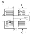
- the placement system 1 consists of a placement machine 2 for equipping substrates 5 with electrical components and at least one feed device 3 according to the invention, the nature of which will be discussed in more detail below in connection with FIG.
- the placement machine 2 comprises a transport path 4, for example in the form of a conveyor belt, on which the substrates 5 to be loaded are brought to placement locations of the placement machine 2 and are transported away again after placement.
- the placement machine 2 on four pick-up areas (I, II, III, IV), on each of which several parking spaces 7 are provided for feeders 3.
- Each parking space 7 has a data interface 8, to which a feeder 3 can be coupled to the placement machine 2.
- the placement machine 2 is further associated with a first control device 9, which is located, for example, at a suitable location of a chassis of the placement machine 2. All parking spaces 7, more precisely the data interfaces 8 of the parking spaces 7, are electrically connected to the first control device 9 via electrical lines 10 (shown by dashed lines in FIG. 1). For example, it makes sense to connect the parking spaces 7 by means of a fieldbus (CAN bus) with the first control device 9.
- a fieldbus CAN bus
- the placement machine 2 further comprises a cross member 11 which spans the transport path 4 like a bridge.
- two-dimensional positioning systems 12 for placement heads 14 of the placement machines 2 are arranged on the support 11.
- the placement heads 14 in a parallel to the transport path 4 level between the pick-up areas (I, II, III, IV), in which the electrical components are provided by feeders 3, and the Be Division responsibilityn 6, where the Stocking substrates 5 are provided, are moved.
- FIG. 2 is a schematic, not to scale representation of the feed device 3 and only the components of the feed device 3 necessary for explaining the invention are shown.
- a second control device 15 is provided which controls the processes affecting the feeder 3 and stores data.
- the control device consists of a computer unit (CPU) and a memory unit associated with the computer unit, in which data can be stored and retrieved.
- an alphanumeric display device 16 is provided, which is connected to the second control device 15 via an electrical line 17 (shown in phantom in FIG. 2).
- the display device 16 which can advantageously be a multi-digit liquid crystal display, serves, in particular, to display operating parameters of the control device.
- the operating parameters include, inter alia, identifiers for the pick-up area or the parking space 7, to which the feeder 3 is attached to the placement machine 2, as well as error entries, type and number of subsidized components, the feed length and the feed stroke time of the conveying mechanism, not shown.
- the feeding device 3 can furthermore have a control panel 18, which is advantageously arranged next to the display device 16.
- the control panel 18, which has one or more keys 19, is also connected via an electrical line 17 to the control device and serves to select the parameters represented by the display device 16.
- the operator 20 can thus by instructions of the keys 19 on the control panel 18 of the second control device 15 instructions, which parameters are to be displayed on the display device 16.
- certain operating parameters (such as, for example, the feed stroke time or the feed length) relating to the feed device 3 can not only be displayed by actuation of the control panel, but also directly changed. This makes it possible for the machine operator 20 to change the functionalities of the feeder 3 and thus adapt to new conditions. This is necessary, for example, if another Type of components to be funded by the feeder 3.
- the feeding device 3 as shown in Figure 2, a signaling device 21 which shows extraordinary events, such as a defect of the feeder 3, either acoustically and / or visually the operator 20. Also, the signaling device 21 is electrically connected to the second control device 15.
- each parking space 7 of the feed devices 3 on the placement machine 2 comprises a data interface 8 to which the feed device 3 can be coupled.
- a contact element 23 such as a plug, which is connected to the second control device 15. If such a feed device 3 is coupled to a parking space 7 of the placement machine 2 shown in FIG. 1, then the first control device 9 of the placement machine 2 is electrically connected via the data interface 8 and the contact element 23 to the second control device 15 of the feed device 3, so that a data exchange between the first and the second control device 15 is possible.
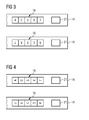
- the display device 16 is configured in such a way or can be controlled by the second control device 15 such that the displayed parameters can be displayed in different orientations.
- the orientation of the display is chosen so that it is readable from a particular viewing direction.
- the control device can also change the orientation of the display so that, as in the lower part of FIG. 3, it can be read from the opposite viewing position.
- the display device 16 may be further configured to simultaneously display one or more parameters.
- one of the parameters indicates the functional state of the feed device 3. Under the functional state, for example, the operational readiness, a malfunction, the initialization of the second control device 15, the booting of a control program, etc. understood.
- the type of defect is immediately displayed by the second control device 15 by means of the display device 16. This is done without regard to the previously displayed parameters, which are replaced by the information about the nature of the defect. If, as in the exemplary embodiment illustrated in FIG. 2, the feed device 3 has a signal device 21, after detection of a defect, an optical and / or acoustic warning signal is triggered by the second control device 15 by means of the signal device 21. Thus, the operator 20 is alerted very quickly to the presence of the defect.
- a plurality of feeders 3 at the parking spaces of the placement machine 2 coupled consisting of a placement machine 2 and a feed device 3 according to the invention.
- data interfaces 8 By located at each of the slots 7 data interfaces 8 is a data exchange between the first control device 9 of the placement machine 2 and the second control device 15 of a coupled feeder 3 is possible.
- the individual pitches 7 are electrically scanned at certain intervals to detect whether the pitches 7 are each occupied or vacant, ie whether a feeder 3 is coupled or not.
- the first control device 9 If the first control device 9 recognizes the presence of a feed device 3, then it can transmit operating-relevant parameters to the second control device 15 of the feed device 3 via the data interface 8 so that it can be displayed by the display device 16 of the control device.
- the parameters are either displayed directly or stored in the memory unit of the second control device 15 so that they can be displayed by the display device 16 as required.
- one of the parameters transmitted from the first to the second control device 15 is an unambiguous parking space identifier for the parking space 7, to which the respective feed device 3 is coupled to the placement machine 2.
- the transmitted parking space identification can be either the number of the parking space directly or an encrypted identification code, which must first be interpreted by the second control device 15 into a parking space number. After the transmission of the parking space identifier, this can be displayed by the second control device 15 by means of the display device 16. This is particularly advantageous if the number and density of the coupled to the placement 2 feeders 3 are very large. Thus, the machine operator 20 is informed directly to the feeders 3 about which pitch 7 on the placement machine 2 is. Errors in the assignment of the feeders 3 to the Be Published conference 6 are therefore excluded.
- the spacing of the parking spaces 7 at the placement machine 2 is selected so that even the narrowest feeders 3 can be coupled directly next to one another at the placement machine 2.
- the feeding device 3 is designed significantly wider according to the width of the supplied component, and therefore occupied in the width of several parking spaces 7. In this case, however, it is not readily apparent to the operator 20 at which location 7, i. at which data interface 8, this wider feeder 3 is actually coupled to the placement machine 2.
- the parking space identification or the parking space number can be read directly on the display device 16 of the respective feed device 3, assignment errors are prevented from the outset.
- the display device 16 of the feed device 3 is designed such that the orientation of the displayed parameters can be changed.
- Such functionality of the feeder 3 is particularly advantageous in placement systems, which have a plurality of pick-up areas in which pitches 7 are provided for feeders 3. Due to the structural conditions of the placement system 1, the feeders 3, depending on which in which pick-up area they are arranged, accessible from the machine operator 20 from different directions. This is also often the case because the feeders 3 and the pick-up areas are covered by a protective hood 24, which must first be folded away by the machine operator 20 in order to gain access to the feeders 3. As can be seen from FIG. 1, the directions with which a machine operator 20 (shown in FIG.
- the first control device 9 of the placement machine 2 transmits via the data interface 8 of the parking space to which the feed device 3 is coupled to the placement machine 2, an area identifier for the pick-up area in which the respective feed device 3 is located.
- the area identifier which precisely defines the pick-up area is supplied to the second control device 15 of the feeder 3. This decides, depending on the area identifier, with which orientation the parameters represented by the display device 16 are displayed in order to ensure optimum readability for the machine operator 20. Not only does this increase user-friendliness, it also significantly reduces the risk of reading errors.
- the parking spaces 7 or the data and energy interfaces for the feeders 3 are arranged directly on the placement machine 2.
- the concept of the invention is not limited to this embodiment, but also applies to an embodiment in which the feeders 3 are arranged on a mobile means of transport, so moved up to the placement 2 and coupled with this.
Landscapes
- Engineering & Computer Science (AREA)
- Manufacturing & Machinery (AREA)
- Microelectronics & Electronic Packaging (AREA)
- Mechanical Engineering (AREA)
- Supply And Installment Of Electrical Components (AREA)
- Automatic Assembly (AREA)
Applications Claiming Priority (1)
| Application Number | Priority Date | Filing Date | Title |
|---|---|---|---|
| DE200510007064 DE102005007064A1 (de) | 2005-02-16 | 2005-02-16 | Zuführeinrichtung für elektrische Bauelemente, Bestücksystem und zugehörige Steuerverfahren |
Publications (2)
| Publication Number | Publication Date |
|---|---|
| EP1715733A2 true EP1715733A2 (fr) | 2006-10-25 |
| EP1715733A3 EP1715733A3 (fr) | 2007-05-30 |
Family
ID=36776120
Family Applications (1)
| Application Number | Title | Priority Date | Filing Date |
|---|---|---|---|
| EP20060101416 Withdrawn EP1715733A3 (fr) | 2005-02-16 | 2006-02-08 | Dispositif d'alimentation de composants électriques, système de montage et ses procédés de montage |
Country Status (2)
| Country | Link |
|---|---|
| EP (1) | EP1715733A3 (fr) |
| DE (1) | DE102005007064A1 (fr) |
Cited By (3)
| Publication number | Priority date | Publication date | Assignee | Title |
|---|---|---|---|---|
| WO2015040082A3 (fr) * | 2013-09-18 | 2015-06-18 | Mycronic AB | Procédé, système et dispositif de fourniture d'informations à un opérateur d'un système smt |
| WO2016131967A1 (fr) * | 2015-02-19 | 2016-08-25 | Mycronic AB | Procédé, système et dispositif de fourniture d'informations sur un dispositif d'affichage agencé sur un support dans un système de technologie à montage en surface |
| WO2016189059A3 (fr) * | 2015-05-28 | 2017-01-12 | Mycronic AB | Récipients et/ou boîtes intelligents manipulés par un entrepôt smd automatisé et stockés dans ce dernier |
Families Citing this family (1)
| Publication number | Priority date | Publication date | Assignee | Title |
|---|---|---|---|---|
| EP3826447A1 (fr) * | 2019-11-21 | 2021-05-26 | Mycronic AB | Guide de bande pour guider un composant de bande comprenant une partie transparente |
Citations (4)
| Publication number | Priority date | Publication date | Assignee | Title |
|---|---|---|---|---|
| JPH0738285A (ja) * | 1993-07-16 | 1995-02-07 | Matsushita Electric Ind Co Ltd | 部品供給装置 |
| US20030219330A1 (en) * | 2001-05-24 | 2003-11-27 | Lyndaker David W. | Auto-loading component tape feeder |
| JP2004047572A (ja) * | 2002-07-09 | 2004-02-12 | Yamagata Casio Co Ltd | 部品供給フィーダ、部品実装装置、部品実装システム、及び装着確認方法 |
| JP2004047858A (ja) * | 2002-07-15 | 2004-02-12 | Yamaha Motor Co Ltd | 部品実装装置 |
Family Cites Families (5)
| Publication number | Priority date | Publication date | Assignee | Title |
|---|---|---|---|---|
| JPH066084A (ja) * | 1992-06-19 | 1994-01-14 | Olympus Optical Co Ltd | 電子部品自動実装機 |
| JP3802953B2 (ja) * | 1996-10-04 | 2006-08-02 | 富士機械製造株式会社 | フィーダおよび回路部品供給システム |
| JP4117859B2 (ja) * | 1998-06-24 | 2008-07-16 | 富士機械製造株式会社 | 部品供給ユニット |
| US6449523B1 (en) * | 1999-10-15 | 2002-09-10 | Data I/O Corporation | Feeder/programming/buffer operating system |
| DE10226983A1 (de) * | 2001-09-12 | 2003-03-27 | Roland Smyczek | Vorrichtung zum Bestücken von Gegenständen mit Bauelementen und Verfahren zum Wechseln von Federn bei einer solchen Vorrichtung |
-
2005
- 2005-02-16 DE DE200510007064 patent/DE102005007064A1/de not_active Withdrawn
-
2006
- 2006-02-08 EP EP20060101416 patent/EP1715733A3/fr not_active Withdrawn
Patent Citations (4)
| Publication number | Priority date | Publication date | Assignee | Title |
|---|---|---|---|---|
| JPH0738285A (ja) * | 1993-07-16 | 1995-02-07 | Matsushita Electric Ind Co Ltd | 部品供給装置 |
| US20030219330A1 (en) * | 2001-05-24 | 2003-11-27 | Lyndaker David W. | Auto-loading component tape feeder |
| JP2004047572A (ja) * | 2002-07-09 | 2004-02-12 | Yamagata Casio Co Ltd | 部品供給フィーダ、部品実装装置、部品実装システム、及び装着確認方法 |
| JP2004047858A (ja) * | 2002-07-15 | 2004-02-12 | Yamaha Motor Co Ltd | 部品実装装置 |
Cited By (7)
| Publication number | Priority date | Publication date | Assignee | Title |
|---|---|---|---|---|
| WO2015040082A3 (fr) * | 2013-09-18 | 2015-06-18 | Mycronic AB | Procédé, système et dispositif de fourniture d'informations à un opérateur d'un système smt |
| US10640290B2 (en) | 2013-09-18 | 2020-05-05 | Mycronic AB | Method, system and device for providing information to an SMT system operator |
| WO2016131967A1 (fr) * | 2015-02-19 | 2016-08-25 | Mycronic AB | Procédé, système et dispositif de fourniture d'informations sur un dispositif d'affichage agencé sur un support dans un système de technologie à montage en surface |
| CN112004398A (zh) * | 2015-02-19 | 2020-11-27 | 迈康尼股份公司 | 用于在表面安装技术系统中提供信息的方法、系统和装置 |
| US10956857B2 (en) | 2015-02-19 | 2021-03-23 | Mycronic AB | Method, system and device for providing information on a display arranged on a carrier in a surface mount technology system |
| WO2016189059A3 (fr) * | 2015-05-28 | 2017-01-12 | Mycronic AB | Récipients et/ou boîtes intelligents manipulés par un entrepôt smd automatisé et stockés dans ce dernier |
| US10694646B2 (en) | 2015-05-28 | 2020-06-23 | Mycronic AB | Smart containers and/or boxes handled by, and stored in, automated SMD warehouse |
Also Published As
| Publication number | Publication date |
|---|---|
| EP1715733A3 (fr) | 2007-05-30 |
| DE102005007064A1 (de) | 2006-08-24 |
Similar Documents
| Publication | Publication Date | Title |
|---|---|---|
| DE69806123T2 (de) | Verfahren zum zuführen von bauelementen, verfahren zum formen von bauteilanordnungsdaten und die diese verfahren verwendende bestückungsvorrichtung für elektronische bauteile | |
| EP3405351B1 (fr) | Dispositif de marquage pour composants électriques | |
| EP0563684A2 (fr) | Procédé de surveillance et système d'observation pour un processus technique | |
| DE10339945B4 (de) | Elektrischer Verteilerkasten und Verfahren zum Abschneiden von Drähten | |
| EP2250021B1 (fr) | Cartouche d encre avec élément de carte de circuit imprimé | |
| EP2510412B1 (fr) | Module électronique | |
| DE112020006433T5 (de) | Teilemontagesystem und Teilemontageverfahren | |
| DE112006001104T5 (de) | Trägerbandeinheit zum Zuführen elektronischer Komponenten, Vorrichtung zum Zuführen elektronischer Komponenten, Verfahren zum Verwalten von Komponenteninformationen in einer Vorrichtung zum Zuführen elektronischer Komponenten, Bestückungsvorrichtung elektronischer Komponenten und Verfahren zum Verwalten von Komponenteninformationen in einer Bestückungsvorrichtung elektronischer Komponenten | |
| DE102009043642A1 (de) | Verfahren zum Bestücken von Leiterplatten mit Bauelementen | |
| EP1715733A2 (fr) | Dispositif d'alimentation de composants électriques, système de montage et ses procédés de montage | |
| EP1576867B1 (fr) | Carte orientee processus a integration et extension modulaire d'automate programmable | |
| EP0187876A1 (fr) | Système d'installation pour ascenseur | |
| EP1728131A2 (fr) | Appareil electrique de terrain | |
| EP3024312A2 (fr) | Procede d'equipement de circuits imprimes | |
| DE102016117385B4 (de) | Einrichtung und Verfahren zur Identifikation von elektronischen Baugruppen | |
| DE112008002583T5 (de) | Montagesystem für elektronische Bauelemente und Montagemaschine für elektronische Bauelemente | |
| EP0905828A2 (fr) | Dispositif d'identification des appareils électroniques | |
| DE102013100770A1 (de) | Motorsteuervorrichtung | |
| DE102016105522B4 (de) | Anzeigeeinheit | |
| EP1396569B1 (fr) | Système programmable de machine à coudre | |
| LU504361B1 (de) | Sektionsbaugruppe für Kablier- und/oder Zwirnmaschine | |
| EP4351976B1 (fr) | Dispositif d'application d'étiquettes sur une pièce | |
| EP3322654B1 (fr) | Dispositif de convoyage pour le transport de produits individuels | |
| DE10304526B4 (de) | Vorrichtung und Verfahren zur Zuweisung von Feldbusadressen | |
| DE19927498A1 (de) | System und Verfahren zur Qualitätskontrolle in einer Produktionslinie |
Legal Events
| Date | Code | Title | Description |
|---|---|---|---|
| PUAI | Public reference made under article 153(3) epc to a published international application that has entered the european phase |
Free format text: ORIGINAL CODE: 0009012 |
|
| AK | Designated contracting states |
Kind code of ref document: A2 Designated state(s): AT BE BG CH CY CZ DE DK EE ES FI FR GB GR HU IE IS IT LI LT LU LV MC NL PL PT RO SE SI SK TR |
|
| AX | Request for extension of the european patent |
Extension state: AL BA HR MK YU |
|
| PUAL | Search report despatched |
Free format text: ORIGINAL CODE: 0009013 |
|
| AK | Designated contracting states |
Kind code of ref document: A3 Designated state(s): AT BE BG CH CY CZ DE DK EE ES FI FR GB GR HU IE IS IT LI LT LU LV MC NL PL PT RO SE SI SK TR |
|
| AX | Request for extension of the european patent |
Extension state: AL BA HR MK YU |
|
| 17P | Request for examination filed |
Effective date: 20071127 |
|
| 17Q | First examination report despatched |
Effective date: 20080107 |
|
| AKX | Designation fees paid |
Designated state(s): AT BE BG CH CY CZ DE DK EE ES FI FR GB GR HU IE IS IT LI LT LU LV MC NL PL PT RO SE SI SK TR |
|
| RAP1 | Party data changed (applicant data changed or rights of an application transferred) |
Owner name: SIEMENS ELECTRONICS ASSEMBLY SYSTEMS GMBH & CO. KG |
|
| RAP1 | Party data changed (applicant data changed or rights of an application transferred) |
Owner name: ASM ASSEMBLY SYSTEMS GMBH & CO. KG |
|
| STAA | Information on the status of an ep patent application or granted ep patent |
Free format text: STATUS: THE APPLICATION HAS BEEN WITHDRAWN |
|
| 18W | Application withdrawn |
Effective date: 20110620 |