EP1742845B1 - Papierumwickelter schaumstoffbecher - Google Patents
Papierumwickelter schaumstoffbecher Download PDFInfo
- Publication number
- EP1742845B1 EP1742845B1 EP05732195A EP05732195A EP1742845B1 EP 1742845 B1 EP1742845 B1 EP 1742845B1 EP 05732195 A EP05732195 A EP 05732195A EP 05732195 A EP05732195 A EP 05732195A EP 1742845 B1 EP1742845 B1 EP 1742845B1
- Authority
- EP
- European Patent Office
- Prior art keywords
- cup
- paper
- wrapped
- foam cup
- wrapped foam
- Prior art date
- Legal status (The legal status is an assumption and is not a legal conclusion. Google has not performed a legal analysis and makes no representation as to the accuracy of the status listed.)
- Expired - Lifetime
Links
- 239000006260 foam Substances 0.000 title claims abstract description 95
- 230000002093 peripheral effect Effects 0.000 claims description 17
- 235000013361 beverage Nutrition 0.000 claims description 11
- 239000000463 material Substances 0.000 claims description 5
- 239000011248 coating agent Substances 0.000 claims description 2
- 238000000576 coating method Methods 0.000 claims description 2
- 238000000034 method Methods 0.000 abstract description 6
- 230000002452 interceptive effect Effects 0.000 abstract description 2
- 230000000007 visual effect Effects 0.000 abstract description 2
- 238000005728 strengthening Methods 0.000 abstract 1
- 238000000926 separation method Methods 0.000 description 6
- 239000000969 carrier Substances 0.000 description 5
- 230000008569 process Effects 0.000 description 5
- 238000000465 moulding Methods 0.000 description 4
- 230000001154 acute effect Effects 0.000 description 3
- 230000008901 benefit Effects 0.000 description 3
- 238000004519 manufacturing process Methods 0.000 description 3
- 230000007246 mechanism Effects 0.000 description 3
- 230000037303 wrinkles Effects 0.000 description 3
- 239000000853 adhesive Substances 0.000 description 2
- 230000001070 adhesive effect Effects 0.000 description 2
- 230000009286 beneficial effect Effects 0.000 description 2
- 239000004794 expanded polystyrene Substances 0.000 description 2
- 229910000078 germane Inorganic materials 0.000 description 2
- 238000010438 heat treatment Methods 0.000 description 2
- 229920006327 polystyrene foam Polymers 0.000 description 2
- 230000009467 reduction Effects 0.000 description 2
- 230000004044 response Effects 0.000 description 2
- 238000012360 testing method Methods 0.000 description 2
- 230000015572 biosynthetic process Effects 0.000 description 1
- 235000020965 cold beverage Nutrition 0.000 description 1
- 230000001419 dependent effect Effects 0.000 description 1
- 238000013461 design Methods 0.000 description 1
- 230000001627 detrimental effect Effects 0.000 description 1
- 235000013410 fast food Nutrition 0.000 description 1
- 239000000835 fiber Substances 0.000 description 1
- 235000012171 hot beverage Nutrition 0.000 description 1
- 238000003780 insertion Methods 0.000 description 1
- 230000037431 insertion Effects 0.000 description 1
- 230000003993 interaction Effects 0.000 description 1
- 239000010410 layer Substances 0.000 description 1
- 238000004806 packaging method and process Methods 0.000 description 1
- 229920000642 polymer Polymers 0.000 description 1
- 230000001681 protective effect Effects 0.000 description 1
- 239000002356 single layer Substances 0.000 description 1
- 238000012546 transfer Methods 0.000 description 1
- 230000007704 transition Effects 0.000 description 1
Images





Classifications
-
- B—PERFORMING OPERATIONS; TRANSPORTING
- B65—CONVEYING; PACKING; STORING; HANDLING THIN OR FILAMENTARY MATERIAL
- B65D—CONTAINERS FOR STORAGE OR TRANSPORT OF ARTICLES OR MATERIALS, e.g. BAGS, BARRELS, BOTTLES, BOXES, CANS, CARTONS, CRATES, DRUMS, JARS, TANKS, HOPPERS, FORWARDING CONTAINERS; ACCESSORIES, CLOSURES, OR FITTINGS THEREFOR; PACKAGING ELEMENTS; PACKAGES
- B65D1/00—Rigid or semi-rigid containers having bodies formed in one piece, e.g. by casting metallic material, by moulding plastics, by blowing vitreous material, by throwing ceramic material, by moulding pulped fibrous material or by deep-drawing operations performed on sheet material
- B65D1/22—Boxes or like containers with side walls of substantial depth for enclosing contents
- B65D1/26—Thin-walled containers, e.g. formed by deep-drawing operations
- B65D1/265—Drinking cups
-
- B—PERFORMING OPERATIONS; TRANSPORTING
- B65—CONVEYING; PACKING; STORING; HANDLING THIN OR FILAMENTARY MATERIAL
- B65D—CONTAINERS FOR STORAGE OR TRANSPORT OF ARTICLES OR MATERIALS, e.g. BAGS, BARRELS, BOTTLES, BOXES, CANS, CARTONS, CRATES, DRUMS, JARS, TANKS, HOPPERS, FORWARDING CONTAINERS; ACCESSORIES, CLOSURES, OR FITTINGS THEREFOR; PACKAGING ELEMENTS; PACKAGES
- B65D25/00—Details of other kinds or types of rigid or semi-rigid containers
- B65D25/34—Coverings or external coatings
- B65D25/36—Coverings or external coatings formed by applying sheet material
-
- B—PERFORMING OPERATIONS; TRANSPORTING
- B65—CONVEYING; PACKING; STORING; HANDLING THIN OR FILAMENTARY MATERIAL
- B65D—CONTAINERS FOR STORAGE OR TRANSPORT OF ARTICLES OR MATERIALS, e.g. BAGS, BARRELS, BOTTLES, BOXES, CANS, CARTONS, CRATES, DRUMS, JARS, TANKS, HOPPERS, FORWARDING CONTAINERS; ACCESSORIES, CLOSURES, OR FITTINGS THEREFOR; PACKAGING ELEMENTS; PACKAGES
- B65D81/00—Containers, packaging elements, or packages, for contents presenting particular transport or storage problems, or adapted to be used for non-packaging purposes after removal of contents
- B65D81/38—Containers, packaging elements, or packages, for contents presenting particular transport or storage problems, or adapted to be used for non-packaging purposes after removal of contents with thermal insulation
- B65D81/3865—Containers, packaging elements, or packages, for contents presenting particular transport or storage problems, or adapted to be used for non-packaging purposes after removal of contents with thermal insulation drinking cups or like containers
- B65D81/3874—Containers, packaging elements, or packages, for contents presenting particular transport or storage problems, or adapted to be used for non-packaging purposes after removal of contents with thermal insulation drinking cups or like containers formed of different materials, e.g. laminated or foam filling between walls
-
- Y—GENERAL TAGGING OF NEW TECHNOLOGICAL DEVELOPMENTS; GENERAL TAGGING OF CROSS-SECTIONAL TECHNOLOGIES SPANNING OVER SEVERAL SECTIONS OF THE IPC; TECHNICAL SUBJECTS COVERED BY FORMER USPC CROSS-REFERENCE ART COLLECTIONS [XRACs] AND DIGESTS
- Y10—TECHNICAL SUBJECTS COVERED BY FORMER USPC
- Y10T—TECHNICAL SUBJECTS COVERED BY FORMER US CLASSIFICATION
- Y10T428/00—Stock material or miscellaneous articles
- Y10T428/13—Hollow or container type article [e.g., tube, vase, etc.]
- Y10T428/1352—Polymer or resin containing [i.e., natural or synthetic]
- Y10T428/1376—Foam or porous material containing
Definitions
- the invention relates to a paper wrapped foam cup.
- Paper wrapped foam cups While known in the art, currently comprise a small portion of the beverage cup market compared to foam-only cups, even though the paper wrapped foam cups have similar insulating qualities of the foam-only cups and are much better suited for printing on the exterior of the cup.
- Prior paper wrapped foam cups generally comprise a traditionally made foam cup in combination with a paper layer that is wrapped about and bonded to the exterior of the foam cup.
- the paper can be pre-printed with any desired image or text prior to the wrapping of the paper to the exterior of the foam cup. It is much easier to print on the paper than on the exterior of the foam cup. The quality of printing on the paper is superior to printing on foam.
- a paper wrapped foam cup has greater hoop strength, resulting in a more rigid cup that better resists radial deflection and greater columnar strength.
- the greater rigidity and columnar strength reduces the possibility that the cup will radially collapse in response to a consumer squeezing the cup or collapse when lidded.
- Paper wrapped foam cups can be, under certain circumstances, more cost effective to make than foam-only cups and conventional paper hot and cold cups.
- paper wrapped foam cups comprise only a very small portion of the hot and cold beverage cup market. Therefore, there is still a strong desire and need within the beverage cup market for a commercially viable paper wrapped foam cup.
- the invention relates to a wrapped foam cup comprising an expanded foam cup comprising a bottom wall and a peripheral wall extending away from the bottom wall, the bottom wall having an upper surface and a lower surface, the peripheral wall having an inner surface and an outer surface, the upper surface and inner surface defining a beverage cavity, and the peripheral wall terminating in a top edge that defines an opening to the beverage cavity (112); a wrapper wrapped around and bonded to the outer surface of the cup, the wrapper having opposing ends connected by an upper edge and a lower edge, with the upper edge near the top edge of the cup.
- a wrapped foam cup of this type is known from US-A-4288026 .
- An object of the invention is to prevent that the shrinkage of the expanded foam cup would cause the top edge of the peripheral wall to interfere with the unnesting of nested similar wrapped foam cups of the above-mentioned type.
- a wrapped cup of the above-mentioned type wherein the peripheral wall has a first portion with a first taper and a second portion with a second taper wherein the second portion extends from the first portion to the top edge, the upper edge of the wrapper lies on the second portion of the peripheral wall and the second taper is greater than the first taper.
- Figs. 1 and 2 illustrate a paper wrapped foam cup 10 comprising a foam cup 12 and a paper wrapping 14 that extends from just beneath a lip 16 to almost the tip of a foot 18 extending away from a bottom 20 of the cup. It has been found that the addition of the paper wrapping 14 bonded to the foam constrains the shrinking of the foam in contact with the paper wrapping 14. The portions of the foam not in contact with the paper tend to shrink as they would otherwise. Since the foam shrinks in all three dimensions except for where it is in contact with the paper, the lip 16 tends to curl inwardly from its pre-shrunk position ( Fig. 1 ) to project radially inwardly in its shrunken state ( Fig. 2 ).
- the curling of the lip 16 is very detrimental to the separation of the nested cups. It is common to design cups such that they can stack or nest within each other while leaving an air gap 24 between the stacked cups.
- the air gap 24 aids in the subsequent separation of the cups by preventing the frictional interaction between the walls of the nested cups and preventing a low pressure area from forming between the bottoms 20 of the nested cups upon the withdrawal of one of the cups.
- the air gap 24 is normally designed such that upon the inverting of the cups, the nested cup will fall out of the outer cup.
- a typical air gap is about 0,381 mm (0.015 inches).
- the curling of the lip 16 can be great enough to result in the lip projecting radially inwardly a distance greater than the air gap 24, causing a nesting cup to contact the curled lip 16, creating frictional resistance between the curled lip 16 and the nesting cup paper wrapping 104. If the force used to nest the cup 10 is great enough to deflect either or both the curled lip 16 and the sidewall of the outer cup, the inherent resiliency of the foam applies a compressive force from the curled lip against the sidewall of the outer cup. Either of the frictional resistance or the compressive force is great enough to hold the cups in the nested condition when inverted.
- the curling also can negatively impact the stacking height of the nested cups, which ultimately increases the shipping costs of the cups.
- the curling can prevent a nesting cup from being completely inserted into another cup.
- Such a condition increases the stack height of a given number of cups.
- the increased stack height means that a greater volume or "cube" is required for a given number of cups, which reduces the total number of cups that can be shipped in a fixed volume container, resulting in increased shipping costs.
- the shipping cost of beverage cups is a significant portion of the overall cost of the cup. It is highly desirable to minimize the shipping costs. Therefore, it is highly desirable to stack the cups in a manner such that as many cups as possible can be fit within a given cube.
- the paper wrapped foam cup 100 illustrated in Figs. 3-9 addresses the problems associated with the shrinkage-induced curling of the lip for a paper-wrapped cup.
- the paper wrapped foam cup 100 comprises a foam cup 102 that is wrapped by a paper wrapper 104.
- the foam cup 102 comprises a peripheral sidewall 106 that extends from a bottom wall 108 and terminates in a radially projecting lip 110.
- the bottom wall 108, sidewall 106 and lip 110 define an open-top beverage cavity 112 that is accessible through the open top defined by the lip 110.
- a foot 114 extends downwardly from the bottom wall 108.
- the foot 114 can be thought of as an extension of the sidewall 106.
- a shoulder 116 extends radially into the beverage cavity 112 from the sidewall 106. The shoulder 116 cooperates with the foot 114 of a nesting cup to limit the extent of the insertion of the nesting cup.
- a fillet 118 extends between the foot 114 and the bottom wall 108. As illustrated, the fillet 118 is integrally formed with the foot 114 and the bottom wall 108 and extends continuously along the foot 114 and bottom wall 108 to form an annular shape. The fillet 118 defines an annular surface 119, which is shown having a 45 degree angle relative to the vertical. Other angles are within the scope of the invention.
- the sidewall 106 has an outer surface 120 with a constant taper preferably extending from the foot 114 to the lip 110. As illustrated, the constant taper of the outer surface 120 defines a 7.79 degree acute angle relative to the vertical. In contrast, the sidewall 106 has an inner surface 122 with a constant taper portion 124 and a variable taper portion 126. As illustrated, the constant taper portion 124 defines the same angle, relative to the vertical, as the outer surface 120 (although the constant taper portion could define a different angle) and extending from the shoulder 116 to the variable taper portion 126, resulting in the sidewall 106 having a constant thickness along the extent of the constant taper portion 124.
- variable taper portion 126 extends from below the lip 110 up to, and preferably, although not necessarily, including the lip 110. As illustrated the variable taper portion 126 generally forms an acute angle of 9.64 degrees relative to the vertical. For manufacturing purposes, the transition from the constant taper portion 124 to the variable taper portion 126 is effected by a radius 128, instead of a line, which as illustrated has an arc defined by an angle of 1.84 degrees. For purposes of this disclosure, the radius is treated as part of the variable taper portion 124.
- variable taper portion 126 Since the angle of the variable taper portion 126 is greater than the angle of the corresponding portion of the outer surface 120, there is a constant reduction in thickness of the sidewall 106 along the extent of the variable taper portion up to the lip 110. Preferably, the variable taper portion 126 extends along the lip 110 up to the top edge of the cup 100.
- variable taper portion 126 increases the air gap between stacked cups along the variable taper portion as compared to the air gap along the constant taper portion 124. This is best seen in Fig. 8 , which illustrates two freshly wrapped stacked cups 100, which define an air gap 130.
- the air gap 130 along the variable taper portion 126 increases relative to the air gap 130 along the constant taper portion 124.
- the air gap 130 is approximately 0,381 mm (0.015 inches).
- the air gap is approximately 0,635 mm (0.025 inches).
- Fig. 9 as the cups 100 shrink over time, the lips 110 curl as previously described.
- the curling reduces the air gap 130 at portions of the variable taper portion 126.
- the reduction of the air gap 130 related to the curling is not great enough to close the air gap 130, thereby preventing the curling lip 130 from contacting the nested cup and interfering with the separation of the stacked cups and/or the stacking of the cups.
- variable taper portion 126 is illustrated as a single planar surface or facet having a constant acute angle relative to the vertical (ignoring the radius 128), it is within the scope of the invention for the variable taper portion to comprise multiple facets. Each of the facets can form a different angle relative to the vertical.
- the variable taper portion 126 can also be formed by a continuous radius or multiple radii. Additionally, the variable taper portion 126 can be formed by a combination of facets and radii.
- variable taper portion 126 whichever structure is used to create the variable taper portion 126, it is important that the resulting variable taper portion 126 create a sufficient air gap 130 along the variable taper portion such that any shrinkage-induced curling of the lip 110 does not close off the air gap 130 to a point sufficient to hinder separation. This will ensure that the shrinkage does not interfere with the separation and stacking of the cups 100.
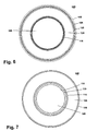
- variable taper portion 126 be selected such that the width (Dimension A, Fig. 5 ) of the lip along the upper edge be the same dimension as that found on similar sized foam-only cups as this will permit current lids for the foam-only cups to be used on the paper-wrapped foam cups 100.
- the foot 114 of the cup 100 is potentially subject to the same shrinkage-induced curling as the lip 110. If the foot 114 were to curl a sufficient amount that the foot 114 did not rest on the shoulder 116 of another cup when stacked, it would have a devastating impact on the stacking and separation of the cups. However, the additional strength and material mass provided by the fillet 118 sufficiently controls any curling of the foot 114.
- the fillet 118 is further beneficial in that it provides additional structure support for the foot 114 against pressure applied to the foot 114 during the wrapping process. Unlike the sidewalls of the cup which are internally supported by a mandrel during wrapping, the interior of the foot 114 is unsupported. The ability to apply pressure to the foot 114 without fear of the foot 114 collapsing enhances the adhesion of the paper wrapper 104 to the foot 114, which reduces the likelihood that the paper will buckle or wrinkle at the foot 114.
- the dimensions for the cup relate to a 16 oz cup made from expanded polystyrene foam having a density of approximately 52,54 kg/m 3 (3.28 lb/ft 3 ) and a sidewall thickness along the constant taper portion 124 of approximately 2,08 mm (0.082 inches).
- these cup parameters can vary with cup size.
- the sidewall thickness often varies with the volume of the cup. The greater the volume, the greater the wall thickness to help structurally support the additional beverage volume. All else being equal, the sidewall thickness of a paper wrapped foam cup is less than a foam-only cup because of the extra strength provided by the paper.
- the paper wrapper 104 has features that also contribute to a commercially successful paper-wrapped cup.
- the paper wrapper 104 extends substantially from the lip 110 to the bottom of the foot 114.
- the paper wrapper 104 preferably stops approximately 0,762 mm (0.030 inches) from the lip 110 and 0,762 mm (0.030 inches) from the bottom of the foot 114. Even with the 0,762 mm (0.030 inch) gap between the paper and the lip 100 and foot 114, when a lid is placed on the cup 100, the cup 100 has the appearance of a paper-only cup since almost all of the foam is hidden from the consumer.
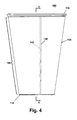
- the paper wrapper 104 completely circumscribes the cup 110 and has opposing ends 140 and 142 ( Fig. 4 ), with one of the ends (illustrated as end 140) butting to overlapping the other end.
- the overlap is beneficial in that it ensures that no portion of the foam cup 102 is visible, which is aesthetically superior for most consumers, who perceive it as a higher quality cup. It is preferred that the overlap does not exceed 1,016 mm (0.040 inches). Overlaps of less than this amount have shown the least tendency to wrinkle.
- the overlap preferably ranges from abutting to less than approximately 1,016 mm (40 mils).
- the combination of paper thickness and the extent of overlap results in the consumer not being able to feel the overlapped portion, which also enhances the aesthetics of the cup 100, adding to the commercial success of the cup 100.
- the overlapping portion of the paper wrapper 104 is not bonded to the underlying portion of the paper wrapper 104 to prevent the formation of any wrinkles in the paper wrapper 104 along the overlapping portion in response to the shrinkage of the cup 102. It is also preferred that the overlap is less than 1,016 mm (0.040 inches) to reduce the possibility of wrinkling.
- the paper can be any suitable type of paper. For example, it can be coated or uncoated. It can be fiber-based or polymer-based. It can be a single layer or multiple layers.
- the paper can have suitable bonding materials incorporated into the coating as does the Capri Gloss made by Stora Enso.
- a specially selected bonding material such as an adhesive, can be added to the paper as part of wrapping of the paper to the cup.
- the specific adhesive is not germane to the invention.
- Fig. 10 illustrates a schematic of an assembly machine 200 suitable for assembling the paper wrapped cup 100.
- the assembly machine 200 comprises a paper roll 202 comprising a web of paper 204 on which are printed multiple paper wrappers 104.
- the web 204 is fed through a punch assembly 206 that punches the paper wrappers 104 from the web 204, with the skeleton of the punched web being fed to a take up roll 205.
- the punched paper wrappers 104 are then picked up by a reciprocating arm 208 and placed on a rotation platen 210, which carries the paper wrappers 104 to a rotating mandrel assembly 212 where the paper wrappers 104 are wrapped about a foam cup.
- the mandrel assembly 212 is fed pre-made foam cups from an escapement 216.
- a cup out-feeder 218 receives and stacks the wrapped cups 100.
- the punch assembly 206 is preferably a traditional punch and die.
- the reciprocating arm 208 comprises a pick up 222, which is conveniently shaped to correspond to the shape of the paper wrapper 104.
- the pick up 222 also comprises several air passages through which pressurized air or a vacuum can be applied to the paper wrapper 104 to aid in the picking up and releasing of a paper wrapper 104.
- the rotating platen 210 comprises multiple spaced carriers 226, each one sized to support a paper wrapper 104.
- the spacing between the carriers 226 is great enough to permit the passage of the mandrel assembly 212.
- each of the spaced carriers has a series of air passages 228 such that either a vacuum or pressurized air can be applied to the paper wrapper 104 to aid in holding the paper wrapper 104 to the carrier 226 or removing the paper wrapper 104 from the carrier.
- the mandrel assembly 212 comprises a rotating hub 230 from which extend multiple spokes 232.
- a mandrel 214 is rotatably mounted to each of the spokes such that the mandrel 214 can rotate about the longitudinal axis of the corresponding spoke 232.
- Each mandrel 214 comprises multiple air passages 236 through which either pressurized air or a vacuum can be applied to a foam cup 102 carried by the mandrel to aid in the holding or releasing of the cup to and from the mandrel 214.
- External pressurized air nozzles 238 aid in the removal of the wrapped cups 100 by providing a blast of pressurized air to blow the cup 100 off of the mandrel 214.
- the escapement 216 is well known in the industry and comprises a chute 240 in which is received a stack of foam cups 102. Any one of several well known cup feed mechanism can be used to release one cup 102 at a time onto a mandrel 214 positioned beneath the chute 240.
- Known cup feed mechanisms include rotating screws and cams. The type of feed mechanism is not germane to the invention.
- the out-feeder 218 comprises a cup receiving chute 250 partially defined by a series of rollers 252 and guide plates 254.
- the rollers 252 are preferably brush rollers, with at least the first upper and lower rollers being drive rollers.
- the drive rollers can be rotated to propel a cup received between the drive rollers further into the chute.
- a controller is provided to synchronize the movement of the various elements of the assembly machine 200, including the actuation of the various air pressure and vacuum supplies.
- a suitable controller would be a programmable logic controller.
- the web 204 is advanced from the paper roll 202 through the punch assembly 206 and onto the take up roll 205. As the web 204 passes through the punch assembly 206, the individual paper wrappers 104 are punched from the web 204.
- the pick up 222 of the reciprocating arm 208 is lowered onto the punched paper wrapper 104 and the vacuum is applied to the pick up 222 to hold the paper wrapper 104 to the pick up 222.
- the reciprocating arm 208 then moves such that the pick up 222 is positioned above a carrier 226.
- the reciprocating arm 208 is then lowered to bring the pick up 222 into contact with the carrier 226.
- the vacuum to the pick up 222 is stopped and vacuum is then applied to the carrier 226 to transfer the paper wrapper 104 to the carrier 226.
- the paper wrapper 104 is then heated while it is on the carrier 226.
- the heating can be accomplished by providing an external heater that radiates heat onto the paper wrapper 104.
- the carriers 226 are directly heated, such as by a resistive heating element.
- the paper wrapper 104 is heated as the carrier 226 is rotatably indexed to the mandrel assembly 212.
- the temperature of the carrier plate is between 190,6° and 204,4°C (375° and 400° F) and the paper wrapper 104 sits on the carrier 226 for between 8 to 15 seconds. Testing has shown that this temperature and time combination is sufficient to heat the paper wrapper 104 such that the bonding materials in the preferred paper are suitable for bonding to the foam cup 102.
- the preferred temperature is 204,4°C (400 ° F) and the time to wrap the paper wrapper is 1-3 seconds. In some tests, plate temperature of 208,9°C (440° F) were needed to obtain the desired degree of adhesion.
- the carrier 226 is ultimately brought into position with one of the mandrels 214 on which a cup 102 is being carried.
- the platen 210 and mandrel assembly 212 are indexed such that the cup-carrying mandrel 214 is brought into contact with the leading edge of the carrier 226.
- the cup-carrying mandrel 214 remains in this position, the platen 210 continues to rotate beneath the mandrel 214. Since the mandrel 214 is free to rotate relative to the spoke 232, the rotation of the platen 210 effectively rolls the mandrel 214 and the cup 102 it is carrying along the paper wrapper 104. In this manner the paper wrapper 104 is wrapped about the cup 102.
- the mandrel 214 is positioned above the space between the carriers 226.
- the mandrel assembly 212 then rotates the next mandrel into position to wrap another cup.
- the wrapped cup 100 is eventually rotated into alignment with the chute 250 of the out-feeder 218.
- the vacuum to the mandrel 214 is replaced by pressurized air and the external air nozzles 238 hit the cup 100 with a blast of pressurized air.
- the pressurized air from the mandrel and the air nozzles 238 force the cup 100 off of the mandrel 214 and into the chute 250.
- the drive rollers 252 are continuously activated to propel the expelled cup 100 further down the chute 250 and stack the cup 100 within any waiting cups.
- the previously emptied mandrel is rotated beneath the escapement 216. In this position, a vacuum is applied to the mandrel and the lowermost cup 102 of the stack is moved onto the mandrel 214 by the escapement 216.
- the process is repeated until the paper wrapping is completed.
- the out-feeder 218 can be coupled to a traditional packaging assembly line. In such situation, the cups 100 would be ejected from the chute 250 when a predetermined number were stacked therein. The ejected stack of cups 100 would then be automatically bagged and put into a suitable container for shipping. Preferably, the out-feeder 218 would stack the cups within a protective sleeve prior to ejection.
- the escapement 216 can be directly fed cups 102 from a traditional cup manufacturing line.
- the benefit of this configuration is that it is not necessary to inventory the cups prior to wrapping, which reduces space and capital requirements.
- the invention is ideally suited for immediately wrapping freshly made foam cups.
- Freshly made cups are subject to more curling than cups that have aged prior to wrapping. This is because the cups immediately begin shrinking, subject to some temporary post-molding expansion, after they are made. Cups that are permitted to age prior to wrapping will have less curling since the cup is permitted to shrink in all dimensions. While the wrapping of sufficiently aged cups is one way to minimize curling, given the large production volumes used in contemporary cup molding facilities, it is not cost effective to provided the needed capital and storage for the aged cups.
Landscapes
- Engineering & Computer Science (AREA)
- Mechanical Engineering (AREA)
- Ceramic Engineering (AREA)
- Packages (AREA)
- Making Paper Articles (AREA)
- Stackable Containers (AREA)
- Basic Packing Technique (AREA)
- Containers Having Bodies Formed In One Piece (AREA)
- Details Of Rigid Or Semi-Rigid Containers (AREA)
Claims (16)
- Umwickelter Schaumstoffbecher (100) umfassend:einen Schaumstoff-Formbecher (102), der eine Bodenwand (108) und eine sich von der Bodenwand (108) weg erstreckende Umfangswand (106) aufweist, wobei die Bodenwand eine Oberseite und eine Unterseite besitzt, die Umfangswand (106) eine Innenfläche (122) und eine Außenfläche (120) umfasst, die Oberseite und die Innenfläche (122) einen Getränkehohlraum (112) begrenzen und die Umfangswand (106) in einer Oberkante (110) endet, welche eine Öffnung des Getränkehohlraums (112) begrenzt,eine Hülle (104), die um die Außenfläche (120) des Bechers (102) gewickelt und daran angebondet ist, wobei die Hülle (104) einander entgegengesetzte Enden (140, 142) aufweist, welche durch eine obere Kante und eine untere Kante miteinander verbunden sind, wobei die obere Kante nahe der Oberkante (110) des Bechers (102) liegt; dadurch gekennzeichnet, dassdie Umfangswand einen ersten Abschnitt (124) mit einer ersten Konizität und einen zweiten Abschnitt (126) mit einer zweiten Konizität aufweist, wobei sich der zweite Abschnitt (126) von dem ersten Abschnitt (124) weg zur Oberkante (110) erstreckt, die obere Kante der Hülle (104) auf dem zweiten Abschnitt der Umfangswand (106) liegt und die zweite Konizität größer ist als die erste Konizität.
- Umwickelter Schaumstoffbecher nach Anspruch 1, wobei die Oberkante eine Lippe (110) zur Halterung eines Deckels bildet.
- Umwickelter Schaumstoffbecher nach Anspruch 1, wobei der zweite Abschnitt (126) eine geringere Dicke aufweist als der erste Abschnitt (124).
- Umwickelter Schaumstoffbecher nach Anspruch 3, wobei der zweite Abschnitt (126) eine sich in eine Richtung zur oberen Kante (110) der Umfangswand (106) hin kontinuierlich verringernde Dicke aufweist.
- Umwickelter Schaumstoffbecher nach Anspruch 1, wobei die zweite Konizität variabel ist.
- Umwickelter Schaumstoffbecher nach Anspruch 5, wobei die erste Konizität konstant ist.
- Umwickelter Schaumstoffbecher nach Anspruch 6, wobei sich die erste Konizität entlang der gesamten Länge des ersten Abschnitts (124) der Umfangswand (106) erstreckt.
- Umwickelter Schaumstoffbecher nach Anspruch 1, wobei der Becher zusätzlich einen Absatz (116) zur Abstützung eines gleichartigen umwickelten Schaumstoffbechers (100) aufweist, wenn dieser sich in einer ineinandergesteckten Anordnung mit dem umwickelten Schaumstoffbecher (100) befindet, wobei der Absatz (116) entlang der Innenfläche (122) der Umfangswand (106) derart angeordnet ist, dass zwischen den Umfangswänden (106) der ineinandergesteckten Becher (100) ein Luftspalt (130) entsteht.
- Umwickelter Schaumstoffbecher nach Anspruch 8, wobei die zweite Konizität derart gestaltet ist, dass sich die Oberkante (110) des Schaumstoffbechers (102) beim Schrumpfen des umwickelten Schaumstoffbechers (100) nicht über den Luftspalt (130) hinaus in den Hohlraum (112) hineinerstreckt.
- Umwickelter Schaumstoffbecher nach Anspruch 1, wobei die Abschnitte der einander entgegengesetzten Enden (140, 142) in einer einander überlappenden Beziehung zueinander stehen.
- Umwickelter Schaumstoffbecher nach Anspruch 10, wobei die Abschnitte der einander entgegengesetzten Enden (140, 142) nicht zusammengebondet sind.
- Umwickelter Schaumstoffbecher nach Anspruch 11, wobei die Oberkante der Umfangswand (106) eine Lippe (110) bildet und die obere Kante der Hülle (104) an diese Lippe (110) angrenzt.
- Umwickelter Schaumstoffbecher nach Anspruch 1 oder 12, wobei der Becher (100) zusätzlich einen Sockel (114) umfasst, der sich von der Bodenwand (108) aus nach unten erstreckt, und die Unterkante der Hülle (104) über einem Abschnitt des Sockels (114) liegt.
- Umwickelter Schaumstoffbecher nach Anspruch 13, wobei der Becher zusätzlich eine Kehle (118) umfasst, die sich zwischen dem Sockel (114) und der Unterseite der Bodenwand (108) erstreckt.
- Umwickelter Schaumstoffbecher nach Anspruch 1 oder 14, wobei die Hülle (104) aus Papier besteht.
- Umwickelter Schaumstoffbecher nach Anspruch 15, wobei das Papier beschichtet ist und die Beschichtung geeignete Bonding-Materialien zum Befestigen des Papiers am Schaumstoffbecher (102) umfasst.
Priority Applications (1)
| Application Number | Priority Date | Filing Date | Title |
|---|---|---|---|
| EP07119352A EP1892189B1 (de) | 2004-04-08 | 2005-04-07 | Wickelvorrichtung für Schaumstoffbecher |
Applications Claiming Priority (2)
| Application Number | Priority Date | Filing Date | Title |
|---|---|---|---|
| US52135904P | 2004-04-08 | 2004-04-08 | |
| PCT/US2005/011809 WO2005100167A1 (en) | 2004-04-08 | 2005-04-07 | Paper wrapped foam cup and method of assembly |
Related Child Applications (1)
| Application Number | Title | Priority Date | Filing Date |
|---|---|---|---|
| EP07119352A Division EP1892189B1 (de) | 2004-04-08 | 2005-04-07 | Wickelvorrichtung für Schaumstoffbecher |
Publications (2)
| Publication Number | Publication Date |
|---|---|
| EP1742845A1 EP1742845A1 (de) | 2007-01-17 |
| EP1742845B1 true EP1742845B1 (de) | 2008-12-24 |
Family
ID=34964699
Family Applications (2)
| Application Number | Title | Priority Date | Filing Date |
|---|---|---|---|
| EP05732195A Expired - Lifetime EP1742845B1 (de) | 2004-04-08 | 2005-04-07 | Papierumwickelter schaumstoffbecher |
| EP07119352A Expired - Lifetime EP1892189B1 (de) | 2004-04-08 | 2005-04-07 | Wickelvorrichtung für Schaumstoffbecher |
Family Applications After (1)
| Application Number | Title | Priority Date | Filing Date |
|---|---|---|---|
| EP07119352A Expired - Lifetime EP1892189B1 (de) | 2004-04-08 | 2005-04-07 | Wickelvorrichtung für Schaumstoffbecher |
Country Status (13)
| Country | Link |
|---|---|
| US (3) | US9527620B2 (de) |
| EP (2) | EP1742845B1 (de) |
| JP (1) | JP2007532418A (de) |
| CN (2) | CN101327648B (de) |
| AR (3) | AR053746A1 (de) |
| AT (2) | ATE418496T1 (de) |
| AU (1) | AU2005233138B2 (de) |
| BR (1) | BRPI0508838B1 (de) |
| CA (2) | CA2562150C (de) |
| DE (1) | DE602005011953D1 (de) |
| MX (1) | MXPA06011562A (de) |
| NZ (2) | NZ549555A (de) |
| WO (1) | WO2005100167A1 (de) |
Families Citing this family (42)
| Publication number | Priority date | Publication date | Assignee | Title |
|---|---|---|---|---|
| DE60102661T2 (de) | 2001-01-30 | 2004-08-19 | Seda S.P.A. | Pappbehälter für Getränke und Verfahren hierfür |
| ATE418496T1 (de) * | 2004-04-08 | 2009-01-15 | Dart Container | Papierumwickelter schaumstoffbecher |
| AU2005235615B2 (en) | 2004-04-22 | 2010-07-22 | Dixie Consumer Products Llc | Insulating cup wrapper and insulated container formed with wrapper |
| BRPI0601188B1 (pt) | 2005-04-15 | 2018-06-26 | Seda S.P.A. | Recipiente isolado; método de fabricar o mesmo e aparelho para a fabricação |
| US7536767B2 (en) | 2005-05-27 | 2009-05-26 | Prairie Packaging, Inc. | Method of manufacturing a reinforced plastic foam cup |
| US7552841B2 (en) | 2005-05-27 | 2009-06-30 | Prairie Packaging, Inc. | Reinforced plastic foam cup, method of and apparatus for manufacturing same |
| US7694843B2 (en) | 2005-05-27 | 2010-04-13 | Prairie Packaging, Inc. | Reinforced plastic foam cup, method of and apparatus for manufacturing same |
| US7704347B2 (en) | 2005-05-27 | 2010-04-27 | Prairie Packaging, Inc. | Reinforced plastic foam cup, method of and apparatus for manufacturing same |
| US7814647B2 (en) | 2005-05-27 | 2010-10-19 | Prairie Packaging, Inc. | Reinforced plastic foam cup, method of and apparatus for manufacturing same |
| US7818866B2 (en) | 2005-05-27 | 2010-10-26 | Prairie Packaging, Inc. | Method of reinforcing a plastic foam cup |
| DE202005014177U1 (de) | 2005-09-08 | 2005-11-17 | Seda S.P.A., Arzano | Doppelwandiger Becher |
| DE602005005493T3 (de) * | 2005-11-11 | 2014-04-24 | Seda S.P.A. | Isolierbecher |
| EP1785265A1 (de) | 2005-11-14 | 2007-05-16 | SEDA S.p.A. | Vorrichtung zur Ausformung eine Stapelwulst an einer Behälterwand und Behälter mit derselben |
| US7828199B2 (en) * | 2006-07-27 | 2010-11-09 | Huhtamaki, Inc. | Multi-layer heat insulating container |
| DE202006018406U1 (de) | 2006-12-05 | 2008-04-10 | Seda S.P.A. | Verpackung |
| US20080197047A1 (en) * | 2007-02-15 | 2008-08-21 | Kidkupz Llc | Pedeatric medicine dosage cup, tray and fabrication method |
| US8389080B2 (en) * | 2008-07-16 | 2013-03-05 | Ws Packaging Group, Inc. | Label-wrapped foam cups with patterned adhesive |
| DE102008064505B4 (de) * | 2008-12-22 | 2017-02-02 | Michael Hörauf Maschinenfabrik GmbH & Co. KG | Verfahren zum Herstellen von geklebten Hülsen |
| AT508081B1 (de) * | 2009-04-01 | 2012-04-15 | Rundpack Ag | Kombi-verpackungsbehälter sowie verfahren zu dessen herstellung |
| US8828170B2 (en) | 2010-03-04 | 2014-09-09 | Pactiv LLC | Apparatus and method for manufacturing reinforced containers |
| JP2012024962A (ja) * | 2010-07-21 | 2012-02-09 | Nippon Dekishii:Kk | テーパー形状紙容器の成形機 |
| JP5535804B2 (ja) * | 2010-07-21 | 2014-07-02 | 株式会社日本デキシー | テーパー形状紙容器の成形機 |
| KR101367018B1 (ko) * | 2010-09-27 | 2014-02-24 | 변동환 | 접이식 종이컵의 옆지 성형 방법과 접이식 종이컵 |
| US20120264581A1 (en) * | 2011-04-12 | 2012-10-18 | Vladislav Babinsky | System and Method for Forming a Multiple Wall Container |
| USD682088S1 (en) | 2011-08-04 | 2013-05-14 | Grupo Convermex, S.A. De C.V. | Container |
| DE102012220112A1 (de) * | 2012-11-05 | 2014-05-22 | Michael Hörauf Maschinenfabrik GmbH & Co. KG | Isolierbecher und Verfahren zum Herstellen eines Isolierbechers |
| WO2015024199A1 (zh) * | 2013-08-20 | 2015-02-26 | Chang Ching-Wen | 纸容器发泡装置 |
| CN104416708A (zh) * | 2013-08-20 | 2015-03-18 | 张静文 | 纸容器发泡装置 |
| CA2898810C (en) * | 2014-08-01 | 2017-01-03 | Nicolas Bouveret | Anti-depression plastic container |
| CN105345980A (zh) * | 2014-08-19 | 2016-02-24 | 张静文 | 纸容器发泡装置 |
| US9580288B2 (en) * | 2014-09-05 | 2017-02-28 | Dianna Ploss | Water dispenser cover |
| MX2019001951A (es) * | 2016-08-16 | 2019-05-15 | Grupo Convermex S A De C V | Sistemas y metodos para formar y etiquetar contenedores. |
| US11067368B1 (en) | 2017-01-05 | 2021-07-20 | Government Of The United States, As Represented By The Secretary Of The Army | Composite enclosure for explosive reactive armor and methods of manufacturing the same |
| US10377517B2 (en) | 2017-03-16 | 2019-08-13 | Dart Container Corporation | Method and apparatus for assembling a double-walled container |
| CN107416254A (zh) * | 2017-07-25 | 2017-12-01 | 佛山市正略信息科技有限公司 | 一种led灯管气泡膜缠绕装置 |
| GB2565118B (en) * | 2017-08-02 | 2020-09-16 | Bockatech Ltd | Hollow plastic article |
| CA3053066C (en) * | 2018-08-30 | 2023-01-10 | Dart Container Corporation | Method and apparatus for assembling a double-walled container |
| TWI739141B (zh) * | 2019-08-09 | 2021-09-11 | 晉豪環保科技股份有限公司 | 紙容器發泡裝置 |
| USD936424S1 (en) | 2020-02-10 | 2021-11-23 | David Lee Thomas, Jr. | Double rim cup |
| US20210292079A1 (en) * | 2020-03-17 | 2021-09-23 | Ecopax, LLC | Disposable insulated drinking vessel and method of making the same |
| JP7457602B2 (ja) * | 2020-08-18 | 2024-03-28 | Kisco株式会社 | ストロー一体型飲料容器 |
| TR2022005633A1 (tr) * | 2022-04-08 | 2023-10-23 | Mondi Kale Nobel Ambalaj Sanayi Ve Ticaret Anonim Sirketi | Di̇key beslemeli̇ kornet külah ambalaji üreti̇m maki̇nesi̇ |
Family Cites Families (48)
| Publication number | Priority date | Publication date | Assignee | Title |
|---|---|---|---|---|
| US2917217A (en) | 1956-04-30 | 1959-12-15 | St Regis Paper Co | Foamed polystyrene article |
| US3333515A (en) | 1964-05-08 | 1967-08-01 | Continental Can Co | Container forming |
| JPS4827443Y1 (de) * | 1970-08-05 | 1973-08-13 | ||
| US3696987A (en) * | 1971-02-26 | 1972-10-10 | Dart Ind Inc | Coated cup and method of manufacture |
| US3754699A (en) | 1971-07-13 | 1973-08-28 | Dart Ind Inc | Reinforced large polystyrene container |
| US3759437A (en) | 1971-07-14 | 1973-09-18 | Owens Illinois Inc | Composite container |
| US4197948A (en) * | 1971-12-23 | 1980-04-15 | Owens-Illinois, Inc. | Nestable foam cup |
| CA976791A (en) * | 1972-02-14 | 1975-10-28 | Ralph G. Amberg | Method and apparatus for assembling composite containers |
| JPS5148587B2 (de) * | 1972-03-09 | 1976-12-21 | ||
| US3988521A (en) | 1972-07-28 | 1976-10-26 | Owens-Illinois, Inc. | Laminated structures and methods and compositions for producing same |
| US4007670A (en) | 1974-02-28 | 1977-02-15 | St. Regis Paper Company | Insulated container |
| JPS5442803Y2 (de) * | 1975-03-26 | 1979-12-12 | ||
| US4016327A (en) | 1975-05-02 | 1977-04-05 | Owens-Illinois, Inc. | Laminated structures and methods and compositions for producing same |
| JPS5230301U (de) * | 1975-08-21 | 1977-03-03 | ||
| JPS5845345B2 (ja) * | 1976-06-04 | 1983-10-08 | 大日本印刷株式会社 | ブロッキングを防止した断熱カップの製法 |
| DE2700230C2 (de) | 1977-01-05 | 1984-08-23 | Maschinenfabrik Rissen Gmbh, 2000 Hamburg | Becherförmiger Behälter |
| US4193494A (en) * | 1978-08-28 | 1980-03-18 | Compact Industries, Inc. | Cup and package of cups |
| US4273816A (en) * | 1979-07-30 | 1981-06-16 | Custom Made Packaging Inc. | Foam based structure |
| US4288026A (en) * | 1979-09-06 | 1981-09-08 | American Can Company | Container structure |
| US4332635A (en) * | 1980-07-03 | 1982-06-01 | American Can Company | Cup labeling method and apparatus |
| US4420081A (en) * | 1981-06-22 | 1983-12-13 | Dart Container Corporation | Step-wall nestable cup |
| JPS5829928U (ja) * | 1981-08-20 | 1983-02-26 | 積水化成品工業株式会社 | 容器 |
| CA1225048A (en) * | 1985-04-25 | 1987-08-04 | Roboserve Limited | Nestable, lockable foamed thermoplastic container and cup |
| US4832783A (en) * | 1985-07-01 | 1989-05-23 | Dennison Manufacturing Company | Apparatus for rotational decoration of articles |
| JPS6397613U (de) * | 1986-12-17 | 1988-06-24 | ||
| JPH0348016Y2 (de) * | 1986-12-24 | 1991-10-14 | ||
| JPH0340731Y2 (de) * | 1987-03-17 | 1991-08-27 | ||
| US4819406A (en) * | 1987-09-25 | 1989-04-11 | Sanford Redmond Inc. | Compact form-fill-seal machine for automatic production of sealed packages |
| JPH02129040U (de) * | 1989-03-31 | 1990-10-24 | ||
| JP3383698B2 (ja) * | 1993-11-26 | 2003-03-04 | 三陽パックス株式会社 | 合成樹脂製カップ |
| DE4409952C1 (de) * | 1994-03-23 | 1995-02-02 | Hatto Hartnagel | Etikettiervorrichtung |
| US5547124A (en) * | 1995-07-18 | 1996-08-20 | Michael Hoerauf Maschinenfabrik Gmbh & Co. Kg | Heat insulating container |
| EP0812668A4 (de) * | 1995-12-28 | 2001-10-31 | Sekisui Plastics | Verfahren und vorrichtung zum herstellen von geschräumten harzbehaltern mit etiketten |
| US6224954B1 (en) | 1997-03-26 | 2001-05-01 | Fort James Corporation | Insulating stock material and containers and methods of making the same |
| CN100396478C (zh) * | 1997-08-28 | 2008-06-25 | 大日本印刷株式会社 | 肋加工装置 |
| US5911904A (en) | 1997-12-16 | 1999-06-15 | International Paper Company | Foamable insulating barrier coating |
| US6257485B1 (en) | 1998-11-30 | 2001-07-10 | Insulair, Inc. | Insulated cup and method of manufacture |
| CA2315866A1 (en) | 1999-08-23 | 2001-02-23 | Patrick L. Maynard (Deceased) | Method and apparatus for making heat-insulative foamed layer containers and making a web of heat-insulative foamed layer material |
| US20020172784A1 (en) | 2001-04-05 | 2002-11-21 | Appleton Papers Inc. | Beverage and food containers, outwardly directed foam |
| US6811843B2 (en) | 2001-04-05 | 2004-11-02 | Appleton Papers Inc. | Insulated beverage or food container |
| US7074466B2 (en) | 2001-04-05 | 2006-07-11 | Appleton Papers Inc. | Beverage and food containers, inwardly directed foam |
| US7811644B2 (en) | 2001-04-05 | 2010-10-12 | Appleton Papers Inc. | Insulated beverage or food container |
| JP2004099079A (ja) * | 2002-09-06 | 2004-04-02 | Nippon Paper-Pak Co Ltd | 複層容器 |
| US6814253B2 (en) * | 2002-10-15 | 2004-11-09 | Double Team Inc. | Insulating sleeve for grasping container and manufacturing method |
| US6960316B2 (en) * | 2002-10-30 | 2005-11-01 | Sorensen Research And Development Trust | Injection-molded plastic container or closure with turned-under rim and method of injection-molding same |
| US7546932B2 (en) * | 2003-10-01 | 2009-06-16 | Solo Cup Operating Corporation | Ergonomic disposable cup having improved structural integrity |
| ATE418496T1 (de) * | 2004-04-08 | 2009-01-15 | Dart Container | Papierumwickelter schaumstoffbecher |
| JP5829928B2 (ja) | 2012-01-24 | 2015-12-09 | 蛇の目ミシン工業株式会社 | 自動糸切り装置を備えたミシン |
-
2005
- 2005-04-07 AT AT05732195T patent/ATE418496T1/de not_active IP Right Cessation
- 2005-04-07 WO PCT/US2005/011809 patent/WO2005100167A1/en not_active Ceased
- 2005-04-07 AT AT07119352T patent/ATE512887T1/de not_active IP Right Cessation
- 2005-04-07 CA CA2562150A patent/CA2562150C/en not_active Expired - Fee Related
- 2005-04-07 CN CN2008101360884A patent/CN101327648B/zh not_active Expired - Fee Related
- 2005-04-07 AR ARP050101377A patent/AR053746A1/es not_active Application Discontinuation
- 2005-04-07 MX MXPA06011562A patent/MXPA06011562A/es active IP Right Grant
- 2005-04-07 NZ NZ549555A patent/NZ549555A/en not_active IP Right Cessation
- 2005-04-07 EP EP05732195A patent/EP1742845B1/de not_active Expired - Lifetime
- 2005-04-07 AU AU2005233138A patent/AU2005233138B2/en not_active Ceased
- 2005-04-07 BR BRPI0508838-0A patent/BRPI0508838B1/pt not_active IP Right Cessation
- 2005-04-07 US US10/907,597 patent/US9527620B2/en active Active
- 2005-04-07 DE DE602005011953T patent/DE602005011953D1/de not_active Expired - Fee Related
- 2005-04-07 CN CN2005800080772A patent/CN1930041B/zh not_active Expired - Fee Related
- 2005-04-07 NZ NZ580847A patent/NZ580847A/en not_active IP Right Cessation
- 2005-04-07 CA CA2750996A patent/CA2750996C/en not_active Expired - Fee Related
- 2005-04-07 JP JP2007507504A patent/JP2007532418A/ja active Pending
- 2005-04-07 EP EP07119352A patent/EP1892189B1/de not_active Expired - Lifetime
-
2007
- 2007-12-28 US US11/965,815 patent/US7549273B2/en not_active Expired - Lifetime
-
2009
- 2009-05-14 US US12/465,695 patent/US7856793B2/en not_active Expired - Fee Related
-
2011
- 2011-09-27 AR ARP110103537A patent/AR083132A2/es not_active Application Discontinuation
- 2011-09-27 AR ARP110103538A patent/AR083133A2/es not_active Application Discontinuation
Also Published As
Similar Documents
| Publication | Publication Date | Title |
|---|---|---|
| EP1742845B1 (de) | Papierumwickelter schaumstoffbecher | |
| US10773840B2 (en) | Method and apparatus for assembling a double-walled container | |
| US20050040218A1 (en) | Unitary double walled container and method for making | |
| US3337109A (en) | Container holders | |
| EP2658786B1 (de) | Verbesserter pappbecher | |
| MXPA06012135A (es) | Envoltura para copa aislante y contenedor aislado formado con envoltura. | |
| JPH05330552A (ja) | 熱可塑性カップ | |
| US20180263391A1 (en) | Method of assembling a double-walled container | |
| AU620236B2 (en) | Method and apparatus for forming a fabricated thermoplastic container | |
| JP3075141B2 (ja) | 断熱カップ | |
| HK1124808B (en) | Apparatus for forming wrapped foam cup | |
| CA3053066C (en) | Method and apparatus for assembling a double-walled container | |
| JPS63500164A (ja) | コップのリム及び成形方法 | |
| EP4494859A1 (de) | Verfahren zur herstellung eines vielseitigen papierdeckels für getränkebehälter und papierdeckel | |
| JP3671463B2 (ja) | 断熱カップ | |
| US20120292218A1 (en) | Shrink sleeve labeled eps foam container | |
| JPH0958657A (ja) | 断熱カップ |
Legal Events
| Date | Code | Title | Description |
|---|---|---|---|
| PUAI | Public reference made under article 153(3) epc to a published international application that has entered the european phase |
Free format text: ORIGINAL CODE: 0009012 |
|
| 17P | Request for examination filed |
Effective date: 20061020 |
|
| AK | Designated contracting states |
Kind code of ref document: A1 Designated state(s): AT BE BG CH CY CZ DE DK EE ES FI FR GB GR HU IE IS IT LI LT LU MC NL PL PT RO SE SI SK TR |
|
| 17Q | First examination report despatched |
Effective date: 20070205 |
|
| DAX | Request for extension of the european patent (deleted) | ||
| RTI1 | Title (correction) |
Free format text: PAPER WRAPPED FOAM CUP |
|
| GRAP | Despatch of communication of intention to grant a patent |
Free format text: ORIGINAL CODE: EPIDOSNIGR1 |
|
| GRAS | Grant fee paid |
Free format text: ORIGINAL CODE: EPIDOSNIGR3 |
|
| GRAA | (expected) grant |
Free format text: ORIGINAL CODE: 0009210 |
|
| AK | Designated contracting states |
Kind code of ref document: B1 Designated state(s): AT BE BG CH CY CZ DE DK EE ES FI FR GB GR HU IE IS IT LI LT LU MC NL PL PT RO SE SI SK TR |
|
| REG | Reference to a national code |
Ref country code: GB Ref legal event code: FG4D |
|
| REG | Reference to a national code |
Ref country code: CH Ref legal event code: EP |
|
| REG | Reference to a national code |
Ref country code: IE Ref legal event code: FG4D |
|
| REF | Corresponds to: |
Ref document number: 602005011953 Country of ref document: DE Date of ref document: 20090205 Kind code of ref document: P |
|
| PG25 | Lapsed in a contracting state [announced via postgrant information from national office to epo] |
Ref country code: LT Free format text: LAPSE BECAUSE OF FAILURE TO SUBMIT A TRANSLATION OF THE DESCRIPTION OR TO PAY THE FEE WITHIN THE PRESCRIBED TIME-LIMIT Effective date: 20081224 |
|
| PG25 | Lapsed in a contracting state [announced via postgrant information from national office to epo] |
Ref country code: NL Free format text: LAPSE BECAUSE OF FAILURE TO SUBMIT A TRANSLATION OF THE DESCRIPTION OR TO PAY THE FEE WITHIN THE PRESCRIBED TIME-LIMIT Effective date: 20081224 Ref country code: FI Free format text: LAPSE BECAUSE OF FAILURE TO SUBMIT A TRANSLATION OF THE DESCRIPTION OR TO PAY THE FEE WITHIN THE PRESCRIBED TIME-LIMIT Effective date: 20081224 Ref country code: SI Free format text: LAPSE BECAUSE OF FAILURE TO SUBMIT A TRANSLATION OF THE DESCRIPTION OR TO PAY THE FEE WITHIN THE PRESCRIBED TIME-LIMIT Effective date: 20081224 Ref country code: PL Free format text: LAPSE BECAUSE OF FAILURE TO SUBMIT A TRANSLATION OF THE DESCRIPTION OR TO PAY THE FEE WITHIN THE PRESCRIBED TIME-LIMIT Effective date: 20081224 |
|
| NLV1 | Nl: lapsed or annulled due to failure to fulfill the requirements of art. 29p and 29m of the patents act | ||
| PG25 | Lapsed in a contracting state [announced via postgrant information from national office to epo] |
Ref country code: RO Free format text: LAPSE BECAUSE OF FAILURE TO SUBMIT A TRANSLATION OF THE DESCRIPTION OR TO PAY THE FEE WITHIN THE PRESCRIBED TIME-LIMIT Effective date: 20081224 Ref country code: BE Free format text: LAPSE BECAUSE OF FAILURE TO SUBMIT A TRANSLATION OF THE DESCRIPTION OR TO PAY THE FEE WITHIN THE PRESCRIBED TIME-LIMIT Effective date: 20081224 Ref country code: ES Free format text: LAPSE BECAUSE OF FAILURE TO SUBMIT A TRANSLATION OF THE DESCRIPTION OR TO PAY THE FEE WITHIN THE PRESCRIBED TIME-LIMIT Effective date: 20090404 Ref country code: EE Free format text: LAPSE BECAUSE OF FAILURE TO SUBMIT A TRANSLATION OF THE DESCRIPTION OR TO PAY THE FEE WITHIN THE PRESCRIBED TIME-LIMIT Effective date: 20081224 Ref country code: BG Free format text: LAPSE BECAUSE OF FAILURE TO SUBMIT A TRANSLATION OF THE DESCRIPTION OR TO PAY THE FEE WITHIN THE PRESCRIBED TIME-LIMIT Effective date: 20090324 |
|
| PG25 | Lapsed in a contracting state [announced via postgrant information from national office to epo] |
Ref country code: PT Free format text: LAPSE BECAUSE OF FAILURE TO SUBMIT A TRANSLATION OF THE DESCRIPTION OR TO PAY THE FEE WITHIN THE PRESCRIBED TIME-LIMIT Effective date: 20090525 Ref country code: IS Free format text: LAPSE BECAUSE OF FAILURE TO SUBMIT A TRANSLATION OF THE DESCRIPTION OR TO PAY THE FEE WITHIN THE PRESCRIBED TIME-LIMIT Effective date: 20090424 Ref country code: SE Free format text: LAPSE BECAUSE OF FAILURE TO SUBMIT A TRANSLATION OF THE DESCRIPTION OR TO PAY THE FEE WITHIN THE PRESCRIBED TIME-LIMIT Effective date: 20090324 Ref country code: AT Free format text: LAPSE BECAUSE OF FAILURE TO SUBMIT A TRANSLATION OF THE DESCRIPTION OR TO PAY THE FEE WITHIN THE PRESCRIBED TIME-LIMIT Effective date: 20081224 Ref country code: CZ Free format text: LAPSE BECAUSE OF FAILURE TO SUBMIT A TRANSLATION OF THE DESCRIPTION OR TO PAY THE FEE WITHIN THE PRESCRIBED TIME-LIMIT Effective date: 20081224 |
|
| PG25 | Lapsed in a contracting state [announced via postgrant information from national office to epo] |
Ref country code: SK Free format text: LAPSE BECAUSE OF FAILURE TO SUBMIT A TRANSLATION OF THE DESCRIPTION OR TO PAY THE FEE WITHIN THE PRESCRIBED TIME-LIMIT Effective date: 20081224 |
|
| PG25 | Lapsed in a contracting state [announced via postgrant information from national office to epo] |
Ref country code: DK Free format text: LAPSE BECAUSE OF FAILURE TO SUBMIT A TRANSLATION OF THE DESCRIPTION OR TO PAY THE FEE WITHIN THE PRESCRIBED TIME-LIMIT Effective date: 20081224 |
|
| PLBE | No opposition filed within time limit |
Free format text: ORIGINAL CODE: 0009261 |
|
| STAA | Information on the status of an ep patent application or granted ep patent |
Free format text: STATUS: NO OPPOSITION FILED WITHIN TIME LIMIT |
|
| REG | Reference to a national code |
Ref country code: CH Ref legal event code: PL |
|
| 26N | No opposition filed |
Effective date: 20090925 |
|
| REG | Reference to a national code |
Ref country code: FR Ref legal event code: ST Effective date: 20091231 |
|
| PG25 | Lapsed in a contracting state [announced via postgrant information from national office to epo] |
Ref country code: LI Free format text: LAPSE BECAUSE OF NON-PAYMENT OF DUE FEES Effective date: 20090430 Ref country code: CH Free format text: LAPSE BECAUSE OF NON-PAYMENT OF DUE FEES Effective date: 20090430 Ref country code: DE Free format text: LAPSE BECAUSE OF NON-PAYMENT OF DUE FEES Effective date: 20091103 |
|
| PG25 | Lapsed in a contracting state [announced via postgrant information from national office to epo] |
Ref country code: MC Free format text: LAPSE BECAUSE OF NON-PAYMENT OF DUE FEES Effective date: 20090430 Ref country code: FR Free format text: LAPSE BECAUSE OF NON-PAYMENT OF DUE FEES Effective date: 20091222 |
|
| PG25 | Lapsed in a contracting state [announced via postgrant information from national office to epo] |
Ref country code: GR Free format text: LAPSE BECAUSE OF FAILURE TO SUBMIT A TRANSLATION OF THE DESCRIPTION OR TO PAY THE FEE WITHIN THE PRESCRIBED TIME-LIMIT Effective date: 20090325 |
|
| PG25 | Lapsed in a contracting state [announced via postgrant information from national office to epo] |
Ref country code: IT Free format text: LAPSE BECAUSE OF FAILURE TO SUBMIT A TRANSLATION OF THE DESCRIPTION OR TO PAY THE FEE WITHIN THE PRESCRIBED TIME-LIMIT Effective date: 20081224 |
|
| PG25 | Lapsed in a contracting state [announced via postgrant information from national office to epo] |
Ref country code: LU Free format text: LAPSE BECAUSE OF NON-PAYMENT OF DUE FEES Effective date: 20090407 |
|
| PG25 | Lapsed in a contracting state [announced via postgrant information from national office to epo] |
Ref country code: HU Free format text: LAPSE BECAUSE OF FAILURE TO SUBMIT A TRANSLATION OF THE DESCRIPTION OR TO PAY THE FEE WITHIN THE PRESCRIBED TIME-LIMIT Effective date: 20090625 |
|
| PG25 | Lapsed in a contracting state [announced via postgrant information from national office to epo] |
Ref country code: TR Free format text: LAPSE BECAUSE OF FAILURE TO SUBMIT A TRANSLATION OF THE DESCRIPTION OR TO PAY THE FEE WITHIN THE PRESCRIBED TIME-LIMIT Effective date: 20081224 |
|
| PG25 | Lapsed in a contracting state [announced via postgrant information from national office to epo] |
Ref country code: CY Free format text: LAPSE BECAUSE OF FAILURE TO SUBMIT A TRANSLATION OF THE DESCRIPTION OR TO PAY THE FEE WITHIN THE PRESCRIBED TIME-LIMIT Effective date: 20081224 |
|
| PGFP | Annual fee paid to national office [announced via postgrant information from national office to epo] |
Ref country code: IE Payment date: 20180418 Year of fee payment: 14 |
|
| PGFP | Annual fee paid to national office [announced via postgrant information from national office to epo] |
Ref country code: GB Payment date: 20180403 Year of fee payment: 14 |
|
| GBPC | Gb: european patent ceased through non-payment of renewal fee |
Effective date: 20190407 |
|
| PG25 | Lapsed in a contracting state [announced via postgrant information from national office to epo] |
Ref country code: GB Free format text: LAPSE BECAUSE OF NON-PAYMENT OF DUE FEES Effective date: 20190407 |
|
| PG25 | Lapsed in a contracting state [announced via postgrant information from national office to epo] |
Ref country code: IE Free format text: LAPSE BECAUSE OF NON-PAYMENT OF DUE FEES Effective date: 20190407 |