EP1854357A1 - Dispositif de cuisson, notamment de pain, et four comportant un tel dispositif - Google Patents
Dispositif de cuisson, notamment de pain, et four comportant un tel dispositif Download PDFInfo
- Publication number
- EP1854357A1 EP1854357A1 EP06290779A EP06290779A EP1854357A1 EP 1854357 A1 EP1854357 A1 EP 1854357A1 EP 06290779 A EP06290779 A EP 06290779A EP 06290779 A EP06290779 A EP 06290779A EP 1854357 A1 EP1854357 A1 EP 1854357A1
- Authority
- EP
- European Patent Office
- Prior art keywords
- cooking
- vault
- quartering
- zone
- mineral
- Prior art date
- Legal status (The legal status is an assumption and is not a legal conclusion. Google has not performed a legal analysis and makes no representation as to the accuracy of the status listed.)
- Granted
Links
Images


Classifications
-
- A—HUMAN NECESSITIES
- A21—BAKING; EDIBLE DOUGHS
- A21B—BAKERS' OVENS; MACHINES OR EQUIPMENT FOR BAKING
- A21B1/00—Bakers' ovens
- A21B1/02—Bakers' ovens characterised by the heating arrangements
- A21B1/06—Ovens heated by radiators
- A21B1/22—Ovens heated by radiators by electric radiators
Definitions
- the present invention relates to the general technical field of cooking ovens, and more particularly to the technical field of bread ovens.
- Bread ovens whose cooking chamber has a large volume are thus known by way of example, making it possible to obtain a determined baking result, particularly in the appearance and thickness of the crust of the bread. These ovens are usually built with refractory bricks and are heated over a wood fire.
- This type of cooking device has a number of disadvantages. Indeed, the existing cooking devices, especially in ovens having a superposition of cooking chambers, have a cooking chamber of reduced volume and substantially parallelepipedic. These cooking chambers have a limited height, just sufficient for the introduction and evacuation of bread. In general, a texture and an external appearance of the articles and in particular bread determined and a limited thickness of crust, corresponding to the breads and baguettes of bread that are currently known.
- Such a crust has a thickness of about 1 cm and is devoid of gloss.
- the object of the present invention is thus to provide a cooking device which by its conformation to obtain breads or other items of cooking whose appearance and texture or quality is different from what is usually known and what we are able to do with existing bread ovens and currently manufactured.
- An additional object of the present invention is to provide a cooking device does not have the disadvantages mentioned above and can be integrated in a current oven comprising for example an overlay of cooking chambers. Such a cooking device must be feasible preferably by making adaptations on existing furnaces.
- the device comprises on the one hand a zone of quartering of the cooking fumes into which the outlet orifice opens, said zone of cantonment being located between the vault and an upper wall located above said vault and on the other hand a mineral facing covering the inside of the cooking chamber at least partially the side walls and the roof.
- mineral facing it is to be understood any rigid mineral coating likely to be fixed on or against walls and whose physical properties make it possible to produce a thermal radiation as close as possible to the radiation emitted by refractory bricks used in traditional masonry furnaces.
- the device according to the invention it is thus possible to overcome the disadvantages of a cooking chamber of too small dimensions as known in current furnaces.
- the device according to the invention thus makes it possible to obtain cooking results that could not be attained with current furnaces in which the articles intended for cooking remain in prolonged contact with the cooking fumes.
- the zone cantonment located above the cooking chamber promotes the rapid removal of steam from cooking the item to be cooked. Once arrived in the cantonment zone, the fumes can escape by a natural draft effect or natural convection.
- a complementary advantage is thus obtained insofar as the caloric losses are substantially reduced compared with the heat losses of the present furnaces having a forced extraction of the vapors, for example by ventilation.
- the device according to the invention comprises a plurality of discharge orifices. These are for example arranged in the form of passages on the periphery of the vault.
- the heating elements are electrical resistors.
- the electrical vault resistors preferably extend substantially horizontally and in the bottom of the quartering area.
- the quartering zone comprises a means of evacuation of cooking fumes.
- This evacuation means is for example a discharge opening formed in the upper wall of the device.
- the rear wall is also covered within the cooking chamber at least partially with a mineral facing.
- the mineral facing fixed vault comprises an assembly or a juxtaposition of modular plates, which hide the heating elements.
- the discharge orifices are then arranged in the form of passages at the periphery of the modular plates of the mineral facing of the vault.
- the articles or products to be cooked are thus not subjected directly to the penetrating infrared radiation emitted by the electrical resistances constituting the heating elements. This promotes a thick crust because the energy is more concentrated on the surface. Evaporation of more localized water at the surface contributes to the formation of a thicker crust.
- the mineral facing is made of mineral fiber cement. This material has excellent mechanical strength at temperatures between 250 ° C and 350 ° C.
- the device according to the invention may comprise a plurality of discharge orifices opening into the quartering zone.
- the present invention also relates to an oven comprising at least one cooking device as described above.
- the invention relates to an oven comprising several superimposed cooking chambers and at least one cooking device as described above.
- Figure 1 describes an embodiment of a device according to the invention.
- the device is shown alone and devoid of any exterior cladding.
- the cooking device comprises a cooking chamber (1) delimited by a hearth (2), a vault (3) and laterally by side walls (4) and (5).
- a rear wall (6) forms the bottom of the cooking chamber (1).
- the cooking chamber (1) is delimited externally by metal walls.
- the sole (2) also comprises a cooking slab (7) made of a mineral material, for example fiber cement.
- this slab (7) It is on this slab (7) that the articles, including the dough for cooking, rest.
- the cooking slab (7) can be made in two or more parts as shown in Figure 1.
- the sole (2) also comprises a metal wall (8) extending under the cooking slab (7) and in or on which are arranged heating elements (9) of the electric resistance type.
- the roof (3) also has a mineral facing (3a) behind which are arranged the heating elements (9).
- the mineral facing (3a) consists for example of an assembly or a juxtaposition of modular plates hiding the heating elements (9) and fixed on a metal structure (10).
- the latter is preferably fixed by means of studs (11) or any other attachment means to an upper wall (12) so as to define an interior space between the arch (3) and the upper wall (12).
- the upper wall (12) is also surmounted by stiffening crosspieces (18) on which are fixed the studs (11).
- Lateral extensions (15) and (16) of the respective lateral walls (4) and (5) make it possible to confine the interior space above the vault (3), said interior space thus constituting a quartering zone (14).
- cooking fumes By zone box (14) is meant any volume or closed space in communication with the cooking chamber (1) to which are brought the steam from cooking. The latter do not remain in prolonged contact with the items to be cooked in the cooking chamber (1).
- Vent passages or outlets (3b) formed in the vault (3) and in particular in the mineral facing (3a) associated with the vault (3) allow the cooking vapors to be rapidly evacuated to the quartering zone (14).
- the cooking vapors traveling in this zone (14) are preferably in direct contact with the heating elements (9) which are arranged therein. This results in at least partial drying of cooking fumes.
- the quartering zone (14) is for example connected to a means of evacuation (17) of the cooking mist, and this through an opening in the upper wall (12).
- the evacuation is done in a natural way, without means of extraction type ventilation.
- the side walls (4) and (5) are also covered inside the cooking chamber (1), a mineral facing (4a, 5a) like the arch (3).
- the rear wall (6) may also be provided with a corresponding mineral facing (6a) inside the cooking chamber (1).
- a corresponding mineral facing (6a) inside the cooking chamber (1) we can refer for example to Figure 4.
- the cooking device also comprises a movable pivoting flap (19), between an open position and a closed position of a front access to the cooking chamber (1).
- This pivoting flap (19) can also according to a variant embodiment be provided on its inner face with a mineral facing (19a).
- the mineral facings (4a, 5a, 6a and 19a) have for example a thickness of between 20 mm and 25 mm.
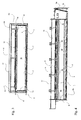
- Figure 3 shows a front view of a cooking device according to the invention in cross section.
- the evacuation of the cooking mist may advantageously be done at the periphery of the mineral facing (3a) of the vault (3).
- the metal structure (10) further allows efficient attachment of the rigid mineral plates constituting the mineral facing (3a) of the vault (3).
- the fixing of the mineral plates constituting the mineral facing (3a) is by any known means on the metal structure (10).
- the mineral facing (s) (3a) of the arch (3) are for example placed on metal supports. These are fixed by screwing on the metal structure (10).
- the mineral facings (4a, 5a, 6a) are for example made of fiber cement or any other mineral material for the realization of rigid plates and supporting high temperatures.
- FIG. 4 represents a longitudinal section of an exemplary embodiment of a cooking device according to the invention, showing a cooking chamber (1) whose internal volume is substantially identical to that which is known in the chambers of baking bread ovens.
- the zone of cantonment (14) of the fogs allowing to influence substantially the cooking in association with the mineral facing (3a, 4a, 5a, 6a), has a smaller size compared to the bulk of a traditional oven allowing to get the same cooking results.
- the box area (14) increases only slightly the overall size of a cooking device according to the invention compared to a cooking chamber of a current oven.
- the cooking device according to the invention thus makes it possible to achieve unexpected cooking results with cooking chambers (1) having a reduced internal volume.
Landscapes
- Life Sciences & Earth Sciences (AREA)
- Engineering & Computer Science (AREA)
- Food Science & Technology (AREA)
- Baking, Grill, Roasting (AREA)
Abstract
- au moins une chambre de cuisson (1) délimitée par une sole (2), une voûte (3), deux parois latérales (4, 5), une paroi arrière (6) et un volet pivotant (19) mobile entre une position d'ouverture et une position de fermeture d'un accès frontal à la chambre de cuisson (1),
- des éléments chauffants (9) en sole (2) et en voûte (3),
- la sole (2) comportant une dalle de cuisson (7) sur laquelle sont disposés les produits destinés à la cuisson,
- et la voûte (3) comportant au moins un orifice d'évacuation (3b) des buées de cuisson,
Description
- La présente invention se rapporte au domaine technique général des fours de cuisson, et plus particulièrement au domaine technique des fours à pain.
- Ces derniers présentent des conceptions et des formes particulières influençant de façon plus ou moins prononcée les résultats de cuisson. Ces formes particulières des fours sont souvent intimement liés à la région d'utilisation.
- On connaît ainsi à titre d'exemple des fours à pain dont la chambre de cuisson présente un grand volume, permettant d'obtenir un résultat de cuisson déterminé, notamment dans l'aspect et dans l'épaisseur de la croûte du pain. Ces fours sont en général construits avec des briques réfractaires et sont chauffés au feu de bois.
- Avec l'évolution technique et en particulier l'utilisation d'éléments chauffants électriques, les fours à pain ont été plus ou moins standardisés dans bon nombre de régions. Les boulangeries actuelles sont ainsi équipées avec un four comportant une superposition de chambres de cuisson, obturables chacune par un volet pivotant. Chacune des chambre est chauffée individuellement par des éléments chauffants électriques.
- Il est ainsi connu de réaliser un dispositif de cuisson destiné notamment à la cuisson du pain, comportant :
- au moins une chambre de cuisson délimitée par une sole, deux parois latérales, une paroi arrière et un volet pivotant mobile entre une position d'ouverture et une position de fermeture d'un accès frontal à la chambre de cuisson,
- des éléments chauffants de sole et de voûte,
- la sole comportant une dalle de cuisson sur laquelle sont disposés les articles destinés à la cuisson,
- et la voûte comportant au moins un orifice d'évacuation des buées de cuisson.
- Ce type de dispositif de cuisson présente cependant un certain nombre d'inconvénients. En effet, les dispositifs de cuisson existants, notamment dans des fours comportant une superposition de chambres de cuisson, présentent une chambre de cuisson de volume réduit et sensiblement parallélépipédique. Ces chambres de cuisson présentent ainsi une hauteur limitée, juste suffisante pour l'introduction et l'évacuation du pain. On obtient en général une texture et un aspect extérieur des articles et notamment du pain déterminés ainsi qu'une épaisseur de croûte limitée, correspondant aux pains et aux baguettes de pain que l'on connaît actuellement.
- Du fait de l'apparition de buées de cuisson restant en contact avec les articles ou avec le pain pendant des durées prolongées dans la chambre de cuisson, il devient difficile de s'écarter des résultats de cuisson connus actuellement, pour obtenir des pains avec une croûte plus épaisse et une texture mate que l'on pourrait obtenir par exemple avec des fours de très grands volumes tels qu'on les connaît en Italie du Sud. Une telle croûte présente une épaisseur d'environ 1cm et est dépourvue de brillance.
- L'utilisation de tels fours à grand volume n'est plus envisageable à l'heure actuelle sur un plan industriel et économique.
- Le but de la présente invention vise ainsi à réaliser un dispositif de cuisson permettant de par sa conformation d'obtenir des pains ou autres articles de cuisson dont l'aspect et la texture ou la qualité se démarque de ce que l'on connaît habituellement et de ce que l'on est capable de faire avec des fours à pain existants et fabriqués actuellement.
- Un but complémentaire de la présente invention vise à réaliser un dispositif de cuisson ne présentant pas les inconvénients mentionnés ci-dessus et pouvant être intégré dans un four actuel comportant par exemple une superposition de chambres de cuisson. Un tel dispositif de cuisson doit être réalisable de préférence en effectuant des adaptations sur des fours existants.
- Selon l'invention, le dispositif comporte d'une part une zone de cantonnement des buées de cuisson dans laquelle débouche l'orifice d'évacuation, ladite zone de cantonnement étant localisée entre la voûte et une paroi supérieure située au-dessus de ladite voûte, et d'autre part un parement minéral recouvrant à l'intérieur de la chambre de cuisson au moins partiellement les parois latérales et la voûte. Par parement minéral il convient d'entendre tout revêtement minéral rigide susceptible d'être fixé sur ou contre des parois et dont les propriétés physiques permettent de produire un rayonnement thermique le plus proche possible du rayonnement émis par des briques réfractaires utilisées dans des fours maçonnés traditionnels.
- Avec le dispositif conforme à l'invention, on peut ainsi s'affranchir des inconvénients liés à une chambre de cuisson de dimensions trop réduites telles qu'on les connaît dans les fours actuels. Le dispositif selon l'invention permet ainsi d'obtenir des résultats de cuisson que l'on ne pourrait pas atteindre avec les fours actuels dans lesquels les articles destinés à la cuisson restent de façon prolongée en contact avec les buées de cuisson.
- La zone de cantonnement, située au-dessus de la chambre de cuisson favorise l'éloignement rapide des buées issues de la cuisson de l'article à cuire. Une fois arrivées dans la zone de cantonnement, les buées peuvent s'échapper par un effet de tirage naturel ou de convection naturelle.
- On obtient ainsi un avantage complémentaire dans la mesure où les pertes caloriques sont substantiellement réduites par rapport aux pertes caloriques des fours actuels disposant d'une extraction forcée des buées, par exemple par ventilation.
- A titre d'exemple, le dispositif conforme à l'invention comporte une pluralité d'orifices d'évacuation. Ces derniers sont par exemple agencés sous forme de passages à la périphérie de la voûte.
- Selon un exemple de réalisation, les éléments chauffants sont des résistances électriques. Les résistances électriques de voûte s'étendent de préférence sensiblement horizontalement et dans le bas de la zone de cantonnement.
- Selon un exemple de réalisation, la zone de cantonnement comporte un moyen d'évacuation des buées de cuisson. Ce moyen d'évacuation est par exemple une ouverture d'évacuation ménagée dans la paroi supérieure du dispositif.
- Selon un exemple de réalisation, la paroi arrière est également recouverte à l'intérieur de la chambre de cuisson au moins partiellement avec un parement minéral.
- Selon un exemple de réalisation, le parement minéral fixé en voûte comporte un assemblage ou une juxtaposition de plaques modulaires, lesquelles cachent les éléments chauffants. Les orifices d'évacuation sont alors agencés sous forme de passages à la périphérie des plaques modulaires du parement minéral de la voûte. Les articles ou produits à cuire ne sont ainsi pas soumis directement au rayonnement infrarouge pénétrant émis par les résistances électriques constitutives des éléments chauffants. Cela favorise l'obtention d'une croûte épaisse car l'énergie est davantage concentrée en surface. L'évaporation d'eau plus localisée en surface contribue à la formation d'une croûte plus épaisse.
- Selon un exemple de réalisation, le parement minéral est constitué de fibrociment minéral. Ce matériau présente une excellente résistance mécanique à des températures comprises entre 250°C et 350°C.
- Le dispositif conforme à l'invention peut comporter une pluralité d'orifices d'évacuation débouchant dans la zone de cantonnement.
- La présente invention concerne également un four comportant au moins un dispositif de cuisson tel que décrit ci-dessus.
- En particulier, l'invention concerne un four comportant plusieurs chambres de cuissons superposées et au moins un dispositif de cuisson tel que décrit ci-dessus.
- D'autres caractéristiques et avantages ressortiront également de la description détaillée figurant ci-après en référence aux dessins annexés à titre d'exemple non limitatif, dans lesquels :
- la figure 1 est une représentation en perspective partielle d'un exemple de réalisation du dispositif de cuisson conforme à l'invention ;
- la figure 2 est une vue en perspective et en coupe longitudinale du dispositif de la figure 1 ;
- la figure 3 est une vue frontale d'une coupe transversale d'un dispositif de cuisson conforme à l'invention;
- la figure 4 est une vue latérale d'une coupe longitudinale d'un dispositif de cuisson conforme à l'invention.
- La figure 1 décrit un exemple de réalisation d'un dispositif conforme à l'invention. Le dispositif est représenté seul et dépourvu de tout habillage extérieur. On peut ainsi à titre d'exemple compléter une superposition de chambres de cuisson telles qu'on les connaît dans des fours classiques avec un dispositif conforme à l'invention.
- Le dispositif de cuisson comporte une chambre de cuisson (1) délimitée par une sole (2), une voûte (3) et latéralement par des parois latérales (4) et (5). Une paroi arrière (6) réalise le fond de la chambre de cuisson (1).
- La chambre de cuisson (1) est délimitée extérieurement par des parois métalliques. La sole (2) comporte également une dalle de cuisson (7) réalisée dans une matière minérale, par exemple en fibrociment.
- C'est sur cette dalle de cuisson (7) que reposent les articles, notamment la pâte destinée à la cuisson. Pour des raisons de construction et de facilité d'assemblage la dalle de cuisson (7) peut être réalisée en deux ou en plusieurs parties tel que cela est représenté à la figure 1.
- La sole (2) comporte également une paroi métallique (8) s'étendant sous la dalle de cuisson (7) et dans ou sur laquelle sont agencés des éléments chauffants (9) du type résistances électriques.
- La voûte (3) comporte également un parement minéral (3a) derrière lequel sont agencés les éléments chauffants (9). Le parement minéral (3a) est par exemple constitué d'un assemblage ou d'une juxtaposition de plaques modulaires cachant les éléments chauffants (9) et fixés sur une structure métallique (10). Cette dernière est de préférence fixée par l'intermédiaire de goujons (11) ou tout autre moyen de fixation à une paroi supérieure (12) de manière à délimiter un espace intérieur entre la voûte (3) et la paroi supérieure (12). La paroi supérieure (12) est également surmontée de traverses de rigidification (18) sur lesquelles sont fixés les goujons (11). Des prolongements latéraux (15) et (16) des parois latérales respectives (4) et (5) permettent de confiner l'espace intérieur au-dessus de la voûte (3), ledit espace intérieur constituant ainsi une zone de cantonnement (14) des buées de cuisson. Par zone de cantonnement (14) il convient d'entendre tout volume ou espace clos en communication avec la chambre de cuisson (1) vers laquelle sont amenées les buées issues de la cuisson. Ces dernières ne restent donc pas en contact prolongé avec les articles à cuire dans la chambre de cuisson (1).
- Des passages ou des orifices d'évacuation (3b) ménagés dans la voûte (3) et en particulier dans le parement minéral (3a) associé à la voûte (3) permettent aux buées de cuisson d'être évacuées rapidement vers la zone de cantonnement (14). Les buées de cuisson s'acheminant dans cette zone de cantonnement (14) sont de préférence en contact direct avec les éléments chauffants (9) qui y sont disposés. On obtient ainsi un assèchement au moins partiel des buées de cuisson.
- La zone de cantonnement (14) est par exemple reliée à un moyen d'évacuation (17) des buées de cuisson, et ce par l'intermédiaire d'une ouverture ménagée dans la paroi supérieure (12). L'évacuation se fait de façon naturelle, sans moyen d'extraction du type ventilation.
- Les parois latérales (4) et (5) sont également recouvertes à l'intérieur de la chambre de cuisson (1), d'un parement minéral (4a, 5a) à l'instar de la voûte (3).
- A titre d'exemple, la paroi arrière (6) peut également être pourvue d'un parement minéral correspondant (6a) à l'intérieur de la chambre de cuisson (1). On pourra se reporter par exemple à la figure 4.
- Le dispositif de cuisson comporte également un volet pivotant mobile (19), entre une position d'ouverture et une position de fermeture d'un accès frontal à la chambre de cuisson (1). Ce volet pivotant (19) peut également selon une variante de réalisation être pourvu sur sa face interne d'un parement minéral (19a). Les parements minéraux (4a, 5a, 6a et 19a) présentent par exemple une épaisseur comprise entre 20 mm et 25 mm.
- La figure 3 représente selon une vue frontale un dispositif de cuisson conforme à l'invention en coupe transversale. L'évacuation des buées de cuisson peut avantageusement se faire à la périphérie du parement minéral (3a) de la voûte (3). La structure métallique (10) permet en outre une fixation efficace des plaques rigides minérales constituant le parement minéral (3a) de la voûte (3). La fixation des plaques minérales, constituant le parement minéral (3a), se fait par tous moyens connus sur la structure métallique (10). Le ou les parements minéraux (3a) de la voûte (3) sont par exemple posés sur des supports métalliques. Ces derniers sont fixés par vissage sur la structure métallique (10).
- Les parements minéraux (4a, 5a, 6a) sont par exemple réalisés en fibrociment ou en tout autre matériau minéral permettant la réalisation de plaques rigides et supportant des températures élevées.
- La figure 4 représentant une coupe longitudinale d'un exemple de réalisation d'un dispositif de cuisson conforme à l'invention représente une chambre de cuisson (1) dont le volume interne est sensiblement identique à celui que l'on connaît dans les chambres de cuisson de fours à pain actuels. La zone de cantonnement (14) des buées permettant d'influencer substantiellement la cuisson en association avec les parement minéraux (3a, 4a, 5a, 6a), présente un encombrement réduit par rapport à l'encombrement d'un four traditionnel permettant d'obtenir les mêmes résultats de cuisson. La zone de cantonnement (14) n'augmente que faiblement l'encombrement global d'un dispositif de cuisson conforme à l'invention par rapport à une chambre de cuisson d'un four actuel.
- Le dispositif de cuisson conforme à l'invention permet ainsi d'atteindre des résultats de cuisson inattendus avec des chambres de cuisson (1) présentant un volume interne réduit.
Claims (12)
- Dispositif de cuisson destiné notamment à la cuisson du pain, comportant :- au moins une chambre de cuisson (1) délimitée par une sole (2), une voûte (3), deux parois latérales (4, 5), une paroi arrière (6) et un volet pivotant (19) mobile entre une position d'ouverture et une position de fermeture d'un accès frontal à la chambre de cuisson (1),- des éléments chauffants (9) en sole (2) et en voûte (3),- la sole (2) comportant une dalle de cuisson (7) sur laquelle sont disposés les produits destinés à la cuisson,- et la voûte (3) comportant au moins un orifice d'évacuation (3b) des buées de cuisson,caractérisé en ce qu'il comporte d'une part une zone de cantonnement (14) des buées de cuisson dans laquelle débouche l'orifice d'évacuation (3b), ladite zone de cantonnement (14) étant localisée entre la voûte (3) et une paroi supérieure (12) située au-dessus de ladite voûte (3), et d'autre part un parement minéral (3a, 4a, 5a) recouvrant à l'intérieur de la chambre de cuisson (1) au moins partiellement les parois latérales (4, 5) et la voûte (3).
- Dispositif selon la revendication 1, caractérisé en ce que les éléments chauffants (9) sont des résistances électriques.
- Dispositif selon la revendication 2, caractérisé en ce que les résistances électriques de voûte (3) s'étendent sensiblement horizontalement dans le bas de la zone de cantonnement (14).
- Dispositif selon l'une quelconque des revendications 1 à 3, caractérisé en ce que la zone de cantonnement (14) comporte un moyen d'évacuation (17) des buées issues de la cuisson.
- Dispositif selon l'une quelconque des revendications 1 à 4, caractérisé en ce que la paroi arrière (6) est également recouverte à l'intérieur de la chambre de cuisson (1) au moins partiellement avec un parement minéral (6a).
- Dispositif selon l'une quelconque des revendications 1 à 5, caractérisé en ce que le parement minéral (3a) fixé en voûte (3) comporte un assemblage ou une juxtaposition de plaques modulaires, lesquelles cachent les éléments chauffants (9).
- Dispositif selon l'une quelconque des revendications 1 à 6, caractérisé en ce que le parement minéral (3a, 4a, 5a, 6a) est constitué de fibrociment minéral.
- Dispositif selon l'une quelconque des revendications 1 à 7, caractérisé en ce que la voûte (3) comporte une pluralité d'orifices d'évacuation (3b) débouchant dans la zone de cantonnement (14).
- Dispositif selon la revendication 8, caractérisé en ce que les orifices d'évacuation (3b) sont agencés sous forme de passages à la périphérie de la voûte (3).
- Dispositif selon les revendications 6 et 8, caractérisé en ce que les orifices d'évacuation (3b) sont agencés sous forme de passages à la périphérie des plaques modulaires du parement minéral (3a) en voûte (3).
- Four comportant au moins un dispositif de cuisson conforme à l'une quelconque des revendications 1 à 10.
- Four comportant plusieurs chambres de cuisson superposées, et au moins un dispositif de cuisson selon l'une quelconque des revendications 1 à 10.
Priority Applications (2)
| Application Number | Priority Date | Filing Date | Title |
|---|---|---|---|
| EP06290779A EP1854357B1 (fr) | 2006-05-11 | 2006-05-11 | Dispositif de cuisson, notamment de pain, et four comportant un tel dispositif |
| AT06290779T ATE548915T1 (de) | 2006-05-11 | 2006-05-11 | Backvorrichtung, insbesondere für brot, und ofen mit einer solchen vorrichtung |
Applications Claiming Priority (1)
| Application Number | Priority Date | Filing Date | Title |
|---|---|---|---|
| EP06290779A EP1854357B1 (fr) | 2006-05-11 | 2006-05-11 | Dispositif de cuisson, notamment de pain, et four comportant un tel dispositif |
Publications (2)
| Publication Number | Publication Date |
|---|---|
| EP1854357A1 true EP1854357A1 (fr) | 2007-11-14 |
| EP1854357B1 EP1854357B1 (fr) | 2012-03-14 |
Family
ID=37491799
Family Applications (1)
| Application Number | Title | Priority Date | Filing Date |
|---|---|---|---|
| EP06290779A Not-in-force EP1854357B1 (fr) | 2006-05-11 | 2006-05-11 | Dispositif de cuisson, notamment de pain, et four comportant un tel dispositif |
Country Status (2)
| Country | Link |
|---|---|
| EP (1) | EP1854357B1 (fr) |
| AT (1) | ATE548915T1 (fr) |
Citations (9)
| Publication number | Priority date | Publication date | Assignee | Title |
|---|---|---|---|---|
| CH87556A (de) * | 1920-06-26 | 1920-12-16 | Lorenz Gustav | Kombinierter Backofen. |
| CH87958A (de) * | 1920-02-10 | 1921-04-01 | E Schaer | Elektrischer Backofen. |
| CH89549A (de) * | 1920-04-14 | 1921-06-01 | Imbach Louis | Elektrischer Backofen. |
| DE532389C (de) * | 1928-10-20 | 1931-08-27 | Wilhelm Rinau | Aus verschiedenartigen Baustoffen bestehende Waermespeicherplatte fuer Back- und Trockenoefen |
| GB469250A (en) * | 1936-01-24 | 1937-07-22 | Joseph Knatt | Improvements in the arrangement and construction of electric ovens |
| CH195061A (de) * | 1937-03-03 | 1938-01-15 | Aeschbach F Ag | Bäckerei- und Konditoreiofen. |
| CH337161A (de) * | 1955-04-14 | 1959-03-31 | Glanzmann Moritz | Elektrisch beheizter Backofen |
| FR2425804A1 (fr) * | 1978-05-18 | 1979-12-14 | Bongard Et Cie Fils Oscar | Four electrique a etages multiples a elements modulaires, pour boulangerie, patisserie, ou analogue |
| FR2740660A1 (fr) * | 1995-11-07 | 1997-05-09 | Guyon Henri | Four de boulangerie et de patisserie |
-
2006
- 2006-05-11 AT AT06290779T patent/ATE548915T1/de active
- 2006-05-11 EP EP06290779A patent/EP1854357B1/fr not_active Not-in-force
Patent Citations (9)
| Publication number | Priority date | Publication date | Assignee | Title |
|---|---|---|---|---|
| CH87958A (de) * | 1920-02-10 | 1921-04-01 | E Schaer | Elektrischer Backofen. |
| CH89549A (de) * | 1920-04-14 | 1921-06-01 | Imbach Louis | Elektrischer Backofen. |
| CH87556A (de) * | 1920-06-26 | 1920-12-16 | Lorenz Gustav | Kombinierter Backofen. |
| DE532389C (de) * | 1928-10-20 | 1931-08-27 | Wilhelm Rinau | Aus verschiedenartigen Baustoffen bestehende Waermespeicherplatte fuer Back- und Trockenoefen |
| GB469250A (en) * | 1936-01-24 | 1937-07-22 | Joseph Knatt | Improvements in the arrangement and construction of electric ovens |
| CH195061A (de) * | 1937-03-03 | 1938-01-15 | Aeschbach F Ag | Bäckerei- und Konditoreiofen. |
| CH337161A (de) * | 1955-04-14 | 1959-03-31 | Glanzmann Moritz | Elektrisch beheizter Backofen |
| FR2425804A1 (fr) * | 1978-05-18 | 1979-12-14 | Bongard Et Cie Fils Oscar | Four electrique a etages multiples a elements modulaires, pour boulangerie, patisserie, ou analogue |
| FR2740660A1 (fr) * | 1995-11-07 | 1997-05-09 | Guyon Henri | Four de boulangerie et de patisserie |
Also Published As
| Publication number | Publication date |
|---|---|
| EP1854357B1 (fr) | 2012-03-14 |
| ATE548915T1 (de) | 2012-03-15 |
Similar Documents
| Publication | Publication Date | Title |
|---|---|---|
| EP3706576B1 (fr) | Appareil de cuisson pour preparations patissieres | |
| EP0621000B1 (fr) | Appareil de cuisson à plaque de cuisson pourvue d'ouvertures | |
| FR2585808A1 (fr) | Un four de cuisson-rotissoire | |
| Genitha et al. | Design, fabrication and performance evaluation of domestic gas oven | |
| EP2020182B1 (fr) | Accessoire de cuisson et appareil associé | |
| EP1854357B1 (fr) | Dispositif de cuisson, notamment de pain, et four comportant un tel dispositif | |
| WO2006100376A1 (fr) | Dispositif destine a la cuisson de pizzas et de grillades | |
| KR101564624B1 (ko) | 고구마 구이장치 | |
| FR3066885A1 (fr) | Four d'exterieur a entree des flammes dans l'enceinte de cuisson | |
| EP0490774A1 (fr) | Porte pour four de cuisson à usage domestique | |
| FR2463363A1 (fr) | Four de cuisson d'aliments multifonctionnel | |
| KR101064045B1 (ko) | 휴대용 번철 | |
| EP2361511A1 (fr) | Dispositif de décongelation, réchauffage et cuisson d'un produit alimentaire, notamment d'une pâte alimentaire surgelée | |
| EP1753294B1 (fr) | Four de cuisson de produits de boulangerie, viennoiserie, patisserie ou analogue | |
| EP2944738B1 (fr) | Elément de construction destiné notamment à la fabrication de parois porteuses ou de séparation d'un bâtiment | |
| EP1947388A1 (fr) | Moufle de cuisson en verre pour enceinte de cuisson et enceinte équipée d'un tel moufle | |
| JP2001148998A (ja) | 電気オーブン及び焼成方法 | |
| FR2717566A1 (fr) | Four de cuisson à bois, notamment pour la cuisson de produits de boulangerie, pizzas, tartes ou analogues. | |
| FR2531839A1 (fr) | Four de boulangerie a soles fixes et a chariot | |
| FR2597301A1 (fr) | Dalle de cuisson en materiau ceramique et four la comportant. | |
| FR3014290A1 (fr) | Four a gaz transportable | |
| BE1029752B1 (fr) | Dispositif de cuisson multifonction pour usage en exterieur | |
| FR2935466A3 (fr) | Four | |
| FR3086139A1 (fr) | Moule a paroi variable | |
| FR2696630A1 (fr) | Four de cuisson pour produits alimentaires type pain... etc. |
Legal Events
| Date | Code | Title | Description |
|---|---|---|---|
| PUAI | Public reference made under article 153(3) epc to a published international application that has entered the european phase |
Free format text: ORIGINAL CODE: 0009012 |
|
| AK | Designated contracting states |
Kind code of ref document: A1 Designated state(s): AT BE BG CH CY CZ DE DK EE ES FI FR GB GR HU IE IS IT LI LT LU LV MC NL PL PT RO SE SI SK TR |
|
| AX | Request for extension of the european patent |
Extension state: AL BA HR MK YU |
|
| 17P | Request for examination filed |
Effective date: 20071115 |
|
| AKX | Designation fees paid |
Designated state(s): AT BE BG CH CY CZ DE DK EE ES FI FR GB GR HU IE IS IT LI LT LU LV MC NL PL PT RO SE SI SK TR |
|
| GRAP | Despatch of communication of intention to grant a patent |
Free format text: ORIGINAL CODE: EPIDOSNIGR1 |
|
| RTI1 | Title (correction) |
Free format text: BAKING DEVICE PARTICULARLY FOR BREAD AND OVEN COMPRISING SAID DEVICE |
|
| GRAS | Grant fee paid |
Free format text: ORIGINAL CODE: EPIDOSNIGR3 |
|
| GRAA | (expected) grant |
Free format text: ORIGINAL CODE: 0009210 |
|
| AK | Designated contracting states |
Kind code of ref document: B1 Designated state(s): AT BE BG CH CY CZ DE DK EE ES FI FR GB GR HU IE IS IT LI LT LU LV MC NL PL PT RO SE SI SK TR |
|
| REG | Reference to a national code |
Ref country code: GB Ref legal event code: FG4D Free format text: NOT ENGLISH |
|
| REG | Reference to a national code |
Ref country code: CH Ref legal event code: EP Ref country code: AT Ref legal event code: REF Ref document number: 548915 Country of ref document: AT Kind code of ref document: T Effective date: 20120315 |
|
| REG | Reference to a national code |
Ref country code: IE Ref legal event code: FG4D Free format text: LANGUAGE OF EP DOCUMENT: FRENCH |
|
| REG | Reference to a national code |
Ref country code: DE Ref legal event code: R096 Ref document number: 602006028155 Country of ref document: DE Effective date: 20120510 |
|
| REG | Reference to a national code |
Ref country code: NL Ref legal event code: VDEP Effective date: 20120314 |
|
| PG25 | Lapsed in a contracting state [announced via postgrant information from national office to epo] |
Ref country code: LT Free format text: LAPSE BECAUSE OF FAILURE TO SUBMIT A TRANSLATION OF THE DESCRIPTION OR TO PAY THE FEE WITHIN THE PRESCRIBED TIME-LIMIT Effective date: 20120314 |
|
| LTIE | Lt: invalidation of european patent or patent extension |
Effective date: 20120314 |
|
| PG25 | Lapsed in a contracting state [announced via postgrant information from national office to epo] |
Ref country code: LV Free format text: LAPSE BECAUSE OF FAILURE TO SUBMIT A TRANSLATION OF THE DESCRIPTION OR TO PAY THE FEE WITHIN THE PRESCRIBED TIME-LIMIT Effective date: 20120314 Ref country code: FI Free format text: LAPSE BECAUSE OF FAILURE TO SUBMIT A TRANSLATION OF THE DESCRIPTION OR TO PAY THE FEE WITHIN THE PRESCRIBED TIME-LIMIT Effective date: 20120314 Ref country code: GR Free format text: LAPSE BECAUSE OF FAILURE TO SUBMIT A TRANSLATION OF THE DESCRIPTION OR TO PAY THE FEE WITHIN THE PRESCRIBED TIME-LIMIT Effective date: 20120615 |
|
| REG | Reference to a national code |
Ref country code: AT Ref legal event code: MK05 Ref document number: 548915 Country of ref document: AT Kind code of ref document: T Effective date: 20120314 |
|
| PG25 | Lapsed in a contracting state [announced via postgrant information from national office to epo] |
Ref country code: CY Free format text: LAPSE BECAUSE OF FAILURE TO SUBMIT A TRANSLATION OF THE DESCRIPTION OR TO PAY THE FEE WITHIN THE PRESCRIBED TIME-LIMIT Effective date: 20120314 |
|
| PG25 | Lapsed in a contracting state [announced via postgrant information from national office to epo] |
Ref country code: RO Free format text: LAPSE BECAUSE OF FAILURE TO SUBMIT A TRANSLATION OF THE DESCRIPTION OR TO PAY THE FEE WITHIN THE PRESCRIBED TIME-LIMIT Effective date: 20120314 Ref country code: IS Free format text: LAPSE BECAUSE OF FAILURE TO SUBMIT A TRANSLATION OF THE DESCRIPTION OR TO PAY THE FEE WITHIN THE PRESCRIBED TIME-LIMIT Effective date: 20120714 Ref country code: PL Free format text: LAPSE BECAUSE OF FAILURE TO SUBMIT A TRANSLATION OF THE DESCRIPTION OR TO PAY THE FEE WITHIN THE PRESCRIBED TIME-LIMIT Effective date: 20120314 Ref country code: SI Free format text: LAPSE BECAUSE OF FAILURE TO SUBMIT A TRANSLATION OF THE DESCRIPTION OR TO PAY THE FEE WITHIN THE PRESCRIBED TIME-LIMIT Effective date: 20120314 Ref country code: SE Free format text: LAPSE BECAUSE OF FAILURE TO SUBMIT A TRANSLATION OF THE DESCRIPTION OR TO PAY THE FEE WITHIN THE PRESCRIBED TIME-LIMIT Effective date: 20120314 Ref country code: CZ Free format text: LAPSE BECAUSE OF FAILURE TO SUBMIT A TRANSLATION OF THE DESCRIPTION OR TO PAY THE FEE WITHIN THE PRESCRIBED TIME-LIMIT Effective date: 20120314 Ref country code: EE Free format text: LAPSE BECAUSE OF FAILURE TO SUBMIT A TRANSLATION OF THE DESCRIPTION OR TO PAY THE FEE WITHIN THE PRESCRIBED TIME-LIMIT Effective date: 20120314 |
|
| BERE | Be: lapsed |
Owner name: BONGARD (S.A.) Effective date: 20120531 |
|
| PG25 | Lapsed in a contracting state [announced via postgrant information from national office to epo] |
Ref country code: PT Free format text: LAPSE BECAUSE OF FAILURE TO SUBMIT A TRANSLATION OF THE DESCRIPTION OR TO PAY THE FEE WITHIN THE PRESCRIBED TIME-LIMIT Effective date: 20120716 Ref country code: SK Free format text: LAPSE BECAUSE OF FAILURE TO SUBMIT A TRANSLATION OF THE DESCRIPTION OR TO PAY THE FEE WITHIN THE PRESCRIBED TIME-LIMIT Effective date: 20120314 |
|
| PG25 | Lapsed in a contracting state [announced via postgrant information from national office to epo] |
Ref country code: MC Free format text: LAPSE BECAUSE OF NON-PAYMENT OF DUE FEES Effective date: 20120531 |
|
| REG | Reference to a national code |
Ref country code: CH Ref legal event code: PL |
|
| PLBE | No opposition filed within time limit |
Free format text: ORIGINAL CODE: 0009261 |
|
| STAA | Information on the status of an ep patent application or granted ep patent |
Free format text: STATUS: NO OPPOSITION FILED WITHIN TIME LIMIT |
|
| PG25 | Lapsed in a contracting state [announced via postgrant information from national office to epo] |
Ref country code: NL Free format text: LAPSE BECAUSE OF FAILURE TO SUBMIT A TRANSLATION OF THE DESCRIPTION OR TO PAY THE FEE WITHIN THE PRESCRIBED TIME-LIMIT Effective date: 20120314 Ref country code: LI Free format text: LAPSE BECAUSE OF NON-PAYMENT OF DUE FEES Effective date: 20120531 Ref country code: DK Free format text: LAPSE BECAUSE OF FAILURE TO SUBMIT A TRANSLATION OF THE DESCRIPTION OR TO PAY THE FEE WITHIN THE PRESCRIBED TIME-LIMIT Effective date: 20120314 Ref country code: CH Free format text: LAPSE BECAUSE OF NON-PAYMENT OF DUE FEES Effective date: 20120531 Ref country code: AT Free format text: LAPSE BECAUSE OF FAILURE TO SUBMIT A TRANSLATION OF THE DESCRIPTION OR TO PAY THE FEE WITHIN THE PRESCRIBED TIME-LIMIT Effective date: 20120314 |
|
| 26N | No opposition filed |
Effective date: 20121217 |
|
| GBPC | Gb: european patent ceased through non-payment of renewal fee |
Effective date: 20120614 |
|
| REG | Reference to a national code |
Ref country code: IE Ref legal event code: MM4A |
|
| PG25 | Lapsed in a contracting state [announced via postgrant information from national office to epo] |
Ref country code: BE Free format text: LAPSE BECAUSE OF NON-PAYMENT OF DUE FEES Effective date: 20120531 |
|
| REG | Reference to a national code |
Ref country code: FR Ref legal event code: ST Effective date: 20130131 |
|
| REG | Reference to a national code |
Ref country code: DE Ref legal event code: R119 Ref document number: 602006028155 Country of ref document: DE Effective date: 20121201 |
|
| REG | Reference to a national code |
Ref country code: FR Ref legal event code: D3 Effective date: 20130220 |
|
| PG25 | Lapsed in a contracting state [announced via postgrant information from national office to epo] |
Ref country code: GB Free format text: LAPSE BECAUSE OF NON-PAYMENT OF DUE FEES Effective date: 20120614 Ref country code: IE Free format text: LAPSE BECAUSE OF NON-PAYMENT OF DUE FEES Effective date: 20120511 Ref country code: ES Free format text: LAPSE BECAUSE OF FAILURE TO SUBMIT A TRANSLATION OF THE DESCRIPTION OR TO PAY THE FEE WITHIN THE PRESCRIBED TIME-LIMIT Effective date: 20120625 |
|
| PGRI | Patent reinstated in contracting state [announced from national office to epo] |
Ref country code: FR Effective date: 20130220 |
|
| PGRI | Patent reinstated in contracting state [announced from national office to epo] |
Ref country code: FR Effective date: 20130220 |
|
| PG25 | Lapsed in a contracting state [announced via postgrant information from national office to epo] |
Ref country code: DE Free format text: LAPSE BECAUSE OF NON-PAYMENT OF DUE FEES Effective date: 20121201 |
|
| PG25 | Lapsed in a contracting state [announced via postgrant information from national office to epo] |
Ref country code: BG Free format text: LAPSE BECAUSE OF FAILURE TO SUBMIT A TRANSLATION OF THE DESCRIPTION OR TO PAY THE FEE WITHIN THE PRESCRIBED TIME-LIMIT Effective date: 20120614 |
|
| PG25 | Lapsed in a contracting state [announced via postgrant information from national office to epo] |
Ref country code: TR Free format text: LAPSE BECAUSE OF FAILURE TO SUBMIT A TRANSLATION OF THE DESCRIPTION OR TO PAY THE FEE WITHIN THE PRESCRIBED TIME-LIMIT Effective date: 20120314 |
|
| PG25 | Lapsed in a contracting state [announced via postgrant information from national office to epo] |
Ref country code: LU Free format text: LAPSE BECAUSE OF NON-PAYMENT OF DUE FEES Effective date: 20120511 |
|
| PG25 | Lapsed in a contracting state [announced via postgrant information from national office to epo] |
Ref country code: HU Free format text: LAPSE BECAUSE OF FAILURE TO SUBMIT A TRANSLATION OF THE DESCRIPTION OR TO PAY THE FEE WITHIN THE PRESCRIBED TIME-LIMIT Effective date: 20060511 |
|
| REG | Reference to a national code |
Ref country code: FR Ref legal event code: PLFP Year of fee payment: 11 |
|
| REG | Reference to a national code |
Ref country code: FR Ref legal event code: PLFP Year of fee payment: 12 |
|
| REG | Reference to a national code |
Ref country code: FR Ref legal event code: PLFP Year of fee payment: 13 |
|
| PGFP | Annual fee paid to national office [announced via postgrant information from national office to epo] |
Ref country code: IT Payment date: 20180514 Year of fee payment: 13 Ref country code: FR Payment date: 20180427 Year of fee payment: 13 |
|
| PG25 | Lapsed in a contracting state [announced via postgrant information from national office to epo] |
Ref country code: IT Free format text: LAPSE BECAUSE OF NON-PAYMENT OF DUE FEES Effective date: 20190511 |
|
| PG25 | Lapsed in a contracting state [announced via postgrant information from national office to epo] |
Ref country code: FR Free format text: LAPSE BECAUSE OF NON-PAYMENT OF DUE FEES Effective date: 20190531 |