EP1908719A1 - Ascenseur - Google Patents
Ascenseur Download PDFInfo
- Publication number
- EP1908719A1 EP1908719A1 EP06781579A EP06781579A EP1908719A1 EP 1908719 A1 EP1908719 A1 EP 1908719A1 EP 06781579 A EP06781579 A EP 06781579A EP 06781579 A EP06781579 A EP 06781579A EP 1908719 A1 EP1908719 A1 EP 1908719A1
- Authority
- EP
- European Patent Office
- Prior art keywords
- car
- speed
- motor
- load
- inverter
- Prior art date
- Legal status (The legal status is an assumption and is not a legal conclusion. Google has not performed a legal analysis and makes no representation as to the accuracy of the status listed.)
- Granted
Links
Images


Classifications
-
- B—PERFORMING OPERATIONS; TRANSPORTING
- B66—HOISTING; LIFTING; HAULING
- B66B—ELEVATORS; ESCALATORS OR MOVING WALKWAYS
- B66B1/00—Control systems of elevators in general
- B66B1/24—Control systems with regulation, i.e. with retroactive action, for influencing travelling speed, acceleration, or deceleration
- B66B1/28—Control systems with regulation, i.e. with retroactive action, for influencing travelling speed, acceleration, or deceleration electrical
- B66B1/30—Control systems with regulation, i.e. with retroactive action, for influencing travelling speed, acceleration, or deceleration electrical effective on driving gear, e.g. acting on power electronics, on inverter or rectifier controlled motor
- B66B1/308—Control systems with regulation, i.e. with retroactive action, for influencing travelling speed, acceleration, or deceleration electrical effective on driving gear, e.g. acting on power electronics, on inverter or rectifier controlled motor with AC powered elevator drive
-
- B—PERFORMING OPERATIONS; TRANSPORTING
- B66—HOISTING; LIFTING; HAULING
- B66B—ELEVATORS; ESCALATORS OR MOVING WALKWAYS
- B66B1/00—Control systems of elevators in general
- B66B1/02—Control systems without regulation, i.e. without retroactive action
- B66B1/06—Control systems without regulation, i.e. without retroactive action electric
- B66B1/14—Control systems without regulation, i.e. without retroactive action electric with devices, e.g. push-buttons, for indirect control of movements
-
- B—PERFORMING OPERATIONS; TRANSPORTING
- B66—HOISTING; LIFTING; HAULING
- B66B—ELEVATORS; ESCALATORS OR MOVING WALKWAYS
- B66B1/00—Control systems of elevators in general
- B66B1/24—Control systems with regulation, i.e. with retroactive action, for influencing travelling speed, acceleration, or deceleration
- B66B1/28—Control systems with regulation, i.e. with retroactive action, for influencing travelling speed, acceleration, or deceleration electrical
- B66B1/285—Control systems with regulation, i.e. with retroactive action, for influencing travelling speed, acceleration, or deceleration electrical with the use of a speed pattern generator
Definitions
- the present invention relates to an elevator device having a car whose running speed is variable in accordance with a loading state of the car.
- a conventional elevator control device In a conventional elevator control device, the speed of a car during constant-speed running and the acceleration/deceleration of the car during accelerated/decelerated running are changed in accordance with a load on the car, within a drive range of a motor and an electric component for driving the motor. Thus, a margin of power of the motor is utilized, so the traveling efficiency of the car is improved (e.g., see Patent Document 1).
- Patent Document 1 JP 2003-238037 A
- the present invention has been made to solve the above-mentioned problems, and it is therefore an obj ect of the present invention to obtain an elevator device allowing a car to be operated more efficiently while preventing a drive component from becoming overloaded.
- An elevator device includes: drive means having a drive sheave, a motor for rotating the drive sheave, and a motor driving portion for driving the motor; suspension means looped around the drive sheave; a car and a counterweight that are suspended by the suspension means to be raised/lowered by the drive means; and control means for controlling the motor driving portion, in which the control means monitors a load on at least one component within the drive means while the car is running, generates a control command regarding a running speed of the car in accordance with a state of the load, and outputs the control command to the motor driving portion.
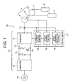
- Fig. 1 is a schematic diagram showing an elevator device according to Embodiment 1 of the present invention.
- a car 1 and a counterweight 2 are raised/lowered within a hoistway by a hoisting machine 3.
- the hoisting machine 3 has a motor 4, a drive sheave 5 that is rotated by the motor 4, a speed detector 6 for detecting a rotational speed of the motor 4 and positions of magnetic poles of the motor 4, and a brake (not shown) for braking rotation of the drive sheave 5.
- the speed detector 6 is, for example, an encoder or a resolver.
- a plurality of main ropes 7 (only one of the main ropes 7 is shown in Fig. 1 ) as suspension means for suspending the car 1 and the counterweight 2 are looped around the drive sheave 5.
- the suspension means are, for example, normal ropes or belt-type ropes.
- a power is supplied from a power supply 10 to the motor 4 via a converter 8 and an inverter 9.
- the converter 8 converts an AC voltage from the power supply 10 into a DC voltage.
- the inverter 9 creates an alternating current with an arbitrary voltage and an arbitrary frequency from the DC voltage generated by the converter 8.
- the inverter 9 performs the switching of the DC voltage to create the alternating current.
- a smoothing capacitor 11 for smoothing a DC output from the converter 8 is connected between the converter 8 and the inverter 9.
- a regenerative resistor 12 and a regenerative switch 13 are connected in parallel to the smoothing capacitor 11.
- the value of a current supplied from the inverter 9 to the motor 4 is detected' by a current detector 14.
- the regenerative resistor 12 consumes a power regenerated during regenerative operation of the hoisting machine 3 as heat.
- the regenerative switch 13 is turned ON to cause a current to flow through the regenerative resistor 12.
- the regenerative switch 13 When the regenerative switch 13 is ON, the current flows through the regenerative resistor 12. Thus, the voltage of the smoothing capacitor 11 drops. Then, when the voltage of the smoothing capacitor 11 drops below a predetermined value, the regenerative switch 13 is turned OFF. Thus, the regenerative resistor 12 is stopped from being supplied with the current, so the voltage of the smoothing capacitor 11 is stopped from dropping.
- the DC voltage input to the inverter 9 is controlled into a prescribed range by turning the regenerative switch 13 ON/OFF in accordance with the voltage of the smoothing capacitor 11.
- the regenerative switch 13 is, for example, a semiconductor switch.
- a motor driving portion 15 for driving the motor 4 has the converter 8, the inverter 9, the smoothing capacitor 11, the regenerative resistor 12, the regenerative switch 13, and a breaker (not shown) for permitting/prohibiting the inputting of a current to the inverter 9.
- Drive means 16 for raising/lowering the car 1 and the counterweight 2 has the hoisting machine 3 and the motor driving portion 15.
- the inverter 9 is controlled by control means 17.
- the control means 17 has a speed command generating portion 18, a speed control portion 19, and a current control portion 20.
- the speed command generating portion 18 generates a speed command for the car 1, namely, a speed command for the hoisting machine 3 in response to a registration of a call from a landing or a call from within the car 1.
- the speed control portion 19 calculates a torque value based on the speed command generated by the speed command generating portion 18 and information from the speed detector 6, such that the rotational speed of the motor 4 coincides with the value of the speed command, and generates a torque command.
- the current control portion 20 controls the inverter 9 based on a current detection signal from the current detector 14 and the torque command from the speed control portion 19. More specifically, the current control portion 20 converts the torque command from the speed control portion 19 into a current command value, and outputs a signal for driving the inverter 9 such that the current value detected by the current detector 14 coincides with the current command value.
- Vector control is adopted in controlling the current of the inverter 9 through the current control portion 20. That is, the current control portion 20 calculates a voltage value to be output by the inverter 9 in accordance with the current command value obtained through conversion of the torque command, the current value of the motor 4 detected by the current detector 14, and positions of the magnetic poles (rotational positions) detected by the speed detector 6, and outputs an ON/OFF switching pattern to a built-in transistor in the inverter 9.
- the control means 17 is constituted by a computer having a calculation processing portion (a CPU), a storage portion (a ROM, a RAM, a hard disk, and the like), and signal input/output portions. That is, the functions of the speed command generating portion 18, the speed control portion 19, and the current control portion 20 are realized by the computer.
- the control means 17 generates a speed command such that the maximum speed of the car 1 and the acceleration of the car 1 are raised to the maximum within a permissible range of the drive means 16 to shorten the running time of the car 1.
- the control means 17 monitors the load on at least one of components within the drive means 16 while the car 1 is running, and generates a control command regarding the running speed of the car 1 without loss of time (on a real-time basis) based on the monitored load.
- the control means 17 raises the running speed of the car 1 until the monitored load reaches a preset threshold.
- the control command regarding the running speed means a command to change the speed of the car 1, for example, a speed command for the car 1 or a speed command for the hoisting machine 3.
- the running speed of the car 1 is limited to an upper limit (Vmax) prescribed according to the performances of safety components such as a buffer (not shown), a brake (not shown), a safety gear (not shown), and a speed governor (not shown). Accordingly, the speed of the car 1 is held at Vmax to make a shift to constant-speed running unless the load monitored by the control means 17 reaches the threshold.
- Vmax an upper limit
- safety components such as a buffer (not shown), a brake (not shown), a safety gear (not shown), and a speed governor (not shown). Accordingly, the speed of the car 1 is held at Vmax to make a shift to constant-speed running unless the load monitored by the control means 17 reaches the threshold.
- the speed command generating portion 18 in Embodiment 1 of the present invention monitors, for example, a current value of the motor 4, namely, a current value detected by the current detector 14 as a load on at least one of the drive components. Then, when the current value of the motor 4 reaches a preset threshold during accelerated running of the car 1, the speed command generating portion 18 generates a control command to cause the car 1 to run at a constant speed.
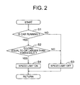
- Fig. 2 is a flowchart showing a speed limit determining operation performed by the speed command generating portion 18 of Fig. 1 .
- the speed command generating portion 18 determines whether or not the car 1 is running (Step S1). When the car 1 is running, the speed command generating portion 18 determines whether or not the load on the monitored component has reached a threshold (Step S2). When the car 1 is not running or when the load does not reach the threshold, the speed command generating portion 18 cancels a speed limit (Step S3). When the load reaches the threshold while the car 1 is running, the speed command generating portion 18 limits the running speed of the car 1 to a speed lower than Vmax. The speed command generating portion 18 repeatedly performs the speed limit determining operation as described above at intervals of a predetermined period.
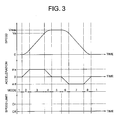
- Fig. 3 is composed of graphs showing changes with time in the running speed of the car 1, the acceleration of the car 1, the running mode of the car 1, and the speed limit state of the car 1, respectively, when no speed limit is imposed on the car 1 by the speed command generating portion 18 of Fig. 1 .
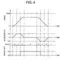
- Fig. 4 is composed of graphs showing changes with time in the running speed of the car 1, the acceleration of the car 1, the running mode of the car 1, and the speed limit state of the car 1, respectively, when a speed limit is imposed on the car 1 by the speed command generating portion 18 of Fig. 1 .
- MODE 2 is a state of acceleration > 0 and jerk > 0.
- MODE 4 is a state of acceleration > 0 and jerk ⁇ 0.
- MODE 5 is a state of constant speed.
- MODE 6 is a state of acceleration ⁇ 0 and jerk ⁇ 0.
- MODE 8 is a state of acceleration ⁇ 0 and jerk > 0.
- the acceleration in MODE 7 is a preset maximum deceleration ⁇ d.
- Fig. 5 is a flowchart showing a mode switchover operation performed by the speed command generating portion 18 of Fig. 1 .
- the speed command generating portion 18 repeatedly performs the mode switchover operation as shown in Fig. 5 at intervals of a predetermined period (a time sufficiently shorter than the running time of the car 1: e.g., 50 milliseconds).
- the speed command generating portion 18 first determines whether or not an activation command has been input to the control means 17 (Step S11) .
- Vc V + ⁇ ⁇ ts
- the speed command generating portion 18 outputs the calculated speed command Vc to the speed control portion 19 (Step S14), thereby terminating a calculation on a current cycle.
- j denotes a jerk
- Vmax denotes a maximum speed in a speed command
- ts denotes a calculation period.
- the acceleration ⁇ obtained through the last calculation is assigned to ⁇ on the right-hand side of the expression (2).
- the speed command generating portion 18 performs the calculation of the expression (1) (Step S13). In this case, the speed command generating portion 18 assigns the speed command Vc obtained through the last calculation to the speed V on the right-hand side of the expression (1), and assigns the acceleration ⁇ calculated according to the expression (2) to the acceleration ⁇ on the right-hand side of the expression (1). Thus, a new speed command Vc is calculated. After that, the speed command generating portion 18 outputs the calculated speed command Vc to the speed control portion 19 (Step S14), thereby terminating the calculation on the current cycle.
- the speed command generating portion 18 determines whether or not the acceleration ⁇ reaches a maximum acceleration ⁇ a (Step S18).
- the speed command generating portion 18 calculates the speed command Vc on the current calculation cycle (Step S13), and outputs the speed command Vc to the speed control portion 19 (Step S14), thereby terminating the calculation on the current cycle.
- the speed command generating portion 18 determines whether or not the speed command Vc is equal to the transition speed Va, and whether or not there is a need to impose a speed limit for the reason that the load on at least one of the components within the drive means 16 has reached the threshold (Step S21).
- the speed command generating portion 18 assigns the acceleration ⁇ obtained through the last calculation to the acceleration ⁇ on the right-hand side of the expression (4).
- the speed command generating portion 18 calculates the speed command Vc on the current calculation cycle (Step S13), and outputs the speed command Vc to the speed control portion 19 (Step S14), thereby terminating the calculation on the current cycle.
- the speed command generating portion 18 determines whether or not the acceleration ⁇ has reached 0 (Step S24).
- the speed command generating portion 18 calculates the speed command Vc on the current calculation cycle (Step S13), and outputs the speed command Vc to the speed control portion 19 (Step S14), thereby terminating the calculation on the current cycle.
- the speed command generating portion 18 calculates the speed command Vc on the current calculation cycle (Step S13), and outputs the speed command Vc to the speed control portion 19 (Step S14), thereby terminating the calculation on the current cycle.
- the speed command generating portion 18 determines whether or not the acceleration ⁇ has reached the preset maximum deceleration ⁇ d (Step S30) .
- the speed command generating portion 18 calculates the speed command Vc on the current calculation cycle (Step S13), and outputs the speed command Vc to the speed control portion 19 (Step S14), thereby terminating the calculation on the current cycle.
- the speed command generating portion 18 calculates the speed command Vc on the current calculation cycle (Step S13), and outputs the speed command Vc to the speed control portion 19 (Step S14), thereby terminating the calculation on the current cycle.
- Fig. 6 is composed of graphs showing changes with time in the load state of at least one of the components of the drive means 16 and the speed of the car 1, respectively, when the car 1 is caused to run through the mode switchover operation of Fig. 5 .
- a threshold A is set lower than a permissible value B of the load on the component. In other words, a predetermined margin is provided between the threshold A and the permissible value B.
- the load on at least one of the components within the drive means 16 is monitored while the car 1 is running, and the control command regarding the running speed of the car 1 is generated in accordance with the state of the load and then output to the motor driving portion 15, instead of generating a speed pattern in accordance with a load within the car 1 when the car 1 starts running. It is therefore possible to operate the car 1 more efficiently while preventing at least one of the drive components from becoming overloaded.
- the control means 17 continuously raises the running speed of the car 1 after the car 1 has started running, and reduces the acceleration of the car 1 when the monitored load reaches the threshold. It is therefore possible to further improve the operating efficiency of the car 1. Further, after the car 1 has started running, the control means 17 raises the acceleration of the car 1 at the predetermined jerk until the acceleration of the car 1 reaches the predetermined acceleration. It is therefore possible to further improve the operating efficiency of the car 1. Still further, when the load on the component reaches the threshold during accelerated running of the car 1, the control means 17 generates the control command to cause the car 1 to run at the constant speed. It is therefore possible to more reliably prevent at least one of the drive components from becoming overloaded.
- Fig. 7 is composed of graphs showing changes with time in the load state of at least one of components of drive means and the speed of a car, respectively, in an elevator device according to Embodiment 2 of the present invention.
- the overall construction of the device is the same as that of Embodiment 1 of the present invention ( Fig. 1 ).
- a threshold A' is set lower than the permissible value B of the load on the component. In other words, a predetermined margin is provided between the threshold A' and the permissible value B.
- Embodiment 2 of the present invention when the load on the component reaches the threshold A' during accelerated running of the car 1, the control means 17 generates a control command, namely, a speed command such that the load is held at the threshold A'. Referring to Fig. 7 , the load on the component reaches the threshold A' at a time point t2, but the speed of the car 1 rises gently after that as well.
- Embodiment 2 of the present invention is identical to Embodiment 1 of the present invention in other constructional details and other details about the method of control.
- the speed command is generated such that the load follows the threshold A'.
- the threshold A' can be set close to the permissible value B. Accordingly, it is possible to achieve a further improvement in operating efficiency.
- the motor current is mentioned as the load on at least one of the components monitored by the control means 17.
- the load on the component is not limited thereto.
- the load monitored by the control means 17 may be a voltage of the motor 4 or a temperature of the motor 4.
- the voltage of the motor 4 can be detected by a voltage detector provided on the motor 4.
- a voltage command value for the inverter 9, which is generated within the control means 17, may be used instead of a detected value of the voltage of the motor 4.
- the temperature of the motor 4 can be detected by a temperature detector provided on the motor 4.
- the temperature of the motor 4 can also be estimated from an integrated value of the current of the motor 4.
- the load monitored by the control means 17 may also be a current of the inverter 9, a temperature of the inverter 9, a switching duty of the inverter 9, or an output voltage of the inverter 9.
- the current of the inverter 9 can be detected by a current detector provided on the inverter 9.
- the temperature of the inverter 9 can be detected by a temperature detector provided on the inverter 9.
- the temperature of the inverter 9 can also be estimated from an integrated value of the current of the inverter 9.
- the switching duty of the inverter 9 can be calculated from a voltage command value for the inverter 9 which is generated within the control means 17.
- the output voltage of the inverter 9 can be detected by a voltage detector provided on the inverter 9.
- a voltage command value for the inverter 9, which is generated within the control means 17, may be used instead of a detected value of the output voltage of the inverter 9.
- the load monitored by the control means 17 may be at least one of a d-axis current and a q-axis current, which have been obtained by converting a current supplied to the motor 4 into values in the Cartesian coordinate system. Still further, the load monitored by the control means 17 may be at least one of a d-axis current command and a q-axis current command in the Cartesian coordinate system, which have been generated to control the inverter 9.
- the load monitored by the control means 17 may be a power supplied from the inverter 9 to the motor 4.
- This power can be calculated as q-axis current (or q-axis current command) x car speed (or speed command value).
- the power can also be calculated as current measurement value (or current command value) x speed measurement value (or speed command value).
- the power can also be calculated as current measurement value (or current command value) x voltage measurement value (or voltage command value).
- the load monitored by the control means 17 may be a temperature of the regenerative resistor 12.
- the temperature of the regenerative resistor 12 can be detected by a temperature detector provided on the regenerative resistor 12.
- the temperature of the regenerative resistor 12 can also be estimated from a state (switching duty) of the regenerative switch 13.
- the load monitored by the control means 17 may be a regenerative power obtained through the regenerative resistor 12.
- the regenerative power can be estimated from a state (switching duty) of the regenerative switch 13.
- the load monitored by the control means 17 may be a current flowing through the breaker connected between the inverter 9 and the power supply 10.
- the current of the breaker can be detected by a current detector provided on the breaker.
- the load monitored by the control means 17 may be a DC voltage (DC bus voltage) input from the converter 8 to the inverter 9.
- the voltage input to the inverter 9 can be detected by a voltage detector.
- the loads on the components are individually monitored in the foregoing example, it is also appropriate to monitor a plurality of kinds of loads in combination and reduce the acceleration of the car 1 when one of the loads reaches a threshold. It is also appropriate to monitor a plurality of kinds of loads in combination and reduce the acceleration of the car 1 when some of the loads reach respective thresholds.
- the load on at least one of the components is directly monitored in the foregoing example, it is also possible to compare a command value generated within the control means 17 with an actual drive state of the component to estimate and monitor the load on the component indirectly.
- a current command value generated in the current control portion 20 of Fig. 1 with a current measurement value measured based on a signal from the current detector 14 to estimate the load on the component.
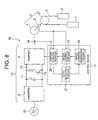
- Fig. 8 is a schematic diagram showing an elevator device according to Embodiment 3 of the present invention.
- the control means 17 has a duty detecting portion 21 in addition to the speed command generating portion 18, the speed control portion 19, and the current control portion 20.
- the duty detecting portion 21 Based on a voltage command value for the inverter 9, which is generated in the current control portion 20, the duty detecting portion 21 detects a switching duty as a load on the inverter 9.
- the switching duty is a ratio of a time period in which the inverter 9 is ON within a predetermined sampling period.
- the speed command generating portion 18 monitors whether or not the switching duty of the inverter 9, which has been detected by the duty detecting portion 21, reaches a preset threshold while the car 1 is running. Then, when the switching duty reaches the threshold, the speed command generating portion 18 imposes a speed limit.
- Embodiment 3 of the present invention is identical to Embodiment 1 or 2 of the present invention in other constructional details and other details about the method of control.
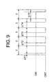
- Fig. 9 is an explanatory diagram showing an example of changes in the switching duty detected by the duty detecting portion 21 of Fig. 8 .
- a duty value Ti in a sampling period T is calculated as ⁇ Ti/T.
- the value of the switching duty gradually increases as the car 1 increases in speed after having started running ( ⁇ T1/T ⁇ ⁇ T2/T ⁇ ⁇ T3/T ⁇ ⁇ T4/T ⁇ ⁇ T5/T).
- the switching duty of the inverter 9 is monitored while the car 1 is running, and the speed command is generated without loss of time in accordance with the state of the switching duty and then output to the motor driving portion 15. It is therefore possible to operate the car 1 more efficiently while preventing at least one of the drive components from becoming overloaded.
- the product of the switching duty and the bus voltage (voltage input to inverter 9) is equal to the voltage of the motor 4. Accordingly, when the amplitude of fluctuations in bus voltage is low, voltage saturation of the motor 4 can be avoided beforehand by monitoring the switching duty.
- the threshold in accordance with the acceleration of the car 1 or the acceleration transition pattern of the car 1 such that the switching duty does not exceed the permissible value.
- the threshold is also appropriate to reset the threshold every time the car 1 runs. Still further, it is also appropriate to switch over the threshold depending on whether or not the motor 4 is in power running operation or regenerative operation. For example, when there is a thermal surplus in the regenerative resistor 12, the values of maximum speed and drive torque can be made higher during regenerative operation than during power running operation. As a result, it is possible to perform the operation of the car 1 more efficiently.
- a motor voltage is monitored as a load on at least one of the components of the drive means 16.
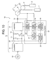
- Fig. 10 is a schematic diagram showing an elevator device according to Embodiment 4 of the present invention.
- a bus voltage detector 22 for detecting a bus voltage (DC voltage) smoothed by the smoothing capacitor 11 is provided between the converter 8 and the inverter 9.
- the control means 17 has a voltage calculating portion 23 in addition to the speed command generating portion 18, the speed control portion 19, the current control portion 20, and the duty detecting portion 21.
- the voltage calculating portion 23 calculates a voltage applied to the motor 4 from a bus voltage detected based on a signal from the bus voltage detector 22 and a switching duty detected by the duty detecting portion 21.
- the speed command generating portion 18 determines whether or not a motor voltage calculated by the voltage calculating portion 23 reaches a preset threshold while the car 1 is running. Then, when the motor voltage reaches the threshold, the speed command generating portion 18 imposes a speed limit.
- Embodiment 4 of the present invention is identical to Embodiment 3 of the present invention in other constructional details and other details about the method of control.
- the voltage applied to the motor 4 can be calculated accurately even when the bus voltage fluctuates due to fluctuations in the voltage of the power supply 10. It is therefore possible to more reliably prevent the motor 4 from becoming overloaded.
- a motor voltage is monitored as a load on at least one of the components of the drive means 16.
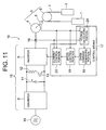
- Fig. 11 is a schematic diagram showing an elevator device according to Embodiment 5 of the present invention.
- the control means 17 has a voltage calculating portion 24 in addition to the speed command generating portion 18, the speed control portion 19, and the current control portion 20.
- the voltage calculating portion 24 calculates a voltage applied to the motor 4 based on a signal from the speed detector 6 and a signal from the current detector 14.
- a motor voltage can be obtained through calculation from a current value, a rotational speed, and positions of magnetic poles.
- the speed command generating portion 18 determines whether or not the motor voltage calculated by the voltage calculating portion 24 reaches a preset threshold while the car 1 is running. When the motor voltage reaches the threshold, the speed command generating portion 18 imposes a speed limit.
- Embodiment 5 of the present invention is identical to Embodiment 1 or 2 of the present invention in other constructional details and other details about the method of control.
- the motor voltage is monitored while the car 1 is running, and a speed command is generated without loss of time in accordance with a state of the motor voltage and then output to the motor driving portion 15. It is therefore possible to operate the car 1 more efficiently while preventing at least one of the drive components from becoming overloaded.
- the motor voltage increases depending mainly on the rotational speed of the motor 4.
- the motor 4 cannot be operated at such a speed that the motor voltage exceeds a voltage value allowed to be output from the inverter 9. Therefore, a deterioration in speed control or electromagnetic noise resulting from current distortion is caused when the motor voltage reaches an upper limit of the voltage allowed to be output from the inverter 9.
- a threshold of the motor voltage is set based on a maximum value of the voltage allowed to be output from the inverter 9.
- the speed command generating portion 18 outputs an acceleration transition command value to make a shift to constant-speed running.
- the speed command generating portion 18 calculates a deceleration command value at a deceleration start position to stop the car 1 .
- the motor voltage increases temporarily between a time point corresponding to the start of acceleration transition and a time point corresponding to the start of constant-speed running.
- the threshold is set such that the motor voltage does not exceed a permissible value.
- a load on at least one of the components of the drive means 16 is indirectly monitored from a difference between a current command value and a current measurement value.
- Fig. 12 is a schematic diagram showing an elevator device according to Embodiment 6 of the present invention. Referring to Fig. 12 , the speed command generating portion 18 compares a current command value generated by the current control portion 20 with a current measurement value measured based on a signal from the current detector 14 to estimate a load on at least one of the drive components.
- the speed command generating portion 18 monitors at least one of a difference between the current command value and the current measurement value and a derivative value of the difference between the current command value and the current measurement value, and imposes a speed limit when the monitored value reaches a threshold.
- Embodiment 6 of the present invention is identical to Embodiment 1 or 2 of the present invention in other constructional details and other details about the method of control.
- the motor 4 can be prevented from becoming overloaded by monitoring at least one of the difference between the current command value and the current measurement value and the derivative value of the difference between the current command value and the currentmeasurementvalue.
- the car 1 can be operated more efficiently by performing the monitoring operation described above, generating a speed command without loss of time, and outputting the speed command to the motor driving portion 15 while the car 1 is running.
- a load on at least one of the components of the drive means 16 is indirectly monitored from a difference between a speed command value and a speed measurement value.
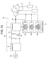
- Fig. 13 is a schematic diagram showing an elevator device according to Embodiment 7 of the present invention. Referring to Fig. 13 , the speed command generating portion 18 compares a speed command value generated by the speed command generating portion 18 with a speed measurement value measured based on a signal from the speed detector 6 to estimate a load on at least one of the drive components.
- the speed command generating portion 18 monitors at least one of a difference between the speed command value and the speed measurement value and a derivative value of the difference between the speed command value and the speed measurement value, and imposes a speed limit when the monitored value reaches a threshold.
- Embodiment 7 of the present invention is identical to Embodiment 1 or 2 of the present invention in other constructional details and other details about the method of control.
- the motor 4 can be prevented from becoming overloaded by monitoring at least one of the difference between the speed command value and the speed measurement value and the derivative value of the difference between the speed command value and the speed measurement value.
- the car 1 can be operated more efficiently by performing the monitoring operation described above, generating a speed command without loss of time, and outputting the speed command to the motor driving portion 15 while the car 1 is running.
- a regenerative power of the regenerative resistor 12 is monitored as a load on at least one of the components of the drive means 16.
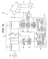
- Fig. 14 is a schematic diagram showing an elevator device according to Embodiment 8 of the present invention.
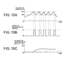
- Fig. 15 shows graphs of changes with time in the voltage of the smoothing capacitor 11 of Fig. 14 , in the ON/OFF state of the regenerative switch 13 of Fig. 14 , and in the ON ratio of the regenerative switch 13, respectively.
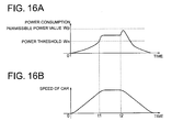
- Fig. 16 shows graphs of changes with time in the power consumption of the regenerative resistor 12 of Fig. 14 and the speed of the car 1, respectively.
- the DC voltage of the smoothing capacitor 11 is detected by a voltage detector 30.
- the turning ON/OFF of the regenerative switch 13 is controlled by a switch command portion 32.
- the switch command portion 32 generates an ON command signal for turning the regenerative switch 13 ON when the DC voltage detected by the voltage detector 30 becomes higher than a preset voltage threshold Von, and generates an OFF command signal for turning the regenerative switch 13 OFF when the DC voltage detected by the voltage detector 30 becomes lower than a voltage threshold Voff.
- a power consumption calculating portion 34 calculates a power consumption of the regenerative resistor 12 based on the ON command signal and the OFF command signal from the switch command portion 32. On the assumption that the ON command signal and the OFF command signal from the switch command portion 32 represent an ON state corresponding to 100% and an OFF state corresponding to 0%, respectively, the power consumption calculating portion 34 obtains an output signal indicating the ratio of the ON state of the regenerative switch 13, which has been smoothed as shown in Fig. 15 (c) .
- the power consumption calculating portion 34 has a first-order filter (filter means) 34a for a first-order delay having a suitable cutoff frequency, and a multiplier 34c.
- a power consumption power consumption-related value
- Von 2 /R denotes an instantaneous power consumption as a power consumed by the regenerative resistor 12
- R denotes an electric resistance value of the regenerative resistor 12.
- a comparison portion 35 has a comparator 35a and a reference 35c.
- a power threshold Wn can be set in the reference 35c.
- the comparator 35a compares the power consumption calculated by the multiplier 34c with the power threshold Wn preset in the reference 35c, and inputs a command change signal to the speed command generating portion 18 when the power consumption reaches the power threshold Wn.
- the power threshold Wn is set based on a permissible power value Wp for preventing the regenerative resistor 12 from becoming overloaded. More specifically, as shown in Fig. 16 , the power threshold Wn is set in consideration of a regenerative power consumption increasing between the time point t1 corresponding to the start of acceleration transition and a time point corresponding to the start of constant-speed running and a regenerative power consumption increasing temporarily from the time point t2 corresponding to the start of deceleration such that the regenerative power consumption does not exceed the permissible power value Wp.
- a resistor having a capacity permitting instantaneous consumption of a power corresponding to up to 100% of the ON ratio of the regenerative switch 13 is selected as the regenerative resistor 12.
- the regenerative power consumption is set equal to or lower than a rated power during continuous use of the regenerative resistor 12.
- the speed command generating portion 18 continues to generate a speed command value for continuing predetermined acceleration until a command change signal is input thereto. After the command change signal has been input to the speed command generating portion 18, the speed command generating portion 18 generates a speed command signal for causing the car 1 to start running at a constant speed when the car 1 is being accelerated, and generates a speed command signal for decelerating and stopping the car 1 when the car 1 is running at the constant speed to approach a stop position.
- the rotational speed of the motor 4 is calculated by differentiating a signal from the speed detector (rotational position detector) 6 using a differentiator 37 or the like.
- the control means 17 in Embodiment 8 of the present invention has the speed command generating portion 18, the speed control portion 19, the current control portion 20, the power consumption calculating portion 34, the comparison portion 35, and the differentiator 37.
- the motor 4 When the car 1 is being lowered with the load of the car 1 larger than the load of the counterweight 2, the motor 4 is in a regenerative state. In the regenerative state, a current flows from the motor 4 toward the inverter 9, so the smoothing capacitor 11 is charged. When the voltage of the smoothing capacitor 11 reaches the voltage threshold Von as a result of the charging thereof, an ON command signal is input from the switch command portion 32 to the regenerative switch 13.
- the first-order filter 34a of the power consumption calculating portion 34 smoothes a pulse-shaped ON/OFF command signal from the switch command portion 32 as shown in Fig. 15(c) and outputs the ON/OFF command signal as a smoothed signal.
- the smoothed signal indicates the ratio of an ON time period, namely, a time period in which the ON command signal constituting the ON/OFF command signal for the regenerative switch 13 is generated.
- An average power consumption of the regenerative resistor 12 can thereby be estimated. Accordingly, an average power consumption value can be calculated by multiplying the smoothed signal by the coefficient Von 2 /R in the multiplier 34c.
- the comparator 35a compares the power consumption with the power threshold Wn, and inputs a command change signal to the speed command generating portion 18 when the power consumption exceeds the power threshold Wn. As shown in Fig. 16 (a) , the power consumption gradually increases as the car 1 increases in speed after having started running. Then, the power consumption reaches the power threshold Wn at the time point t1 when the car 1 is running with accelerating speed.
- the comparator 35a When the power consumption exceeds the power threshold Wn, the comparator 35a outputs a command change signal to the speed command generating portion 18.
- the speed command generating portion 18 When the command change signal is input to the speed command generating portion 18, the speed command generating portion 18 generates a speed command to stop the car 1 from being accelerated if the car 1 is being accelerated, and to make a shift to constant-speed running, and outputs the speed command to the speed control portion 19. In this case, it is preferable to make a shift from the state of acceleration to the state of constant speed along a smooth curve in consideration of riding comfort of passengers.
- Embodiment 8 of the present invention is identical to Embodiment 1 or 2 of the present invention in other constructional details and other details about the method of control.
- the power consumption of the regenerative resistor 12 is monitored while the car 1 is running, and the control command regarding the running speed of the car 1 is generated in accordance with the state of the power consumption and then output to the motor driving portion 15. It is therefore possible to operate the car 1 more efficiently while preventing at least one of the drive components from becoming overloaded.
- the first-order filter 34a is employed to calculate the ratio of the ON time period of the regenerative switch 13 in Embodiment 8 of the present invention
- a high-order filter may be employed to perform the calculation. It is also appropriate to detect an ON time period and an OFF time period of the regenerative switch 13 within a preset time period to calculate the ratio of the ON time period. It is also appropriate to omit the multiplier 34c and input an output from the first-order filter 34a directly to the comparison portion 35.
- the current flowing when the regenerative switch 13 is turned ON is approximated as Von/R in Embodiment 8 of the present invention.
- the current is also appropriate to approximate the current as, for example, Voff/R or (Von + Voff)/R/2 on the assumption that a predetermined voltage between an ON start voltage Von and an OFF start voltage Voff is applied to the regenerative resistor 12.
- the amount of the increase in regenerative power increases notably when the car 1 makes a shift from accelerated running to constant-speed running and when the car 1 makes a shift from constant-speed running to decelerated running. It is therefore appropriate to set the power threshold Wn in consideration of the amount of the increase in regenerative power. That is, it is appropriate to obtain the power threshold Wn by subtracting the amount of the increase in regenerative power from a permissible power allowed to be regenerated through the regenerative resistor 12.
- the amount of the increase in regenerative power depends on the acceleration/deceleration of the car 1.
- the acceleration/deceleration of the car 1 depends on the motor torque generated by the motor 4.
- the motor torque can be calculated through conversion from the current of the motor 4. It is therefore appropriate to calculate the power threshold Wn in accordance with at least one of the acceleration/deceleration, the torque, and the current.
- the regenerative power increasing between the time point corresponding to the start of acceleration transition and the time point corresponding to the start of constant-speed running depends also on the acceleration transition pattern in a shift to constant-speed running. That is, the amount of the increase in regenerative power increases as the time period for acceleration transition is lengthened.
- the regenerative power increasing temporarily at the time point corresponding to the start of deceleration depends on the deceleration transition pattern in a shift to decelerated running. That is, the amount of the increase in regenerative power increases as the time period for deceleration transition is shortened. It is therefore appropriate to set the power threshold Wn in accordance with the acceleration (deceleration) transition pattern such that the regenerative power does not exceed the permissible value Wp.
- the acceleration (deceleration) transition pattern in accordance with the power threshold Wn such that the regenerative power does not exceed the permissible value Wp.
- the speed at which the car 1 is operated can be increased as the power threshold Wn is increased.
- the power threshold Wn it becomes more difficult to increase the deceleration of the car 1, and the time period for deceleration transition needs to be lengthened.
- the power threshold Wn it is preferable to set the power threshold Wn, the deceleration of the car 1, and the deceleration transition pattern of the car 1 such that the running time of the car 1 is reduced to the shortest possible time.
- a heat release amount or a temperature of the regenerative resistor 12 is monitored as a load on at least one of the components of the drive means 16.
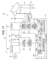
- Fig. 17 is a schematic diagram showing an elevator device according to Embodiment 9 of the present invention.
- a heat release amount calculating portion 134 has the first-order filter 34a, the multiplier 34c, and an integrator 34e.
- the integrator 34e calculates an estimated value of the heat release amount of the regenerative resistor 12 from a value obtained by integrating (accumulating) a power consumption obtained from the multiplier 34c over time.
- a threshold of a heat release amount (temperature threshold) can be set in the reference 35c.
- the comparator 35a compares the estimated value of the heat release amount calculated by the integrator 34e with the threshold of the heat release amount preset in the reference 35c, and inputs a command change signal to the speed command generating portion 18 when the estimated value of the heat release amount reaches the threshold of the heat release amount.
- the threshold of the heat release amount is set based on a permissible temperature for preventing the regenerative resistor 12 from becoming overloaded.
- Embodiment 9 of the present invention is identical to Embodiment 8 of the present invention in other constructional details.
- the heat release amount of the regenerative resistor 12 is monitored while the car 1 is running, and the control command regarding the running speed of the car 1 is generated in accordance with the heat release amount and then output to the motor driving portion 15. It is therefore possible to operate the car 1 more efficiently while preventing at least one of the drive components from becoming overloaded.
- Embodiment 10 of the present invention will be described.
- the heat release amount of the regenerative resistor 12 is monitored as a load on at least one of the components of the drive means 16.
- the threshold of the heat release amount is varied in accordance with the power consumption of the regenerative resistor 12.
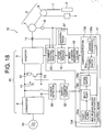
- Fig. 18 is a schematic diagram showing an elevator device according to Embodiment 10 of the present invention.
- a comparison portion 135 has the comparator 35a and a variable reference 135c.
- the variable reference 135c calculates a power consumption of the regenerative resistor 12 per predetermined time based on information from the multiplier 34c, and changes the threshold of the heat release amount in accordance with a result of the calculation.
- Fig. 19 is a graph showing an example of a method of setting a threshold of a heat release amount in the variable reference 135c of Fig. 18 . As shown in Fig. 19 , the threshold of the heat release amount is reduced as the power consumption of the regenerative resistor 12 per predetermined time increases.
- Embodiment 10 of the present invention is identical to Embodiment 9 of the present invention in other constructional details and other details about the method of control.
- the threshold of the heat release amount is shifted in accordance with the power consumption of the regenerative resistor 12 per predetermined time. It is therefore possible to more reliably prevent the regenerative resistor 12 from becoming overloaded by suitably changing the threshold of the heat release amount in accordance with the operating frequency of the car 1. For example, when the operating frequency of the car 1 becomes high, the power consumption of the regenerative resistor 12 per predetermined time increases, so the heat release amount rises abruptly. As a measure against this phenomenon, the threshold of the heat release amount is reduced to some extent. It is therefore possible to prevent the regenerative resistor 12 from becoming overloaded due to a control delay.
- the average power consumption can be calculated as a value obtained by multiplying an output from the first-order filter 34a by Von 2 /R.
- a motor voltage and a motor current are monitored as loads on at least one of the components of the drive means 16.
- Fig. 20 is composed of graphs showing a method of controlling the speed of the car 1 in an elevator device according to Embodiment 11 of the present invention. These graphs illustrate an example in which flux weakening control of the motor 4 is performed.
- the overall construction of the device is identical to that of Embodiment 5 of the present invention ( Fig. 11 ).
- Flux weakening control is a method of controlling the motor 4 such that a negative d-axis current is caused to flow through the motor 4 to suppress a rise in the voltage thereof and hence allow the motor 4 to rotate at high speed.
- flux weakening control when the voltage of the motor 4 rises due to acceleration of the car 1 after the car 1 has started running, flux weakening control is performed to cause the d-axis current to start flowing such that the voltage of the motor 4 does not exceed a threshold A3.
- the motor voltage is fixed to the threshold A3 at a time point t5. That is, flux weakening control is started at the time point t5 such that no more than a required amount of the d-axis current is caused to flow.
- the value of the motor voltage is held equal to or lower than the threshold A3 through flux weakening control.
- the d-axis current for suppressing an increase in the voltage of the motor 4 increases as well, so the motor current increases.
- the motor current is also monitored in Embodiment 11 of the present invention.
- the value of the motor current exceeds a threshold A4, it is determined that the car 1 is running at a critical speed permitting flux weakening control.
- a speed command is shifted to a speed command value for constant-speed running.
- the threshold A4 is set based on a permissible current B4 of the motor 4 or the inverter 9.
- the motor current increases temporarily between a time point t6 corresponding to the start of acceleration transition and a time point corresponding to the start of constant-speed running. In this case as well, however, the threshold A4 is set such that the motor current does not exceed the permissible value B4.
- the value of the motor current exceeds the threshold A4 after the value of the motor voltage has become constant through flux weakening control.
- the value of the motor voltage exceeds the threshold A3 before the value of the motor current exceeds the threshold A4 in the case where, for example, flux weakening control is not performed, a shift to constant-speed running is made immediately.
- Embodiment 11 of the present invention even when the voltage allowed to be output from the inverter 9 fluctuates, for example, when the voltage of the power supply 10 drops, in accordance with the fluctuation in the voltage of the power supply 10, a speed command value can be increased suitably within a range allowing the inverter 9 to output the voltage.
Landscapes
- Engineering & Computer Science (AREA)
- Automation & Control Theory (AREA)
- Elevator Control (AREA)
- Control Of Ac Motors In General (AREA)
Applications Claiming Priority (2)
| Application Number | Priority Date | Filing Date | Title |
|---|---|---|---|
| PCT/JP2005/013640 WO2007013141A1 (fr) | 2005-07-26 | 2005-07-26 | Dispositif de commande d’un élévateur-transporteur |
| PCT/JP2006/314667 WO2007013448A1 (fr) | 2005-07-26 | 2006-07-25 | Ascenseur |
Publications (3)
| Publication Number | Publication Date |
|---|---|
| EP1908719A1 true EP1908719A1 (fr) | 2008-04-09 |
| EP1908719A4 EP1908719A4 (fr) | 2013-01-16 |
| EP1908719B1 EP1908719B1 (fr) | 2018-04-04 |
Family
ID=37683049
Family Applications (1)
| Application Number | Title | Priority Date | Filing Date |
|---|---|---|---|
| EP06781579.5A Ceased EP1908719B1 (fr) | 2005-07-26 | 2006-07-25 | Ascenseur |
Country Status (5)
| Country | Link |
|---|---|
| US (1) | US7931128B2 (fr) |
| EP (1) | EP1908719B1 (fr) |
| KR (1) | KR100947695B1 (fr) |
| CN (1) | CN101068736B (fr) |
| WO (2) | WO2007013141A1 (fr) |
Cited By (2)
| Publication number | Priority date | Publication date | Assignee | Title |
|---|---|---|---|---|
| EP1918237A4 (fr) * | 2005-08-25 | 2013-03-13 | Mitsubishi Electric Corp | Dispositif de commande de fonctionnement d'élévateur |
| US9114955B2 (en) | 2010-03-03 | 2015-08-25 | Mitsubishi Electric Corporation | Control device for elevator |
Families Citing this family (39)
| Publication number | Priority date | Publication date | Assignee | Title |
|---|---|---|---|---|
| EP1950164B1 (fr) * | 2005-11-14 | 2018-01-24 | Mitsubishi Denki Kabushiki Kaisha | Dispositif de commande d ascenseur |
| JP2009519878A (ja) * | 2005-12-20 | 2009-05-21 | オーチス エレベータ カンパニー | エレベータ駆動装置制御方法 |
| EP2006232B1 (fr) | 2006-04-13 | 2019-01-23 | Mitsubishi Electric Corporation | Dispositif élévateur |
| JP4955556B2 (ja) * | 2006-07-27 | 2012-06-20 | 三菱電機株式会社 | エレベータ装置 |
| KR101115918B1 (ko) | 2007-02-14 | 2012-02-13 | 미쓰비시덴키 가부시키가이샤 | 엘리베이터 장치 |
| WO2008114294A1 (fr) * | 2007-03-22 | 2008-09-25 | Carraro S.R.L. | Vêtement anti-électrocution |
| JP4987074B2 (ja) | 2007-04-26 | 2012-07-25 | 三菱電機株式会社 | エレベータ装置 |
| CN101682280B (zh) * | 2007-06-14 | 2012-05-23 | 松下电器产业株式会社 | 电动机驱动装置、电动机装置和集成电路装置 |
| CA2698781C (fr) * | 2007-09-11 | 2013-07-09 | New York Air Brake Corporation | Unite d'affichage sans fil pour un systeme a transition electropneumatique |
| FI120070B (fi) * | 2007-10-01 | 2009-06-15 | Kone Corp | Sähkökäytön annon rajoittaminen sekä hissin suojaus |
| WO2009078088A1 (fr) * | 2007-12-17 | 2009-06-25 | Mitsubishi Electric Corporation | Dispositif élévateur |
| FI120193B (fi) * | 2008-01-09 | 2009-07-31 | Kone Corp | Hissijärjestelmän liikkeenohjaus |
| CN101925528B (zh) * | 2008-03-27 | 2012-11-28 | 三菱电机株式会社 | 电梯控制系统 |
| US8365872B2 (en) * | 2008-04-15 | 2013-02-05 | Mitsubishi Electric Corporation | Elevator device having the plurality of hoisting machines |
| EP2315349B1 (fr) * | 2008-08-05 | 2016-05-04 | Edwards Japan Limited | Circuit d'entraînement de moteur et pompe à vide équipée du circuit d'entraînement de moteur |
| CN101753097A (zh) * | 2008-12-03 | 2010-06-23 | 鸿富锦精密工业(深圳)有限公司 | 马达驱动装置 |
| TWI410039B (zh) * | 2008-12-12 | 2013-09-21 | Foxnum Technology Co Ltd | 馬達驅動裝置 |
| JP2010143692A (ja) * | 2008-12-17 | 2010-07-01 | Mitsubishi Electric Corp | エレベータ装置 |
| WO2010103643A1 (fr) * | 2009-03-12 | 2010-09-16 | 三菱電機株式会社 | Equipement d'élévateur |
| CA2779870C (fr) * | 2009-12-18 | 2014-10-21 | Mitsubishi Electric Corporation | Appareil de commande d'entrainement de vehicule electrique |
| CN102198900B (zh) * | 2010-03-23 | 2013-06-12 | 上海三菱电梯有限公司 | 能量回馈电梯后备电源运行控制系统 |
| FI122125B (fi) * | 2010-04-07 | 2011-08-31 | Kone Corp | Säätölaite ja hissin sähkökäyttö |
| WO2011158357A1 (fr) * | 2010-06-17 | 2011-12-22 | 三菱電機株式会社 | Appareil de commande d'ascenseur |
| EP2503666A3 (fr) * | 2011-02-01 | 2013-04-17 | Siemens Aktiengesellschaft | Système d'alimentation pour commande électrique d'un navire |
| JP5753770B2 (ja) * | 2011-03-30 | 2015-07-22 | 株式会社日立産機システム | 電力変換装置 |
| JP5638043B2 (ja) * | 2012-09-07 | 2014-12-10 | ファナック株式会社 | アラームレベル設定部を有するモータ駆動装置 |
| EP2865629B1 (fr) * | 2013-10-24 | 2016-11-30 | Kone Corporation | Détection d'une condition de décrochage |
| CN104210911B (zh) * | 2014-08-22 | 2016-09-14 | 上海吉亿电机有限公司 | 一种可关断式电梯电源以及实现方法 |
| US10532908B2 (en) | 2015-12-04 | 2020-01-14 | Otis Elevator Company | Thrust and moment control system for controlling linear motor alignment in an elevator system |
| DE102016004062B4 (de) * | 2016-04-08 | 2026-01-22 | Sew-Eurodrive Gmbh & Co Kg | Antrieb, aufweisend einen von einem Umrichter gespeisten Elektromotor, und Verfahren zum Betreiben eines Antriebs |
| US10873270B2 (en) * | 2017-03-23 | 2020-12-22 | Eaton Intelligent Power Limited | Converter apparatus using source-activated discharge circuits |
| WO2019073527A1 (fr) * | 2017-10-10 | 2019-04-18 | 三菱電機株式会社 | Dispositif de commande d'ascenseur et procédé de commande |
| CN108249237A (zh) * | 2017-11-30 | 2018-07-06 | 上海贝思特电气有限公司 | 一种实现电梯在电压不足时自动降速运行的算法 |
| DE112018008058T5 (de) * | 2018-10-03 | 2021-06-17 | Mitsubishi Electric Corporation | Aufzugssteuervorrichtung |
| CN111813198B (zh) * | 2019-04-12 | 2022-11-22 | 阿里巴巴集团控股有限公司 | 数据处理方法、装置、电子设备及可读存储介质 |
| EP3733578A1 (fr) * | 2019-05-03 | 2020-11-04 | Otis Elevator Company | Entraînement régénératif |
| CN112390198B (zh) * | 2019-09-25 | 2022-01-18 | 河南嘉晨智能控制股份有限公司 | 车辆安全作业中起升电流的筛选方法 |
| CN111224588B (zh) * | 2020-01-07 | 2023-06-27 | 深圳市显控科技股份有限公司 | 伺服驱动器再生控制方法、系统、设备及存储介质 |
| CN113942903B (zh) * | 2021-11-04 | 2023-08-11 | 上海辛格林纳新时达电机有限公司 | 一种电梯的控制方法以及电梯 |
Family Cites Families (43)
| Publication number | Priority date | Publication date | Assignee | Title |
|---|---|---|---|---|
| JPS5842573A (ja) | 1981-09-04 | 1983-03-12 | 株式会社日立製作所 | エレベ−タ−の制御装置 |
| JPS58144076A (ja) | 1982-02-17 | 1983-08-27 | 株式会社日立製作所 | エレベ−タ−の制御装置 |
| JPS6118512A (ja) | 1984-07-04 | 1986-01-27 | Nissan Motor Co Ltd | 車両用サスペンシヨン制御装置 |
| JPS61162477A (ja) * | 1985-01-09 | 1986-07-23 | 三菱電機株式会社 | 交流エレベ−タの制御装置 |
| JPS6223708A (ja) | 1985-07-25 | 1987-01-31 | 松下電工株式会社 | 建築用板の成形方法 |
| JPS6274890A (ja) | 1985-09-30 | 1987-04-06 | 株式会社東芝 | エレベ−タの制御装置 |
| JPS6279182A (ja) | 1985-09-30 | 1987-04-11 | 株式会社東芝 | エレベ−タの制御装置 |
| JPH01185182A (ja) * | 1988-01-12 | 1989-07-24 | Toshiba Corp | インバータ装置 |
| JPH0657807B2 (ja) | 1988-07-20 | 1994-08-03 | トヨタ自動車株式会社 | 顔料及びその製造方法 |
| JP2567053B2 (ja) | 1988-09-01 | 1996-12-25 | 株式会社東芝 | エレベータ制御装置 |
| JPH02214486A (ja) | 1989-02-13 | 1990-08-27 | Mitsubishi Electric Corp | エレベータの制御装置 |
| AU640998B2 (en) | 1990-04-12 | 1993-09-09 | Otis Elevator Company | Elevator motion profile selection |
| JPH0526968A (ja) * | 1991-07-19 | 1993-02-05 | Hitachi Ltd | インサーキツトテスタのフイクスチヤ設計方法 |
| JP2505704Y2 (ja) * | 1991-09-18 | 1996-07-31 | フジテック株式会社 | 交流エレベ―タの制御装置 |
| JPH05306074A (ja) | 1992-05-06 | 1993-11-19 | Mitsubishi Electric Corp | エレベータの制御装置 |
| JPH06141539A (ja) * | 1992-10-21 | 1994-05-20 | Matsushita Electric Ind Co Ltd | スイッチング電源装置 |
| JP2889950B2 (ja) | 1993-12-02 | 1999-05-10 | 村田機械株式会社 | モータ駆動装置 |
| JPH07291542A (ja) * | 1994-04-28 | 1995-11-07 | Nippon Otis Elevator Co | エレベータ用インバータの速度制御装置 |
| JP3140308B2 (ja) | 1994-10-05 | 2001-03-05 | シャープ株式会社 | 昇圧型チョッパレギュレータ |
| KR960039576A (ko) * | 1995-04-28 | 1996-11-25 | 이나바 세이우에몬 | 서보 모터용 인버터의 회생 저항 보호 방법 및 보호 장치 |
| JPH092753A (ja) | 1995-06-21 | 1997-01-07 | Hitachi Ltd | エレベーターの制御装置 |
| EP0767133B1 (fr) * | 1995-10-05 | 2002-07-31 | Otis Elevator Company | Détecteur de malfonction pour entraínement d'ascenseur |
| JPH09233898A (ja) * | 1996-02-28 | 1997-09-05 | Hitachi Ltd | 交流電動機の制御装置及びエレベータの制御装置 |
| GB2310770B (en) * | 1996-02-28 | 1998-02-04 | Hitachi Ltd | Control device for controlling AC motor such as that in elevator with high driving efficiency |
| US5777280A (en) * | 1996-08-27 | 1998-07-07 | Otis Elevator Company | Calibration routine with adaptive load compensation |
| JPH10164883A (ja) * | 1996-12-02 | 1998-06-19 | Fuji Electric Co Ltd | インバータ制御装置 |
| JPH11199148A (ja) * | 1998-01-14 | 1999-07-27 | Toshiba Corp | 昇降機制御装置 |
| KR100303011B1 (ko) * | 1998-12-12 | 2002-05-09 | 장병우 | 엘리베이터의운전제어장치 |
| SG87902A1 (en) * | 1999-10-01 | 2002-04-16 | Inventio Ag | Monitoring device for drive equipment for lifts |
| JP4283963B2 (ja) * | 2000-02-28 | 2009-06-24 | 三菱電機株式会社 | エレベータの制御装置 |
| JP2001240323A (ja) * | 2000-02-28 | 2001-09-04 | Mitsubishi Electric Corp | エレベーターの制御装置 |
| JP4343381B2 (ja) * | 2000-02-28 | 2009-10-14 | 三菱電機株式会社 | エレベーターの制御装置 |
| JP4249364B2 (ja) * | 2000-02-28 | 2009-04-02 | 三菱電機株式会社 | エレベータの制御装置 |
| JP2002003091A (ja) * | 2000-06-22 | 2002-01-09 | Toshiba Fa Syst Eng Corp | エレベーター制御システム |
| JP2002060147A (ja) | 2000-08-18 | 2002-02-26 | Mitsubishi Electric Corp | エレベーターの制御装置 |
| JPWO2002083543A1 (ja) * | 2001-04-10 | 2004-08-05 | 三菱電機株式会社 | エレベータのガイド装置 |
| DE50209017D1 (de) * | 2001-07-04 | 2007-02-01 | Inventio Ag | Verfahren zum verhindern einer unzulässig hohen fahrgeschwindigkeit des lastaufnahmemittels eines aufzugs |
| JP4158883B2 (ja) * | 2001-12-10 | 2008-10-01 | 三菱電機株式会社 | エレベータおよびその制御装置 |
| US6619434B1 (en) | 2002-03-28 | 2003-09-16 | Thyssen Elevator Capital Corp. | Method and apparatus for increasing the traffic handling performance of an elevator system |
| JP4098182B2 (ja) * | 2003-08-07 | 2008-06-11 | 株式会社日立製作所 | モータ駆動システム及びエレベータ駆動システム |
| CN1839084B (zh) | 2003-09-29 | 2010-10-06 | 三菱电机株式会社 | 电梯控制装置 |
| WO2006046295A1 (fr) * | 2004-10-28 | 2006-05-04 | Mitsubishi Denki Kabushiki Kaisha | Dispositif de commande pour une machine tournante destinee a un ascenseur |
| JP2006213447A (ja) | 2005-02-02 | 2006-08-17 | Hitachi Ltd | エレベーター装置 |
-
2005
- 2005-07-26 WO PCT/JP2005/013640 patent/WO2007013141A1/fr not_active Ceased
-
2006
- 2006-07-25 EP EP06781579.5A patent/EP1908719B1/fr not_active Ceased
- 2006-07-25 WO PCT/JP2006/314667 patent/WO2007013448A1/fr not_active Ceased
- 2006-07-25 KR KR1020077014555A patent/KR100947695B1/ko not_active Expired - Fee Related
- 2006-07-25 US US11/666,989 patent/US7931128B2/en not_active Expired - Fee Related
- 2006-07-25 CN CN2006800012816A patent/CN101068736B/zh not_active Expired - Fee Related
Cited By (2)
| Publication number | Priority date | Publication date | Assignee | Title |
|---|---|---|---|---|
| EP1918237A4 (fr) * | 2005-08-25 | 2013-03-13 | Mitsubishi Electric Corp | Dispositif de commande de fonctionnement d'élévateur |
| US9114955B2 (en) | 2010-03-03 | 2015-08-25 | Mitsubishi Electric Corporation | Control device for elevator |
Also Published As
| Publication number | Publication date |
|---|---|
| KR100947695B1 (ko) | 2010-03-16 |
| WO2007013141A1 (fr) | 2007-02-01 |
| US20070284196A1 (en) | 2007-12-13 |
| CN101068736B (zh) | 2010-11-03 |
| KR20070088740A (ko) | 2007-08-29 |
| US7931128B2 (en) | 2011-04-26 |
| EP1908719B1 (fr) | 2018-04-04 |
| EP1908719A4 (fr) | 2013-01-16 |
| WO2007013448A1 (fr) | 2007-02-01 |
| CN101068736A (zh) | 2007-11-07 |
Similar Documents
| Publication | Publication Date | Title |
|---|---|---|
| EP1908719B1 (fr) | Ascenseur | |
| EP2956395B1 (fr) | Commande de vitesse de cabine d'ascenseur dans un système d'ascenseur alimenté par batterie | |
| EP2019071B1 (fr) | Dispositif de commande pour ascenceur | |
| US8714313B2 (en) | Electrical power system with power limiting to network | |
| KR101115918B1 (ko) | 엘리베이터 장치 | |
| KR101189883B1 (ko) | 엘리베이터의 제어 시스템 | |
| EP1950164B1 (fr) | Dispositif de commande d ascenseur | |
| US8763760B2 (en) | Adjustment device for controlling electric drive of an elevator, electric drive of an elevator and method for controlling electric drive of an elevator | |
| JP4397721B2 (ja) | エレベータの制御装置 | |
| CN1902116B (zh) | 电梯控制装置 | |
| JP4864440B2 (ja) | エレベータ装置 | |
| JP2010143692A (ja) | エレベータ装置 | |
| JP4663849B2 (ja) | エレベータの制御装置 | |
| JP5095223B2 (ja) | エレベータ装置 | |
| JP2010168139A (ja) | エレベーター制御装置 | |
| KR100829319B1 (ko) | 엘리베이터 제어장치 | |
| JP2005324880A (ja) | エレベータ制御装置 | |
| HK1156014B (en) | Device of an method for speed control of elevator |
Legal Events
| Date | Code | Title | Description |
|---|---|---|---|
| PUAI | Public reference made under article 153(3) epc to a published international application that has entered the european phase |
Free format text: ORIGINAL CODE: 0009012 |
|
| 17P | Request for examination filed |
Effective date: 20070601 |
|
| AK | Designated contracting states |
Kind code of ref document: A1 Designated state(s): DE ES FR PT |
|
| DAX | Request for extension of the european patent (deleted) | ||
| RBV | Designated contracting states (corrected) |
Designated state(s): DE ES FR PT |
|
| A4 | Supplementary search report drawn up and despatched |
Effective date: 20121214 |
|
| RIC1 | Information provided on ipc code assigned before grant |
Ipc: B66B 1/30 20060101AFI20121210BHEP |
|
| GRAP | Despatch of communication of intention to grant a patent |
Free format text: ORIGINAL CODE: EPIDOSNIGR1 |
|
| INTG | Intention to grant announced |
Effective date: 20171207 |
|
| GRAS | Grant fee paid |
Free format text: ORIGINAL CODE: EPIDOSNIGR3 |
|
| GRAA | (expected) grant |
Free format text: ORIGINAL CODE: 0009210 |
|
| AK | Designated contracting states |
Kind code of ref document: B1 Designated state(s): DE ES FR PT |
|
| REG | Reference to a national code |
Ref country code: DE Ref legal event code: R096 Ref document number: 602006055075 Country of ref document: DE |
|
| PG25 | Lapsed in a contracting state [announced via postgrant information from national office to epo] |
Ref country code: ES Free format text: LAPSE BECAUSE OF FAILURE TO SUBMIT A TRANSLATION OF THE DESCRIPTION OR TO PAY THE FEE WITHIN THE PRESCRIBED TIME-LIMIT Effective date: 20180404 |
|
| PG25 | Lapsed in a contracting state [announced via postgrant information from national office to epo] |
Ref country code: PT Free format text: LAPSE BECAUSE OF FAILURE TO SUBMIT A TRANSLATION OF THE DESCRIPTION OR TO PAY THE FEE WITHIN THE PRESCRIBED TIME-LIMIT Effective date: 20180806 |
|
| REG | Reference to a national code |
Ref country code: DE Ref legal event code: R097 Ref document number: 602006055075 Country of ref document: DE |
|
| PLBE | No opposition filed within time limit |
Free format text: ORIGINAL CODE: 0009261 |
|
| STAA | Information on the status of an ep patent application or granted ep patent |
Free format text: STATUS: NO OPPOSITION FILED WITHIN TIME LIMIT |
|
| 26N | No opposition filed |
Effective date: 20190107 |
|
| PG25 | Lapsed in a contracting state [announced via postgrant information from national office to epo] |
Ref country code: FR Free format text: LAPSE BECAUSE OF NON-PAYMENT OF DUE FEES Effective date: 20180731 |
|
| PGFP | Annual fee paid to national office [announced via postgrant information from national office to epo] |
Ref country code: DE Payment date: 20200714 Year of fee payment: 15 |
|
| REG | Reference to a national code |
Ref country code: DE Ref legal event code: R084 Ref document number: 602006055075 Country of ref document: DE |
|
| REG | Reference to a national code |
Ref country code: DE Ref legal event code: R119 Ref document number: 602006055075 Country of ref document: DE |
|
| PG25 | Lapsed in a contracting state [announced via postgrant information from national office to epo] |
Ref country code: DE Free format text: LAPSE BECAUSE OF NON-PAYMENT OF DUE FEES Effective date: 20220201 |