EP1930645A1 - Conduite a zone de melange de liquides - Google Patents
Conduite a zone de melange de liquides Download PDFInfo
- Publication number
- EP1930645A1 EP1930645A1 EP06810749A EP06810749A EP1930645A1 EP 1930645 A1 EP1930645 A1 EP 1930645A1 EP 06810749 A EP06810749 A EP 06810749A EP 06810749 A EP06810749 A EP 06810749A EP 1930645 A1 EP1930645 A1 EP 1930645A1
- Authority
- EP
- European Patent Office
- Prior art keywords
- pipe
- fluid
- mixing region
- downstream
- end portion
- Prior art date
- Legal status (The legal status is an assumption and is not a legal conclusion. Google has not performed a legal analysis and makes no representation as to the accuracy of the status listed.)
- Withdrawn
Links
- 239000012530 fluid Substances 0.000 title claims abstract description 138
- 238000011144 upstream manufacturing Methods 0.000 claims description 34
- XLYOFNOQVPJJNP-UHFFFAOYSA-N water Substances O XLYOFNOQVPJJNP-UHFFFAOYSA-N 0.000 abstract description 112
- 239000003638 chemical reducing agent Substances 0.000 abstract description 80
- 230000004048 modification Effects 0.000 description 11
- 238000012986 modification Methods 0.000 description 11
- 230000002093 peripheral effect Effects 0.000 description 11
- 230000007423 decrease Effects 0.000 description 9
- 239000002184 metal Substances 0.000 description 7
- 229910052751 metal Inorganic materials 0.000 description 7
- 230000003247 decreasing effect Effects 0.000 description 3
- 238000000034 method Methods 0.000 description 3
- 230000001133 acceleration Effects 0.000 description 2
- 230000000694 effects Effects 0.000 description 2
- 238000009434 installation Methods 0.000 description 2
- 230000000717 retained effect Effects 0.000 description 2
- 230000008646 thermal stress Effects 0.000 description 2
- 238000003466 welding Methods 0.000 description 1
Images





Classifications
-
- F—MECHANICAL ENGINEERING; LIGHTING; HEATING; WEAPONS; BLASTING
- F16—ENGINEERING ELEMENTS AND UNITS; GENERAL MEASURES FOR PRODUCING AND MAINTAINING EFFECTIVE FUNCTIONING OF MACHINES OR INSTALLATIONS; THERMAL INSULATION IN GENERAL
- F16L—PIPES; JOINTS OR FITTINGS FOR PIPES; SUPPORTS FOR PIPES, CABLES OR PROTECTIVE TUBING; MEANS FOR THERMAL INSULATION IN GENERAL
- F16L55/00—Devices or appurtenances for use in, or in connection with, pipes or pipe systems
-
- B—PERFORMING OPERATIONS; TRANSPORTING
- B01—PHYSICAL OR CHEMICAL PROCESSES OR APPARATUS IN GENERAL
- B01F—MIXING, e.g. DISSOLVING, EMULSIFYING OR DISPERSING
- B01F25/00—Flow mixers; Mixers for falling materials, e.g. solid particles
- B01F25/30—Injector mixers
- B01F25/31—Injector mixers in conduits or tubes through which the main component flows
- B01F25/313—Injector mixers in conduits or tubes through which the main component flows wherein additional components are introduced in the centre of the conduit
-
- B—PERFORMING OPERATIONS; TRANSPORTING
- B01—PHYSICAL OR CHEMICAL PROCESSES OR APPARATUS IN GENERAL
- B01F—MIXING, e.g. DISSOLVING, EMULSIFYING OR DISPERSING
- B01F25/00—Flow mixers; Mixers for falling materials, e.g. solid particles
-
- B—PERFORMING OPERATIONS; TRANSPORTING
- B01—PHYSICAL OR CHEMICAL PROCESSES OR APPARATUS IN GENERAL
- B01F—MIXING, e.g. DISSOLVING, EMULSIFYING OR DISPERSING
- B01F25/00—Flow mixers; Mixers for falling materials, e.g. solid particles
- B01F25/20—Jet mixers, i.e. mixers using high-speed fluid streams
-
- F—MECHANICAL ENGINEERING; LIGHTING; HEATING; WEAPONS; BLASTING
- F17—STORING OR DISTRIBUTING GASES OR LIQUIDS
- F17D—PIPE-LINE SYSTEMS; PIPE-LINES
- F17D1/00—Pipe-line systems
- F17D1/08—Pipe-line systems for liquids or viscous products
- F17D1/16—Facilitating the conveyance of liquids or effecting the conveyance of viscous products by modification of their viscosity
- F17D1/17—Facilitating the conveyance of liquids or effecting the conveyance of viscous products by modification of their viscosity by mixing with another liquid, i.e. diluting
-
- B—PERFORMING OPERATIONS; TRANSPORTING
- B01—PHYSICAL OR CHEMICAL PROCESSES OR APPARATUS IN GENERAL
- B01F—MIXING, e.g. DISSOLVING, EMULSIFYING OR DISPERSING
- B01F25/00—Flow mixers; Mixers for falling materials, e.g. solid particles
- B01F2025/91—Direction of flow or arrangement of feed and discharge openings
- B01F2025/913—Vortex flow, i.e. flow spiraling in a tangential direction and moving in an axial direction
-
- Y—GENERAL TAGGING OF NEW TECHNOLOGICAL DEVELOPMENTS; GENERAL TAGGING OF CROSS-SECTIONAL TECHNOLOGIES SPANNING OVER SEVERAL SECTIONS OF THE IPC; TECHNICAL SUBJECTS COVERED BY FORMER USPC CROSS-REFERENCE ART COLLECTIONS [XRACs] AND DIGESTS
- Y02—TECHNOLOGIES OR APPLICATIONS FOR MITIGATION OR ADAPTATION AGAINST CLIMATE CHANGE
- Y02E—REDUCTION OF GREENHOUSE GAS [GHG] EMISSIONS, RELATED TO ENERGY GENERATION, TRANSMISSION OR DISTRIBUTION
- Y02E30/00—Energy generation of nuclear origin
Definitions
- the present invention relates to piping that has a fluid-mixing region where fluids of different temperatures are mixed and that is suitable for use in, for example, nuclear power plants.
- Much piping through which high-temperature water and low-temperature water flow is provided in plants such as nuclear power plants and thermal power plants.
- Such piping includes a branch pipe perpendicularly connected to a main pipe and has a fluid-mixing region where low-temperature water flowing through the branch pipe joins high-temperature water flowing through the main pipe (of course, a configuration in which low-temperature water flows through the main pipe and high-temperature water flows through the branch pipe is also possible).
- a temperature interface is formed between the high-temperature water and the low-temperature water. This temperature interface varies in position (temperature fluctuation), thus causing the problem that the metal constituting the piping experiences thermal fatigue. To avoid the thermal fatigue, the high-temperature water and the low-temperature water must be quickly mixed.
- Patent Document 1 discloses a technique for facilitating the mixing of high-temperature water flowing through a main pipe and low-temperature water flowing out of a reducer through a branch pipe by fixing an upstream end of the reducer to an inner circumferential wall of the branch pipe and positioning a downstream end of the reducer, having a reduced inner diameter, on the central axis of the main pipe.
- Patent Document 1 Japanese Unexamined Patent Application, Publication No. 2005-16686 ( Figs. 10 , 13 , and 14 )
- Patent Document 1 Although the technique described in Patent Document 1 facilitates the mixing of fluids, it is difficult to completely prevent variations in temperature interfaces occurring at various sites of the piping. A measure has therefore been demanded to further reduce thermal fatigue resulting from variations in temperature interfaces.
- An object of the present invention which has been made in light of the above circumstances, is to prevent thermal fatigue, resulting from variations in temperature interfaces, of piping having a fluid-mixing region where fluids of different temperatures are mixed.
- piping of the present invention having a fluid-mixing region employs the following solutions.
- piping having a fluid-mixing region includes a first pipe and an inner pipe including an end portion disposed in the first pipe substantially on a central axis of the first pipe.
- An inner fluid flows through the inner pipe at a lower velocity than an outer fluid flowing outside the end portion.
- the inner and outer fluids have different temperatures.
- the inner and outer fluids are mixed in the fluid-mixing region downstream of the inner pipe.
- the inner pipe has a weld formed to connect the end portion and a downstream portion together. The distance between the weld and a downstream end of the end portion is equal to or larger than the inner diameter of the first pipe.
- the outer fluid flows back into the inner pipe. If the outer fluid flowing back into the inner pipe reaches the vicinity of the weld of the inner pipe, it causes temperature fluctuations due to temperature variations at the weld, thus leading to thermal fatigue. This results in a decreased lifetime because the weld has a lower fatigue strength than the unwelded portion and thus easily suffers breakage.
- the distance between the weld and the downstream end of the end portion of the inner pipe is equal to or larger than the inner diameter of the first pipe. This prevents the backflow of the outer fluid from reaching the vicinity of the weld and thus prevents breakage due to thermal fatigue at the weld.
- Other piping of the present invention having a fluid-mixing region includes a first pipe and an inner pipe including an end portion disposed in the first pipe substantially on a central axis of the first pipe.
- An inner fluid flows through the inner pipe at a lower velocity than an outer fluid flowing outside the end portion.
- the inner and outer fluids have different temperatures.
- the inner and outer fluids are mixed in the fluid-mixing region downstream of the inner pipe.
- a small-diameter portion is provided at a downstream end of the end portion of the inner pipe and has a smaller inner diameter than the upstream side thereof.
- the small-diameter portion provided at the downstream end of the end portion of the inner pipe, further accelerates the inner fluid flowing through the inner pipe. This prevents the outer fluid from flowing back into the inner pipe.
- swirling part may be provided upstream of the downstream end of the inner pipe to apply a swirling force to the outer fluid about the central axis.
- Other piping of the present invention having a fluid-mixing region includes a first pipe and an inner pipe including an end portion disposed in the first pipe substantially on a central axis of the first pipe.
- An inner fluid flows through the inner pipe and has a temperature different from that of an outer fluid flowing outside the end portion.
- the inner and outer fluids are mixed in the fluid-mixing region downstream of the inner pipe.
- An inner cylinder is disposed in the inner pipe and has a downstream end positioned downstream of a downstream end of the inner pipe, and a gap is formed between the inner cylinder and an inner wall of the inner pipe.
- the inner cylinder is disposed in the inner pipe with the gap formed between the inner wall of the inner pipe and the inner cylinder.
- the inner fluid is split into a peripheral flow between the outside of the inner cylinder and the inside of the inner pipe and a central flow through the inside of the inner cylinder.
- peripheral flow split from the central flow, forms a thin layer which facilitates the mixing with the outer fluid.
- the central flow split from the peripheral flow, emerges from the downstream end of the inner cylinder and forms a flow having a small cross-sectional area (i.e., a narrow flow) which facilitates the mixing with the outer fluid.
- downstream end of the inner cylinder is disposed downstream of the downstream end of the inner pipe, so that the mixing is performed in two steps: first, mixing the peripheral flow with the outer fluid, and second, mixing the central flow with the outer fluid. This further facilitates the mixing with the outer fluid.
- the above piping further includes a swirling part fixed between the inner circumferential wall of the inner pipe and an outer circumferential wall of the inner cylinder to apply a swirling force to the fluid about the central axis.
- the swirling part applies a swirling force to the peripheral portion of the inner fluid flowing between the outside of the inner cylinder and the inside of the inner pipe. This facilitates the mixing with the outer fluid.
- the inner cylinder can reliably be supported because the swirling part is provided between the inner circumferential wall of the inner pipe and the outer circumferential wall of the inner cylinder so as to hold the inner cylinder.
- Other piping of the present invention having a fluid-mixing region includes a first pipe and an inner pipe including an end portion disposed in the first pipe substantially on a central axis of the first pipe.
- An inner fluid flows through the inner pipe and has a temperature different from that of an outer fluid flowing outside the end portion.
- the inner and outer fluids are mixed in the fluid-mixing region downstream of the inner pipe.
- the first pipe includes a bent portion, and the inner pipe extends downstream of the bent portion.
- the bent portion is formed in the first pipe and the region where the inner and outer fluids are mixed is positioned upstream of the bent portion, the fluid that has not yet been sufficiently mixed may collide with the bent portion. In that case, the bent portion would experience temperature fluctuations which could cause thermal stress or thermal fatigue.
- the inner pipe extends downstream of the bent portion, and the fluid-mixing region is provided downstream of the bent portion. This prevents thermal fatigue at the bent portion.
- the above piping having the fluid-mixing region further includes a swirling part fixed between an inner circumferential wall of the first pipe and an outer circumferential wall of the inner pipe to apply a swirling force to the fluid about the central axis.
- the swirling part can apply a swirling force to the outer fluid flowing between the outside of the inner pipe and the inside of the first pipe. This facilitates the mixing.
- the inner pipe extends downstream of the bent portion; this may be disadvantageous in terms of the rigidity with which the inner pipe is supported.
- the rigidity with which the inner pipe is supported can be enhanced because the swirling part is provided between the inner circumferential wall of the first pipe and the outer circumferential wall of the inner pipe so as to hold the inner pipe.
- Other piping of the present invention having a fluid-mixing region includes a first pipe and an inner pipe including an end portion disposed in the first pipe substantially on a central axis of the first pipe.
- An inner fluid flows through the inner pipe at a lower velocity than an outer fluid flowing outside the end portion.
- the inner and outer fluids have different temperatures.
- the inner and outer fluids are mixed in the fluid-mixing region downstream of the inner pipe.
- the first pipe includes a wide portion having an increased inner diameter in the fluid-mixing region.
- the wide portion of the first pipe decreases the velocity of the outer fluid flowing through the first pipe to reduce the velocity difference between the outer fluid and the inner fluid, which has a lower velocity, thus lowering confluence resistance.
- the piping of the present invention having the fluid-mixing region further includes a swirling part provided in the wide portion of the first pipe to apply a swirling force to the outer fluid.
- the swirling part provided in the wide portion applies a swirling force to the outer fluid to facilitate the mixing with the inner fluid.
- Other piping of the present invention having a fluid-mixing region includes a first pipe and an inner pipe including an end portion disposed in the first pipe substantially on a central axis of the first pipe.
- An inner fluid flows through the inner pipe at a higher velocity than an outer fluid flowing outside the end portion.
- the inner and outer fluids have different temperatures.
- the inner and outer fluids are mixed in the fluid-mixing region downstream of the inner pipe.
- a wide pipe whose inner diameter increases gradually downstream is provided at an end of the inner pipe.
- the wide pipe is provided at the end of the inner pipe to decrease the velocity of the inner fluid. This reduces the velocity difference between the inner fluid and the outer fluid, which has a lower velocity, thus lowering confluence resistance.
- the inner pipe has intake part for taking in part of the unmixed fluid before the fluid reaches the fluid-mixing region.
- the inner pipe has the inlet for taking in part of the fluid (for example, the outer fluid or a fluid flowing from the upstream side of the first pipe) before the fluid reaches the fluid-mixing region.
- the unmixed fluid flowing into the inner pipe through the intake part is mixed with the inner fluid flowing through the inner pipe.
- the fluid thus mixed flows out of the end of the inner pipe and is mixed again with the outer fluid in the fluid-mixing region. This enables two-step mixing, thus reducing confluence resistance.
- the intake part used is, for example, an opening formed in the wall of the inner pipe or a bypass pipe joined to the wall of the inner pipe so as to face the upstream side.
- Each of the piping having the fluid-mixing region described above further includes a second pipe joined to the outer wall of the first pipe to guide the inner fluid, and an upstream end of the inner pipe is fixed to an inner circumferential wall of the second pipe.
- the fluid flowing through the second pipe enters the inner pipe, which guides the fluid and allows it to be mixed with the outer fluid flowing through the first pipe.
- the inner diameter of the inner pipe, joined to the inner circumferential wall of the second pipe, is smaller than that of the second pipe.
- the inner pipe thus functions as a reducer.
- each of the piping having the fluid-mixing region further includes a second pipe joined to the outer wall of the first pipe to guide the outer fluid, and the upstream end of the inner pipe is fixed to the inner circumferential wall of the first pipe.
- the fluid flowing through the first pipe enters the inner pipe, which guides the fluid and allows it to be mixed with the outer fluid flowing from the second pipe into the first pipe.
- the inner diameter of the inner pipe, joined to the inner circumferential wall of the first pipe, is smaller than that of the first pipe.
- the inner pipe thus functions as a reducer.
- the distance between the weld and the downstream end of the inner pipe can be appropriately determined so as not to cause temperature variations near the weld, thus preventing thermal fatigue at the weld, where the fatigue strength is low.
- the small-diameter portion can be provided at the downstream end of the inner pipe to facilitate the mixing of the fluids, thus reducing temperature variations and preventing thermal fatigue.
- the inner cylinder can be provided at the end of the inner pipe to facilitate the mixing of the fluids, thus reducing temperature variations and preventing thermal fatigue.
- the inner pipe can be provided in the first pipe including the bent portion so as to extend downstream of the bent portion, with the fluid-mixing region formed downstream of the bent portion, thus preventing thermal fatigue at the bent portion.
- the wide portion can be provided at the position of the first pipe corresponding to the mixing region to reduce the velocity difference between the inner and outer fluids, thus lowering confluence resistance. This facilitates the mixing of the fluids and reduces temperature variations to prevent thermal fatigue.
- the wide pipe can be provided at the end of the inner pipe to decrease the velocity of the inner fluid and reduce the velocity difference between the inner and outer fluids, thus lowering confluence resistance. This facilitates the mixing of the fluids and reduces temperature variations to prevent thermal fatigue.
- the intake part for taking in part of the unmixed fluid before the fluid reaches the fluid-mixing region can be provided in the inner pipe to perform the mixing of the inner and outer fluids in two steps, thus lowering confluence resistance. This facilitates the mixing of the fluids and reduces temperature variations to prevent thermal fatigue.
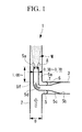
- Fig. 1 shows piping 1 having a fluid-mixing region M.
- the piping 1 includes a main pipe (first pipe) 2 and a branch pipe (second pipe) 3.
- the main pipe 2 has an inner diameter D and is formed of metal.
- high-temperature water high-temperature fluid flows from bottom to top.
- the branch pipe 3 is connected to an outer wall of the main pipe 2 perpendicularly.
- the branch pipe 3 is formed of metal, and low-temperature water (low-temperature fluid) having a lower temperature than the high-temperature water flowing through the main pipe 2 flows through the branch pipe 3.
- low-temperature water flows from right to left in the branch pipe 3, passes through a reducer (inner pipe) 5, and flows into the main pipe 2 through a downstream end 5a of the reducer 5.
- the reducer 5 includes a funnel-like portion 5c whose inner diameter decreases gradually from the upstream end 5b toward the downstream side, an elbow portion 5d connected to the funnel-like portion 5c and bent perpendicularly, and an end portion 5e connected to the elbow portion 5d and extending linearly to the downstream end 5a.
- the end portion 5e and the elbow portion (downstream portion) 5d are connected together by welding and have a weld line (weld) 5f formed at their joint.
- the length from the downstream end 5a of the end portion 5e to the weld line 5f is equal to or larger than the inner diameter D of the main pipe 2.
- the inner diameter of the end portion 5e is 0.3 to 0.7 times the inner diameter D of the main pipe 2.
- a concave portion 6 is provided between the inner wall of the branch pipe 3 and the outer wall of the reducer 5.
- This concave portion 6 forms a stagnation region T at the joint between the main pipe 2 and the branch pipe 3.
- the high-temperature water in the main pipe 2 stagnates in the stagnation region T, where it prevents a supply of new high-temperature water.
- the high-temperature water retained in that region T radiates heat toward the low-temperature water.
- a thermal sleeve is formed to reduce temperature variations.
- the high-temperature water flows through the main pipe 2 from bottom to top while the low-temperature water flows through the branch pipe 3 from right to left.
- the high-temperature water flowing through the main pipe 2 has a higher velocity than the low-temperature water flowing through the branch pipe 3.
- the low-temperature water flowing through the main pipe 2 flows upward along the periphery of the reducer 5. Some of the high-temperature water is retained in the stagnation region T formed at the joint between the main pipe 2 and the branch pipe 3.
- the low-temperature water flowing through the branch pipe 3 enters the funnel-like portion 5c through the upstream end 5b of the reducer 5.
- the funnel-like portion 5c whose inner diameter decreases gradually, accelerates the low-temperature water.
- the elbow portion 5d bends the flow direction of the low-temperature water passing through the funnel-like portion 5c at a right angle before it flows to the end portion 5e.
- the low-temperature water then flows out of the downstream end 5a of the end portion 5e.
- the low-temperature water flowing out of the downstream end 5a is mixed with the high-temperature water flowing along the periphery of the reducer 5 in the mixing region M.
- the high-velocity, high-temperature water flows from the downstream end 5a of the reducer 5 back to the upstream side, as shown by arrows A in Fig. 1 .
- some high-temperature water flows back into the reducer 5, thus causing temperature fluctuations due to temperature variations in the end portion 5e of the reducer 5.
- the high-temperature fluid does not reach the weld line 5f because the length from the downstream end 5a of the reducer 5 to the weld line 5f is equal to or larger than the inner diameter D of the main pipe 2. Therefore, no temperature interface with positional variations is formed near the weld line 5f, where the fatigue strength is lower than in the unwelded portion. This prevents breakage due to thermal fatigue at the weld line 5f.
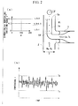
- Fig. 2 illustrates experimental results showing the effect of this embodiment.
- the velocity ratio (Ub/Um) of the velocity Ub of the low-temperature water flowing through the branch pipe 3 to the velocity Um of the high-temperature water flowing through the main pipe 2 is 0.05 or less.
- the velocity Um of the high-temperature water refers to the velocity upstream of the joint with the branch pipe 2, and the velocity Ub of the low-temperature water refers to the velocity before entry into the reducer 5.
- the individual velocities have been increased as a result of decreased flow channel areas. This, however, does not change the relationship that the velocity Um of the high-temperature water is higher than the velocity Ub of the low-temperature water at the downstream end 5a of the reducer 5.
- the velocity ratio at the downstream end 5a of the reducer 5 is about 0.1.
- the graph on the left of (a) in Fig. 2 shows the dimensionless temperature variation range T * at a circumferential position ⁇ of the end portion 5e of the reducer 5.
- the length from the downstream end 5a of the reducer 5 to the weld line 5f is equal to or larger than the inner diameter D of the main pipe 2 as in this embodiment, the high-temperature fluid does not reach the weld line 5f, which therefore suffers no breakage due to thermal fatigue.
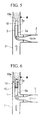
- This embodiment differs from the first embodiment in that a small-diameter portion 5g is provided at the end portion 5e of the reducer 5, and the other features are identical. Hence, the identical portions will not be described.
- the small-diameter portion 5g is provided on the downstream side of the end portion 5e of the reducer 5 and has a smaller inner diameter than the upstream side thereof.
- the small-diameter portion 5g further accelerates the low-temperature water flowing through the branch pipe 3 and guided into the reducer 5. This prevents the high-temperature water flowing along the outside of the reducer 5 from flowing back into the reducer 5. Thus, no temperature interface reaches a deep level inside the reducer 5, so that the possibility of breakage at the weld line 5f due to thermal fatigue is eliminated.
- Fig. 4 shows a modification of this embodiment. Specifically, swirling vanes (swirling part) 8 are added to the structure of Fig. 3 . These swirling vanes 8 are disposed inside the main pipe 2 upstream of the joint with the branch pipe 3. The swirling vanes 8 apply a swirling force to the high-temperature fluid flowing through the main pipe 2 about the axis of the main pipe 2. This causes the high-temperature fluid flowing through the main pipe 2 to swirl around the reducer 5, thus facilitating the mixing with the low-temperature fluid flowing out of the reducer 5 in the fluid-mixing region M.
- the present invention is not limited thereto, and a configuration in which the low-temperature water flows through the main pipe 2 and the high-temperature water flows through the branch pipe 3 is also possible.
- This embodiment differs from the first embodiment in that an inner cylinder 10 is provided at the end of the reducer 5, and the other features are identical. Hence, the identical portions will not be described.
- the inner cylinder 10 is inserted in the end portion 5e of the reducer 5.
- a downstream end 10a of the inner cylinder 10 is disposed downstream of the downstream end 5a of the reducer 5.
- a gap having an annular cross section is formed between the outer circumferential wall of the inner cylinder 10 and the inner circumferential wall of the end portion 5e of the reducer 5.
- the inner cylinder 10 is disposed in the reducer 5 with the gap formed between the inner circumferential wall of the reducer 5 and the outer circumferential wall of the inner cylinder 10, the low-temperature water flowing through the reducer 5 is split into a peripheral flow between the outside of the inner cylinder 10 and the inside of the reducer 5 and a central flow through the inside of the inner cylinder 10.
- the peripheral flow split from the central flow by the inner cylinder 10, forms a thin layer which facilitates the mixing of the peripheral flow emerging from the downstream end of the reducer 5 with the high-temperature water flowing outside the reducer 5.
- the central flow split from the peripheral flow by the inner cylinder 10, emerges from the downstream end 10a of the inner cylinder 10 and forms a flow having a small cross-sectional area (i.e., a narrow flow) which facilitates the mixing with the high-temperature water.
- downstream end 10a of the inner cylinder 10 is disposed downstream of the downstream end 5a of the reducer 5, so that the mixing is performed in two steps: first, mixing the peripheral flow with the high-temperature water, and second, mixing the central flow with the high-temperature water. This further facilitates the mixing with the high-temperature water.
- Fig. 6 shows a modification of this embodiment. Specifically, swirling vanes 12 are added to the structure of Fig. 5 . These swirling vanes 12 are fixed between the outer circumferential wall of the inner cylinder 10 and the inner circumferential wall of the reducer 5.
- the swirling vanes 12 thus provided can apply a swirling force to the peripheral flow of the low-temperature water between the outside of the inner cylinder 10 and the inside of the reducer 5. This facilitates the mixing with the high-temperature water.
- the inner cylinder 10 can reliably be supported because the swirling vanes 12 are provided between the inner circumferential wall of the reducer 5 and the outer circumferential wall of the inner cylinder 10 so as to hold the inner cylinder 10.
- the relationship between the velocity of the high-temperature water flowing through the main pipe 2 and the velocity of the low-temperature water flowing through the branch pipe 3 may be reversed in this embodiment. That is, the high-temperature water flowing through the main pipe 2 may have a lower velocity than the low-temperature water flowing through the branch pipe 3.
- the present invention is not limited thereto, and a configuration in which the low-temperature water flows through the main pipe 2 and the high-temperature water flows through the branch pipe 3 is also possible.
- This embodiment differs from the first embodiment in that the downstream side of the main pipe 2 and the downstream side of the reducer 5 are bent, and the other features are identical. Hence, the identical portions will not be described.
- This embodiment relates to the case where the downstream side of the main pipe 2 is bent.
- the low-temperature fluid flowing out of the reducer 5 may collide with the bent portion 2a before being sufficiently mixed with the high-temperature fluid. In that case, the bent portion 2a would experience temperature fluctuations which could cause thermal stress or thermal fatigue.
- the end portion 5e of the reducer 5 extends downstream of the bent portion 2a of the main pipe 2, as shown in Fig. 7(a) .
- a bent portion 5h is provided in the end portion 5e of the reducer 5, with its downstream end 5a positioned downstream of the bent portion 2a of the main pipe 2.
- the fluid-mixing region M is provided downstream of the bent portion 2a of the main pipe 2. This prevents thermal fatigue that could occur at the bent portion 2a of the main pipe 2, as in Fig. 7(b) .
- Fig. 8 shows a modification of this embodiment. Specifically, swirling vanes (swirling part) 14 are added to the structure of in Fig. 7(a) . These swirling vanes 14 are fixed between the inner circumferential wall of the main pipe 2 and the outer circumferential wall of the reducer 5. Preferably, the swirling vanes 14 are provided on the end portion 5e of the reducer 5 upstream of the bent portion 5h.
- the swirling vanes 14 thus provided can apply a swirling force to the high-temperature water flowing between the outside of the reducer 5 and the inside of the main pipe 2. This facilitates the mixing.
- the reducer 5 extends downstream of the bent portion 2a of the main pipe 2; this may be disadvantageous in terms of the rigidity with which the end portion 5e of the reducer 5 is supported.
- the rigidity with which the reducer 5 is supported can be enhanced because the swirling vanes 14 are provided between the inner circumferential wall of the main pipe 2 and the outer circumferential wall of the reducer 5 so as to hold the end portion 5e of the reducer 5.
- the relationship between the velocity of the high-temperature water flowing through the main pipe 2 and the velocity of the low-temperature water flowing through the branch pipe 3 may be reversed in this embodiment. That is, the high-temperature water flowing through the main pipe 2 may have a lower velocity than the low-temperature water flowing through the branch pipe 3.
- the present invention is not limited thereto, and a configuration in which the low-temperature water flows through the main pipe 2 and the high-temperature water flows through the branch pipe 3 is also possible.
- This embodiment differs from the first embodiment in that a wide portion 2b is formed in the main pipe 2, and the other features are identical. Hence, the identical portions will not be described.
- the wide portion 2b is provided at the position of the main pipe 2 corresponding to the fluid-mixing region M.
- the wide portion 2b has a larger inner diameter than the upstream side of the main pipe 2.
- the downstream side of the wide portion 2b is connected to a portion of the main pipe 2 which has the same inner diameter as before the wide portion 2b.
- the wide portion 2b decreases the velocity of the high-temperature water flowing through the main pipe 2 in the fluid-mixing region M to reduce the velocity difference between the high-temperature water and the low-temperature water, which has a lower velocity and flows out of the end portion 5e of the reducer 5, thus lowering confluence resistance.
- an upstream curved portion 2b1 having a gradually increasing inner diameter is provided on the upstream side of the wide portion 2b while a downstream curved portion 2b2 having a gradually decreasing inner diameter is provided on the downstream side of the wide portion 2b.
- the wide portion 2b may have a reducer shape. Specifically, an upstream conical portion 2b3 whose inner diameter increases gradually at a constant rate is provided on the upstream side of the wide portion 2b while a downstream conical portion 2b4 whose inner diameter decreases gradually at a constant rate is provided on the downstream side of the wide portion 2b.
- This allows for smooth deceleration and acceleration of the high-temperature water, as in the embodiment of Fig. 10 , thus minimizing the fluid loss.
- a large-diameter pipe 2c having a larger inner diameter than the main pipe 2 may be provided at the position corresponding to the fluid-mixing region M.
- the large-diameter pipe 2c is a cylindrical metal pipe that is slightly longer than the fluid-mixing region M.
- Flanges 2c1 and 2c2 are provided at the upstream and downstream ends, respectively, of the large-diameter pipe 2c and are joined to upstream and downstream main pipes 2, respectively.
- a large-diameter portion can be provided simply by flange connection of the large-diameter pipe 2c, having the flanges 2c1 and 2c2, to the main pipes 2. This reduces the steps in the installation operation, as well as installation costs.
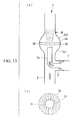
- stator vanes 20 may be installed in the wide portion 2b.
- the plurality of stator vanes (swirling part) 20 are arranged so as to extend radially, as shown in Fig. 12(b) , which is a cross-sectional view of the wide portion 2b.
- These stator vanes 20 apply a swirling force to the high-temperature water to facilitate the mixing with the low-temperature water.
- the present invention is not limited thereto, and a configuration in which the low-temperature water flows through the main pipe 2 and the high-temperature water flows through the branch pipe 3 is also possible.
- This embodiment differs from the first embodiment in that a wide pipe 22 is formed at the end of the reducer 5 in the case where the low-temperature fluid flowing through the branch pipe 3 has a higher velocity than the high-temperature fluid flowing through the main pipe 2, and the other features are identical. Hence, the identical portions will not be described.
- the wide pipe 22 is formed at the end of the reducer 5 so as to extend along the central axis of the main pipe 2.
- the wide pipe 22 is a conical metal pipe whose inner diameter increases gradually toward its downstream end.
- the wide pipe 22 decreases the velocity of the low-temperature water flowing through the wide pipe 22.
- the velocity of the high-temperature water is increased in a region having an annular cross section between the wide pipe 22 and the main pipe 2 because this region is gradually narrowed. This reduces the velocity difference between the low-temperature fluid and the high-temperature fluid, which has a lower velocity and flows through the main pipe 2, thus lowering the confluence resistance in the fluid-mixing region M.
- the present invention is not limited thereto, and a configuration in which the low-temperature water flows through the main pipe 2 and the high-temperature water flows through the branch pipe 3 is also possible.
- This embodiment differs from the first embodiment in that a bypass pipe 24 is connected to the reducer 5, and the other features are identical. Hence, the identical portions will not be described.
- the elbow portion 5d of the reducer 5 has the bypass pipe (intake part) 24, which extends along the central axis of the main pipe 2 so as to face the upstream side.
- the bypass pipe 24 is, for example, a cylindrical metal pipe.
- the reducer 5 can take in the fluid through the bypass pipe 24 before it reaches the fluid-mixing region M. Some of the high-temperature fluid can thus be mixed with the low-temperature water before it reaches the fluid-mixing region M. This enables two-step mixing, which can decrease the temperature difference between the high-temperature water and the low-temperature water stepwise to suppress the temperature difference on the inner metal surface of the pipe. In addition, the confluence resistance can be reduced.
- the bypass pipe 24 may be replaced with, for example, an opening formed in the wall of the elbow portion 5d or the end portion 5e.
- the relationship between the velocity of the high-temperature water flowing through the main pipe 2 and the velocity of the low-temperature water flowing through the branch pipe 3 may be reversed in this embodiment. That is, the high-temperature water flowing through the main pipe 2 may have a lower velocity than the low-temperature water flowing through the branch pipe 3.
- the present invention is not limited thereto, and a configuration in which the low-temperature water flows through the main pipe 2 and the high-temperature water flows through the branch pipe 3 is also possible.
- the upstream end 5b of the reducer 5 is joined to the inner circumferential wall of the branch pipe 3 in the description of the first to seventh embodiments, the present invention is not limited thereto. As shown in Fig. 9 , for example, the upstream end 5b of the reducer 5 may be joined to a position of the inner circumferential wall of the main pipe 2 upstream of the joint between the branch pipe 3 and the main pipe 2.
Landscapes
- Engineering & Computer Science (AREA)
- Chemical & Material Sciences (AREA)
- Chemical Kinetics & Catalysis (AREA)
- General Engineering & Computer Science (AREA)
- Mechanical Engineering (AREA)
- Health & Medical Sciences (AREA)
- Public Health (AREA)
- Water Supply & Treatment (AREA)
- Branch Pipes, Bends, And The Like (AREA)
- Pipe Accessories (AREA)
- Heat-Exchange Devices With Radiators And Conduit Assemblies (AREA)
- Rigid Pipes And Flexible Pipes (AREA)
Applications Claiming Priority (3)
| Application Number | Priority Date | Filing Date | Title |
|---|---|---|---|
| JP2005283694 | 2005-09-29 | ||
| JP2006260367A JP2007120755A (ja) | 2005-09-29 | 2006-09-26 | 流体混合領域を有する配管 |
| PCT/JP2006/319302 WO2007037328A1 (fr) | 2005-09-29 | 2006-09-28 | Conduite a zone de melange de liquides |
Publications (1)
| Publication Number | Publication Date |
|---|---|
| EP1930645A1 true EP1930645A1 (fr) | 2008-06-11 |
Family
ID=37899752
Family Applications (1)
| Application Number | Title | Priority Date | Filing Date |
|---|---|---|---|
| EP06810749A Withdrawn EP1930645A1 (fr) | 2005-09-29 | 2006-09-28 | Conduite a zone de melange de liquides |
Country Status (7)
| Country | Link |
|---|---|
| US (1) | US8011392B2 (fr) |
| EP (1) | EP1930645A1 (fr) |
| JP (1) | JP2007120755A (fr) |
| KR (1) | KR100970052B1 (fr) |
| CA (1) | CA2617340C (fr) |
| NO (1) | NO20080509L (fr) |
| WO (1) | WO2007037328A1 (fr) |
Cited By (2)
| Publication number | Priority date | Publication date | Assignee | Title |
|---|---|---|---|---|
| WO2011101038A1 (fr) * | 2010-02-22 | 2011-08-25 | Haldor Topsøe A/S | Dispositif et procédé pour mélanger un gaz corrosif avec un gaz non corrosif |
| FR3005429A1 (fr) * | 2013-05-07 | 2014-11-14 | Air Liquide France Ind | Procede d'injection sans contact de co2 diphasique "gaz - solide" d'un systeme fixe vers un dispositif mobile de facon a produire un nuage de particules ephemeres |
Families Citing this family (16)
| Publication number | Priority date | Publication date | Assignee | Title |
|---|---|---|---|---|
| JP5302561B2 (ja) * | 2008-03-28 | 2013-10-02 | アネスト岩田株式会社 | 多液塗装用塗料供給装置の混合装置 |
| US10290381B2 (en) * | 2011-12-30 | 2019-05-14 | Ge-Hitachi Nuclear Energy Americas Llc | Method and apparatus for a high-temperature deposition solution injector |
| US20130180595A1 (en) * | 2012-01-13 | 2013-07-18 | Uop, Llc | Vessel, distribution tray, and method for passing one or more fluids |
| US9182066B2 (en) * | 2012-12-19 | 2015-11-10 | Specialized Desanders Inc. | Erosion resistant flow conduit |
| US9761336B2 (en) | 2012-12-20 | 2017-09-12 | Ge-Hitachi Nuclear Energy Americas Llc | Insulated solution injector, system including the same, and method of injecting using the same |
| JP6104829B2 (ja) * | 2014-02-25 | 2017-03-29 | 株式会社東芝 | 嫌気性水処理システム |
| CN104235549A (zh) * | 2014-08-20 | 2014-12-24 | 浙江理工大学 | 可整流的反应流出物管道注水结构 |
| US20160177814A1 (en) * | 2014-12-23 | 2016-06-23 | Caterpillar Inc. | Removal of Heat in Exhaust Shielding with Jacket Fluid Cooled Components |
| US20160177806A1 (en) * | 2014-12-23 | 2016-06-23 | Caterpillar Inc. | Exhaust Outlet Elbow Center Divider Connection |
| CN106481924B (zh) * | 2015-08-26 | 2019-03-22 | 中石化洛阳工程有限公司 | 一种用于冷热流体的套管式混合器 |
| US10515729B2 (en) | 2015-11-04 | 2019-12-24 | Ge-Hitachi Nuclear Energy Americas Llc | Insulated solution injector including an insulating liner, system including the same, and method of injecting using the same |
| US10619656B1 (en) * | 2017-05-31 | 2020-04-14 | Daniel A. Handley | Fluid turbulence inducement apparatus and system |
| KR102098642B1 (ko) * | 2018-10-31 | 2020-04-09 | 서울대학교산학협력단 | 조류 이송 장치가 구비된 조류 제거 선박 |
| KR102098638B1 (ko) * | 2018-10-31 | 2020-04-09 | 서울대학교산학협력단 | 쌍동선 형태의 조류 제거 선박 |
| KR102136142B1 (ko) * | 2020-03-13 | 2020-07-21 | 최상호 | 관통형 배수펌프 및 이를 이용한 유체배관 내의 유체 배수장치 |
| CN114198583B (zh) * | 2021-11-05 | 2023-06-20 | 中国船舶重工集团公司第七一九研究所 | 一种交汇管热疲劳缓解系统及热疲劳缓解控制方法 |
Family Cites Families (25)
| Publication number | Priority date | Publication date | Assignee | Title |
|---|---|---|---|---|
| US2784948A (en) * | 1951-05-18 | 1957-03-12 | Crown Cork & Seal Co | Liquid mixing device |
| US3847375A (en) * | 1972-10-12 | 1974-11-12 | Basf Ag | Method and apparatus for mixing liquids |
| US3818938A (en) * | 1972-10-16 | 1974-06-25 | Universal Oil Prod Co | Fluid mixing apparatus |
| KR810000590B1 (ko) | 1977-02-10 | 1981-06-05 | 에프 에이 덧데러 | 주형 및 정반의 수선방법 |
| KR810000590Y1 (ko) * | 1980-02-13 | 1981-05-28 | 주식회사럭키 | 열 교환관 |
| JPS59217091A (ja) | 1983-05-23 | 1984-12-07 | 株式会社日立製作所 | 分岐管構造 |
| FR2562439B1 (fr) | 1984-04-06 | 1989-10-13 | Degremont | Appareil pour le melange rapide de deux fluides |
| JPS6199794A (ja) * | 1984-10-22 | 1986-05-17 | 株式会社東芝 | 配管継手装置 |
| JPS6263294A (ja) * | 1985-09-11 | 1987-03-19 | 株式会社東芝 | サ−マルスリ−ブ付配管構造 |
| JPS6275194A (ja) | 1985-09-30 | 1987-04-07 | 石川島播磨重工業株式会社 | 流体混合管 |
| JPS6426005A (en) * | 1987-07-21 | 1989-01-27 | Nippon Gijutsu Kaihatsu Center | Method for transferring fluid and swirl flow generator |
| JPH0177189U (fr) | 1987-11-11 | 1989-05-24 | ||
| JPH0352700U (fr) | 1989-09-28 | 1991-05-22 | ||
| US5289976A (en) * | 1991-12-13 | 1994-03-01 | Mobil Oil Corporation | Heavy hydrocarbon feed atomization |
| JPH07181282A (ja) | 1993-12-24 | 1995-07-21 | Toshiba Corp | 再循環水入口ノズルの表面改質方法 |
| JPH07243595A (ja) * | 1994-03-09 | 1995-09-19 | Hitachi Ltd | 混合流配管構造 |
| JPH08109386A (ja) | 1994-10-07 | 1996-04-30 | Mitsubishi Oil Co Ltd | 噴射式乳化装置 |
| JP3410861B2 (ja) * | 1995-06-29 | 2003-05-26 | 株式会社東芝 | 配管合流継手 |
| JP3127394B2 (ja) | 1996-12-26 | 2001-01-22 | 永和調査設計株式会社 | 染色工場に於ける排水処理方法 |
| US6186658B1 (en) | 1997-03-14 | 2001-02-13 | Nippon Mitsubishi Oil Corporation | Apparatus for mixing a fluid feedstock with particles |
| JP3662709B2 (ja) * | 1997-03-14 | 2005-06-22 | 新日本石油株式会社 | 混合装置 |
| US5948241A (en) * | 1997-08-05 | 1999-09-07 | Owen; Hartley | Orifice plate feed nozzle and atomization process |
| DE10024539A1 (de) | 2000-05-18 | 2001-05-31 | Zimmer Ag | Berstschutzeinrichtung |
| JP2002320836A (ja) * | 2001-04-27 | 2002-11-05 | Mitsubishi Heavy Ind Ltd | 混合促進構造 |
| JP2005016686A (ja) | 2003-06-27 | 2005-01-20 | Mitsubishi Heavy Ind Ltd | 配管合流部構造及びその製造方法 |
-
2006
- 2006-09-26 JP JP2006260367A patent/JP2007120755A/ja active Pending
- 2006-09-28 CA CA2617340A patent/CA2617340C/fr not_active Expired - Fee Related
- 2006-09-28 EP EP06810749A patent/EP1930645A1/fr not_active Withdrawn
- 2006-09-28 KR KR1020087001963A patent/KR100970052B1/ko not_active Expired - Fee Related
- 2006-09-28 US US11/989,526 patent/US8011392B2/en active Active
- 2006-09-28 WO PCT/JP2006/319302 patent/WO2007037328A1/fr not_active Ceased
-
2008
- 2008-01-28 NO NO20080509A patent/NO20080509L/no not_active Application Discontinuation
Non-Patent Citations (1)
| Title |
|---|
| See references of WO2007037328A1 * |
Cited By (3)
| Publication number | Priority date | Publication date | Assignee | Title |
|---|---|---|---|---|
| WO2011101038A1 (fr) * | 2010-02-22 | 2011-08-25 | Haldor Topsøe A/S | Dispositif et procédé pour mélanger un gaz corrosif avec un gaz non corrosif |
| US9643132B2 (en) | 2010-02-22 | 2017-05-09 | Haldor Topsoe A/S | Apparatus and method for mixing of corrosive and non-corrosive gas |
| FR3005429A1 (fr) * | 2013-05-07 | 2014-11-14 | Air Liquide France Ind | Procede d'injection sans contact de co2 diphasique "gaz - solide" d'un systeme fixe vers un dispositif mobile de facon a produire un nuage de particules ephemeres |
Also Published As
| Publication number | Publication date |
|---|---|
| US8011392B2 (en) | 2011-09-06 |
| NO20080509L (no) | 2008-03-25 |
| CA2617340C (fr) | 2012-04-24 |
| KR100970052B1 (ko) | 2010-07-16 |
| KR20080016974A (ko) | 2008-02-22 |
| WO2007037328A1 (fr) | 2007-04-05 |
| JP2007120755A (ja) | 2007-05-17 |
| CA2617340A1 (fr) | 2007-04-05 |
| US20090090424A1 (en) | 2009-04-09 |
Similar Documents
| Publication | Publication Date | Title |
|---|---|---|
| EP1930645A1 (fr) | Conduite a zone de melange de liquides | |
| US8845178B2 (en) | In-line-type fluid mixer | |
| US8132961B1 (en) | Flow plug with length-to-hole size uniformity for use in flow conditioning and flow metering | |
| US11291966B2 (en) | Mixer and vaporization apparatus | |
| CN102735297A (zh) | 一种超声波流量计前置流动调整器 | |
| CN104394971B (zh) | 静态混合器 | |
| KR102116746B1 (ko) | 유체혼합소자 | |
| CN104948351A (zh) | 用于至少两个流体流的均化设备 | |
| JP2011025171A (ja) | ベンチュリ管を用いた流体の混合方法、ベンチュリ型混合装置 | |
| KR101736082B1 (ko) | 내연기관으로부터 배기가스 샘플을 제거하는 시스템 | |
| CN101233359A (zh) | 具有流体混合区域的配管 | |
| CN211864584U (zh) | 一种微动力气液或液液混合纳米级流体发生器 | |
| JP4995157B2 (ja) | 配管合流部構造及びその製造方法 | |
| JPH07243596A (ja) | 混合流配管構造 | |
| US20220241740A1 (en) | Mixing device with reversed coiled configuration and use thereof | |
| JP2009219957A (ja) | 気液混合システム及び気液混合方法 | |
| JP2005016686A (ja) | 配管合流部構造及びその製造方法 | |
| CA2460549A1 (fr) | Dispositif pour melanger deux courants fluidiques qui sont a l'origine conduits de maniere separee dans un moteur a reaction a double circuit | |
| EP4145094A1 (fr) | Conditionneur de débit pour de graves perturbations de flux | |
| JPH09150045A (ja) | 粉流体混合装置 | |
| JP5839324B2 (ja) | 攪拌羽根付き管 | |
| RU34233U1 (ru) | Устройство для подготовки к сжиганию топливной смеси | |
| JP4690836B2 (ja) | 高温流体と低温流体を混合させる配管構造 | |
| RU2442071C1 (ru) | Способ транспорта жидкостей по трубопроводу | |
| RU2778443C2 (ru) | Устройство и способ для измерения скорости и расхода потока текучей среды |
Legal Events
| Date | Code | Title | Description |
|---|---|---|---|
| PUAI | Public reference made under article 153(3) epc to a published international application that has entered the european phase |
Free format text: ORIGINAL CODE: 0009012 |
|
| 17P | Request for examination filed |
Effective date: 20080131 |
|
| AK | Designated contracting states |
Kind code of ref document: A1 Designated state(s): DE FR GB IT SE |
|
| DAX | Request for extension of the european patent (deleted) | ||
| RBV | Designated contracting states (corrected) |
Designated state(s): DE FR GB IT SE |
|
| STAA | Information on the status of an ep patent application or granted ep patent |
Free format text: STATUS: THE APPLICATION HAS BEEN WITHDRAWN |
|
| 18W | Application withdrawn |
Effective date: 20130108 |