EP1932625A2 - Appareil d'outillage manuel électrique - Google Patents
Appareil d'outillage manuel électrique Download PDFInfo
- Publication number
- EP1932625A2 EP1932625A2 EP07122207A EP07122207A EP1932625A2 EP 1932625 A2 EP1932625 A2 EP 1932625A2 EP 07122207 A EP07122207 A EP 07122207A EP 07122207 A EP07122207 A EP 07122207A EP 1932625 A2 EP1932625 A2 EP 1932625A2
- Authority
- EP
- European Patent Office
- Prior art keywords
- pivot member
- switch
- hand tool
- electric hand
- side pivot
- Prior art date
- Legal status (The legal status is an assumption and is not a legal conclusion. Google has not performed a legal analysis and makes no representation as to the accuracy of the status listed.)
- Granted
Links
Images


Classifications
-
- B—PERFORMING OPERATIONS; TRANSPORTING
- B25—HAND TOOLS; PORTABLE POWER-DRIVEN TOOLS; MANIPULATORS
- B25D—PERCUSSIVE TOOLS
- B25D16/00—Portable percussive machines with superimposed rotation, the rotational movement of the output shaft of a motor being modified to generate axial impacts on the tool bit
- B25D16/006—Mode changers; Mechanisms connected thereto
-
- B—PERFORMING OPERATIONS; TRANSPORTING
- B25—HAND TOOLS; PORTABLE POWER-DRIVEN TOOLS; MANIPULATORS
- B25D—PERCUSSIVE TOOLS
- B25D2211/00—Details of portable percussive tools with electromotor or other motor drive
- B25D2211/006—Parallel drill and motor spindles
-
- B—PERFORMING OPERATIONS; TRANSPORTING
- B25—HAND TOOLS; PORTABLE POWER-DRIVEN TOOLS; MANIPULATORS
- B25D—PERCUSSIVE TOOLS
- B25D2211/00—Details of portable percussive tools with electromotor or other motor drive
- B25D2211/06—Means for driving the impulse member
- B25D2211/062—Cam-actuated impulse-driving mechanisms
- B25D2211/064—Axial cams, e.g. two camming surfaces coaxial with drill spindle
-
- B—PERFORMING OPERATIONS; TRANSPORTING
- B25—HAND TOOLS; PORTABLE POWER-DRIVEN TOOLS; MANIPULATORS
- B25D—PERCUSSIVE TOOLS
- B25D2216/00—Details of portable percussive machines with superimposed rotation, the rotational movement of the output shaft of a motor being modified to generate axial impacts on the tool bit
- B25D2216/0007—Details of percussion or rotation modes
- B25D2216/0023—Tools having a percussion-and-rotation mode
-
- B—PERFORMING OPERATIONS; TRANSPORTING
- B25—HAND TOOLS; PORTABLE POWER-DRIVEN TOOLS; MANIPULATORS
- B25D—PERCUSSIVE TOOLS
- B25D2216/00—Details of portable percussive machines with superimposed rotation, the rotational movement of the output shaft of a motor being modified to generate axial impacts on the tool bit
- B25D2216/0007—Details of percussion or rotation modes
- B25D2216/0038—Tools having a rotation-only mode
Definitions
- the invention relates to an electric hand tool with the features according to the preamble of claim 1.
- the hand tool on a transmission, which comprises at least two switching stages.
- the hand tool has an optional on and off Schlagwerks and a fashion switch, by means of both the shift between the switching stages back and forth switchable and the hammer mechanism is switched on and off.
- the fashion switch is motion-coupled both with gear shifting means of the gearbox and with Schlagtechnikschaltstoffn the striking mechanism.
- both the various gear shift stages and the percussion mechanism can be switched via a single handle. This allows both a more comfortable operation and easier production of the device.
- a switching device for a power tool which has a rotatably mounted control element and two separate switching elements.
- a first switching element is used for switching a gearbox and a second switching element for activating an electronic switching operation, which serves for example to connect or disconnect a striking mechanism.
- transmission elements are provided, via which a rotational movement of the operating element into mutually perpendicular displacements of the switching elements is convertible.
- a disadvantage of the known switching device is that the vertically displaceable switching elements require a relatively large space.
- the present invention has for its object to avoid the disadvantages mentioned in an electric hand tool and to reduce the required space.
- an electric hand tool with the features of claim 1, wherein the Schlagtechnikschaltstoff have a pivoting mechanism by means of the mode switch between an active position in which the percussion is activated, and a passive position in which the impact mechanism is deactivated, pivotable is.
- a pivoting mechanism can be designed so that it occupies at least predominantly the same space in different switching positions.
- the swivel mechanism has a switch-side swivel member which is pivotably held on a rotary bearing. This is motion-coupled with the fashion switch and actuates actuating means, depending on their position, the percussion is switched on and off.
- a stable pivot mechanism can be provided, which holds the percussion safely in a selected operating condition.
- an eccentric element is provided on the fashion switch, via which both the switch-side pivot member and the transmission shifting means can be actuated.
- the switching positions of the transmission can be tuned directly with the switching positions of the striking mechanism. In this way, it can be ensured, for example, that at the same time a speed which is particularly suitable for this purpose is set when the percussion mechanism is switched on.
- the adjusting means on a second pivot bearing transversely to the switch-side pivot member pivotally held on the beat mechanism side pivot member.
- the impact mechanism-side pivot member on a blocking stop by means of which a first ratchet disk of the percussion mechanism in the passive position with respect to a second ratchet wheel is spaced apart.
- the striking mechanism can be switched off in a particularly simple manner.
- the impact mechanism-side pivot member is advantageously pivoted by the switch-side pivot member in the active position in a position in which the spacing of the Ratchet discs is lifted by the blocking stop. In this way, the switching on and off of the striking mechanism by a particularly simple but stable switching arrangement is possible.
- the impact mechanism-side pivot member is biased in the passive position to exclude an unintentional connection of the percussion mechanism with appropriate position of the fashion switch.
- the bias is generated by a leg spring.
- a leg spring is particularly well attachable to the impact mechanism side pivot member.
- the leg spring needs only a small additional space.
- first pivot member and the second pivot member are formed as bending punched parts, whereby the pivot mechanism is inexpensive to produce.
- the gear shift means comprise a sliding element, by means of which a gear block of the gearbox between the switching stages is displaceable and which is designed as a bending punched part.
- a gear block of the gearbox between the switching stages is displaceable and which is designed as a bending punched part.
- the first pivot bearing between the switch-side pivot member and the sliding element is provided and formed by a pin engaging in a passage.
- the passage can be formed at one of the two bending punched parts in its manufacture with and the pin on the other bending punched part, for example, tumble riveted, whereby the first pivot bearing is particularly inexpensive to produce.
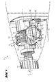
- Fig. 1 shows a front part of a hand tool 2 in the form of a percussion drill.
- This has a fashion switch 4, by means of which both a manual transmission 6 and a recorded in a striking mechanism housing 8 striking mechanism 10 back and forth between different switching stages is switched.
- the fashion switch 4 is designed as a rotary switch.
- a tool spindle 12 on which a tool holder 14 is held, on the one hand driven by the transmission 6 at different rotational speeds about a working axis A around.
- the tool spindle 12 can optionally additionally be acted upon by the percussion mechanism 10 along the working axis A in a recurring manner with a pulse-like striking force S.
- the tool spindle 12 is both rotatable and axially displaceable.
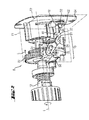
- both gear shift means 16 for actuating the gearbox 6 and percussion switching means 18 for actuating the impact mechanism 10 includes.
- the gear shift means 16 as well as the striking mechanism switching means 18 are coupled in a motion-coupled manner to the mode switch 4.
- the gear shift means 14 are essentially formed by a sliding element 20, via the two opposite end faces S1, S2 of a two-stage gear block 22 of the gearbox 6 can be acted upon with axial pressure.
- the gear block 22 is slidably mounted in the axial direction but rotatably mounted on the tool spindle 12 and can thus be moved back and forth via the sliding element 20 along the working axis A.
- the striking mechanism switching means 18 comprise a pivoting mechanism, which has a switch-side pivot member 24 and a hammer-side pivot member 26.
- the switch-side pivot member 24 in this case comprises a with the fashion switch 4 engaged first pivot arm 28 and is used to actuate the impact mechanism side pivot member 26.
- the impact mechanism side pivot member 26 acts as a means of adjustment by means of which the striking mechanism 10 is switched on and off.
- Fig. 1 shows the fashion switch 6 in a defined by an arrow P1 first rotational position in which the tool spindle 12 is driven at a low speed only and the pivot members 24, 26 are in a passive position in which the striking mechanism 6 is deactivated.
- the mode switch 4 is rotated from this first rotational position in the direction of rotation D in an offset by about 180 ° second rotational position and another 80 to 90 ° in a third rotational position, as indicated by dotted arrows P2 and P3 of the mode switch 4.
- Fig. 2 shows the switching arrangement 15 in one of the first rotational position of the mode switch 4 corresponding first switching position, wherein the mode switch 4, only a pin-shaped eccentric element 30 is shown.
- This eccentric 30 acts as a coupling means, which is engaged both with a set into the sliding element 20 slide 34 and with a slot 36 which is provided on the first pivot arm 28 of the switch-side pivot member 24 and as well as the gate 34 acts as a negative feedback means.
- the position of the sliding element 20 along the working axis A is determined by the engagement of the eccentric element 30 in the link 34, in which the first switching stage is set on the transmission 6.
- the gear block 22 meshes with a first drive pinion 38 of a drive, not shown.
- the eccentric element 30 sets by its engagement with the slot 36 in this first rotational position of the mode switch 4 a pivot position of the switch-side pivot member 24 fixed.
- a second pivot arm 32 of the switch-side pivot member 24 is directed downward.
- a formed on the second pivot arm 32 by a curved end portion applying element 40 is spaced in this switching position of a driving element 42 of the impact mechanism side pivot member 26 which forms a contact surface 44 which is inclined relative to a first pivot plane E1 of the switch-side pivot member 24 in which Switch-side pivot member 24 is pivotable.
- the impact mechanism-side pivot member 26 is pivotable in a second pivot plane E2, which is substantially perpendicular to the first pivot plane E1 of the switch-side pivot member 24.
- the eccentric element 30 is pivoted in a direction R during rotation of the mode switch 4, wherein the gear block 22 is displaced by means of the sliding element 20 in the direction L and the application element 40 is pivoted in the direction M.
- the second rotational position of the mode switch 4 and a second switching position of the switching device 15 according to Fig. 3 and 4 reached.
- a rear end 48 of the tool spindle 12 can be applied, whereby their displacement is blocked in the axial direction to the rear during operation.
- the impact mechanism-side pivot member 26 is biased by a leg spring 54 in the blocking position in the path of movement P.
- the striking mechanism 10 is designed as a ratchet impact mechanism and has a fixed ratchet wheel 50 which is held fixed in position in the power tool 2 and a movable ratchet wheel 52 on.
- the movable ratchet wheel 52 is fixedly connected to the tool spindle 12 and thus moves with both in the direction of rotation and in the axial direction with this.
- the movable ratchet plate 52 In the illustrated passive position, the movable ratchet plate 52 is held by the voltage applied to the blocking stop 46 rear end 48 of the tool spindle 12 in the axial direction spaced from the fixed ratchet wheel 52. An interaction of the two ratchet discs 50, 52 for acting on the tool spindle 12 with shocks is thus blocked in the second switching position of the switching assembly 15 as well as in the first switching position.
- the mode switch 4 can be further rotated in the direction of rotation D and thus the eccentric element 30 can be further pivoted in the pivoting direction R.
- the switch-side pivot member 24 is pivoted by engagement with the eccentric element 30 such that the second pivot arm 32 presses with the contact element 40 in the direction M against the driving element 42.
- the impact mechanism-side pivot member 26 is pivoted against the force of the spring 54.
- the sliding element 20 and the gear shift means 16 in total remain, however, in the second switching stage.
- the pivoting mechanism formed by the pivoting members 24, 26 is brought into an active position in which the percussion mechanism 10 can be activated.
- the blocking stop 46 is moved completely out of the axial movement path P of the displaceable tool spindle 12, as a result of which its displacement in the axial direction towards the rear during operation is no longer blocked.
- the tool spindle 12 By pressing the hand tool 2 in operation against an object, not shown, to be machined thus the tool spindle 12 can be moved along the axial movement path P.
- the movable ratchet disk 52 which rotates together with the tool spindle 12, comes into recurrent contact with the fixed ratchet disk 50 and thereby acts in a known manner on the tool spindle 12 with recurring impacts along the working axis A.
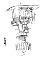
- Fig. 7 shows a gear-side plan view of the switching assembly 15 in the third switching position alone.
- the first pivot bearing D1 between the sliding element 20 and the switch-side pivot member 24 is formed by a pin 56 which projects into a cylindrical receptacle 58.
- the pin 56 is, for example, on the switch-side pivot member 24 taumelgenietet, which is formed as a stamped sheet metal part.
- the cylindrical receptacle 58 is formed by a passage, which is also made together with the rest of the sliding element 20 by bending punching a sheet metal part.
- the impact mechanism side pivot member 26 is formed by a sheet metal stamped punched part.
- the impact mechanism-side pivot member 26 in this case forms a second cylindrical receptacle 60, which forms the second pivot bearing D2 together with a housing-fixed pin 62.
- the housing-fixed pin 62 is formed on a bearing plate 64, in particular from Fig. 2 can be seen.
Landscapes
- Engineering & Computer Science (AREA)
- Mechanical Engineering (AREA)
- Percussive Tools And Related Accessories (AREA)
- Drilling And Boring (AREA)
- Transmission Devices (AREA)
Applications Claiming Priority (1)
| Application Number | Priority Date | Filing Date | Title |
|---|---|---|---|
| DE102006000515A DE102006000515A1 (de) | 2006-12-12 | 2006-12-12 | Elektrisches Handwerkzeuggerät |
Publications (3)
| Publication Number | Publication Date |
|---|---|
| EP1932625A2 true EP1932625A2 (fr) | 2008-06-18 |
| EP1932625A3 EP1932625A3 (fr) | 2008-08-27 |
| EP1932625B1 EP1932625B1 (fr) | 2010-08-04 |
Family
ID=39183115
Family Applications (1)
| Application Number | Title | Priority Date | Filing Date |
|---|---|---|---|
| EP07122207A Active EP1932625B1 (fr) | 2006-12-12 | 2007-12-04 | Appareil d'outillage manuel électrique |
Country Status (6)
| Country | Link |
|---|---|
| US (1) | US7607493B2 (fr) |
| EP (1) | EP1932625B1 (fr) |
| JP (1) | JP5201972B2 (fr) |
| CN (1) | CN101200061B (fr) |
| DE (2) | DE102006000515A1 (fr) |
| ES (1) | ES2349807T3 (fr) |
Cited By (5)
| Publication number | Priority date | Publication date | Assignee | Title |
|---|---|---|---|---|
| FR2993193A1 (fr) * | 2012-07-16 | 2014-01-17 | Bosch Gmbh Robert | Unite de commutation de machine-outil a main portative |
| WO2017102532A1 (fr) * | 2015-12-18 | 2017-06-22 | Robert Bosch Gmbh | Machine-outil portative munie d'une interface de communication |
| US9873192B2 (en) | 2013-12-11 | 2018-01-23 | Black & Decker Inc. | Rotary hammer |
| US10046450B2 (en) | 2014-07-28 | 2018-08-14 | Black & Decker Inc. | Mode change knob assembly |
| US10994403B2 (en) | 2015-12-18 | 2021-05-04 | Robert Bosch Gmbh | Hand-held power tool comprising a gearshift unit |
Families Citing this family (27)
| Publication number | Priority date | Publication date | Assignee | Title |
|---|---|---|---|---|
| FR2907695B1 (fr) * | 2006-10-27 | 2009-06-26 | Cooper Power Tools Sas Soc Par | Procede de percage d'un alesage et machine correspondante. |
| DE102006059076A1 (de) * | 2006-12-14 | 2008-06-19 | Robert Bosch Gmbh | Schlagwerk einer Elektrohandwerkzeugmaschine |
| US7798245B2 (en) * | 2007-11-21 | 2010-09-21 | Black & Decker Inc. | Multi-mode drill with an electronic switching arrangement |
| US20100111626A1 (en) * | 2008-10-31 | 2010-05-06 | Cooper Industries | Cushion mechanism for a positive peck feed drill |
| US8172004B2 (en) * | 2009-08-05 | 2012-05-08 | Techtronic Power Tools Technology Limited | Automatic transmission for a power tool |
| CN101758486B (zh) * | 2010-01-21 | 2011-09-28 | 浙江海王电器有限公司 | 轻型单钮多功能电锤 |
| US8714888B2 (en) * | 2010-10-25 | 2014-05-06 | Black & Decker Inc. | Power tool transmission |
| KR101059687B1 (ko) * | 2011-01-28 | 2011-08-25 | 계양전기 주식회사 | 해머와 드릴 기능을 가지는 전동공구 |
| CN102794751B (zh) * | 2011-05-23 | 2017-02-01 | 博世电动工具(中国)有限公司 | 电动工具及其传动转换机构 |
| DE102012202278A1 (de) * | 2012-02-15 | 2013-08-22 | Hilti Aktiengesellschaft | Handwerkzeugmaschine |
| DE102012214938B4 (de) * | 2012-08-22 | 2016-11-10 | Metabowerke Gmbh | Getriebeanordnung für eine angetriebene Werkzeugmaschine sowie Werkzeugmaschine mit einer solchen Getriebeanordnung |
| US9108312B2 (en) | 2012-09-11 | 2015-08-18 | Milwaukee Electric Tool Corporation | Multi-stage transmission for a power tool |
| CN204686830U (zh) | 2012-10-19 | 2015-10-07 | 米沃奇电动工具公司 | 锤钻 |
| CN103894983A (zh) * | 2012-12-26 | 2014-07-02 | 株式会社牧田 | 电锤 |
| EP2832390A1 (fr) * | 2013-07-30 | 2015-02-04 | Sensile Pat AG | Dispositif d'administration de médicament avec mécanisme d'actionnement d'aiguilles |
| EP2842697A1 (fr) * | 2013-09-02 | 2015-03-04 | HILTI Aktiengesellschaft | Machine-outil manuelle |
| US10328560B2 (en) * | 2015-02-23 | 2019-06-25 | Brian Romagnoli | Multi-mode drive mechanisms and tools incorporating the same |
| WO2016196891A1 (fr) * | 2015-06-05 | 2016-12-08 | Ingersoll-Rand Company | Interfaces utilisateur de machine-outil électrique |
| US11260517B2 (en) | 2015-06-05 | 2022-03-01 | Ingersoll-Rand Industrial U.S., Inc. | Power tool housings |
| WO2016196984A1 (fr) | 2015-06-05 | 2016-12-08 | Ingersoll-Rand Company | Machines portatives à moteur à modes de fonctionnement sélectionnables par l'utilisateur |
| WO2016196918A1 (fr) | 2015-06-05 | 2016-12-08 | Ingersoll-Rand Company | Interfaces utilisateur d'outil électrique |
| US10668614B2 (en) | 2015-06-05 | 2020-06-02 | Ingersoll-Rand Industrial U.S., Inc. | Impact tools with ring gear alignment features |
| WO2018062609A1 (fr) | 2016-09-28 | 2018-04-05 | 계양전기 주식회사 | Ensemble outil pour outil électrique et outil électrique comprenant celui-ci |
| DE102017121717A1 (de) * | 2017-09-19 | 2019-03-21 | Metabowerke Gmbh | Stellglied und Getriebeanordnung für eine angetriebene Werkzeugmaschine |
| US11320320B2 (en) * | 2018-07-25 | 2022-05-03 | Texas Instruments Incorporated | Temperature sensor circuit for relative thermal sensing |
| EP3808478B1 (fr) * | 2019-10-14 | 2022-04-06 | Nanjing Chervon Industry Co., Ltd. | Foret à percussion |
| CN117123658B (zh) * | 2023-10-20 | 2024-01-02 | 山西建筑工程集团有限公司 | 一种便携式手持金属导管自动折弯机 |
Citations (1)
| Publication number | Priority date | Publication date | Assignee | Title |
|---|---|---|---|---|
| DE102004057686A1 (de) | 2004-11-30 | 2006-06-01 | Robert Bosch Gmbh | Schaltvorrichtung |
Family Cites Families (14)
| Publication number | Priority date | Publication date | Assignee | Title |
|---|---|---|---|---|
| DE1957235C3 (de) * | 1969-11-14 | 1974-04-25 | Robert Bosch Gmbh, 7000 Stuttgart | Motorisch angetriebene Schlagbohrmaschine |
| US3934688A (en) * | 1974-09-11 | 1976-01-27 | The Black And Decker Manufacturing Company | Shifter mechanism |
| NL8304043A (nl) * | 1983-11-24 | 1985-06-17 | Skil Nederland Nv | Inrichting voor het aandrijven van een boor- en/of slaggereedschap. |
| DE3807078A1 (de) * | 1988-03-04 | 1989-09-14 | Black & Decker Inc | Bohrhammer |
| DE4013512A1 (de) * | 1990-04-27 | 1991-10-31 | Black & Decker Inc | Schalteinrichtung zum umschalten eines kraftgetriebenen werkzeugs |
| JPH04105809A (ja) * | 1990-08-28 | 1992-04-07 | Matsushita Electric Works Ltd | 振動ドリル |
| DE4121279A1 (de) * | 1991-06-27 | 1993-01-07 | Bosch Gmbh Robert | Bohr- und/oder schlaghammer |
| DE4213291C2 (de) * | 1992-04-23 | 1997-12-04 | Atlas Copco Elektrowerkzeuge | Getriebeeinrichtung einer handgeführten Bohrhammermaschine |
| DE19528924B4 (de) * | 1995-08-05 | 2005-01-27 | Scintilla Ag | Elektrische Schlagbohrmaschine |
| GB9621202D0 (en) * | 1996-10-11 | 1996-11-27 | Black & Decker Inc | Mode change switch |
| US6223833B1 (en) * | 1999-06-03 | 2001-05-01 | One World Technologies, Inc. | Spindle lock and chipping mechanism for hammer drill |
| DE19955412A1 (de) | 1999-11-18 | 2001-05-23 | Hilti Ag | Bohr- und Meisselgerät |
| DE10031050A1 (de) * | 2000-06-26 | 2002-01-10 | Hilti Ag | Handwerkzeuggerät |
| JP3936146B2 (ja) * | 2001-03-02 | 2007-06-27 | 株式会社マキタ | 震動ドリル |
-
2006
- 2006-12-12 DE DE102006000515A patent/DE102006000515A1/de not_active Withdrawn
-
2007
- 2007-12-04 ES ES07122207T patent/ES2349807T3/es active Active
- 2007-12-04 DE DE502007004630T patent/DE502007004630D1/de active Active
- 2007-12-04 EP EP07122207A patent/EP1932625B1/fr active Active
- 2007-12-10 US US12/001,255 patent/US7607493B2/en active Active
- 2007-12-11 JP JP2007320096A patent/JP5201972B2/ja active Active
- 2007-12-11 CN CN2007101996113A patent/CN101200061B/zh active Active
Patent Citations (1)
| Publication number | Priority date | Publication date | Assignee | Title |
|---|---|---|---|---|
| DE102004057686A1 (de) | 2004-11-30 | 2006-06-01 | Robert Bosch Gmbh | Schaltvorrichtung |
Cited By (7)
| Publication number | Priority date | Publication date | Assignee | Title |
|---|---|---|---|---|
| FR2993193A1 (fr) * | 2012-07-16 | 2014-01-17 | Bosch Gmbh Robert | Unite de commutation de machine-outil a main portative |
| RU2659504C2 (ru) * | 2012-07-16 | 2018-07-02 | Роберт Бош Гмбх | Переключающий механизм |
| US9873192B2 (en) | 2013-12-11 | 2018-01-23 | Black & Decker Inc. | Rotary hammer |
| US10046450B2 (en) | 2014-07-28 | 2018-08-14 | Black & Decker Inc. | Mode change knob assembly |
| WO2017102532A1 (fr) * | 2015-12-18 | 2017-06-22 | Robert Bosch Gmbh | Machine-outil portative munie d'une interface de communication |
| US10994403B2 (en) | 2015-12-18 | 2021-05-04 | Robert Bosch Gmbh | Hand-held power tool comprising a gearshift unit |
| US11529726B2 (en) | 2015-12-18 | 2022-12-20 | Robert Bosch Gmbh | Hand-held power tool comprising a communication interface |
Also Published As
| Publication number | Publication date |
|---|---|
| EP1932625B1 (fr) | 2010-08-04 |
| DE102006000515A1 (de) | 2008-06-19 |
| US7607493B2 (en) | 2009-10-27 |
| CN101200061A (zh) | 2008-06-18 |
| US20080223592A1 (en) | 2008-09-18 |
| CN101200061B (zh) | 2011-12-07 |
| DE502007004630D1 (de) | 2010-09-16 |
| JP5201972B2 (ja) | 2013-06-05 |
| ES2349807T3 (es) | 2011-01-11 |
| JP2008142889A (ja) | 2008-06-26 |
| EP1932625A3 (fr) | 2008-08-27 |
Similar Documents
| Publication | Publication Date | Title |
|---|---|---|
| EP1932625B1 (fr) | Appareil d'outillage manuel électrique | |
| DE60120006T2 (de) | Elektrisches Handwerkzeug | |
| DE602005004980T2 (de) | Elektrowerkzeug mit Betriebsartenwahlschalter zur Auswahl einer aus mehreren Betriebsarten | |
| DE69702488T2 (de) | Modusschalter | |
| DE69400262T2 (de) | Motorgetriebenes Gerät und Mechanismus dafür | |
| EP1578564B1 (fr) | Marteau perforateur | |
| EP2129496B1 (fr) | Machine-outil portative | |
| EP1864761A1 (fr) | Machine-outil manuelle dotée d'un dispositif de réduction des vibrations | |
| DE102014210344A1 (de) | Handwerkzeugmaschine mit einem schaltbaren Getriebe | |
| DE102004045117A1 (de) | Schaltvorrichtung | |
| EP2755804A1 (fr) | Machine-outil motorisée | |
| EP2305434B1 (fr) | Machine-outil électrique | |
| DE102011086919A1 (de) | Elektrohandwerkzeugmaschine | |
| EP0239670B1 (fr) | Machine motorisée avec réglage du couple, en particulier outillages électriques | |
| DE68916993T2 (de) | Kombination von Schalter und Sperrvorrichtung. | |
| EP1755815A1 (fr) | Scie universelle | |
| EP1506846B1 (fr) | Outil portable motorisé | |
| DE202017102057U1 (de) | Zwischen unterschiedlichen Betriebsarten umschaltbarer Multifunktions-Elektrohammer | |
| EP2655018A1 (fr) | Machine-outil à main | |
| EP4000809B1 (fr) | Machine artisanale dotée d'une unité d'activation | |
| EP1563956A1 (fr) | Dispositif d'entraínement | |
| CH696919A5 (de) | Geräteschalter eines elektrischen Handwerkzeuges. | |
| DE102006061600A1 (de) | Elektrohandwerkzeuggerät | |
| EP0700595A1 (fr) | Outil a main pourvu d'un potentiometre et procede d'ajustement dudit potentiometre | |
| EP1541292B1 (fr) | Marteau perforateur |
Legal Events
| Date | Code | Title | Description |
|---|---|---|---|
| PUAI | Public reference made under article 153(3) epc to a published international application that has entered the european phase |
Free format text: ORIGINAL CODE: 0009012 |
|
| AK | Designated contracting states |
Kind code of ref document: A2 Designated state(s): AT BE BG CH CY CZ DE DK EE ES FI FR GB GR HU IE IS IT LI LT LU LV MC MT NL PL PT RO SE SI SK TR |
|
| AX | Request for extension of the european patent |
Extension state: AL BA HR MK RS |
|
| PUAL | Search report despatched |
Free format text: ORIGINAL CODE: 0009013 |
|
| AK | Designated contracting states |
Kind code of ref document: A3 Designated state(s): AT BE BG CH CY CZ DE DK EE ES FI FR GB GR HU IE IS IT LI LT LU LV MC MT NL PL PT RO SE SI SK TR |
|
| AX | Request for extension of the european patent |
Extension state: AL BA HR MK RS |
|
| 17P | Request for examination filed |
Effective date: 20090227 |
|
| AKX | Designation fees paid |
Designated state(s): CH DE ES FR GB IT LI |
|
| GRAP | Despatch of communication of intention to grant a patent |
Free format text: ORIGINAL CODE: EPIDOSNIGR1 |
|
| GRAS | Grant fee paid |
Free format text: ORIGINAL CODE: EPIDOSNIGR3 |
|
| GRAA | (expected) grant |
Free format text: ORIGINAL CODE: 0009210 |
|
| AK | Designated contracting states |
Kind code of ref document: B1 Designated state(s): CH DE ES FR GB IT LI |
|
| REG | Reference to a national code |
Ref country code: GB Ref legal event code: FG4D Free format text: NOT ENGLISH |
|
| REG | Reference to a national code |
Ref country code: CH Ref legal event code: EP |
|
| REF | Corresponds to: |
Ref document number: 502007004630 Country of ref document: DE Date of ref document: 20100916 Kind code of ref document: P |
|
| REG | Reference to a national code |
Ref country code: ES Ref legal event code: FG2A Effective date: 20101228 |
|
| PLBE | No opposition filed within time limit |
Free format text: ORIGINAL CODE: 0009261 |
|
| STAA | Information on the status of an ep patent application or granted ep patent |
Free format text: STATUS: NO OPPOSITION FILED WITHIN TIME LIMIT |
|
| 26N | No opposition filed |
Effective date: 20110506 |
|
| REG | Reference to a national code |
Ref country code: DE Ref legal event code: R097 Ref document number: 502007004630 Country of ref document: DE Effective date: 20110506 |
|
| PG25 | Lapsed in a contracting state [announced via postgrant information from national office to epo] |
Ref country code: IT Free format text: LAPSE BECAUSE OF NON-PAYMENT OF DUE FEES Effective date: 20101204 |
|
| REG | Reference to a national code |
Ref country code: FR Ref legal event code: PLFP Year of fee payment: 9 |
|
| REG | Reference to a national code |
Ref country code: FR Ref legal event code: PLFP Year of fee payment: 10 |
|
| REG | Reference to a national code |
Ref country code: FR Ref legal event code: PLFP Year of fee payment: 11 |
|
| PGFP | Annual fee paid to national office [announced via postgrant information from national office to epo] |
Ref country code: IT Payment date: 20191230 Year of fee payment: 13 |
|
| PGFP | Annual fee paid to national office [announced via postgrant information from national office to epo] |
Ref country code: ES Payment date: 20200121 Year of fee payment: 13 |
|
| PG25 | Lapsed in a contracting state [announced via postgrant information from national office to epo] |
Ref country code: IT Free format text: LAPSE BECAUSE OF NON-PAYMENT OF DUE FEES Effective date: 20201204 |
|
| REG | Reference to a national code |
Ref country code: ES Ref legal event code: FD2A Effective date: 20220208 |
|
| PG25 | Lapsed in a contracting state [announced via postgrant information from national office to epo] |
Ref country code: ES Free format text: LAPSE BECAUSE OF NON-PAYMENT OF DUE FEES Effective date: 20201205 |
|
| PGFP | Annual fee paid to national office [announced via postgrant information from national office to epo] |
Ref country code: DE Payment date: 20241210 Year of fee payment: 18 |
|
| PGFP | Annual fee paid to national office [announced via postgrant information from national office to epo] |
Ref country code: GB Payment date: 20241224 Year of fee payment: 18 |
|
| PGFP | Annual fee paid to national office [announced via postgrant information from national office to epo] |
Ref country code: FR Payment date: 20241223 Year of fee payment: 18 |
|
| PGFP | Annual fee paid to national office [announced via postgrant information from national office to epo] |
Ref country code: CH Payment date: 20250101 Year of fee payment: 18 |