EP1988352A2 - Echangeur thermique - Google Patents
Echangeur thermique Download PDFInfo
- Publication number
- EP1988352A2 EP1988352A2 EP08450062A EP08450062A EP1988352A2 EP 1988352 A2 EP1988352 A2 EP 1988352A2 EP 08450062 A EP08450062 A EP 08450062A EP 08450062 A EP08450062 A EP 08450062A EP 1988352 A2 EP1988352 A2 EP 1988352A2
- Authority
- EP
- European Patent Office
- Prior art keywords
- heat exchanger
- hot gas
- main axis
- opening
- ribs
- Prior art date
- Legal status (The legal status is an assumption and is not a legal conclusion. Google has not performed a legal analysis and makes no representation as to the accuracy of the status listed.)
- Withdrawn
Links
- 239000012535 impurity Substances 0.000 claims abstract description 4
- 239000007789 gas Substances 0.000 claims description 15
- 239000000567 combustion gas Substances 0.000 claims description 6
- 238000010438 heat treatment Methods 0.000 claims description 5
- 239000002184 metal Substances 0.000 claims description 3
- 238000006073 displacement reaction Methods 0.000 claims description 2
- 239000000446 fuel Substances 0.000 abstract description 6
- 239000003546 flue gas Substances 0.000 description 13
- UGFAIRIUMAVXCW-UHFFFAOYSA-N Carbon monoxide Chemical compound [O+]#[C-] UGFAIRIUMAVXCW-UHFFFAOYSA-N 0.000 description 11
- 238000000034 method Methods 0.000 description 11
- 238000004140 cleaning Methods 0.000 description 9
- 239000002028 Biomass Substances 0.000 description 8
- 238000013461 design Methods 0.000 description 6
- 238000010304 firing Methods 0.000 description 6
- 238000002485 combustion reaction Methods 0.000 description 4
- 230000008901 benefit Effects 0.000 description 3
- 230000005540 biological transmission Effects 0.000 description 3
- 239000007787 solid Substances 0.000 description 3
- 239000000498 cooling water Substances 0.000 description 2
- 210000001015 abdomen Anatomy 0.000 description 1
- 230000000035 biogenic effect Effects 0.000 description 1
- 239000011248 coating agent Substances 0.000 description 1
- 238000000576 coating method Methods 0.000 description 1
- 238000010276 construction Methods 0.000 description 1
- 239000000356 contaminant Substances 0.000 description 1
- 125000004122 cyclic group Chemical group 0.000 description 1
- 230000001627 detrimental effect Effects 0.000 description 1
- 238000011161 development Methods 0.000 description 1
- 238000005516 engineering process Methods 0.000 description 1
- 230000002349 favourable effect Effects 0.000 description 1
- 239000011810 insulating material Substances 0.000 description 1
- 238000009413 insulation Methods 0.000 description 1
- 239000007788 liquid Substances 0.000 description 1
- 230000007935 neutral effect Effects 0.000 description 1
- 238000013021 overheating Methods 0.000 description 1
- 239000008188 pellet Substances 0.000 description 1
- 238000010248 power generation Methods 0.000 description 1
- 238000011160 research Methods 0.000 description 1
- 238000012827 research and development Methods 0.000 description 1
- 238000007789 sealing Methods 0.000 description 1
- 239000010902 straw Substances 0.000 description 1
- 230000036962 time dependent Effects 0.000 description 1
- 238000012546 transfer Methods 0.000 description 1
- 239000002023 wood Substances 0.000 description 1
Images

Classifications
-
- F—MECHANICAL ENGINEERING; LIGHTING; HEATING; WEAPONS; BLASTING
- F28—HEAT EXCHANGE IN GENERAL
- F28G—CLEANING OF INTERNAL OR EXTERNAL SURFACES OF HEAT-EXCHANGE OR HEAT-TRANSFER CONDUITS, e.g. WATER TUBES OR BOILERS
- F28G1/00—Non-rotary, e.g. reciprocated, appliances
- F28G1/02—Non-rotary, e.g. reciprocated, appliances having brushes
-
- F—MECHANICAL ENGINEERING; LIGHTING; HEATING; WEAPONS; BLASTING
- F02—COMBUSTION ENGINES; HOT-GAS OR COMBUSTION-PRODUCT ENGINE PLANTS
- F02G—HOT GAS OR COMBUSTION-PRODUCT POSITIVE-DISPLACEMENT ENGINE PLANTS; USE OF WASTE HEAT OF COMBUSTION ENGINES; NOT OTHERWISE PROVIDED FOR
- F02G1/00—Hot gas positive-displacement engine plants
- F02G1/04—Hot gas positive-displacement engine plants of closed-cycle type
- F02G1/043—Hot gas positive-displacement engine plants of closed-cycle type the engine being operated by expansion and contraction of a mass of working gas which is heated and cooled in one of a plurality of constantly communicating expansible chambers, e.g. Stirling cycle type engines
- F02G1/053—Component parts or details
- F02G1/055—Heaters or coolers
-
- F—MECHANICAL ENGINEERING; LIGHTING; HEATING; WEAPONS; BLASTING
- F28—HEAT EXCHANGE IN GENERAL
- F28D—HEAT-EXCHANGE APPARATUS, NOT PROVIDED FOR IN ANOTHER SUBCLASS, IN WHICH THE HEAT-EXCHANGE MEDIA DO NOT COME INTO DIRECT CONTACT
- F28D7/00—Heat-exchange apparatus having stationary tubular conduit assemblies for both heat-exchange media, the media being in contact with different sides of a conduit wall
- F28D7/08—Heat-exchange apparatus having stationary tubular conduit assemblies for both heat-exchange media, the media being in contact with different sides of a conduit wall the conduits being otherwise bent, e.g. in a serpentine or zig-zag
-
- F—MECHANICAL ENGINEERING; LIGHTING; HEATING; WEAPONS; BLASTING
- F28—HEAT EXCHANGE IN GENERAL
- F28F—DETAILS OF HEAT-EXCHANGE AND HEAT-TRANSFER APPARATUS, OF GENERAL APPLICATION
- F28F1/00—Tubular elements; Assemblies of tubular elements
- F28F1/10—Tubular elements and assemblies thereof with means for increasing heat-transfer area, e.g. with fins, with projections, with recesses
- F28F1/12—Tubular elements and assemblies thereof with means for increasing heat-transfer area, e.g. with fins, with projections, with recesses the means being only outside the tubular element
- F28F1/14—Tubular elements and assemblies thereof with means for increasing heat-transfer area, e.g. with fins, with projections, with recesses the means being only outside the tubular element and extending longitudinally
-
- F—MECHANICAL ENGINEERING; LIGHTING; HEATING; WEAPONS; BLASTING
- F28—HEAT EXCHANGE IN GENERAL
- F28G—CLEANING OF INTERNAL OR EXTERNAL SURFACES OF HEAT-EXCHANGE OR HEAT-TRANSFER CONDUITS, e.g. WATER TUBES OR BOILERS
- F28G1/00—Non-rotary, e.g. reciprocated, appliances
- F28G1/08—Non-rotary, e.g. reciprocated, appliances having scrapers, hammers, or cutters, e.g. rigidly mounted
-
- F—MECHANICAL ENGINEERING; LIGHTING; HEATING; WEAPONS; BLASTING
- F02—COMBUSTION ENGINES; HOT-GAS OR COMBUSTION-PRODUCT ENGINE PLANTS
- F02G—HOT GAS OR COMBUSTION-PRODUCT POSITIVE-DISPLACEMENT ENGINE PLANTS; USE OF WASTE HEAT OF COMBUSTION ENGINES; NOT OTHERWISE PROVIDED FOR
- F02G2254/00—Heat inputs
- F02G2254/10—Heat inputs by burners
-
- F—MECHANICAL ENGINEERING; LIGHTING; HEATING; WEAPONS; BLASTING
- F02—COMBUSTION ENGINES; HOT-GAS OR COMBUSTION-PRODUCT ENGINE PLANTS
- F02G—HOT GAS OR COMBUSTION-PRODUCT POSITIVE-DISPLACEMENT ENGINE PLANTS; USE OF WASTE HEAT OF COMBUSTION ENGINES; NOT OTHERWISE PROVIDED FOR
- F02G2254/00—Heat inputs
- F02G2254/50—Dome arrangements for heat input
-
- F—MECHANICAL ENGINEERING; LIGHTING; HEATING; WEAPONS; BLASTING
- F02—COMBUSTION ENGINES; HOT-GAS OR COMBUSTION-PRODUCT ENGINE PLANTS
- F02G—HOT GAS OR COMBUSTION-PRODUCT POSITIVE-DISPLACEMENT ENGINE PLANTS; USE OF WASTE HEAT OF COMBUSTION ENGINES; NOT OTHERWISE PROVIDED FOR
- F02G2255/00—Heater tubes
- F02G2255/10—Heater tubes dome shaped
-
- F—MECHANICAL ENGINEERING; LIGHTING; HEATING; WEAPONS; BLASTING
- F02—COMBUSTION ENGINES; HOT-GAS OR COMBUSTION-PRODUCT ENGINE PLANTS
- F02G—HOT GAS OR COMBUSTION-PRODUCT POSITIVE-DISPLACEMENT ENGINE PLANTS; USE OF WASTE HEAT OF COMBUSTION ENGINES; NOT OTHERWISE PROVIDED FOR
- F02G2255/00—Heater tubes
- F02G2255/20—Heater fins
-
- F—MECHANICAL ENGINEERING; LIGHTING; HEATING; WEAPONS; BLASTING
- F28—HEAT EXCHANGE IN GENERAL
- F28F—DETAILS OF HEAT-EXCHANGE AND HEAT-TRANSFER APPARATUS, OF GENERAL APPLICATION
- F28F1/00—Tubular elements; Assemblies of tubular elements
- F28F1/10—Tubular elements and assemblies thereof with means for increasing heat-transfer area, e.g. with fins, with projections, with recesses
- F28F1/12—Tubular elements and assemblies thereof with means for increasing heat-transfer area, e.g. with fins, with projections, with recesses the means being only outside the tubular element
- F28F1/14—Tubular elements and assemblies thereof with means for increasing heat-transfer area, e.g. with fins, with projections, with recesses the means being only outside the tubular element and extending longitudinally
- F28F1/20—Tubular elements and assemblies thereof with means for increasing heat-transfer area, e.g. with fins, with projections, with recesses the means being only outside the tubular element and extending longitudinally the means being attachable to the element
Definitions
- the invention relates to a combustion gas of a furnace heatable heat exchanger with guide lines for a medium to be heated and provided externally provided by the combustion gases ribs.
- a development of the invention relates to the use of this heat exchanger in a hot gas engine.
- biogenic fuels such as wood, pellets, grain or straw for thermodynamic machines
- the power generation from biomass also achieves economic benefits, if the resulting heat energy as fully as possible, for example, for a building heating, can be used.
- Heat exchangers for hot gas engines also known as Stirling engines, which are heated on their outer surface by flue gases, usually have to have a significantly higher surface area on the flue gas side than on the process-effective inner surfaces.
- the reason for this is that the flue gas normally sweeps over the heat exchanger at approximately atmospheric pressure, while on the process side, much higher pressures act, which can be more than 100 bar, for example, in Stirling engines or in steam processes.
- the flow rates on the process side are higher, which leads to a disproportionately higher specific heat transfer per unit area compared to that on the flue gas side. Accordingly, such heat exchangers are provided on the outside with numerous fins, which are often arranged radially around the process tubes at very close intervals.
- heat exchangers have hitherto been formed on the flue gas side with largely smooth tubes or only with generous rib spacing in order to allow cleaning.
- heat exchangers have a significant disadvantage for the Stirling process: the required pipe lengths and pipe diameter forcibly increase the volume inside the machine on the working gas side and, consequently, the dead volume which is detrimental in terms of performance and efficiency.
- the object of the invention is to provide a heat exchanger, which also in cooperation with polluted flue gases, such as occur in biomass, despite high surfaces on the flue gas side and finer ribbing and compact design allows safe cleaning and overloads at low heat demand or can be safely avoided at the end of operation of a connected heat consumer.
- a subtask is to specify a favorable design for the combination of a hot gas engine with a corresponding heat exchanger.
- the main object of the invention is achieved in that the heat exchanger has a certain of an imaginary prismatic or hollow cylindrical envelope certain basic shape and in the direction of the main axis of this envelope through an opening in the flue of the furnace is inserted and pushed out and that the externally provided ribs are arranged parallel to the main axis and provided for them in the region of the opening adapted to the contour of the heat exchanger brush or scratch-like stripper for removing ash and other impurities in the adjustment of the heat exchanger is.
- the heat exchanger is cleaned by pulling it out of the flue at cyclic intervals corresponding to the degree of soiling.
- the coating located on the surface of the ribs is removed by the stripping device.
- the heat exchanger should be brought back into its basic position immediately after this process, so that the heat is interrupted only briefly and the work of a coupled machine can be continued without interruption.
- the stripping device is provided at a distance from the inner edge of the opening and the heat exchanger contributes at its inner end a sealing plug or cover to close the opening against the flue gas pushed out heat exchanger.
- a simple construction results when the outer shell of the heat exchanger consists of parallel to the main axis arranged pipes for the medium to be heated, to which the existing example of bent sheet metal parts ribs are placed.
- an auxiliary drive is provided for adjusting the heat exchanger, which periodically or as a function of detectable via sensors changes in operating condition, for example, by the degree of pollution a reduction in heat demand or arbitrarily, for example, during a heating or shutdown state of the firing a and can be switched off.
- auxiliary drives come under Other hydraulic or pneumatic cylinder-piston units, electric cylinders or drive means with pinion and chain in question, with an attachment of the heat exchanger can be provided on a guided slide for retraction and extension.
- the heat exchanger is fixedly connected to a cylinder of the working machine and this is adjustable via the auxiliary drive together with the heat exchanger.
- a beta type hot gas machine may be provided with coaxial piston rods of the working and displacer pistons, the pistons being arranged on the main axis.
- a time-dependent control or a controller can be provided which detects a power loss of a connected machine.
- the heat exchanger is located outside the furnace, because there are a lot of impurities in the flue gas in this phase.
- the operating temperature can be reached faster, because in this state, no heat loss takes place.
- Solid biomass fired boilers in the firing zone are normally lined with solid, thick-walled fireclay and provided with insulating material to prevent heat loss.
- the total wall thickness between the atmosphere and the firing zone can be up to half a meter. Since the heat exchanger must be in the operating state in the firing zone, but the transmission of the Stirling engine should be advantageously positioned outside the boiler housing, as already mentioned above, are currently mainly Stirling machines that operate on the "beta" principle.
- This design consists of a displacement piston and a working piston, which are located one behind the other in a cylinder. As a result, the cylinder design is relatively long, which is to overcome the distance between the firebox and the outside atmosphere of great advantage.
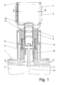
- Fig. 1 shows the essential part of the invention of a Stirling engine. It consists of a base plate (1), in which the supply (E) and discharge (A) of the cooling water are housed and a transmission (2) is mounted, which can be configured as a sine, wobble or Rhombengetriebe. In the gear compartment and a generator can be integrated, but these elements are not relevant to the further explanation of the invention and therefore not shown.
- the transmission operates via the piston rod (11) the working piston (10) and to phase-shifted over the rod (13) the displacer (12).
- On the base plate (1) of the cylinder base (3) is fixed, which includes the cylinder liner and the radiator (5).
- the cylinder head (4) of the regenerator (6) is housed, at its top is made of individual tubes existing heat exchanger (7) grown.
- the heat exchanger (7) establishes a connection between the collecting space of the regenerator (14) and the cylinder expansion space (15).
- the working gas is diverted at the end of the pipe row in the collector (8) in the corresponding pipe groups.
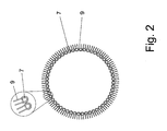
- Fig. 2 shows the cut (SS) Fig. 1 , Clearly visible is the circular arrangement of the row of tubes of the heat exchanger (7).
- U-shaped bent ribs (9) are soldered, the ends of which are directed to the outside and give the heat exchanger as a whole a high heat-conducting surface.
- Fig. 3 shows Stirling engine and heat exchanger in the working position to the firebox of a biomass combustion.
- the exemplified part of the furnace consists of the flame tube (21), the fireclay lining (20), the insulation (19) and the outer jacket plate (18).
- a stop ring (17) ensures that, together with the base plate (1) and the seal (16) a conclusion against the ingress of foreign air is formed in the firing chamber.
- the machine is in the operating state, the hot combustion gases (G) are forcibly passed through the heat exchanger (9) of the Stirling engine and further cooled in the sequence of devices not shown.
- a tubular brush (22) consisting of the bristle holder (23) and the bristles (24).
- the bristles (24) are directed to the cylinder base (3) and the cylinder head (4) and touch these parts only slightly.
- the temperature of the brush (22) of high values in the region of the Feuerschamotts (20) over a longer distance on the cylinder head (4) and the cooled cylinder lower part (3) to values which correspond approximately to the cooling water temperature can degrade.
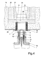
- Fig. 4 shows the device according to the invention in its cleaning position, which also corresponds to the Anterrorism- and rest position.
- the illustration shows the ribs of the heat exchanger (9) in the region of the brush (22).
- the diameter of the heat exchanger (7) with ribs (9) must be greater than the diameter of the cylinder head (4) and the cylinder base (3).
- the cover plate (25) located on the heat exchanger-collecting ring (8) forms with the circular opening in the fireclay lining (21) a sufficiently tight conclusion, so that operation of the heating system can take place without Stirling machine in working position.
- the Stirling engine is moved by means of a suitable drive on a guide. This device is not shown here for the sake of simplicity.
Landscapes
- Engineering & Computer Science (AREA)
- Mechanical Engineering (AREA)
- General Engineering & Computer Science (AREA)
- Chemical & Material Sciences (AREA)
- Combustion & Propulsion (AREA)
- Physics & Mathematics (AREA)
- Thermal Sciences (AREA)
- Geometry (AREA)
- Heat-Exchange Devices With Radiators And Conduit Assemblies (AREA)
Applications Claiming Priority (1)
| Application Number | Priority Date | Filing Date | Title |
|---|---|---|---|
| AT6852007A AT504666B1 (de) | 2007-05-03 | 2007-05-03 | Wärmetauscher |
Publications (2)
| Publication Number | Publication Date |
|---|---|
| EP1988352A2 true EP1988352A2 (fr) | 2008-11-05 |
| EP1988352A3 EP1988352A3 (fr) | 2014-01-15 |
Family
ID=39616313
Family Applications (1)
| Application Number | Title | Priority Date | Filing Date |
|---|---|---|---|
| EP08450062.8A Withdrawn EP1988352A3 (fr) | 2007-05-03 | 2008-04-24 | Echangeur thermique |
Country Status (2)
| Country | Link |
|---|---|
| EP (1) | EP1988352A3 (fr) |
| AT (1) | AT504666B1 (fr) |
Cited By (7)
| Publication number | Priority date | Publication date | Assignee | Title |
|---|---|---|---|---|
| AT513734A1 (de) * | 2012-12-04 | 2014-06-15 | Kofen Forschungs Und Entwicklungsgesellschaft M B H | Heizkessel mit Wärmekraftmaschine |
| EP2511508A4 (fr) * | 2009-12-09 | 2014-10-22 | Estir Co Ltd | Moteur stirling et procédé d'élimination des impuretés dans un groupe de tubes de transfert de chaleur dans un dispositif énergétique ou un dispositif de génération électrique utilisant un moteur stirling |
| EP2868907A1 (fr) | 2013-10-31 | 2015-05-06 | Frauscher Holding Gesellschaft m.b.H. | Échangeur de chaleur pour une machine thermodynamique |
| DE102015120801B3 (de) * | 2015-12-01 | 2017-03-09 | Frauscher Holding Gmbh | Stirling-Motor mit einem Wärmetauscher und Verfahren zur Reinigung eines Wärmetauschers in einem Stirling-Motor |
| EP3425274A1 (fr) * | 2017-07-04 | 2019-01-09 | ÖKOFEN Forschungs- und Entwicklungsgesellschaft m.b.H. | Dispositif de chauffage |
| CN120274565A (zh) * | 2025-05-14 | 2025-07-08 | 云南澄江华业磷化工有限责任公司 | 基于多级交换的黄磷生产余热高效回收利用工艺及装置 |
| DE102024107039A1 (de) * | 2024-03-12 | 2025-09-18 | Frauscher Holding Gmbh | Wärmetauscher für Verbrennungskraftmaschine mit externer Verbrennung |
Families Citing this family (1)
| Publication number | Priority date | Publication date | Assignee | Title |
|---|---|---|---|---|
| AT520068B1 (de) * | 2017-05-16 | 2019-09-15 | Oekofen Forschungs Und Entw M B H | Heizeinrichtung |
Citations (2)
| Publication number | Priority date | Publication date | Assignee | Title |
|---|---|---|---|---|
| JPS5777898A (en) | 1980-11-01 | 1982-05-15 | Kawasaki Heavy Ind Ltd | Cleaning device for heat conducting surface of heat exchanger |
| DE10337312B3 (de) | 2003-08-14 | 2005-01-05 | Fachhochschule Bingen | Erhitzer eines Stirlingmotors |
Family Cites Families (6)
| Publication number | Priority date | Publication date | Assignee | Title |
|---|---|---|---|---|
| US1985156A (en) * | 1932-12-12 | 1934-12-18 | Fred W Fieldhouse | Condenser cleaner |
| DE847525C (de) * | 1950-02-10 | 1952-08-25 | Philips Nv | Heissgaskolbenmaschine |
| US3848412A (en) * | 1970-03-06 | 1974-11-19 | Philips Corp | Method of supplying thermal energy to the heater of a hot-gas engine, as well as a hot-gas engine comprising a device for carrying out the method |
| JPS5847911A (ja) * | 1981-09-16 | 1983-03-19 | Kiichi Taga | 回転ワイヤブラシ式ス−ト除去装置 |
| DE4016238A1 (de) * | 1990-05-19 | 1991-11-21 | Stirling Motors Gmbh | Vorrichtung zur erzeugung elektrischer und heizenergie |
| DE19612616C2 (de) * | 1996-03-29 | 2002-03-07 | Sipra Patent Beteiligung | Stirlingmotor |
-
2007
- 2007-05-03 AT AT6852007A patent/AT504666B1/de not_active IP Right Cessation
-
2008
- 2008-04-24 EP EP08450062.8A patent/EP1988352A3/fr not_active Withdrawn
Patent Citations (2)
| Publication number | Priority date | Publication date | Assignee | Title |
|---|---|---|---|---|
| JPS5777898A (en) | 1980-11-01 | 1982-05-15 | Kawasaki Heavy Ind Ltd | Cleaning device for heat conducting surface of heat exchanger |
| DE10337312B3 (de) | 2003-08-14 | 2005-01-05 | Fachhochschule Bingen | Erhitzer eines Stirlingmotors |
Non-Patent Citations (1)
| Title |
|---|
| BETA" STIRLINGMASCHINEN IST ZUM BEISPIEL IN DEM FACHBAUCH "THE PHILIPS STIRLING ENGINE, pages 144 |
Cited By (12)
| Publication number | Priority date | Publication date | Assignee | Title |
|---|---|---|---|---|
| EP2511508A4 (fr) * | 2009-12-09 | 2014-10-22 | Estir Co Ltd | Moteur stirling et procédé d'élimination des impuretés dans un groupe de tubes de transfert de chaleur dans un dispositif énergétique ou un dispositif de génération électrique utilisant un moteur stirling |
| US9097206B2 (en) | 2009-12-09 | 2015-08-04 | Estir Co., Ltd. | Stirling engine and method of removing impurities in a heat-transfer tube group in a power device or a power-generating device which uses a stirling engine |
| AT513734A1 (de) * | 2012-12-04 | 2014-06-15 | Kofen Forschungs Und Entwicklungsgesellschaft M B H | Heizkessel mit Wärmekraftmaschine |
| EP2741000A3 (fr) * | 2012-12-04 | 2014-08-20 | Ökofen Forschungs- und Entwicklungsges. M.B.H. | Chaudière dotée d'un moteur thermique |
| AT513734B1 (de) * | 2012-12-04 | 2022-12-15 | Oekofen Forschungs Und Entw M B H | Heizkessel mit Wärmekraftmaschine |
| EP2868907A1 (fr) | 2013-10-31 | 2015-05-06 | Frauscher Holding Gesellschaft m.b.H. | Échangeur de chaleur pour une machine thermodynamique |
| DE102015120801B3 (de) * | 2015-12-01 | 2017-03-09 | Frauscher Holding Gmbh | Stirling-Motor mit einem Wärmetauscher und Verfahren zur Reinigung eines Wärmetauschers in einem Stirling-Motor |
| EP3176534A2 (fr) | 2015-12-01 | 2017-06-07 | Frauscher Holding GmbH | Dispositif et procédé de nettoyage d'un échangeur de chaleur |
| EP3425274A1 (fr) * | 2017-07-04 | 2019-01-09 | ÖKOFEN Forschungs- und Entwicklungsgesellschaft m.b.H. | Dispositif de chauffage |
| DE102024107039A1 (de) * | 2024-03-12 | 2025-09-18 | Frauscher Holding Gmbh | Wärmetauscher für Verbrennungskraftmaschine mit externer Verbrennung |
| WO2025191012A1 (fr) | 2024-03-12 | 2025-09-18 | Frauscher Holding Gmbh | Échangeur de chaleur pour un moteur a combustion ayant une combustion externe |
| CN120274565A (zh) * | 2025-05-14 | 2025-07-08 | 云南澄江华业磷化工有限责任公司 | 基于多级交换的黄磷生产余热高效回收利用工艺及装置 |
Also Published As
| Publication number | Publication date |
|---|---|
| AT504666A4 (de) | 2008-07-15 |
| EP1988352A3 (fr) | 2014-01-15 |
| AT504666B1 (de) | 2008-07-15 |
Similar Documents
| Publication | Publication Date | Title |
|---|---|---|
| AT504666B1 (de) | Wärmetauscher | |
| DE60117022T2 (de) | Drainagevorrichtung für die lager einer gasturbine | |
| DE60133268T2 (de) | Thermokinetischer verdichter | |
| EP1692450B1 (fr) | Souffleur de suie compact | |
| WO2022189200A1 (fr) | Système de chauffage de biomasse ayant un dispositif de nettoyage amélioré | |
| EP2373928B1 (fr) | Appareil de nettoyage pour un segment de convection d'une centrale thermique | |
| EP0360052B1 (fr) | Réacteur de pyrolyse pour l'élimination thermique de déchets | |
| DE4409338C2 (de) | Dampferzeuger | |
| EP2549185B1 (fr) | Appareil de nettoyage pour une section de convection d'une centrale thermique | |
| DE654640C (de) | Hochleistungsdampferzeuger mit Zwangdurchlauf des Arbeitsmittels | |
| DE102019215002A1 (de) | Dampferzeuger | |
| DE102009047392B4 (de) | Abgaswärmeübertrager in einem Blockheizkraftwerk | |
| DE1778074A1 (de) | Kessel | |
| DE102010061072B4 (de) | Reinigung eines mit einem Aggregat verbundenen Wärmetauschers | |
| AT520068B1 (de) | Heizeinrichtung | |
| CH270344A (de) | Gasturbinen-Kraftanlage. | |
| EP2535546B1 (fr) | Installation de production combinée de chaleur et d'électricité | |
| AT511485B1 (de) | Dampferzeuger mit einem brennraum, zumindest einem rauchgaskanal und einer kesselbaugruppe | |
| AT503536A1 (de) | Wärmetauscher | |
| DE178196C (fr) | ||
| EP3176534B1 (fr) | Dispositif et procédé de nettoyage d'un échangeur de chaleur | |
| DE694224C (de) | Heizvorrichtung fuer das Schweroel-Luft-Gemisch von Brennkraftmaschinen | |
| WO2000044855A2 (fr) | Systeme d'energie pour le recyclage des huiles usees | |
| DE102021110096A1 (de) | Reinigungsgerät für einen rauchgasführenden Innenbereich einer Verbrennungsanlage | |
| DE2931160A1 (de) | Nachschaltheizflaechenblock |
Legal Events
| Date | Code | Title | Description |
|---|---|---|---|
| PUAI | Public reference made under article 153(3) epc to a published international application that has entered the european phase |
Free format text: ORIGINAL CODE: 0009012 |
|
| AK | Designated contracting states |
Kind code of ref document: A2 Designated state(s): AT BE BG CH CY CZ DE DK EE ES FI FR GB GR HR HU IE IS IT LI LT LU LV MC MT NL NO PL PT RO SE SI SK TR |
|
| AX | Request for extension of the european patent |
Extension state: AL BA MK RS |
|
| RAP1 | Party data changed (applicant data changed or rights of an application transferred) |
Owner name: FRAUSCHER HOLDING GMBH |
|
| RIN1 | Information on inventor provided before grant (corrected) |
Inventor name: FRAUSCHER, JOSEF |
|
| PUAL | Search report despatched |
Free format text: ORIGINAL CODE: 0009013 |
|
| AK | Designated contracting states |
Kind code of ref document: A3 Designated state(s): AT BE BG CH CY CZ DE DK EE ES FI FR GB GR HR HU IE IS IT LI LT LU LV MC MT NL NO PL PT RO SE SI SK TR |
|
| AX | Request for extension of the european patent |
Extension state: AL BA MK RS |
|
| RIC1 | Information provided on ipc code assigned before grant |
Ipc: F28G 1/08 20060101ALI20131212BHEP Ipc: F28G 1/02 20060101ALI20131212BHEP Ipc: F28D 7/08 20060101AFI20131212BHEP Ipc: F02G 1/055 20060101ALI20131212BHEP Ipc: F28F 1/14 20060101ALI20131212BHEP |
|
| 17P | Request for examination filed |
Effective date: 20140715 |
|
| RBV | Designated contracting states (corrected) |
Designated state(s): AT BE BG CH CY CZ DE DK EE ES FI FR GB GR HR HU IE IS IT LI LT LU LV MC MT NL NO PL PT RO SE SI SK TR |
|
| AKX | Designation fees paid |
Designated state(s): AT BE BG CH CY CZ DE DK EE ES FI FR GB GR HR HU IE IS IT LI LT LU LV MC MT NL NO PL PT RO SE SI SK TR |
|
| 17Q | First examination report despatched |
Effective date: 20160707 |
|
| GRAP | Despatch of communication of intention to grant a patent |
Free format text: ORIGINAL CODE: EPIDOSNIGR1 |
|
| INTG | Intention to grant announced |
Effective date: 20170116 |
|
| STAA | Information on the status of an ep patent application or granted ep patent |
Free format text: STATUS: THE APPLICATION IS DEEMED TO BE WITHDRAWN |
|
| 18D | Application deemed to be withdrawn |
Effective date: 20170527 |