EP2002962B1 - Anlage zum Aufheizen der Vorformlinge für das Blasen von Behältern - Google Patents
Anlage zum Aufheizen der Vorformlinge für das Blasen von Behältern Download PDFInfo
- Publication number
- EP2002962B1 EP2002962B1 EP08157861A EP08157861A EP2002962B1 EP 2002962 B1 EP2002962 B1 EP 2002962B1 EP 08157861 A EP08157861 A EP 08157861A EP 08157861 A EP08157861 A EP 08157861A EP 2002962 B1 EP2002962 B1 EP 2002962B1
- Authority
- EP
- European Patent Office
- Prior art keywords
- source
- preforms
- electromagnetic radiation
- path
- bodies
- Prior art date
- Legal status (The legal status is an assumption and is not a legal conclusion. Google has not performed a legal analysis and makes no representation as to the accuracy of the status listed.)
- Active
Links
Images

Classifications
-
- B—PERFORMING OPERATIONS; TRANSPORTING
- B29—WORKING OF PLASTICS; WORKING OF SUBSTANCES IN A PLASTIC STATE IN GENERAL
- B29C—SHAPING OR JOINING OF PLASTICS; SHAPING OF MATERIAL IN A PLASTIC STATE, NOT OTHERWISE PROVIDED FOR; AFTER-TREATMENT OF THE SHAPED PRODUCTS, e.g. REPAIRING
- B29C49/00—Blow-moulding, i.e. blowing a preform or parison to a desired shape within a mould; Apparatus therefor
- B29C49/42—Component parts, details or accessories; Auxiliary operations
- B29C49/64—Heating or cooling preforms, parisons or blown articles
- B29C49/68—Ovens specially adapted for heating preforms or parisons
- B29C49/682—Ovens specially adapted for heating preforms or parisons characterised by the path, e.g. sinusoidal path
-
- B—PERFORMING OPERATIONS; TRANSPORTING
- B29—WORKING OF PLASTICS; WORKING OF SUBSTANCES IN A PLASTIC STATE IN GENERAL
- B29B—PREPARATION OR PRETREATMENT OF THE MATERIAL TO BE SHAPED; MAKING GRANULES OR PREFORMS; RECOVERY OF PLASTICS OR OTHER CONSTITUENTS OF WASTE MATERIAL CONTAINING PLASTICS
- B29B13/00—Conditioning or physical treatment of the material to be shaped
- B29B13/02—Conditioning or physical treatment of the material to be shaped by heating
- B29B13/023—Half-products, e.g. films, plates
- B29B13/024—Hollow bodies, e.g. tubes or profiles
-
- B—PERFORMING OPERATIONS; TRANSPORTING
- B29—WORKING OF PLASTICS; WORKING OF SUBSTANCES IN A PLASTIC STATE IN GENERAL
- B29C—SHAPING OR JOINING OF PLASTICS; SHAPING OF MATERIAL IN A PLASTIC STATE, NOT OTHERWISE PROVIDED FOR; AFTER-TREATMENT OF THE SHAPED PRODUCTS, e.g. REPAIRING
- B29C49/00—Blow-moulding, i.e. blowing a preform or parison to a desired shape within a mould; Apparatus therefor
- B29C49/42—Component parts, details or accessories; Auxiliary operations
- B29C49/64—Heating or cooling preforms, parisons or blown articles
- B29C49/68—Ovens specially adapted for heating preforms or parisons
- B29C49/6835—Ovens specially adapted for heating preforms or parisons using reflectors
-
- B—PERFORMING OPERATIONS; TRANSPORTING
- B29—WORKING OF PLASTICS; WORKING OF SUBSTANCES IN A PLASTIC STATE IN GENERAL
- B29C—SHAPING OR JOINING OF PLASTICS; SHAPING OF MATERIAL IN A PLASTIC STATE, NOT OTHERWISE PROVIDED FOR; AFTER-TREATMENT OF THE SHAPED PRODUCTS, e.g. REPAIRING
- B29C35/00—Heating, cooling or curing, e.g. crosslinking or vulcanising; Apparatus therefor
- B29C35/02—Heating or curing, e.g. crosslinking or vulcanizing during moulding, e.g. in a mould
- B29C35/08—Heating or curing, e.g. crosslinking or vulcanizing during moulding, e.g. in a mould by wave energy or particle radiation
- B29C35/0805—Heating or curing, e.g. crosslinking or vulcanizing during moulding, e.g. in a mould by wave energy or particle radiation using electromagnetic radiation
- B29C2035/0822—Heating or curing, e.g. crosslinking or vulcanizing during moulding, e.g. in a mould by wave energy or particle radiation using electromagnetic radiation using IR radiation
-
- B—PERFORMING OPERATIONS; TRANSPORTING
- B29—WORKING OF PLASTICS; WORKING OF SUBSTANCES IN A PLASTIC STATE IN GENERAL
- B29C—SHAPING OR JOINING OF PLASTICS; SHAPING OF MATERIAL IN A PLASTIC STATE, NOT OTHERWISE PROVIDED FOR; AFTER-TREATMENT OF THE SHAPED PRODUCTS, e.g. REPAIRING
- B29C35/00—Heating, cooling or curing, e.g. crosslinking or vulcanising; Apparatus therefor
- B29C35/02—Heating or curing, e.g. crosslinking or vulcanizing during moulding, e.g. in a mould
- B29C35/08—Heating or curing, e.g. crosslinking or vulcanizing during moulding, e.g. in a mould by wave energy or particle radiation
- B29C35/0805—Heating or curing, e.g. crosslinking or vulcanizing during moulding, e.g. in a mould by wave energy or particle radiation using electromagnetic radiation
- B29C2035/0838—Heating or curing, e.g. crosslinking or vulcanizing during moulding, e.g. in a mould by wave energy or particle radiation using electromagnetic radiation using laser
-
- B—PERFORMING OPERATIONS; TRANSPORTING
- B29—WORKING OF PLASTICS; WORKING OF SUBSTANCES IN A PLASTIC STATE IN GENERAL
- B29C—SHAPING OR JOINING OF PLASTICS; SHAPING OF MATERIAL IN A PLASTIC STATE, NOT OTHERWISE PROVIDED FOR; AFTER-TREATMENT OF THE SHAPED PRODUCTS, e.g. REPAIRING
- B29C2949/00—Indexing scheme relating to blow-moulding
- B29C2949/07—Preforms or parisons characterised by their configuration
- B29C2949/0715—Preforms or parisons characterised by their configuration the preform having one end closed
-
- B—PERFORMING OPERATIONS; TRANSPORTING
- B29—WORKING OF PLASTICS; WORKING OF SUBSTANCES IN A PLASTIC STATE IN GENERAL
- B29C—SHAPING OR JOINING OF PLASTICS; SHAPING OF MATERIAL IN A PLASTIC STATE, NOT OTHERWISE PROVIDED FOR; AFTER-TREATMENT OF THE SHAPED PRODUCTS, e.g. REPAIRING
- B29C49/00—Blow-moulding, i.e. blowing a preform or parison to a desired shape within a mould; Apparatus therefor
- B29C49/02—Combined blow-moulding and manufacture of the preform or the parison
- B29C49/06—Injection blow-moulding
-
- B—PERFORMING OPERATIONS; TRANSPORTING
- B29—WORKING OF PLASTICS; WORKING OF SUBSTANCES IN A PLASTIC STATE IN GENERAL
- B29C—SHAPING OR JOINING OF PLASTICS; SHAPING OF MATERIAL IN A PLASTIC STATE, NOT OTHERWISE PROVIDED FOR; AFTER-TREATMENT OF THE SHAPED PRODUCTS, e.g. REPAIRING
- B29C49/00—Blow-moulding, i.e. blowing a preform or parison to a desired shape within a mould; Apparatus therefor
- B29C49/42—Component parts, details or accessories; Auxiliary operations
- B29C49/64—Heating or cooling preforms, parisons or blown articles
- B29C49/6409—Thermal conditioning of preforms
- B29C49/6418—Heating of preforms
-
- B—PERFORMING OPERATIONS; TRANSPORTING
- B29—WORKING OF PLASTICS; WORKING OF SUBSTANCES IN A PLASTIC STATE IN GENERAL
- B29C—SHAPING OR JOINING OF PLASTICS; SHAPING OF MATERIAL IN A PLASTIC STATE, NOT OTHERWISE PROVIDED FOR; AFTER-TREATMENT OF THE SHAPED PRODUCTS, e.g. REPAIRING
- B29C49/00—Blow-moulding, i.e. blowing a preform or parison to a desired shape within a mould; Apparatus therefor
- B29C49/42—Component parts, details or accessories; Auxiliary operations
- B29C49/64—Heating or cooling preforms, parisons or blown articles
- B29C49/6409—Thermal conditioning of preforms
- B29C49/6436—Thermal conditioning of preforms characterised by temperature differential
- B29C49/6445—Thermal conditioning of preforms characterised by temperature differential through the preform length
-
- B—PERFORMING OPERATIONS; TRANSPORTING
- B29—WORKING OF PLASTICS; WORKING OF SUBSTANCES IN A PLASTIC STATE IN GENERAL
- B29C—SHAPING OR JOINING OF PLASTICS; SHAPING OF MATERIAL IN A PLASTIC STATE, NOT OTHERWISE PROVIDED FOR; AFTER-TREATMENT OF THE SHAPED PRODUCTS, e.g. REPAIRING
- B29C49/00—Blow-moulding, i.e. blowing a preform or parison to a desired shape within a mould; Apparatus therefor
- B29C49/42—Component parts, details or accessories; Auxiliary operations
- B29C49/64—Heating or cooling preforms, parisons or blown articles
- B29C49/68—Ovens specially adapted for heating preforms or parisons
- B29C49/685—Rotating the preform in relation to heating means
-
- B—PERFORMING OPERATIONS; TRANSPORTING
- B29—WORKING OF PLASTICS; WORKING OF SUBSTANCES IN A PLASTIC STATE IN GENERAL
- B29K—INDEXING SCHEME ASSOCIATED WITH SUBCLASSES B29B, B29C OR B29D, RELATING TO MOULDING MATERIALS OR TO MATERIALS FOR MOULDS, REINFORCEMENTS, FILLERS OR PREFORMED PARTS, e.g. INSERTS
- B29K2067/00—Use of polyesters or derivatives thereof, as moulding material
Definitions
- the present invention relates generally to the manufacture of containers made of thermoplastic material such as PET by blow molding or stretch-blow molding of preforms, and more particularly to heating installations of preform bodies of thermoplastic material, with a view to blow-molding or stretch-blow molding, while said preforms are moved so that their respective bodies follow a predetermined path, these heating installations comprising at least one source of infrared electromagnetic radiation disposed laterally to the trajectory followed by the body of the preforms and directed to a location of said trajectory, a reflector being disposed on the other side of the path opposite to that where is disposed the source of electromagnetic radiation.
- Thermoplastic container manufacturing plants include, for heating preforms prior to the blow molding or stretch-blow molding stage, heating installations, for example of the tunnel furnace type, which are conventionally equipped with incandescent lamps with infrared radiation. .
- the or each source of coherent infrared electromagnetic radiation is directed substantially perpendicular to the path followed by the bodies of the preforms.
- Such an arrangement certainly gives satisfaction for the heating of the bodies of the preforms, particularly as regards the selectivity of this heating when such selectivity is sought, but it also has drawbacks.
- a disadvantage of this known arrangement is that the radiation passes through each body by heating the material thereof, but is not completely absorbed.
- the fraction of the radiation that has not been absorbed is reflected by a reflector disposed opposite the source and is returned to the bodies of the preforms and sources.
- this reflection is accompanied by partial absorption and heating of the reflector, resulting in a loss of energy.
- the efficiency of such a heating arrangement is not optimum.
- part of the reflected fraction of the radiation can return to the source, which is detrimental to the life of the latter.
- the or each source of coherent infrared electromagnetic radiation is directed substantially along the path followed by the bodies of the preforms, so that the radiation passes successively through a plurality of consecutive preform bodies.
- Such an arrangement certainly gives satisfaction for the heating, as such, the bodies of the preforms and the yield can be considered better than that of the previous solution.
- this known arrangement has a disadvantage inherent in that the trajectory of the bodies of the preforms must be deviated from the source just upstream thereof, ie the carrier moving the preforms must make an elbow in front of the source.
- the absorption of the electromagnetic radiation is more or less important, and an installation in the distance between the radiation sources is fixed does not allow to deal with a good performance a large number of types of preforms made of thermoplastic materials of different characteristics and with different behaviors.
- the carrier of the preforms must have as many deflection means (bends and / or transfer wheels) to deviate at each times the trajectory of the bodies of the preforms.
- deflection means baffles and / or transfer wheels
- Such a transfer of the preforms on a sinuous path is doubly penalizing, on the one hand because the carrier becomes complex and expensive and on the other hand because the presence of the sinuosities does not allow to scroll the preforms at speeds too high that it might be desired.
- the aim of the invention is to propose an improved technical solution which avoids, as far as possible, the disadvantages presented by the solutions already known and which notably allows the use of infrared electromagnetic radiation for the purpose of heating the bodies.
- thermoplastic preforms with improved efficiency and without risk to the source of electromagnetic radiation, these advantages must in addition be obtainable without significant additional cost of the installation.
- thermoplastic preform bodies as defined by claim 1.
- the electromagnetic radiation is not reflected or is only slightly reflected towards said source of electromagnetic radiation or to a nearby source of electromagnetic radiation: the reflected radiation will then reach the source laterally by striking the active part thereof (in particular the front face thereof) under a low incidence and almost grazing, without that can result in significant damage to the source.
- the angular range mentioned makes it possible to ensure that, by an appropriate choice of the angle ⁇ as a function of the diameter of the preforms and of their spacing pitch on the conveyor, at least a major part of the radiation reaches permanently on at least one preform body and / or one or more preform body parts.
- the interval defined between the bodies of two successive preforms, seen from the source remains low, or preferably is zero, so that at most a small portion of the radiation can pass between the consecutive preforms and reaches the reflector arranged on the opposite wall.
- said angle is less than about 45 °.
- the totality of the electromagnetic radiation emitted by the directional source is desirable for the totality of the electromagnetic radiation emitted by the directional source to be able to reach at least one body of preforms or several body parts of preforms irrespective of the relative positions. preforms scrolling with respect to the source. This condition will be more easily satisfied for a larger number of sizes of medium or large diameter preforms and various spacing steps of successive preforms if the directive source of electromagnetic radiation is inclined at an angle of between about 20 ° and 31 ° C. ° with respect to the tangent to said trajectory at said location.
- the trajectory followed by the bodies of the preforms may be curvilinear to said location, and it is then desirable for the directive source of electromagnetic radiation to be disposed on the convex side of said trajectory.
- the most common configuration in practice is that the path followed by the bodies of the preforms is substantially rectilinear to said location, and the directive source of electromagnetic radiation can then be arranged indifferently on one side or the other of said trajectory.
- the directive source of electromagnetic radiation is directed against the direction of movement of the preforms, or more generally that the directive source of electromagnetic radiation is instead directed in the direction of movement of the preforms.
- an interesting mode of exploitation may consist in combining these two provisions and in predicting that the installation comprises at least two directive sources of electromagnetic radiation, that at least one directive source of electromagnetic radiation is directed in the direction of displacement of the preforms and that at least one other directive source of electromagnetic radiation, located downstream of the previous, is in turn directed against the direction of movement of the preforms: thus, in an example of application of this provision which can then be implemented at the outlet of the furnace, it is possible to provide a final thermal pulse at a predetermined location of the body or part of the body of the preform at the moment when it leaves the heating installation and immediately before its introduction into the blowing installation, so that the body of the preform can be deformed under optimal conditions including in its difficult deformation zones.
- the directive source of electromagnetic radiation is substantially monochromatic (or almost monochromatic, that is to say covering a narrow window of electromagnetic frequencies), the radiation can also advantageously be collimated .
- said directive source of electromagnetic radiation may be a laser source, and in particular a laser diode.
- several diodes can be grouped to form a source direction of form and extent appropriate to the needs.
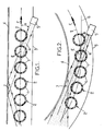
- the figure 1 it is represented, in a very schematic form and in plan view, only a part, necessary for the understanding of the invention, of a heating system of the bodies 1 of preforms 2 of thermoplastic material, for the purpose of manufacture of containers by a blowing or stretch-blow molding process.
- the preforms 2 are moved by a suitable conveyor (not shown), so that their respective bodies 1 follow a predetermined path T.
- the direction of movement of the preforms 2 is indicated by the arrow F.
- the heating installation is generally in the form of at least one tunnel furnace laterally bordered by two side walls, designated respectively by the references 3 and 4 to the figure 1 .
- FIG. 1 To the figure 1 is illustrated by way of example a conventional configuration, and generally implemented, a tunnel furnace which consists in that the tunnel furnace is rectilinear at least in part and that the trajectory T of displacement of the preforms 2 is rectilinear in this portion of the oven.
- the heating installation comprises at least one source 5 of infrared electromagnetic radiation which is a directional source disposed laterally to the trajectory T followed by the bodies 1 of the preforms 2 and directed towards a location E of the trajectory T followed by the bodies 1 of the preforms 2.
- the infrared electromagnetic R radiation emitted by the direction source 5 can be substantially monochromatic (or almost monochromatic, that is to say covering a narrow window of electromagnetic frequencies), the radiation can also be advantageously collimated.
- the directional source is supported by one of the walls of the furnace, for example the wall 3, and on the other side of the path T a reflector 7 extends at least at the location of the opposite wall 4 where the propagation direction of the radiation R reaches said wall 4.
- the electromagnetic radiation directive source is inclined at an angle ⁇ between about 60 ° and 10 ° with respect to the tangent 6 at said path T at said location E, so that the electromagnetic radiation can not be reflected or is only slightly reflected towards the source 5 of electromagnetic radiation or a neighboring source; the reflected radiation then arrives laterally on the source, but reaches the active part thereof (that is to say the front face thereof) only under a low incidence and almost grazing: the source can not then undergo significant damage or heating that could disrupt its proper operation.
- the mentioned angular range makes it possible to ensure that, by an appropriate choice of the angle ⁇ in As a function of the diameter of the preforms and their spacing pitch on the conveyor, at least a major part of the radiation permanently reaches at least one preform body or several body parts of preforms.
- the interval defined between the bodies of two successive preforms, seen from the source remains low, or preferably is zero, so that at most a small portion of the radiation can pass between the consecutive preforms and reach the reflector arranged on the opposite wall.
- the bodies or body parts of the successive preforms will intercept the entire radiation electromagnetic, while, in the case of the treatment of preforms having a mean diameter (for example a diameter of an order of magnitude of about 20 mm), a fraction of the radiation can certainly pass through the free interval defined between two consecutive preforms, but it is then a relatively small fraction of the radiation and it does not result in a significant disadvantage.
- a fraction of the radiation can certainly pass through the free interval defined between two consecutive preforms, but it is then a relatively small fraction of the radiation and it does not result in a significant disadvantage.
- the angle ⁇ remains less than about 45 °, so that the electromagnetic radiation can not be reflected, even partially, to the source 5 of electromagnetic radiation or a neighboring source; in other words, the electromagnetic radiation can not be reflected towards the active part (ie towards the front face) of the source 5 of electromagnetic radiation or a neighboring source, the radiation reflected by the reflector 7 being able to reach source 5 or another source laterally by striking the casing or casing thereof without damage to the actual active part of the source.
- all of the electromagnetic radiation emitted by the directional source can permanently reach at least one preform body or several preform body parts regardless of the relative positions. preforms scrolling with respect to the source. This condition will be more easily satisfied for a larger number of preform sizes of medium or large diameters (for example diameters varying around an order of magnitude of about 20 to 45 mm) and various spacing steps of the preforms. successive if the directive source of electromagnetic radiation is inclined at an angle of between about 20 ° and 31 ° with respect to the tangent to said path to said location.
- the preforms are spaced from each other with a pitch of 40 mm or 50 mm; the installations arranged with a pitch of 40 mm can accept preforms which, according to the models, have bodies having diameters of between approximately 19 and 36 mm; the installations arranged with a pitch of 50 mm can accept preforms which, depending on the model, have bodies having diameters of between approximately 19 and 43 mm. It will then be ensured that all of the electromagnetic radiation emitted by a directional source permanently reaches a body or preform body parts if the angle ⁇ is, as mentioned above, between about 20 ° and 31 °.
- the electromagnetic radiation directive source 5 can be arranged indifferently on one side or the other of the trajectory T, in other words the direction source can be supported by the wall 4 and the reflection means be supported by the wall 3 , depending on the installation requirements of the installation; it is also conceivable to mount several directive sources on both walls 3, 4 at the same time, taking care that each directive source does not receive incident or reflected radiation from one or more other sources.
- the electromagnetic radiation directive source is inclined of the aforesaid angle ⁇ with respect to the tangent 6 to said trajectory T at the location E.
- the heating installation is then assumed to include a curvilinear tunnel furnace whose side walls 3, 4 are curvilinear.
- the reflector means supported by the wall 4 are, in the representation adopted at the figure 2 , of the convex reflector type.
- the electromagnetic radiation directive source it is advantageous for the electromagnetic radiation directive source to be disposed on the convex side of the trajectory T so as to be assured that it receives no reflected radiation.
- the electromagnetic radiation directive source on the concave side of the trajectory T.
- the reflector means also become of the concave reflector type and the radiation is reflected in the form of a widely divergent beam. . It is then more complicated, from a structural point of view, to ensure that all or part of this reflected radiation does not reach the source 5 or a source 5, the difficulty being further increased in the case of implantation. of several sources staggered along the trajectory T.
- the source or sources 5b directives directed in the opposite direction to the direction of displacement of the preforms makes it possible to finalize the additional thermal input just at the moment where the preforms reach the outlet S of the furnace and are grasped by the transfer means which will bring them to the respective molds, in other words very shortly before they are introduced into the respective molds.
- the electromagnetic radiation directive source may be a laser source, typically in the form of at least one laser diode which is small in size and is nowadays commonly available.
- the electromagnetic radiation may be shaped in any appropriate manner depending on the application and the result to be obtained, in particular according to the extent, position and shape of the zone to be heated on the bodies of the preforms.
- the electromagnetic radiation beam may advantageously be collimated to form an edge beam substantially parallels as shown by way of example to the figure 1 , or be divergent as shown by way of example at the figure 2 .
- heating means arranged according to the invention can give rise to various design variants of the heating system. It can thus be envisaged that the entire heating installation is constituted with directional sources arranged in accordance with the invention. However, since the currently available reference sources are laser sources that are relatively expensive, it is conceivable that only one or more parts of the heating installation may be constituted in accordance with the invention, while the rest of the installation remains equipped with less expensive traditional lamps; In particular, provision can be made to equip the end portion, adjacent to the outlet, of the heating installation in accordance with the invention as has been explained above.
- source is meant to designate not only the actual emitter of radiation, but also, if applicable, all the organs and ancillary devices that may be associated with the emitter to generate the desired shaped radiation at the required location on the wall 3 of the furnace (eg collimator device, optical conduit such as optical fiber (s) to project the radiation to the desired location while the transmitter is positioned apart, ).
- organs and ancillary devices that may be associated with the emitter to generate the desired shaped radiation at the required location on the wall 3 of the furnace (eg collimator device, optical conduit such as optical fiber (s) to project the radiation to the desired location while the transmitter is positioned apart, .
Landscapes
- Physics & Mathematics (AREA)
- Thermal Sciences (AREA)
- Engineering & Computer Science (AREA)
- Mechanical Engineering (AREA)
- Manufacturing & Machinery (AREA)
- Blow-Moulding Or Thermoforming Of Plastics Or The Like (AREA)
- Heating, Cooling, Or Curing Plastics Or The Like In General (AREA)
- Processing And Handling Of Plastics And Other Materials For Molding In General (AREA)
Claims (12)
- Aufheizvorrichtung für Körper (1) von Vorformlingen (2) aus thermoplastischem Material im Hinblick auf die Herstellung von Behältern über Blasziehen oder Streck-Blasziehen, während die Vorformlinge (2) auf eine Weise bewegt werden, dass ihre Körper (1) jeweils einer festgesetzten Trajektorie (T) folgen, wobei die Trajektorie zumindest abschnittsweise gerade oder abschnittsweise gekrümmt ist, die Aufheizvorrichtung mindestens eine Quelle (5) elektromagnetischer Infrarotstrahlung umfasst, die seitlich von der Trajektorie, der die Körper (1) der Vorformlinge (2) folgen, angeordnet und in Richtung einer Stelle (E) der Trajektorie (T) ausgerichtet ist und wobei ein Reflektor (7) auf der anderen Seite der Trajektorie (T) angeordnet ist, die der der Quelle (5) elektromagnetischer Strahlung gegenüberliegt,
dadurch gekennzeichnet, dass der Reflektor (7) ein zu der Trajektorie (T) korrespondierendes Profil aufweist und dadurch, dass die Quelle (5) elektromagnetischer Infrarotstrahlung eine gerichtete Quelle ist, die um einen Winkel (α) zwischen ungefähr 60° und 10° zur Tangente (6) hin zum Reflektor (7) geneigt ist. - Aufheizvorrichtung gemäß Anspruch 1, dadurch gekennzeichnet, dass der Winkel (α) kleiner als ungefähr 45° ist.
- Aufheizvorrichtung gemäß Anspruch 2, dadurch gekennzeichnet, dass der Winkel (α) zwischen ungefähr 20° und 31° ist.
- Aufheizvorrichtung gemäß Anspruch 2, dadurch gekennzeichnet, dass der Winkel (α) zwischen ungefähr 12° und 20° ist.
- Aufheizvorrichtung gemäß einem der Ansprüche 1 bis 4, dadurch gekennzeichnet, dass die von den Körpern (1) der Vorformlinge (2) gefolgte Trajektorie (T) im Wesentlichen geradlinig zu der Stelle (E) ist und dadurch, dass die gerichtete Quelle (5) elektromagnetischer Strahlung willkürlich auf der einen oder anderen Seite der Trajektorie (T) angeordnet sein kann.
- Aufheizvorrichtung gemäß einem der Ansprüche 1 bis 4, dadurch gekennzeichnet, dass die von den Körpern (1) der Vorformlinge (2) gefolgte Trajektorie (T) zu der Stelle (E) bogenförmig ist.
- Aufheizvorrichtung gemäß Anspruch 6, dadurch gekennzeichnet, dass die gerichtete Quelle (5) elektromagnetischer Strahlung auf der konvexen Seite der Trajektorie (T) angeordnet ist.
- Aufheizvorrichtung gemäß einem der Ansprüche 1 bis 7, dadurch gekennzeichnet, dass die gerichtete Quelle (5) elektromagnetischer Strahlung in der Richtung (F) der Bewegung der Vorformlinge (2) ausgerichtet ist.
- Aufheizvorrichtung gemäß einem der Ansprüche 1 bis 7, dadurch gekennzeichnet, dass die gerichtete Quelle (5) elektromagnetischer Strahlung entgegen der Richtung (F) der Bewegung der Vorformlinge (2) ausgerichtet ist.
- Aufheizvorrichtung gemäß einem der Ansprüche 8 und 9, dadurch gekennzeichnet, dass sie mindestens zwei gerichtete Quellen (5) elektromagnetischer Strahlung umfasst, dadurch, dass mindestens eine gerichtete Quelle (5a) elektromagnetischer Strahlung in der Richtung (F) der Bewegung der Vorformlinge (2) ausgerichtet ist und dadurch, dass mindestens eine gerichtete Quelle (5b) elektromagnetischer Strahlung, die ablaufseitig zu der vorigen angeordnet ist, entgegen der Richtung (F) der Bewegung der Vorformlinge (2) ausgerichtet ist.
- Aufheizvorrichtung gemäß einem der Ansprüche 1 bis 10, dadurch gekennzeichnet, dass die gerichtete Quelle (5) elektromagnetischer Strahlung eine Laserquelle ist.
- Aufheizvorrichtung gemäß Anspruch 11, dadurch gekennzeichnet, dass die gerichtete Quelle (5) elektromagnetischer Strahlung ein Diodenlaser ist.
Applications Claiming Priority (1)
| Application Number | Priority Date | Filing Date | Title |
|---|---|---|---|
| FR0704144A FR2917005B1 (fr) | 2007-06-11 | 2007-06-11 | Installation de chauffage des corps de preformes pour le soufflage de recipients |
Publications (2)
| Publication Number | Publication Date |
|---|---|
| EP2002962A1 EP2002962A1 (de) | 2008-12-17 |
| EP2002962B1 true EP2002962B1 (de) | 2011-08-17 |
Family
ID=39060217
Family Applications (1)
| Application Number | Title | Priority Date | Filing Date |
|---|---|---|---|
| EP08157861A Active EP2002962B1 (de) | 2007-06-11 | 2008-06-09 | Anlage zum Aufheizen der Vorformlinge für das Blasen von Behältern |
Country Status (8)
| Country | Link |
|---|---|
| US (1) | US8662876B2 (de) |
| EP (1) | EP2002962B1 (de) |
| JP (1) | JP4768780B2 (de) |
| CN (1) | CN101323170B (de) |
| AT (1) | ATE520517T1 (de) |
| ES (1) | ES2371949T3 (de) |
| FR (1) | FR2917005B1 (de) |
| MX (1) | MX2008007509A (de) |
Families Citing this family (13)
| Publication number | Priority date | Publication date | Assignee | Title |
|---|---|---|---|---|
| FR2913210B1 (fr) | 2007-03-02 | 2009-05-29 | Sidel Participations | Perfectionnements a la chauffe des matieres plastiques par rayonnement infrarouge |
| EP2421690B1 (de) * | 2009-04-21 | 2018-03-21 | Koninklijke Philips N.V. | Heizsystem und verfahren zum heizen eines vorformlingkörpers |
| BR112012005508A2 (pt) | 2009-09-15 | 2019-09-24 | Koninklijke Philips Electrnics N. V. | método de aquecimento de uma pré forma, disposição de direcionamento para controlar a unidade de geração de radiação laser de um sistema de aqueicmento de pré forma sistema de aquecimento de pré forma, particulamente um aparelho para sopro de frasco, para aquecimento de uma pré forma e programa de computador para aquecimento de uma pré forma |
| FR2957294B1 (fr) * | 2010-03-10 | 2012-04-20 | Sidel Participations | Unite de traitement d'ebauches de corps creux par rayonnement, equipee d'un sas de confinement du rayonnement |
| FR2964901B1 (fr) * | 2010-09-20 | 2012-10-26 | Sidel Participations | Procede de formage d'un recipient par chauffe laser selective et soufflage libre. |
| IT1402342B1 (it) * | 2010-10-12 | 2013-08-30 | Sipa Progettazione Automaz | Dispositivo di riscaldamento di preforme in materiale termoplastico. |
| FR2976841B1 (fr) * | 2011-06-23 | 2013-08-02 | Sidel Participations | Procede de chauffe d'une ebauche de recipient a faible temperature de paroi externe |
| FR2982790B1 (fr) | 2011-11-21 | 2014-03-14 | Sidel Participations | Unite de traitement thermique d'ebauches de recipients a double paroi rayonnante en quinconce |
| ITMI20121855A1 (it) * | 2012-10-31 | 2014-05-01 | Smi Spa | Sistema di riscaldamento per forno per preforme |
| FR3094663A1 (fr) * | 2019-04-04 | 2020-10-09 | Sidel Participations | Procédé d’orientation d’une préforme |
| US12280396B2 (en) | 2019-04-19 | 2025-04-22 | Photex Inc. | Narrowband can manufacturing |
| MX2021012817A (es) * | 2019-04-19 | 2022-03-04 | Photex Inc | Sistema y metodo para curar el interior de la lata. |
| IT202100008870A1 (it) * | 2021-04-09 | 2022-10-09 | Smi Spa | Sistema di riscaldamento delle preforme |
Family Cites Families (211)
| Publication number | Priority date | Publication date | Assignee | Title |
|---|---|---|---|---|
| US2769117A (en) | 1952-07-01 | 1956-10-30 | Pirillo Santo | Ozone producing device |
| US3309553A (en) * | 1963-08-16 | 1967-03-14 | Varian Associates | Solid state radiation emitters |
| US4720480A (en) | 1985-02-28 | 1988-01-19 | Dai Nippon Insatsu Kabushiki Kaisha | Sheet for heat transference |
| US5260258A (en) | 1985-02-28 | 1993-11-09 | Dai Nippon Insatsu Kabushiki Kaisha | Sheet for heat transference |
| US5270285A (en) | 1965-02-28 | 1993-12-14 | Dai Nippon Insatsu Kabushiki Kaisha | Sheet for heat transference |
| JPS61237691A (ja) * | 1985-04-15 | 1986-10-22 | Dainippon Printing Co Ltd | 被熱転写シ−ト |
| US3640671A (en) * | 1969-02-26 | 1972-02-08 | Monsanto Co | Apparatus for venting and releasing plastic articles from a blow mold |
| US3626143A (en) | 1969-04-02 | 1971-12-07 | American Can Co | Scoring of materials with laser energy |
| US3627989A (en) | 1969-12-11 | 1971-12-14 | Thermal Quarr Schmelze Gmbh | Infrared surface heater |
| US3768314A (en) | 1972-01-20 | 1973-10-30 | Stewart Warner Corp | Modular gauge housing |
| US3950459A (en) * | 1972-12-27 | 1976-04-13 | Phillips Petroleum Company | Continuous process for producing, reheating, and blow molding parisons |
| CH580687A5 (de) * | 1973-08-22 | 1976-10-15 | Spirig Ernst | |
| US4050887A (en) | 1973-11-21 | 1977-09-27 | Monsanto Company | Method and apparatus for temperature conditioning parts |
| JPS5739932B2 (de) | 1974-02-14 | 1982-08-24 | ||
| US4020232A (en) * | 1974-05-17 | 1977-04-26 | Mitsubishi Paper Mills, Ltd. | Heat-sensitive recording sheets |
| US3974016A (en) | 1974-11-04 | 1976-08-10 | Bell Telephone Laboratories, Incorporated | Bonding of thermoplastic coated cylinders |
| US4058699A (en) | 1975-08-01 | 1977-11-15 | Arthur D. Little, Inc. | Radiant zone heating apparatus and method |
| US4224096A (en) | 1976-03-25 | 1980-09-23 | W. R. Grace & Co. | Laser sealing of thermoplastic material |
| US4079104A (en) * | 1976-04-16 | 1978-03-14 | Owens-Illinois, Inc. | Method for heating plastic articles |
| US4135077A (en) * | 1976-09-16 | 1979-01-16 | Wills Kendall S | Laser bread browning apparatus |
| US4097715A (en) * | 1977-05-16 | 1978-06-27 | General Refractories Company | Laser jet bell kiln |
| US4204111A (en) * | 1977-10-19 | 1980-05-20 | Monsanto Company | Heating improvements in a preform reheat system |
| US4234297A (en) | 1978-03-14 | 1980-11-18 | Owens-Illinois, Inc. | Apparatus for blow molding |
| US4163238A (en) | 1978-06-09 | 1979-07-31 | The United States Of America As Represented By The Secretary Of The Army | Infrared semiconductor device with superlattice region |
| US4304978A (en) | 1978-10-05 | 1981-12-08 | Coherent, Inc. | Heat treating using a laser |
| US4331858A (en) * | 1980-02-14 | 1982-05-25 | Pet Incorporated | Open hearth oven |
| US4313720A (en) * | 1980-03-03 | 1982-02-02 | Emhart Industries, Inc. | Parison transfer means |
| US4338114A (en) | 1980-08-21 | 1982-07-06 | Liberty Glass Company | Laser treatment method for imparting increased mechanical strength to glass objects |
| DE3210676C2 (de) | 1981-03-30 | 1984-12-06 | Cincinnati Milacron Industries, Inc., Cincinnati, Ohio | Verfahen zum Strahlungserwärmen von Vorformlingen |
| US4374678A (en) * | 1981-06-01 | 1983-02-22 | Texas Instruments Incorporated | Process for forming HgCoTe alloys selectively by IR illumination |
| US4409455A (en) | 1982-03-05 | 1983-10-11 | Cincinnati Milacron Inc. | Dielectric heating section for blow molding machine |
| US4456811A (en) * | 1982-06-21 | 1984-06-26 | Avco Everett Research Laboratory, Inc. | Method of and apparatus for heat treating axisymmetric surfaces with an annular laser beam |
| US4486639A (en) | 1982-07-19 | 1984-12-04 | Control Data Corporation | Microwave oven quartz lamp heaters |
| US4459458A (en) | 1982-08-30 | 1984-07-10 | The Warner & Swasey Company | Machine tool with laser heat treating |
| US4507538A (en) * | 1982-10-22 | 1985-03-26 | Mostek Corporation | Laser hardening with selective shielding |
| US4481405A (en) | 1983-04-27 | 1984-11-06 | Malick Franklin S | Cooking appliance |
| DE3339613A1 (de) | 1983-11-02 | 1985-05-09 | Vdo Adolf Schindling Ag, 6000 Frankfurt | Anzeigeeinheit |
| FR2561986B1 (fr) | 1984-03-28 | 1986-09-26 | Pont A Mousson | Dispositif de chauffage d'ebauches en materiau thermoplastique en vue de former, par soufflage, des corps creux |
| IT1179063B (it) * | 1984-08-20 | 1987-09-16 | Fiat Auto Spa | Apparecchiatura per effettuare trattamenti su pezzi metallici mediante laser di potenza |
| NL8402659A (nl) * | 1984-08-31 | 1986-03-17 | Optische Ind De Oude Delft Nv | Werkwijze en inrichting voor het justeren van de gelijkloop van een vizierinrichting en een zwenkbaar orgaan. |
| FR2571201B1 (fr) | 1984-10-02 | 1987-01-02 | Valeo | Procede de chauffage dans la masse d'une substance par exemple en vue d'une vulcanisation ou d'une polymerisation |
| GB2165493A (en) | 1984-10-16 | 1986-04-16 | Aeci Ltd | Keyboard |
| US4672169A (en) * | 1985-03-21 | 1987-06-09 | Standard Oil Company (Indiana) | Apparatus and method for heating materials with a laser heat source |
| DE3518204C1 (de) | 1985-05-21 | 1986-10-16 | Adam Opel AG, 6090 Rüsselsheim | Armaturentafel |
| JPS6237350A (ja) | 1985-08-12 | 1987-02-18 | Toshiba Corp | 表面熱処理装置 |
| US4816694A (en) * | 1985-08-15 | 1989-03-28 | Sanders Associates, Inc. | Radiation system |
| US4754141A (en) * | 1985-08-22 | 1988-06-28 | High Technology Sensors, Inc. | Modulated infrared source |
| US4810092A (en) * | 1986-02-21 | 1989-03-07 | Midac Corporation | Economical spectrometer unit having simplified structure |
| JPH074986B2 (ja) * | 1986-05-26 | 1995-01-25 | 富士写真フイルム株式会社 | 感熱記録材料 |
| JPH0717102B2 (ja) * | 1986-10-08 | 1995-03-01 | 富士写真フイルム株式会社 | 感熱記録材料 |
| DE3781259D1 (de) | 1986-12-25 | 1992-09-24 | Fuji Photo Film Co Ltd | Verfahren zur herstellung eines waermeempfindlichen aufzeichnungsmaterials. |
| DE3721289A1 (de) * | 1987-06-27 | 1989-01-12 | Opel Adam Ag | Armaturentafel fuer fahrzeuge, insbesondere kraftfahrzeuge |
| DE3860748D1 (de) | 1987-09-03 | 1990-11-08 | Berstorff Gmbh Masch Hermann | Einrichtung zum drehbaren transportieren von vorformlingen durch eine aufheizstation zu einer streckblasmaschine. |
| JPH0741742B2 (ja) | 1987-10-02 | 1995-05-10 | 富士写真フイルム株式会社 | 感熱記録材料 |
| GB2210702B (en) * | 1987-10-02 | 1991-11-06 | Fuji Photo Film Co Ltd | Heat sensitive recording material |
| JPH06104385B2 (ja) * | 1987-12-01 | 1994-12-21 | 富士写真フイルム株式会社 | 感熱記録材料 |
| LU87192A1 (de) | 1988-04-07 | 1989-11-14 | Euratom | Vorrichtung zum herstellen amorpher keramikstoffe oder metallegierungen |
| US5883362A (en) * | 1988-05-19 | 1999-03-16 | Quadlux, Inc. | Apparatus and method for regulating cooking time in a lightwave oven |
| US4900891A (en) * | 1988-06-20 | 1990-02-13 | Roger Vega | Laser ice removal system |
| US5260715A (en) | 1988-06-28 | 1993-11-09 | Fuji Photo Film Co., Ltd. | Method of and apparatus for thermally recording image on a transparent heat sensitive material |
| US4989791A (en) * | 1988-07-01 | 1991-02-05 | Ridenour Ralph Gaylord | Valve nozzle assembly |
| DE3826841A1 (de) * | 1988-08-06 | 1990-02-08 | Berstorff Gmbh Masch Hermann | Einrichtung zum gleichmaessigen und schnellen aufheizen von sich drehenden vorformlingen fuer nach den streckblasverfahren hergestellte hohlkoerper |
| US4894509A (en) * | 1988-12-13 | 1990-01-16 | International Business Machines Corporation | Laser assisted heater bar for multiple lead attachment |
| US4948937A (en) | 1988-12-23 | 1990-08-14 | Itt Corporation | Apparatus and method for heat cleaning semiconductor material |
| EP0387737B1 (de) | 1989-03-14 | 1993-08-11 | BEKUM Maschinenfabriken GmbH | Verfahren zur Erhitzung von einem Vorrat entnommenen gespritzten Vorformlingen für das anschliessende Aufblasen zu Hohlkörpern in einer Blasform und Vorrichtung zum Blasformen vorgefertigter Vorformlinge |
| GB2230740B (en) | 1989-04-04 | 1993-09-29 | Apple Computer | Modular keyboard |
| NL8901257A (nl) * | 1989-05-19 | 1990-12-17 | Leeuwarder Papier | Werkwijze voor het aanbrengen van verzwakkingslijnen in resp. het graveren van kunststofmateriaal, in het bijzonder verpakkingsmateriaal. |
| JPH0373814A (ja) * | 1989-08-15 | 1991-03-28 | Jujo Paper Co Ltd | 光出力、主波長識別方法 |
| US5010659A (en) * | 1989-09-08 | 1991-04-30 | W. R. Grace & Co.-Conn. | Infrared drying system |
| US6638413B1 (en) | 1989-10-10 | 2003-10-28 | Lectro Press, Inc. | Methods and apparatus for electrolysis of water |
| EP0431808A3 (en) | 1989-12-08 | 1992-05-20 | Tokyo Electric Co., Ltd. | Tag printer |
| US5154512A (en) | 1990-04-10 | 1992-10-13 | Luxtron Corporation | Non-contact techniques for measuring temperature or radiation-heated objects |
| US5160556A (en) | 1990-08-22 | 1992-11-03 | United Container Machinery Group, Inc. | Method of hardening corrugating rolls |
| AU650865B2 (en) * | 1990-09-07 | 1994-07-07 | Caterpillar Inc. | Adaptive vehicle display |
| WO1992005026A1 (en) | 1990-09-13 | 1992-04-02 | Wellstar Holding B.V. | Preform for polyester bottle |
| JPH04280915A (ja) * | 1991-01-10 | 1992-10-06 | Nippon Steel Corp | 金属線材のレーザ熱処理法およびその装置 |
| JP3132840B2 (ja) | 1991-03-22 | 2001-02-05 | コニカ株式会社 | 感熱転写記録用受像シートおよび感熱転写記録方法 |
| FR2678542B1 (fr) | 1991-07-01 | 1993-10-29 | Sidel | Procede et installation pour le chauffage, par rayonnement infrarouge, de preformes en matiere plastique, notamment en pet, destinees a la fabrication de recipients. |
| US5261415A (en) | 1991-07-12 | 1993-11-16 | Ciba Corning Diagnostics Corp. | CO2 mainstream capnography sensor |
| US5163179A (en) | 1991-07-18 | 1992-11-10 | The United States Of America As Represented By The Secretary Of The Air Force | Platinum silicide infrared diode |
| US5206039A (en) * | 1991-09-24 | 1993-04-27 | Valyi Emery I | Apparatus for conditioning pressure molded plastic articles |
| US5267959A (en) * | 1991-11-29 | 1993-12-07 | Schneider, Inc. | Laser bonding of angioplasty balloon catheters |
| US5349211A (en) | 1992-03-26 | 1994-09-20 | Nec Corporation | Semiconductor infrared emitting device with oblique side surface with respect to the cleavage |
| FR2689442B1 (fr) * | 1992-04-03 | 1995-06-23 | Sidel Sa | Procede de conditionnement thermique de preformes en matieres thermoplastiques et dispositif pour la mise en óoeuvre de ce procede. |
| FR2691401B1 (fr) * | 1992-05-20 | 1994-08-05 | Sidel Sa | Unite pour le traitement thermique de recipients en pet lors de la fabrication de ceux-ci. |
| ATE157927T1 (de) * | 1992-07-07 | 1997-09-15 | Continental Pet Technologies | Verfahren zum formen von einem behälter mit einer seitenwand von hoher kristallinität und einem boden von niedriger kristallinität |
| DE4234342C2 (de) | 1992-10-12 | 1998-05-14 | Fraunhofer Ges Forschung | Verfahren zur Materialbearbeitung mit Laserstrahlung |
| FR2700293B1 (fr) * | 1993-01-08 | 1995-03-24 | Settembrini Antoine Di | Machine de fabrication de corps creux par soufflage. |
| FR2703944B1 (fr) * | 1993-04-15 | 1995-06-23 | Sidel Sa | Procédé et installation pour le traitement thermique du corps d'une préforme en matériau thermoplastique. |
| US5382441A (en) * | 1993-04-16 | 1995-01-17 | The Pillsbury Company | Method of processing food utilizing infrared radiation |
| JP2914847B2 (ja) * | 1993-07-09 | 1999-07-05 | 株式会社東芝 | 半導体レーザ装置 |
| US5457299A (en) | 1993-10-29 | 1995-10-10 | International Business Machines Corporation | Semiconductor chip packaging method which heat cures an encapsulant deposited on a chip using a laser beam to heat the back side of the chip |
| US5394492A (en) * | 1993-11-19 | 1995-02-28 | Applied Optronics Corporation | High power semiconductor laser system |
| US5509733A (en) * | 1993-12-21 | 1996-04-23 | Ta Instruments, Inc. | Infrared heated differential thermal analyzer |
| US6450941B1 (en) | 1994-01-21 | 2002-09-17 | Eric Larsen | Device for the stimulation of body cells through electromagnetic radiation |
| JP2920904B2 (ja) | 1994-03-28 | 1999-07-19 | 矢崎総業株式会社 | メータモジュール組立体 |
| DE69506053T2 (de) | 1994-07-22 | 1999-05-20 | Fujicopian Co., Ltd., Osaka | Thermotransferaufzeichnungsmaterial |
| DE4429913C1 (de) * | 1994-08-23 | 1996-03-21 | Fraunhofer Ges Forschung | Vorrichtung und Verfahren zum Plattieren |
| JP2954858B2 (ja) | 1994-09-16 | 1999-09-27 | 日精エー・エス・ビー機械株式会社 | 射出延伸ブロー成形装置及び方法 |
| US5698866A (en) | 1994-09-19 | 1997-12-16 | Pdt Systems, Inc. | Uniform illuminator for phototherapy |
| IL111428A (en) * | 1994-10-27 | 1997-07-13 | Supercom Ltd | Laminated plastic cards and process and apparatus for making them |
| FR2732924B1 (fr) * | 1995-04-12 | 1997-06-13 | Sidel Sa | Procede et dispositif de chauffage selectif d'une preforme de recipient |
| US5565119A (en) | 1995-04-28 | 1996-10-15 | International Business Machines Corporation | Method and apparatus for soldering with a multiple tip and associated optical fiber heating device |
| US5553391A (en) * | 1995-06-05 | 1996-09-10 | Bakalar; Sharon F. | Method and apparatus for heat treating webs |
| JPH08337065A (ja) * | 1995-06-13 | 1996-12-24 | Fujicopian Co Ltd | 熱転写記録材料 |
| US5888644A (en) * | 1995-07-17 | 1999-03-30 | Fujicopian Co., Ltd. | Thermal transfer recording material |
| US5589210A (en) | 1995-08-23 | 1996-12-31 | Centro De Investigacion Y De Estudios-Avanzados Del I.P.N. | Method for cooking wheat flour products by using infrared radiation |
| US5740314A (en) * | 1995-08-25 | 1998-04-14 | Edison Welding Institute | IR heating lamp array with reflectors modified by removal of segments thereof |
| US5964749A (en) * | 1995-09-15 | 1999-10-12 | Esc Medical Systems Ltd. | Method and apparatus for skin rejuvenation and wrinkle smoothing |
| US5618489A (en) * | 1995-10-05 | 1997-04-08 | Hoover Universal, Inc. | Apparatus and process for blow molding containers |
| JPH0999644A (ja) * | 1995-10-09 | 1997-04-15 | Fujicopian Co Ltd | 熱転写記録材料 |
| JPH09142031A (ja) | 1995-11-22 | 1997-06-03 | Fujicopian Co Ltd | 熱転写記録材料 |
| CH690095A5 (fr) * | 1995-12-07 | 2000-04-28 | Tetra Pak Plastics Ltd Tetra P | Dispositif de chauffage pour machines de transformation de matières plastiques. |
| JPH09240319A (ja) | 1995-12-28 | 1997-09-16 | Yazaki Corp | 電装モジュールの組付け構造 |
| DE19603974B4 (de) | 1996-01-26 | 2004-05-19 | Udo Prof. Dr.-Ing. Hellwig | Verfahren zum Verformen von Körpern und Materialbahnen |
| JP3672678B2 (ja) | 1996-04-05 | 2005-07-20 | 富士通株式会社 | 量子半導体装置およびその製造方法 |
| US5780524A (en) | 1996-05-14 | 1998-07-14 | Olsen; Don E. | Micro heating apparatus for synthetic fibers and related methods |
| GB2315450B (en) | 1996-07-20 | 2000-10-11 | Mckechnie Plastics Ltd | Improved method and apparatus for shaping thermoplastic tubes |
| US5759200A (en) * | 1996-09-04 | 1998-06-02 | Azar; Zion | Method of selective photothermolysis |
| US5976288A (en) | 1997-01-10 | 1999-11-02 | Ekendahl; Lars O. | Method of forming a molded, multi-layer structure |
| JP3760045B2 (ja) | 1997-02-17 | 2006-03-29 | 日精エー・エス・ビー機械株式会社 | 耐熱容器の成形方法 |
| US6151338A (en) | 1997-02-19 | 2000-11-21 | Sdl, Inc. | High power laser optical amplifier system |
| US5820820A (en) | 1997-04-18 | 1998-10-13 | Pierce; Brian N. | Method of thermally and selectively separating water and or solvents from solids under vacuum utilizing radiant heat |
| US5925710A (en) | 1997-04-23 | 1999-07-20 | Hoechst Celanese Corporation | Infrared absorbing polyester packaging polymer |
| DE19815276B4 (de) | 1997-05-02 | 2010-04-08 | C.A. Greiner & Söhne Ges.m.b.H. | Nachbehandlungsverfahren für einen extrudierten Gegenstand |
| US5865546A (en) * | 1997-08-29 | 1999-02-02 | Compaq Computer Corporation | Modular keyboard for use in a computer system |
| US6815206B2 (en) | 1997-09-19 | 2004-11-09 | Ethicon, Inc. | Container monitoring system |
| US5834313A (en) * | 1997-09-19 | 1998-11-10 | Johnson & Johnson Medical, Inc. | Container monitoring system |
| US5953356A (en) | 1997-11-04 | 1999-09-14 | Wisconsin Alumni Research Foundation | Intersubband quantum box semiconductor laser |
| US6482672B1 (en) | 1997-11-06 | 2002-11-19 | Essential Research, Inc. | Using a critical composition grading technique to deposit InGaAs epitaxial layers on InP substrates |
| DE19750263A1 (de) | 1997-11-13 | 1999-05-20 | Iwk Verpackungstechnik Gmbh | Verfahren und Vorrichtung zum Verschließen einer Kunststoff-Tube in einer Tubenfüllmaschine |
| US5981611A (en) | 1997-11-24 | 1999-11-09 | Prince Corporation | Thermoformable foam with infrared receptors |
| US6246935B1 (en) | 1997-12-01 | 2001-06-12 | Daimlerchrysler Corporation | Vehicle instrument panel computer interface and display |
| US6069345A (en) * | 1997-12-11 | 2000-05-30 | Quadlux, Inc. | Apparatus and method for cooking food with a controlled spectrum |
| US6104604A (en) | 1998-01-06 | 2000-08-15 | Gateway 2000, Inc. | Modular keyboard |
| US20030161917A1 (en) * | 1998-01-20 | 2003-08-28 | Ernest A. Voisin | Process of elimination of bacteria in shellfish of shucking shellfish and an apparatus therefor |
| US6022920A (en) * | 1998-01-23 | 2000-02-08 | Eastman Chemical Company | Method for the production of clear bottles having improved reheat |
| US6080146A (en) | 1998-02-24 | 2000-06-27 | Altshuler; Gregory | Method and apparatus for hair removal |
| US6503586B1 (en) * | 1998-02-25 | 2003-01-07 | Arteva North America S.A.R.L. | Title improved infrared absorbing polyester packaging polymer |
| US6243035B1 (en) | 1998-02-27 | 2001-06-05 | Universal Electronics Inc. | Key module for wireless keyboard |
| US6038786A (en) * | 1998-04-16 | 2000-03-21 | Excel Dryer Inc. | Hand dryer |
| US6146677A (en) | 1998-05-01 | 2000-11-14 | Remco Techologies, Inc. | High efficiency infrared oven |
| JP3268443B2 (ja) | 1998-09-11 | 2002-03-25 | 科学技術振興事業団 | レーザ加熱装置 |
| US20040056006A1 (en) * | 1998-10-01 | 2004-03-25 | The Welding Institute | Welding method |
| FR2785564B1 (fr) | 1998-11-10 | 2000-12-08 | Cebal | Traitement de materiaux au laser, notamment de decoupage ou de soudure |
| US6507042B1 (en) * | 1998-12-25 | 2003-01-14 | Fujitsu Limited | Semiconductor device and method of manufacturing the same |
| DE19901540A1 (de) | 1999-01-16 | 2000-07-20 | Philips Corp Intellectual Pty | Verfahren zur Feinabstimmung eines passiven, elektronischen Bauelementes |
| DE29900811U1 (de) | 1999-01-19 | 1999-03-18 | Sator Laser GmbH, 22525 Hamburg | Vorrichtung zum Verschweißen des Endes von rohrartigen Behältern aus Kunststoff, insbesondere von Tuben |
| US6428735B1 (en) * | 1999-02-26 | 2002-08-06 | Schmalbach-Lubeca Ag | Method for making a carbonated soft drink bottle with an internal web and hand-grip feature |
| US6174388B1 (en) * | 1999-03-15 | 2001-01-16 | Lockheed Martin Energy Research Corp. | Rapid infrared heating of a surface |
| JP2002542079A (ja) * | 1999-04-23 | 2002-12-10 | デュースターヘフト・カルステン | 物体を非切削成形する自動化方法と装置 |
| DE19919191A1 (de) | 1999-04-29 | 2000-11-02 | Bielomatik Leuze & Co | Verfahren und Vorrichtung zum Schweißen |
| WO2000066346A1 (en) * | 1999-04-30 | 2000-11-09 | Powerlasers Limited | Welding of carpet to panels |
| US6294769B1 (en) | 1999-05-12 | 2001-09-25 | Mccarter David | Infrared food warming device |
| US6357504B1 (en) * | 1999-07-29 | 2002-03-19 | Owens Corning Fiberglas Technology, Inc. | Technology for attaching facing system to insulation product |
| US6441510B1 (en) | 1999-08-17 | 2002-08-27 | Lear Corporation | Reconfigurable modular instrument cluster arrangement |
| EP1242229B1 (de) | 1999-12-03 | 2004-02-18 | Siemens Aktiengesellschaft | Verfahren zum berührungslosen biegen von teilen aus einem thermoplastischen kunststoff und nach diesem verfahren gebogenes oder justiertes teil |
| ES2200460T3 (es) | 1999-12-23 | 2004-03-01 | Leister Process Technologies | Procedimiento y dispositivo para el calentamiento de por lo menos dos elementos mediante rayos laser con elevada densidad de energia. |
| US6361301B1 (en) * | 2000-02-21 | 2002-03-26 | Plastipak Packaging, Inc. | Heater assembly for blow molding plastic preforms |
| US6451152B1 (en) | 2000-05-24 | 2002-09-17 | The Boeing Company | Method for heating and controlling temperature of composite material during automated placement |
| AU2001271484A1 (en) | 2000-06-20 | 2002-01-02 | Morris S. Cohen | Notebook computer keyboard system |
| DE20018500U1 (de) | 2000-10-28 | 2001-12-13 | KRONES AG, 93073 Neutraubling | Blasmaschine |
| JP3516233B2 (ja) * | 2000-11-06 | 2004-04-05 | 日本板硝子株式会社 | 情報記録媒体用ガラス基板の製造方法 |
| WO2002042023A1 (en) | 2000-11-27 | 2002-05-30 | National University Of Singapore | Method and apparatus for creating a three-dimensional metal part using high-temperature direct laser melting |
| US7015422B2 (en) * | 2000-12-21 | 2006-03-21 | Mattson Technology, Inc. | System and process for heating semiconductor wafers by optimizing absorption of electromagnetic energy |
| AUPR245001A0 (en) | 2001-01-10 | 2001-02-01 | Silverbrook Research Pty Ltd | A method (WSM03) |
| CA2332190A1 (en) | 2001-01-25 | 2002-07-25 | Efos Inc. | Addressable semiconductor array light source for localized radiation delivery |
| DE10106607A1 (de) | 2001-02-13 | 2002-09-12 | Carsten Duesterhoeft | Laserstrahlbasiertes Erwärmverfahren und Vorrichtung zur Erzeugung einer genauen orts- und zeitabhängigen Temperaturverteilung auf thermoplastischem Rohmaterial zur Umformung in einer Form |
| US7060942B2 (en) | 2001-04-11 | 2006-06-13 | Hardt Equipment Manufacturing Inc. | Cooking apparatus and method therefor |
| US7009140B2 (en) * | 2001-04-18 | 2006-03-07 | Cymer, Inc. | Laser thin film poly-silicon annealing optical system |
| JP2003011734A (ja) | 2001-04-26 | 2003-01-15 | Denso Corp | 車両用電気機器取付構造 |
| GB0110447D0 (en) * | 2001-04-28 | 2001-06-20 | Genevac Ltd | Improvements in and relating to the heating of microtitre well plates in centrifugal evaporators |
| JP2004529359A (ja) | 2001-05-21 | 2004-09-24 | プレスコ テクノロジー インコーポレーテッド | 自動化されたプロセス制御物品検査アプリケーションの中でスナップショット動作熱赤外線イメージングを提供するための装置および方法 |
| US6670570B2 (en) | 2001-06-15 | 2003-12-30 | L'air Liquide - Societe Anonyme A Directoire Et Couseil De Surveillance Pour L'etude Et L'exploitation Des Procedes Georges Claude | Methods and apparatus for localized heating of metallic and non-metallic surfaces |
| DE10131620B4 (de) | 2001-06-29 | 2007-10-25 | Adphos Advanced Photonics Technologies Ag | Verfahren und Vorrichtung zum Trocknen und/oder Vernetzen oder Erwärmen mittels elektromagnetischer Strahlung |
| DE10145456A1 (de) | 2001-09-14 | 2003-05-22 | Krones Ag | Vorrichtung zum Erwärmen von mit einem Tragring versehenen Vorformlingen |
| DE10149934A1 (de) | 2001-10-10 | 2003-04-17 | Kraft Maschb Gmbh | Verfahren zum Herstellen von Oberflächen dreidimensionaler Formteile |
| EP1302735B1 (de) * | 2001-10-10 | 2014-01-01 | Heidelberger Druckmaschinen Aktiengesellschaft | Vorrichtung und Verfahren zur Zuführung von Strahlungsenergie auf einen Bedruckstoff in einer Flachdruckmaschine |
| AU2002367397A1 (en) * | 2001-12-27 | 2003-07-24 | Palomar Medical Technologies, Inc. | Method and apparatus for improved vascular related treatment |
| DE10246198A1 (de) | 2002-10-01 | 2004-04-22 | Jenoptik Automatisierungstechnik Gmbh | Anordnung zum Schweißen mittels Laserstrahlung |
| FR2848495B1 (fr) * | 2002-12-12 | 2006-11-17 | Sidel Sa | Four pour chauffer au defile des ebauches de recipients en materiau thermoplastique |
| US6710281B1 (en) * | 2002-12-20 | 2004-03-23 | Duane H. Wachnuk | Laser based heat exchanger |
| FR2848906B1 (fr) * | 2002-12-23 | 2006-08-18 | Sidel Sa | Procede et installation de fabrication d'un recipient en matiere plastique |
| DE10307121A1 (de) * | 2003-02-19 | 2004-09-02 | Rodenstock Gmbh | Neutralfarbener photochromer Kunststoffgegenstand |
| GB0305052D0 (en) | 2003-03-05 | 2003-04-09 | Rooney Jonathan P | Modular control panel assembly |
| US6892927B2 (en) * | 2003-04-24 | 2005-05-17 | Intel Corporation | Method and apparatus for bonding a wire to a bond pad on a device |
| US7307243B2 (en) | 2003-05-09 | 2007-12-11 | North Carolina State University | Dynamic radiant food preparation methods and systems |
| US7155876B2 (en) * | 2003-05-23 | 2007-01-02 | Douglas Machine, Inc. | Heat tunnel for film shrinking |
| US7063820B2 (en) | 2003-06-16 | 2006-06-20 | University Of Florida Research Foundation, Inc. | Photoelectrochemical air disinfection |
| US7823366B2 (en) * | 2003-10-07 | 2010-11-02 | Douglas Machine, Inc. | Apparatus and method for selective processing of materials with radiant energy |
| FR2863931B1 (fr) | 2003-12-19 | 2006-03-10 | Sidel Sa | Module de chauffage d'une preforme equipe d'un deflecteur d'air profile de facon aerodynamique et four comportant au moins un tel module |
| FR2863932B1 (fr) | 2003-12-19 | 2007-07-06 | Sidel Sa | Four de chauffage d'une preforme equipe de deux ventilateurs de refroidissement |
| US7220378B2 (en) | 2004-01-07 | 2007-05-22 | Pressco Technology Inc. | Method and apparatus for the measurement and control of both the inside and outside surface temperature of thermoplastic preforms during stretch blow molding operations |
| US20050161866A1 (en) | 2004-01-23 | 2005-07-28 | Rajnish Batlaw | Process of making two-stage injection stretch blow molded polypropylene articles |
| FR2871403B1 (fr) | 2004-06-15 | 2007-11-23 | Sidel Sas | Circuit de refroidissement perfectionne pour un four a preformes et procede de mise en oeuvre d'un tel circuit |
| FR2872734B1 (fr) | 2004-07-08 | 2008-02-22 | Sidel Sa Sa | Four de chauffage d'une preforme comportant un organe de commande du deplacement d'un moyen de chauffage entre des positions indexees |
| US7259131B2 (en) * | 2004-07-20 | 2007-08-21 | Unilever Home & Personal Care Usa, Division Of Conopco, Inc. | Mild, moisturizing cleansing compositions |
| US20070284788A1 (en) | 2004-07-29 | 2007-12-13 | Mitsui Chemicals, Inc. | Process for Producing Hollow Molded Product of Thermoplastic Resin |
| US20060048881A1 (en) * | 2004-09-08 | 2006-03-09 | Evans Richard B | Laser-assisted placement of veiled composite material |
| GB2418094B (en) * | 2004-09-10 | 2010-05-12 | Medicsight Plc | User interface for CT scan analysis |
| FR2876943B1 (fr) * | 2004-10-22 | 2008-08-15 | Sidel Sas | Procede et dispositif de chauffage d'ebauches en matiere thermoplastique |
| FR2878185B1 (fr) * | 2004-11-22 | 2008-11-07 | Sidel Sas | Procede de fabrication de recipients comprenant une etape de chauffe au moyen d'un faisceau de rayonnement electromagnetique coherent |
| EP1662546A1 (de) | 2004-11-25 | 2006-05-31 | The European Community, represented by the European Commission | Induktiv gekoppelte Plasmabearbeitungsvorrichtung |
| US10687391B2 (en) * | 2004-12-03 | 2020-06-16 | Pressco Ip Llc | Method and system for digital narrowband, wavelength specific cooking, curing, food preparation, and processing |
| US7425296B2 (en) | 2004-12-03 | 2008-09-16 | Pressco Technology Inc. | Method and system for wavelength specific thermal irradiation and treatment |
| US10857722B2 (en) * | 2004-12-03 | 2020-12-08 | Pressco Ip Llc | Method and system for laser-based, wavelength specific infrared irradiation treatment |
| US20070188023A1 (en) | 2006-02-10 | 2007-08-16 | Visteon Global Technologies, Inc. | Modular building block instrument cluster |
| FR2907684B1 (fr) * | 2006-10-26 | 2009-12-04 | Sidel Participations | Procede de sterilisation d'une preforme, installation et four pour la fabrication de recipients steriles selon ce procede. |
| FR2915418B1 (fr) * | 2007-04-25 | 2012-11-16 | Sidel Participations | Procede de chauffe d'ebauches pour la fabrication de recipients |
| CN103624966B (zh) * | 2007-06-08 | 2018-01-19 | 普瑞斯克技术公司 | 一种用于特定波长热照射和处理的方法和系统 |
| FR2976514B1 (fr) * | 2011-06-17 | 2013-07-12 | Sidel Participations | Procede de chauffe d'ebauches de recipients |
-
2007
- 2007-06-11 FR FR0704144A patent/FR2917005B1/fr not_active Expired - Fee Related
-
2008
- 2008-06-09 EP EP08157861A patent/EP2002962B1/de active Active
- 2008-06-09 ES ES08157861T patent/ES2371949T3/es active Active
- 2008-06-09 AT AT08157861T patent/ATE520517T1/de not_active IP Right Cessation
- 2008-06-10 CN CN2008101428904A patent/CN101323170B/zh active Active
- 2008-06-10 US US12/136,200 patent/US8662876B2/en not_active Expired - Fee Related
- 2008-06-11 JP JP2008152387A patent/JP4768780B2/ja not_active Expired - Fee Related
- 2008-06-11 MX MX2008007509A patent/MX2008007509A/es active IP Right Grant
Also Published As
| Publication number | Publication date |
|---|---|
| JP2009051198A (ja) | 2009-03-12 |
| CN101323170A (zh) | 2008-12-17 |
| FR2917005B1 (fr) | 2009-08-28 |
| ATE520517T1 (de) | 2011-09-15 |
| US8662876B2 (en) | 2014-03-04 |
| CN101323170B (zh) | 2010-06-02 |
| MX2008007509A (es) | 2009-03-04 |
| ES2371949T3 (es) | 2012-01-11 |
| JP4768780B2 (ja) | 2011-09-07 |
| FR2917005A1 (fr) | 2008-12-12 |
| US20080305203A1 (en) | 2008-12-11 |
| EP2002962A1 (de) | 2008-12-17 |
Similar Documents
| Publication | Publication Date | Title |
|---|---|---|
| EP2002962B1 (de) | Anlage zum Aufheizen der Vorformlinge für das Blasen von Behältern | |
| EP1881263B1 (de) | Vorrichtung zur Beleuchtung oder Signalisierung, die eine gewölbte Lichtleiterplatte umfasst | |
| EP2901075B1 (de) | Lichtleiter für eine beleuchtungs- und/oder signalisierungsvorrichtung eines kraftfahrzeugs | |
| EP3538832B1 (de) | Wärmetauscher | |
| EP1666787B1 (de) | Beleuchtungseinrichtung für Kraftfahrzeugscheinwerfer | |
| EP3232118A1 (de) | Scheinwerfer für ein kraftfahrzeug | |
| CN105074520A (zh) | 光波导 | |
| EP2085488A1 (de) | Device for blowing gas onto a surface of a material in running strips | |
| EP2690349A1 (de) | Lichtwellenleiter für eine Beleuchtungs- und/oder Signalisierungsvorrichtung eines Kraftfahrzeugs | |
| EP2101202A1 (de) | Lichtsignalvorrichtung für Fahrrad | |
| WO1996032243A1 (fr) | Procede et dispositif de chauffage selectif d'une preforme de recipient | |
| FR2823688A1 (fr) | Dispositif de fusion de matiere par faisceau laser | |
| EP1726479A2 (de) | Beleuchtungs- oder Signaleinrichtung für Kraftfahrzeuge | |
| FR2943613A1 (fr) | Cycle et feu arriere pour un cycle | |
| EP0329604A1 (de) | Verfahren und Vorrichtung zum Härten von gleichförmigen Elementen, die in regelmässigen Abständen auf einem Träger befestigt sind | |
| WO2016066908A1 (fr) | Module optique compact pour véhicule | |
| WO2010010241A9 (fr) | Procede de fabrication d'un dispositif par soudage laser avec une portion de surface d'un element formant lentille; dispositif, element de ce dispositif et raccord | |
| WO2015140424A1 (fr) | Unité de traitement d'ébauches équipée d'une section de confinement optique à parois convergentes | |
| BE1023609B1 (fr) | Nez de lance de soufflage | |
| FR2566691A1 (fr) | Procede d'usinage d'un reseau de prefragmentation et generateur d'eclats pour charge militaire explosive | |
| FR3129122A1 (fr) | Module lumineux avec fonctions d’éclairage et de signalisation | |
| EP1506072A1 (de) | Laserschweisskopf und laserschweissvorrichtung | |
| EP0403369A1 (de) | Beleuchtungseinrichtung für eine zylindrische Lichtquelle | |
| BE1023582B1 (fr) | Nez de lance de soufflage | |
| FR2751093A1 (fr) | Dispositif emetteur/reflecteur de rayonnements electromagnetiques, appareil et procede mettant en oeuvre un tel dispositif |
Legal Events
| Date | Code | Title | Description |
|---|---|---|---|
| PUAI | Public reference made under article 153(3) epc to a published international application that has entered the european phase |
Free format text: ORIGINAL CODE: 0009012 |
|
| AK | Designated contracting states |
Kind code of ref document: A1 Designated state(s): AT BE BG CH CY CZ DE DK EE ES FI FR GB GR HR HU IE IS IT LI LT LU LV MC MT NL NO PL PT RO SE SI SK TR |
|
| AX | Request for extension of the european patent |
Extension state: AL BA MK RS |
|
| 17P | Request for examination filed |
Effective date: 20090420 |
|
| 17Q | First examination report despatched |
Effective date: 20090706 |
|
| GRAP | Despatch of communication of intention to grant a patent |
Free format text: ORIGINAL CODE: EPIDOSNIGR1 |
|
| GRAS | Grant fee paid |
Free format text: ORIGINAL CODE: EPIDOSNIGR3 |
|
| GRAA | (expected) grant |
Free format text: ORIGINAL CODE: 0009210 |
|
| AK | Designated contracting states |
Kind code of ref document: B1 Designated state(s): AT BE BG CH CY CZ DE DK EE ES FI FR GB GR HR HU IE IS IT LI LT LU LV MC MT NL NO PL PT RO SE SI SK TR |
|
| REG | Reference to a national code |
Ref country code: GB Ref legal event code: FG4D Free format text: NOT ENGLISH |
|
| REG | Reference to a national code |
Ref country code: CH Ref legal event code: EP |
|
| REG | Reference to a national code |
Ref country code: IE Ref legal event code: FG4D Free format text: LANGUAGE OF EP DOCUMENT: FRENCH |
|
| REG | Reference to a national code |
Ref country code: DE Ref legal event code: R096 Ref document number: 602008008887 Country of ref document: DE Effective date: 20111020 |
|
| REG | Reference to a national code |
Ref country code: NL Ref legal event code: T3 |
|
| REG | Reference to a national code |
Ref country code: ES Ref legal event code: FG2A Ref document number: 2371949 Country of ref document: ES Kind code of ref document: T3 Effective date: 20120111 |
|
| LTIE | Lt: invalidation of european patent or patent extension |
Effective date: 20110817 |
|
| PG25 | Lapsed in a contracting state [announced via postgrant information from national office to epo] |
Ref country code: PT Free format text: LAPSE BECAUSE OF FAILURE TO SUBMIT A TRANSLATION OF THE DESCRIPTION OR TO PAY THE FEE WITHIN THE PRESCRIBED TIME-LIMIT Effective date: 20111219 Ref country code: LT Free format text: LAPSE BECAUSE OF FAILURE TO SUBMIT A TRANSLATION OF THE DESCRIPTION OR TO PAY THE FEE WITHIN THE PRESCRIBED TIME-LIMIT Effective date: 20110817 Ref country code: NO Free format text: LAPSE BECAUSE OF FAILURE TO SUBMIT A TRANSLATION OF THE DESCRIPTION OR TO PAY THE FEE WITHIN THE PRESCRIBED TIME-LIMIT Effective date: 20111117 Ref country code: FI Free format text: LAPSE BECAUSE OF FAILURE TO SUBMIT A TRANSLATION OF THE DESCRIPTION OR TO PAY THE FEE WITHIN THE PRESCRIBED TIME-LIMIT Effective date: 20110817 Ref country code: IS Free format text: LAPSE BECAUSE OF FAILURE TO SUBMIT A TRANSLATION OF THE DESCRIPTION OR TO PAY THE FEE WITHIN THE PRESCRIBED TIME-LIMIT Effective date: 20111217 Ref country code: SE Free format text: LAPSE BECAUSE OF FAILURE TO SUBMIT A TRANSLATION OF THE DESCRIPTION OR TO PAY THE FEE WITHIN THE PRESCRIBED TIME-LIMIT Effective date: 20110817 |
|
| REG | Reference to a national code |
Ref country code: AT Ref legal event code: MK05 Ref document number: 520517 Country of ref document: AT Kind code of ref document: T Effective date: 20110817 |
|
| PG25 | Lapsed in a contracting state [announced via postgrant information from national office to epo] |
Ref country code: LV Free format text: LAPSE BECAUSE OF FAILURE TO SUBMIT A TRANSLATION OF THE DESCRIPTION OR TO PAY THE FEE WITHIN THE PRESCRIBED TIME-LIMIT Effective date: 20110817 Ref country code: CY Free format text: LAPSE BECAUSE OF FAILURE TO SUBMIT A TRANSLATION OF THE DESCRIPTION OR TO PAY THE FEE WITHIN THE PRESCRIBED TIME-LIMIT Effective date: 20110817 Ref country code: GR Free format text: LAPSE BECAUSE OF FAILURE TO SUBMIT A TRANSLATION OF THE DESCRIPTION OR TO PAY THE FEE WITHIN THE PRESCRIBED TIME-LIMIT Effective date: 20111118 Ref country code: AT Free format text: LAPSE BECAUSE OF FAILURE TO SUBMIT A TRANSLATION OF THE DESCRIPTION OR TO PAY THE FEE WITHIN THE PRESCRIBED TIME-LIMIT Effective date: 20110817 Ref country code: SI Free format text: LAPSE BECAUSE OF FAILURE TO SUBMIT A TRANSLATION OF THE DESCRIPTION OR TO PAY THE FEE WITHIN THE PRESCRIBED TIME-LIMIT Effective date: 20110817 Ref country code: PL Free format text: LAPSE BECAUSE OF FAILURE TO SUBMIT A TRANSLATION OF THE DESCRIPTION OR TO PAY THE FEE WITHIN THE PRESCRIBED TIME-LIMIT Effective date: 20110817 |
|
| REG | Reference to a national code |
Ref country code: IE Ref legal event code: FD4D |
|
| PG25 | Lapsed in a contracting state [announced via postgrant information from national office to epo] |
Ref country code: SK Free format text: LAPSE BECAUSE OF FAILURE TO SUBMIT A TRANSLATION OF THE DESCRIPTION OR TO PAY THE FEE WITHIN THE PRESCRIBED TIME-LIMIT Effective date: 20110817 Ref country code: CZ Free format text: LAPSE BECAUSE OF FAILURE TO SUBMIT A TRANSLATION OF THE DESCRIPTION OR TO PAY THE FEE WITHIN THE PRESCRIBED TIME-LIMIT Effective date: 20110817 Ref country code: IE Free format text: LAPSE BECAUSE OF FAILURE TO SUBMIT A TRANSLATION OF THE DESCRIPTION OR TO PAY THE FEE WITHIN THE PRESCRIBED TIME-LIMIT Effective date: 20110817 |
|
| PG25 | Lapsed in a contracting state [announced via postgrant information from national office to epo] |
Ref country code: EE Free format text: LAPSE BECAUSE OF FAILURE TO SUBMIT A TRANSLATION OF THE DESCRIPTION OR TO PAY THE FEE WITHIN THE PRESCRIBED TIME-LIMIT Effective date: 20110817 Ref country code: RO Free format text: LAPSE BECAUSE OF FAILURE TO SUBMIT A TRANSLATION OF THE DESCRIPTION OR TO PAY THE FEE WITHIN THE PRESCRIBED TIME-LIMIT Effective date: 20110817 |
|
| PLBE | No opposition filed within time limit |
Free format text: ORIGINAL CODE: 0009261 |
|
| STAA | Information on the status of an ep patent application or granted ep patent |
Free format text: STATUS: NO OPPOSITION FILED WITHIN TIME LIMIT |
|
| PG25 | Lapsed in a contracting state [announced via postgrant information from national office to epo] |
Ref country code: DK Free format text: LAPSE BECAUSE OF FAILURE TO SUBMIT A TRANSLATION OF THE DESCRIPTION OR TO PAY THE FEE WITHIN THE PRESCRIBED TIME-LIMIT Effective date: 20110817 |
|
| 26N | No opposition filed |
Effective date: 20120521 |
|
| PG25 | Lapsed in a contracting state [announced via postgrant information from national office to epo] |
Ref country code: HR Free format text: LAPSE BECAUSE OF FAILURE TO SUBMIT A TRANSLATION OF THE DESCRIPTION OR TO PAY THE FEE WITHIN THE PRESCRIBED TIME-LIMIT Effective date: 20120321 |
|
| REG | Reference to a national code |
Ref country code: DE Ref legal event code: R097 Ref document number: 602008008887 Country of ref document: DE Effective date: 20120521 |
|
| BERE | Be: lapsed |
Owner name: SIDEL PARTICIPATIONS Effective date: 20120630 |
|
| PG25 | Lapsed in a contracting state [announced via postgrant information from national office to epo] |
Ref country code: MC Free format text: LAPSE BECAUSE OF NON-PAYMENT OF DUE FEES Effective date: 20120630 |
|
| REG | Reference to a national code |
Ref country code: CH Ref legal event code: PL |
|
| REG | Reference to a national code |
Ref country code: CH Ref legal event code: PL |
|
| PG25 | Lapsed in a contracting state [announced via postgrant information from national office to epo] |
Ref country code: CH Free format text: LAPSE BECAUSE OF NON-PAYMENT OF DUE FEES Effective date: 20120630 Ref country code: LI Free format text: LAPSE BECAUSE OF NON-PAYMENT OF DUE FEES Effective date: 20120630 Ref country code: BE Free format text: LAPSE BECAUSE OF NON-PAYMENT OF DUE FEES Effective date: 20120630 |
|
| PG25 | Lapsed in a contracting state [announced via postgrant information from national office to epo] |
Ref country code: BG Free format text: LAPSE BECAUSE OF FAILURE TO SUBMIT A TRANSLATION OF THE DESCRIPTION OR TO PAY THE FEE WITHIN THE PRESCRIBED TIME-LIMIT Effective date: 20111117 |
|
| PG25 | Lapsed in a contracting state [announced via postgrant information from national office to epo] |
Ref country code: MT Free format text: LAPSE BECAUSE OF FAILURE TO SUBMIT A TRANSLATION OF THE DESCRIPTION OR TO PAY THE FEE WITHIN THE PRESCRIBED TIME-LIMIT Effective date: 20110817 |
|
| PG25 | Lapsed in a contracting state [announced via postgrant information from national office to epo] |
Ref country code: HR Free format text: LAPSE BECAUSE OF FAILURE TO SUBMIT A TRANSLATION OF THE DESCRIPTION OR TO PAY THE FEE WITHIN THE PRESCRIBED TIME-LIMIT Effective date: 20110817 |
|
| PG25 | Lapsed in a contracting state [announced via postgrant information from national office to epo] |
Ref country code: TR Free format text: LAPSE BECAUSE OF FAILURE TO SUBMIT A TRANSLATION OF THE DESCRIPTION OR TO PAY THE FEE WITHIN THE PRESCRIBED TIME-LIMIT Effective date: 20110817 |
|
| PG25 | Lapsed in a contracting state [announced via postgrant information from national office to epo] |
Ref country code: LU Free format text: LAPSE BECAUSE OF NON-PAYMENT OF DUE FEES Effective date: 20120609 |
|
| PG25 | Lapsed in a contracting state [announced via postgrant information from national office to epo] |
Ref country code: HU Free format text: LAPSE BECAUSE OF FAILURE TO SUBMIT A TRANSLATION OF THE DESCRIPTION OR TO PAY THE FEE WITHIN THE PRESCRIBED TIME-LIMIT Effective date: 20080609 |
|
| REG | Reference to a national code |
Ref country code: FR Ref legal event code: PLFP Year of fee payment: 8 |
|
| REG | Reference to a national code |
Ref country code: FR Ref legal event code: PLFP Year of fee payment: 9 |
|
| PGFP | Annual fee paid to national office [announced via postgrant information from national office to epo] |
Ref country code: NL Payment date: 20160525 Year of fee payment: 9 |
|
| PGFP | Annual fee paid to national office [announced via postgrant information from national office to epo] |
Ref country code: GB Payment date: 20160527 Year of fee payment: 9 Ref country code: ES Payment date: 20160525 Year of fee payment: 9 |
|
| REG | Reference to a national code |
Ref country code: FR Ref legal event code: PLFP Year of fee payment: 10 |
|
| REG | Reference to a national code |
Ref country code: NL Ref legal event code: MM Effective date: 20170701 |
|
| GBPC | Gb: european patent ceased through non-payment of renewal fee |
Effective date: 20170609 |
|
| PG25 | Lapsed in a contracting state [announced via postgrant information from national office to epo] |
Ref country code: NL Free format text: LAPSE BECAUSE OF NON-PAYMENT OF DUE FEES Effective date: 20170701 |
|
| PG25 | Lapsed in a contracting state [announced via postgrant information from national office to epo] |
Ref country code: GB Free format text: LAPSE BECAUSE OF NON-PAYMENT OF DUE FEES Effective date: 20170609 |
|
| REG | Reference to a national code |
Ref country code: FR Ref legal event code: PLFP Year of fee payment: 11 |
|
| REG | Reference to a national code |
Ref country code: ES Ref legal event code: FD2A Effective date: 20181114 |
|
| PG25 | Lapsed in a contracting state [announced via postgrant information from national office to epo] |
Ref country code: ES Free format text: LAPSE BECAUSE OF NON-PAYMENT OF DUE FEES Effective date: 20170610 |
|
| P01 | Opt-out of the competence of the unified patent court (upc) registered |
Effective date: 20230505 |
|
| PGFP | Annual fee paid to national office [announced via postgrant information from national office to epo] |
Ref country code: DE Payment date: 20250520 Year of fee payment: 18 |
|
| PGFP | Annual fee paid to national office [announced via postgrant information from national office to epo] |
Ref country code: IT Payment date: 20250520 Year of fee payment: 18 |
|
| PGFP | Annual fee paid to national office [announced via postgrant information from national office to epo] |
Ref country code: FR Payment date: 20250521 Year of fee payment: 18 |