EP2030308B1 - Procédé de refroidissement d'une turbine générateur bulbe hydraulique et turbine générateur bulbe hydraulique - Google Patents
Procédé de refroidissement d'une turbine générateur bulbe hydraulique et turbine générateur bulbe hydraulique Download PDFInfo
- Publication number
- EP2030308B1 EP2030308B1 EP07718509A EP07718509A EP2030308B1 EP 2030308 B1 EP2030308 B1 EP 2030308B1 EP 07718509 A EP07718509 A EP 07718509A EP 07718509 A EP07718509 A EP 07718509A EP 2030308 B1 EP2030308 B1 EP 2030308B1
- Authority
- EP
- European Patent Office
- Prior art keywords
- stator
- cooling medium
- rotor
- cooling
- fan
- Prior art date
- Legal status (The legal status is an assumption and is not a legal conclusion. Google has not performed a legal analysis and makes no representation as to the accuracy of the status listed.)
- Not-in-force
Links
- 238000001816 cooling Methods 0.000 title claims abstract description 93
- 238000000034 method Methods 0.000 title claims abstract description 14
- 238000004804 winding Methods 0.000 claims description 35
- 239000002826 coolant Substances 0.000 claims description 27
- XLYOFNOQVPJJNP-UHFFFAOYSA-N water Substances O XLYOFNOQVPJJNP-UHFFFAOYSA-N 0.000 claims description 3
- 241000239290 Araneae Species 0.000 claims 3
- XEEYBQQBJWHFJM-UHFFFAOYSA-N Iron Chemical compound [Fe] XEEYBQQBJWHFJM-UHFFFAOYSA-N 0.000 description 6
- 230000008901 benefit Effects 0.000 description 6
- 230000000694 effects Effects 0.000 description 4
- 238000009423 ventilation Methods 0.000 description 4
- RYGMFSIKBFXOCR-UHFFFAOYSA-N Copper Chemical compound [Cu] RYGMFSIKBFXOCR-UHFFFAOYSA-N 0.000 description 3
- 229910052802 copper Inorganic materials 0.000 description 3
- 239000010949 copper Substances 0.000 description 3
- ZZUFCTLCJUWOSV-UHFFFAOYSA-N furosemide Chemical compound C1=C(Cl)C(S(=O)(=O)N)=CC(C(O)=O)=C1NCC1=CC=CO1 ZZUFCTLCJUWOSV-UHFFFAOYSA-N 0.000 description 3
- 229910052742 iron Inorganic materials 0.000 description 3
- 239000000463 material Substances 0.000 description 2
- 238000010276 construction Methods 0.000 description 1
- 230000005284 excitation Effects 0.000 description 1
- 238000012986 modification Methods 0.000 description 1
- 230000004048 modification Effects 0.000 description 1
- 239000007787 solid Substances 0.000 description 1
- 125000006850 spacer group Chemical group 0.000 description 1
Images


Classifications
-
- H—ELECTRICITY
- H02—GENERATION; CONVERSION OR DISTRIBUTION OF ELECTRIC POWER
- H02K—DYNAMO-ELECTRIC MACHINES
- H02K1/00—Details of the magnetic circuit
- H02K1/06—Details of the magnetic circuit characterised by the shape, form or construction
- H02K1/22—Rotating parts of the magnetic circuit
- H02K1/32—Rotating parts of the magnetic circuit with channels or ducts for flow of cooling medium
-
- H—ELECTRICITY
- H02—GENERATION; CONVERSION OR DISTRIBUTION OF ELECTRIC POWER
- H02K—DYNAMO-ELECTRIC MACHINES
- H02K9/00—Arrangements for cooling or ventilating
- H02K9/10—Arrangements for cooling or ventilating by gaseous cooling medium flowing in closed circuit, a part of which is external to the machine casing
- H02K9/12—Arrangements for cooling or ventilating by gaseous cooling medium flowing in closed circuit, a part of which is external to the machine casing wherein the cooling medium circulates freely within the casing
Definitions
- the subject invention relates to a method for cooling a stator and a rotor of a tubular turbine generator in which a gaseous cooling medium is circulated by means of an externally driven fan in the ventilation circuit.
- the invention also relates to a corresponding bulb turbine generator.
- the FR 1022783 discloses a bulb turbine generator in which the cooling air heated by the stator and the rotor is sucked in via a fan and returned to the stator and rotor via a channel along the shell. The cooling air is cooled by the housing jacket.
- the main feature of the reverse-flow cooling system as described above, a suction cooling of the generator, sucked in the hot air from the generator by means of a fan and the cold air from the coolers is fed directly to the cooling channels of the generator stator.
- the coolers are arranged in most cases on the pressure side of the fans, with the advantage that the temperature increase generated by the fans takes place in front of the radiator inlet and does not act as a preheater for the generator.
- the flow in the stator is primarily directed from radially outward inwards and, since turbo-generators generally have solid pole rotors, is generally aspirated axially along the air gap. Due to the high-speed rotors in turbogenerators, a self-ventilator for generating the flow required for the cooling is arranged directly on the rotor shaft and driven by it.
- hydro-generators For slow-speed hydro-generators, generally designed with salient poles, e.g. a tubular turbine generator, come primarily only externally driven fans, so fans that are not arranged on the rotor shaft, in question, since the rotational speed of the rotor shaft would not be sufficient to produce with a fan mounted thereon, the required cooling air flow.
- Hydro-generators with both directions of rotation e.g., a motor-generator
- Hydro generators were previously operated exclusively with a Forwardflow cooling system, such as In JP 06 237 554 A2 shown, in which the coolers are arranged on the suction side and the generator on the pressure side of the fans and the flow in the stator is primarily directed from radially inward to out-
- a forwardflow cooling system has advantages with respect to the inflow and outflow of the fans.
- the flow is usually almost twist-off, which simplifies the fan design.
- the swirling outflow causes a pre-twist for the rotor and thus a reduction of the pressure loss at the rotor inlet (eg pole gap inlet).
- the subject invention which implements a previously contemplated reverse-flow cooling with external fans according to the independent claims, refutes these prevailing prejudices and provides the surprising result that when using external fans the expected disadvantages of reverse-flow cooling are not as serious as usual feared or more than outweighed by the resulting benefits.
- the use of reverse-flow cooling offers the possibility of greater utilization of the stator due to the smaller cooling air temperature in the stator slots, for example up to 20 K, although the heat transfer in the tooth region of the stator slots is smaller.
- a larger copper cross section of the pole winding may be required because of the higher air temperature in the pole region of the rotor, but the pole copper material for the rotor is less expensive than for the stator winding. In sum, this results in a first advantage of the reverse-flow cooling.
- An improved cooling of the rotor or a reduction of the pressure loss can be achieved by radial channels in the rotor through which cooling medium can flow.
- the cooling medium emerging from the cooling device between the stator and the housing is guided to the stator slots in the tube turbine generators, since the cooling medium then continues to cool the cooling medium through the cold running water flowing past the housing of the generator, whereby under certain circumstances the cooling device can be dimensioned smaller.
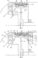
- Fig. 1 shows a part of a well-known housing 2 of a tubular turbine, in which a generator 1 is arranged.
- a rotor 3 is rotatably mounted at one end of a rotatably mounted shaft 7 and thus rotates with the shaft 7 with.
- well-known turbine such as a Kaplan turbine, arranged, which drives the shaft 7 and thus also the generator 1.
- the rotor 3 comprises a hub star 8, which is rotatably connected to the shaft 7 and on which the rotor winding 5 is arranged in a known manner.
- a generator 1 of a tube turbine is typically a slow-speed machine and has a rotor 3 with a salient pole winding, details of which below Fig. 2 ,
- the stator 4 is here in the housing 2 fixed to a support structure 9 spaced from the housing 2 and arranged coaxially around the rotor 3 around and carries stator windings with axially projecting end windings. 6
- Rotor 3 and stator 4 are of conventional design and well-known and arranged, which is why will not be discussed here in detail.
- Such generators 1 must be cooled accordingly due to the electrical losses, for example by air cooling as in Fig. 1 shown.
- cooling air is circulated by means of a fan 10 in the housing 2 in a circle, so that the cooling air over all active generator parts, ie stator 3, rotor 4, windings, is guided and heated there, whereby these parts are cooled simultaneously.
- the heated cooling air is then cooled again in a cooling device 12, such as a heat exchanger.
- the illustrated device according to the invention for cooling the generator 1 consists of a fan 10, which is externally driven, that is not arranged on the shaft 7 and is driven directly from this.
- the fan 10 can be driven, for example via a separate, not specifically shown electric motor.
- the fan 10 now sucks warm cooling air 15 via an intake duct 14 from the generator area, wherein the fan 10 can be, for example, a radial or axial fan.
- the warm cooling air 15 is conveyed by the fan 10 at high pressure to a cooling device 12, cooled and exits the cooling device 12 as cold cooling air 16.
- This cold cooling air 16 is guided via a feed channel 13 to the stator 4, in this example between the housing 2 and stator 4 by means of suitable construction elements 9.
- stator slots 28 see also Fig. 2
- the cold cooling air 16 is now through, here only indicated, stator slots 28 (see also Fig. 2 ) of the stator 4 is thus deflected from a substantially axial in a substantially radially inwardly directed flow.
- the cold cooling air 16 is guided by axial channels in the stator 4 to the stator slots 28, for example, when the stator would be arranged directly on the inner wall of the housing 2.
- heated cooling air 17 is then deflected again in the axial direction and flows on both sides in the axial direction through the air gap 23 to the outside, where this part of the cooling air 17a is further heated.
- a rotor with salient pole winding emerging from the stator cooling air 17 is also pressed radially into the pole gaps 20 of the rotor 3, where this part of the cooling air 17b is deflected again in the axial direction, is further heated and is also guided axially on both sides to the outside.
- the now further heated cooling air 18 flows out.
- a part of this cooling air 19 is also guided over the winding heads 6 of the stator windings 24, for example by corresponding baffles.
- the combined warm cooling air 15 is sucked in again by the fan 10, whereby the cooling air circuit is closed. In this case, the warm cooling air 18 of the second generator half is carried out through corresponding openings 11 in the Nabestern 8.
- the flow through the stator 4 and rotor 3 with a salient pole winding is determined by the Fig. 2 clarified.
- the cold cooling air 16 enters radially into the stator slots 28 of the stator 4.
- the stator slots 28 are formed by spacer webs 26 in the layered stator iron 25.
- the cooling air 16 flows (as indicated by the arrows in FIG Fig. 2 indicated) radially inwardly to the stator winding bars 24, which are arranged in grooves in a conventional manner.
- the now heated cooling air 17 exits radially from the stator 4 and now experiences by the rotating rotor 3 a twist. This heated cooling air 17 is guided on the one hand axially through the air gap 23, as described above.
- the cooling air 17 penetrates into the pole gaps 20, which are formed in a known manner between the arranged in the rotor iron 22 rotor windings 21 of a rotor with salient pole, and is guided by the pole gaps 20 axially outward.
- the rotor 3 could also have slots which allow radial throughflow in addition to the axial flow. This could on the one hand to increase the cooling effect by the rotor 3 additional radially outward (as in Fig. 3 shown), which in turn is guided as an axial flow of cooling air 30 through the pole gaps 20 of the rotor 3 and / or through the air gap 23 axially outward. On the other hand, an inward radial flow would reduce the pressure loss by reducing the axial flow.
- cold cooling air 16 could be diverted directly from the feed channel 13 and this cold cooling air 32 are led directly to the winding heads 6 of the stator winding 24, as in Fig.
Landscapes
- Engineering & Computer Science (AREA)
- Power Engineering (AREA)
- Motor Or Generator Cooling System (AREA)
Abstract
Claims (14)
- Procédé de refroidissement d'un stator (4) et d'un rotor (3) avec bobinage du pôle saillant (5) d'un générateur de turbine bulbe (1), dans lequel un milieu de refroidissement gazeux est circulé dans le générateur de turbine bulbe (1) moyennant au moins un ventilateur à actionnement externe (10), le milieu de refroidissement étant aspiré par le ventilateur (10) à partir du générateur de turbine bulbe (1) et amené au stator (4) entre le stator (4) et le carter (2) de manière que le milieu de refroidissement se trouve refroidi par l'eau motrice froide coulant en dehors du carter (2) du générateur de turbine bulbe (1), caractérisé en ce que le milieu de refroidissement est refoulé moyennant le ventilateur (10) vers un dispositif de refroidissement (12) dans lequel le milieu de refroidissement chaud est refroidi et le milieu de refroidissement refroidi est amené au stator (4) entre le stator (4) et le carter (2) et d'ici mené radialement vers l'intérieur à travers des fentes stator radiales (28) du noyau du stator (25) et est chauffé, et une partie du milieu de refroidissement est menée axialement vers l'extérieur à travers d'un entrefer (23) entre le stator (4) et le rotor (3) et une partie du milieu de refroidissement sortant du stator (4) est pressée dans des espaces interpolaires (20) du rotor (3) et menée axialement vers l'extérieur à travers des espaces interpôlaires (20).
- Procédé selon la revendication 1, caractérisé en ce que le milieu de refroidissement sortant du dispositif de refroidissement (12) est amené au stator (4) vers un canal d'amené (13).
- Procédé selon la revendication 1 ou 2, caractérisé en ce qu'une partie du milieu de refroidissement sortant axialement de l'entrefer (23) et, le cas échéant, des espaces interpolaires (20), est menée au-dessus d'une connexion frontale (6) du stator (4).
- Procédé selon la revendication 1 ou 2, caractérisé en ce que le milieu de refroidissement sortant axialement du dispositif de refroidissement (12) et, le cas échéant, des espaces interpolaires (20), est mené au-dessus d'une connexion frontale (6) du stator (4).
- Procédé selon l'une des revendications 1 à 4, caractérisé en ce qu'une partie du milieu de refroidissement sortant axialement de l'entrefer (23) et, le cas échéant, des espaces interpolaires (20) passe par des ouvertures (11) dans un noyau (8) du rotor (3) d'un côté du rotor (3) à l'autre.
- Procédé selon l'une des revendications 1 à 5, caractérisé en ce qu'une partie du milieu de refroidissement sortant des fentes stator (28) passe par des canaux radiaux du rotor (3).
- Procédé selon l'une des revendications 1 à 6, caractérisé en ce qu'une partie du milieu de refroidissement sortant du dispositif de refroidissement (12) est amené directement aux connexions frontales (6) de l'enroulement stator.
- Procédé selon l'une des revendications 1 à 7, caractérisé en ce que le milieu de refroidissement chaud sortant de l'entrefer (23) et, le cas échéant, des espaces interpolaires (20), est aspiré sur les deux côtés de la machine électrique (1) par au moins un ventilateur à actionnement externe (10).
- Générateur de turbine bulbe (1) comportant- un stator (4),- un rotor (3) avec bobinage du pôle saillant (5) et espaces interpolaires (20),- un carter autour duquel coulent les eaux motrices (2),- au moins un ventilateur à actionnement externe (10) pour circuler un milieu de refroidissement gazeux dans le carter (2),où du milieu chaud sortant axialement d'un entrefer (23) entre le stator (4) et le rotor (3) peut être aspiré moyennant le ventilateur (10) et le stator (4) est disposé à une distance radiale du carter (2) du générateur de turbine bulbe (1), le rotor (3) et le stator (4) étant placés au côté d'aspiration du ventilateur (10), caractérisé en ce qu'un dispositif de refroidissement (12) est prévu pour refroidir un milieu de refroidissement chaud, le milieu de refroidissement sortant du dispositif de refroidissement (12) pouvant passer entre le stator (4) et le carter (2) et le dispositif de refroidissement (12) étant disposé au côté pression du ventilateur (10) et du milieu de refroidissement, qui aurait pénétré dans les espaces interpolaires (20) par des fentes stator radiales (28) pouvant être aspiré à partir des espaces interpolaires.
- Générateur de turbine bulbe selon la revendication 9, caractérisé en ce qu'un canal d'amené (13) est prévu entre le dispositif de refroidissement (12) et le stator (4).
- Générateur de turbine bulbe selon la revendication 9 ou 10, caractérisé en ce qu' un moyen est prévu qui permet de mener un milieu de refroidissement froid sortant du dispositif de refroidissement (12) directement à une connexion frontale (6) de l'enroulement stator.
- Générateur de turbine bulbe selon la revendication 9, 10 ou 11, caractérisé en ce que des canaux radiaux sont prévus dans le rotor (3) dans lesquels peut couler le milieu de refroidissement.
- Générateur de turbine bulbe selon l'une des revendications 9 à 12, caractérisé en ce qu'un enroulement stator (5) est disposé sur un noyau (8) de rotor (3) et que des ouvertures (11) axialement passibles sont disposées sur le noyau (8).
- Générateur de turbine bulbe selon l'une des revendications 9 à 13, caractérisé en ce que sur chaque côté de la machine électrique (1) au moins un ventilateur à actionnement externe (10) est prévu.
Priority Applications (1)
| Application Number | Priority Date | Filing Date | Title |
|---|---|---|---|
| SI200730974T SI2030308T1 (sl) | 2006-06-22 | 2007-06-20 | Postopek hlajenja cevnega turbinskega generatorja in cevni turbinski generator |
Applications Claiming Priority (2)
| Application Number | Priority Date | Filing Date | Title |
|---|---|---|---|
| AT0106106A AT504057A1 (de) | 2006-06-22 | 2006-06-22 | Verfahren und vorrichtung zur kühlung einer elektrischen maschine |
| PCT/AT2007/000300 WO2007147187A1 (fr) | 2006-06-22 | 2007-06-20 | Procédé et dispositif de refroidissement d'un moteur électrique |
Publications (2)
| Publication Number | Publication Date |
|---|---|
| EP2030308A1 EP2030308A1 (fr) | 2009-03-04 |
| EP2030308B1 true EP2030308B1 (fr) | 2012-05-02 |
Family
ID=38543637
Family Applications (1)
| Application Number | Title | Priority Date | Filing Date |
|---|---|---|---|
| EP07718509A Not-in-force EP2030308B1 (fr) | 2006-06-22 | 2007-06-20 | Procédé de refroidissement d'une turbine générateur bulbe hydraulique et turbine générateur bulbe hydraulique |
Country Status (11)
| Country | Link |
|---|---|
| US (2) | US8035261B2 (fr) |
| EP (1) | EP2030308B1 (fr) |
| JP (1) | JP2009542168A (fr) |
| CN (1) | CN101473514B (fr) |
| AT (2) | AT504057A1 (fr) |
| BR (1) | BRPI0713603A2 (fr) |
| CA (1) | CA2656986C (fr) |
| ES (1) | ES2390481T3 (fr) |
| PT (1) | PT2030308E (fr) |
| SI (1) | SI2030308T1 (fr) |
| WO (1) | WO2007147187A1 (fr) |
Cited By (1)
| Publication number | Priority date | Publication date | Assignee | Title |
|---|---|---|---|---|
| DE102018208706A1 (de) | 2018-06-04 | 2019-12-05 | Audi Ag | System zum Kühlen einer Elektromaschine |
Families Citing this family (20)
| Publication number | Priority date | Publication date | Assignee | Title |
|---|---|---|---|---|
| DE102008017537A1 (de) | 2008-04-03 | 2009-10-08 | Voith Patent Gmbh | Rohrturbinen-Generatoreinheit |
| CN102157997B (zh) * | 2011-01-26 | 2013-01-23 | 高超 | 带有冷却风罩的永磁调速机 |
| US9168585B2 (en) * | 2012-11-02 | 2015-10-27 | Mueller International, Llc | Coupling with extending parting line |
| US9461523B2 (en) * | 2013-12-12 | 2016-10-04 | Baldor Electric Company | Two phase gap cooling of an electrical machine |
| DE102014009146A1 (de) * | 2014-06-20 | 2015-12-24 | Ziehl-Abegg Se | Elektromotor mit einem Rotor, einem Stator und einem Elektronikgehäuse sowie Lüfterrad für einen Elektromotor |
| EP3079229A1 (fr) | 2015-04-09 | 2016-10-12 | Siemens Aktiengesellschaft | Refroidissement d'une machine électrique |
| US10715013B2 (en) | 2016-01-14 | 2020-07-14 | Honeywell International Inc. | Compact high speed generator having respective oil and air cooling passages |
| US10411562B2 (en) | 2016-01-14 | 2019-09-10 | Honeywell International Inc. | Compact high speed generator having passageways for air and cooling oil |
| CN107134885A (zh) * | 2016-02-29 | 2017-09-05 | 珠海格力电器股份有限公司 | 永磁同步电机组件及具有其的压缩机和空调器 |
| CN107261357A (zh) * | 2017-07-19 | 2017-10-20 | 宁波市北仑区柴桥申亚电子灯饰厂 | 移动式超速安全防护系统 |
| CN107834774A (zh) * | 2017-12-18 | 2018-03-23 | 东方电气集团东方电机有限公司 | 一种定子带通风槽口的电机 |
| CN109412339B (zh) | 2018-09-06 | 2020-04-28 | 新疆金风科技股份有限公司 | 电机及风力发电机组 |
| KR102090569B1 (ko) * | 2019-05-09 | 2020-03-18 | (주) 디엔디이 | 벌브 수차발전기의 냉각구조 및 냉각방법 |
| CN110417188B (zh) * | 2019-07-08 | 2020-06-12 | 浙江大学 | 电机的冷却装置 |
| CN110518728B (zh) * | 2019-08-29 | 2020-09-08 | 东方电气集团东方电机有限公司 | 一种带有转子风路的风力发电机 |
| CN110504771B (zh) * | 2019-08-30 | 2021-04-02 | 东方电气集团东方电机有限公司 | 一种用于改善定子轴向温度分布均匀性的装置 |
| CN112421885A (zh) * | 2020-11-10 | 2021-02-26 | 国家电网有限公司 | 水轮发电机闭路自循环通风冷却系统 |
| CN112994354B (zh) * | 2021-02-20 | 2022-02-18 | 浙江富春江水电设备有限公司 | 一种无空冷器的大型灯泡贯流式水轮发电机通风冷却系统 |
| EP4102682A1 (fr) * | 2021-06-09 | 2022-12-14 | Siemens Gamesa Renewable Energy A/S | Générateur, éolienne et procédé de refroidissement d'un générateur à entraînement direct d'une éolienne |
| ES3074022T3 (en) * | 2021-07-27 | 2026-07-16 | Ge Vernova Renovables Espana S L | Cooling of active elements of electrical machines |
Family Cites Families (26)
| Publication number | Priority date | Publication date | Assignee | Title |
|---|---|---|---|---|
| FR1022783A (fr) | 1950-08-03 | 1953-03-10 | Alsthom Cgee | Perfectionnements apportés au refroidissement des machines électriques fermées |
| US2873393A (en) * | 1957-03-28 | 1959-02-10 | Westinghouse Electric Corp | Dual-ventilation hydrogen-cooled generators |
| JPS5546849A (en) | 1978-09-26 | 1980-04-02 | Mitsubishi Electric Corp | Rotary electric machine |
| SU855871A1 (ru) | 1979-11-01 | 1981-08-15 | За витель А. Макс -гмов 61) Дополнительное к авт. сзкд-ву | Синхронна электрическа машина с вновыраженными полюсами |
| JPS58107042A (ja) | 1981-12-17 | 1983-06-25 | Toshiba Corp | 回転電機 |
| JPS58123348A (ja) | 1982-01-19 | 1983-07-22 | Toshiba Corp | 突極形回転電機 |
| JPS59220045A (ja) * | 1983-05-25 | 1984-12-11 | Fuji Electric Co Ltd | バルブ水車発電機 |
| JPH04133641A (ja) | 1990-09-20 | 1992-05-07 | Toshiba Corp | 突極形回転電機 |
| JPH04340347A (ja) | 1991-05-14 | 1992-11-26 | Toshiba Corp | 突極形回転電機 |
| DE59104517D1 (de) * | 1991-11-25 | 1995-03-16 | Asea Brown Boveri | Gasgekühlte elektrische Maschine. |
| JPH06237554A (ja) | 1993-02-10 | 1994-08-23 | Fuji Electric Co Ltd | バルブ水車発電機 |
| JPH06284639A (ja) | 1993-03-30 | 1994-10-07 | Toshiba Corp | 回転電機の冷却装置 |
| JPH0787709A (ja) | 1993-09-13 | 1995-03-31 | Toshiba Corp | 突極形回転電機 |
| JPH07245914A (ja) * | 1994-01-11 | 1995-09-19 | Fuji Electric Co Ltd | 回転電機の冷却風通風装置 |
| US5652469A (en) | 1994-06-16 | 1997-07-29 | General Electric Company | Reverse flow ventilation system with stator core center discharge duct and/or end region cooling system |
| US5633543A (en) * | 1994-12-12 | 1997-05-27 | General Electric Co. | Pressure equalizer and method for reverse flow ventilated armature in power generator |
| JPH10322975A (ja) * | 1997-05-16 | 1998-12-04 | Hitachi Ltd | 回転電機の通風構造 |
| JP3289698B2 (ja) * | 1998-11-25 | 2002-06-10 | 株式会社日立製作所 | 回転電機 |
| DE19856456A1 (de) | 1998-12-03 | 2000-06-08 | Asea Brown Boveri | Gasgekühlte elektrische Maschine mit einem Axialventilator |
| US6737768B2 (en) * | 2000-03-31 | 2004-05-18 | Hitachi, Ltd. | Rotating electric machine |
| US6346753B1 (en) | 2000-04-18 | 2002-02-12 | General Electric Company | Fan and rotor dynamic gas sealing system |
| EP1182764A1 (fr) * | 2000-08-23 | 2002-02-27 | ABB Industrie AG | Refroidissement des machines électriques à grande vitesse |
| CA2324696C (fr) * | 2000-10-26 | 2008-06-10 | General Electric Canada Inc. | Machine dynaelectrique a roteur de distribution pour ventilation |
| US6703729B2 (en) * | 2001-08-15 | 2004-03-09 | General Electric Company | Reverse flow stator ventilation system for superconducting synchronous machine |
| US6882068B2 (en) | 2002-10-08 | 2005-04-19 | General Electric Company | Forced air stator ventilation system and stator ventilation method for superconducting synchronous machine |
| US7843099B2 (en) * | 2005-04-25 | 2010-11-30 | William Sheridan Fielder | Hollow generator |
-
2006
- 2006-06-22 AT AT0106106A patent/AT504057A1/de not_active Application Discontinuation
-
2007
- 2007-06-20 ES ES07718509T patent/ES2390481T3/es active Active
- 2007-06-20 CA CA2656986A patent/CA2656986C/fr not_active Expired - Fee Related
- 2007-06-20 JP JP2009515670A patent/JP2009542168A/ja active Pending
- 2007-06-20 SI SI200730974T patent/SI2030308T1/sl unknown
- 2007-06-20 EP EP07718509A patent/EP2030308B1/fr not_active Not-in-force
- 2007-06-20 AT AT07718509T patent/ATE556478T1/de active
- 2007-06-20 PT PT07718509T patent/PT2030308E/pt unknown
- 2007-06-20 BR BRPI0713603-0A patent/BRPI0713603A2/pt not_active Application Discontinuation
- 2007-06-20 WO PCT/AT2007/000300 patent/WO2007147187A1/fr not_active Ceased
- 2007-06-20 US US12/306,112 patent/US8035261B2/en not_active Expired - Fee Related
- 2007-06-20 CN CN200780023163XA patent/CN101473514B/zh not_active Expired - Fee Related
-
2011
- 2011-09-15 US US13/233,115 patent/US8288901B2/en not_active Expired - Fee Related
Cited By (2)
| Publication number | Priority date | Publication date | Assignee | Title |
|---|---|---|---|---|
| DE102018208706A1 (de) | 2018-06-04 | 2019-12-05 | Audi Ag | System zum Kühlen einer Elektromaschine |
| US10992195B2 (en) | 2018-06-04 | 2021-04-27 | Audi Ag | System for cooling an electric machine |
Also Published As
| Publication number | Publication date |
|---|---|
| US20120025641A1 (en) | 2012-02-02 |
| EP2030308A1 (fr) | 2009-03-04 |
| BRPI0713603A2 (pt) | 2012-11-06 |
| CA2656986A1 (fr) | 2007-12-27 |
| ATE556478T1 (de) | 2012-05-15 |
| US20100026110A1 (en) | 2010-02-04 |
| US8035261B2 (en) | 2011-10-11 |
| SI2030308T1 (sl) | 2012-09-28 |
| PT2030308E (pt) | 2012-08-06 |
| CN101473514A (zh) | 2009-07-01 |
| AT504057A1 (de) | 2008-02-15 |
| JP2009542168A (ja) | 2009-11-26 |
| CA2656986C (fr) | 2014-09-16 |
| US8288901B2 (en) | 2012-10-16 |
| CN101473514B (zh) | 2012-06-06 |
| WO2007147187A1 (fr) | 2007-12-27 |
| ES2390481T3 (es) | 2012-11-13 |
Similar Documents
| Publication | Publication Date | Title |
|---|---|---|
| EP2030308A1 (fr) | Procédé et dispositif de refroidissement d'un moteur électrique | |
| DE102008022105B4 (de) | Flüssigkeitsgekühlte elektrische Maschine sowie Verfahren zur Kühlung einer solchen elektrischen Maschine | |
| EP2223414B1 (fr) | Machine électrique à double ventilateur axial | |
| DE102009051651B4 (de) | Windkraftgenerator mit Innenkühlkreislauf | |
| EP2062343B1 (fr) | Machine electrique avec rotor a refroidissement | |
| DE10355385A1 (de) | Dichtungseinrichtung für das Belüftungssystem eines elektrischen Generators | |
| EP1006644B1 (fr) | Machine électrique refroidie par gaz avec ventilateur axial | |
| DE102010029986A1 (de) | Dynamoelektrische Maschine mit Luft-Flüssigkeitskühlung | |
| DE10307813B4 (de) | Elektrische Maschine | |
| CH323433A (de) | Verfahren und Einrichtung zum Kühlen von elektrischen Leitern einer ganz gekapselten, dynamoelektrischen Maschine | |
| DE3015435C2 (de) | Schenkelpol-Synchronmaschine | |
| DE2608291A1 (de) | Gasgekuehlter generator-rotor mit erhoehter ventilation | |
| DE102014115666B4 (de) | Offener Induktionsmotor | |
| DE1014216B (de) | Gasgekuehlte Dynamomaschine | |
| DE60128583T2 (de) | Belüftung eines rotors einer dynamoelektrischen maschine | |
| EP3326264A1 (fr) | Anneau statorique, générateur et éolienne équipée | |
| DE2626517A1 (de) | Ventilationssystem fuer dynamoelektrische maschinen | |
| DE19919040C2 (de) | Synchronmaschine oder Asychronmaschine für große Windenergieanlagen | |
| DE2007194A1 (de) | Kühlgasführung bei elektrischen Maschinen | |
| CH665066A5 (de) | Geblaesediffusor- und kollektoranordnung als teil eines kuehlsystems in einer dynamoelektrischen maschine. | |
| EP3804095B1 (fr) | Rotor pour une machine électrique, en particulier d'un véhicule automobile, ainsi que machine électrique, en particulier pour un véhicule automobile | |
| DE29913314U1 (de) | Elektrische Maschine | |
| DE102013100453A1 (de) | Innenkühlkreislaufsystem für rotierende elektrische Maschinen | |
| DE10054338C2 (de) | Kühlsystem für trägheitsarme rotierende elektrische Maschine | |
| DE10225221B4 (de) | Belüftung eines Ringmotors für eine Rohrmühle |
Legal Events
| Date | Code | Title | Description |
|---|---|---|---|
| PUAI | Public reference made under article 153(3) epc to a published international application that has entered the european phase |
Free format text: ORIGINAL CODE: 0009012 |
|
| 17P | Request for examination filed |
Effective date: 20081203 |
|
| AK | Designated contracting states |
Kind code of ref document: A1 Designated state(s): AT BE BG CH CY CZ DE DK EE ES FI FR GB GR HU IE IS IT LI LT LU LV MC MT NL PL PT RO SE SI SK TR |
|
| AX | Request for extension of the european patent |
Extension state: AL BA HR MK RS |
|
| 17Q | First examination report despatched |
Effective date: 20091001 |
|
| RAP1 | Party data changed (applicant data changed or rights of an application transferred) |
Owner name: ANDRITZ HYDRO GMBH |
|
| RTI1 | Title (correction) |
Free format text: METHOD FOR COOLING A SUBMERGED HYDRAULIC TURBINE-GENERATOR AND SUBMERGED HYDRAULIC TURBINE-GENERATOR |
|
| GRAP | Despatch of communication of intention to grant a patent |
Free format text: ORIGINAL CODE: EPIDOSNIGR1 |
|
| DAX | Request for extension of the european patent (deleted) | ||
| GRAS | Grant fee paid |
Free format text: ORIGINAL CODE: EPIDOSNIGR3 |
|
| GRAA | (expected) grant |
Free format text: ORIGINAL CODE: 0009210 |
|
| AK | Designated contracting states |
Kind code of ref document: B1 Designated state(s): AT BE BG CH CY CZ DE DK EE ES FI FR GB GR HU IE IS IT LI LT LU LV MC MT NL PL PT RO SE SI SK TR |
|
| REG | Reference to a national code |
Ref country code: GB Ref legal event code: FG4D Free format text: NOT ENGLISH |
|
| REG | Reference to a national code |
Ref country code: AT Ref legal event code: REF Ref document number: 556478 Country of ref document: AT Kind code of ref document: T Effective date: 20120515 Ref country code: CH Ref legal event code: EP |
|
| REG | Reference to a national code |
Ref country code: IE Ref legal event code: FG4D Free format text: LANGUAGE OF EP DOCUMENT: GERMAN |
|
| REG | Reference to a national code |
Ref country code: DE Ref legal event code: R096 Ref document number: 502007009819 Country of ref document: DE Effective date: 20120628 |
|
| REG | Reference to a national code |
Ref country code: CH Ref legal event code: NV Representative=s name: FIAMMENGHI-FIAMMENGHI Ref country code: RO Ref legal event code: EPE |
|
| REG | Reference to a national code |
Ref country code: PT Ref legal event code: SC4A Free format text: AVAILABILITY OF NATIONAL TRANSLATION Effective date: 20120731 |
|
| REG | Reference to a national code |
Ref country code: SE Ref legal event code: TRGR |
|
| REG | Reference to a national code |
Ref country code: NL Ref legal event code: VDEP Effective date: 20120502 |
|
| PG25 | Lapsed in a contracting state [announced via postgrant information from national office to epo] |
Ref country code: CY Free format text: LAPSE BECAUSE OF FAILURE TO SUBMIT A TRANSLATION OF THE DESCRIPTION OR TO PAY THE FEE WITHIN THE PRESCRIBED TIME-LIMIT Effective date: 20120502 Ref country code: IS Free format text: LAPSE BECAUSE OF FAILURE TO SUBMIT A TRANSLATION OF THE DESCRIPTION OR TO PAY THE FEE WITHIN THE PRESCRIBED TIME-LIMIT Effective date: 20120902 Ref country code: PL Free format text: LAPSE BECAUSE OF FAILURE TO SUBMIT A TRANSLATION OF THE DESCRIPTION OR TO PAY THE FEE WITHIN THE PRESCRIBED TIME-LIMIT Effective date: 20120502 |
|
| REG | Reference to a national code |
Ref country code: ES Ref legal event code: FG2A Ref document number: 2390481 Country of ref document: ES Kind code of ref document: T3 Effective date: 20121113 |
|
| PG25 | Lapsed in a contracting state [announced via postgrant information from national office to epo] |
Ref country code: GR Free format text: LAPSE BECAUSE OF FAILURE TO SUBMIT A TRANSLATION OF THE DESCRIPTION OR TO PAY THE FEE WITHIN THE PRESCRIBED TIME-LIMIT Effective date: 20120803 |
|
| BERE | Be: lapsed |
Owner name: ANDRITZ HYDRO GMBH Effective date: 20120630 |
|
| PG25 | Lapsed in a contracting state [announced via postgrant information from national office to epo] |
Ref country code: CZ Free format text: LAPSE BECAUSE OF FAILURE TO SUBMIT A TRANSLATION OF THE DESCRIPTION OR TO PAY THE FEE WITHIN THE PRESCRIBED TIME-LIMIT Effective date: 20120502 Ref country code: NL Free format text: LAPSE BECAUSE OF FAILURE TO SUBMIT A TRANSLATION OF THE DESCRIPTION OR TO PAY THE FEE WITHIN THE PRESCRIBED TIME-LIMIT Effective date: 20120502 Ref country code: SK Free format text: LAPSE BECAUSE OF FAILURE TO SUBMIT A TRANSLATION OF THE DESCRIPTION OR TO PAY THE FEE WITHIN THE PRESCRIBED TIME-LIMIT Effective date: 20120502 Ref country code: DK Free format text: LAPSE BECAUSE OF FAILURE TO SUBMIT A TRANSLATION OF THE DESCRIPTION OR TO PAY THE FEE WITHIN THE PRESCRIBED TIME-LIMIT Effective date: 20120502 Ref country code: MC Free format text: LAPSE BECAUSE OF NON-PAYMENT OF DUE FEES Effective date: 20120630 Ref country code: EE Free format text: LAPSE BECAUSE OF FAILURE TO SUBMIT A TRANSLATION OF THE DESCRIPTION OR TO PAY THE FEE WITHIN THE PRESCRIBED TIME-LIMIT Effective date: 20120502 |
|
| PG25 | Lapsed in a contracting state [announced via postgrant information from national office to epo] |
Ref country code: IT Free format text: LAPSE BECAUSE OF FAILURE TO SUBMIT A TRANSLATION OF THE DESCRIPTION OR TO PAY THE FEE WITHIN THE PRESCRIBED TIME-LIMIT Effective date: 20120502 |
|
| PLBE | No opposition filed within time limit |
Free format text: ORIGINAL CODE: 0009261 |
|
| STAA | Information on the status of an ep patent application or granted ep patent |
Free format text: STATUS: NO OPPOSITION FILED WITHIN TIME LIMIT |
|
| REG | Reference to a national code |
Ref country code: IE Ref legal event code: MM4A |
|
| 26N | No opposition filed |
Effective date: 20130205 |
|
| GBPC | Gb: european patent ceased through non-payment of renewal fee |
Effective date: 20120802 |
|
| PG25 | Lapsed in a contracting state [announced via postgrant information from national office to epo] |
Ref country code: BE Free format text: LAPSE BECAUSE OF NON-PAYMENT OF DUE FEES Effective date: 20120630 Ref country code: IE Free format text: LAPSE BECAUSE OF NON-PAYMENT OF DUE FEES Effective date: 20120620 |
|
| REG | Reference to a national code |
Ref country code: DE Ref legal event code: R097 Ref document number: 502007009819 Country of ref document: DE Effective date: 20130205 |
|
| PG25 | Lapsed in a contracting state [announced via postgrant information from national office to epo] |
Ref country code: BG Free format text: LAPSE BECAUSE OF FAILURE TO SUBMIT A TRANSLATION OF THE DESCRIPTION OR TO PAY THE FEE WITHIN THE PRESCRIBED TIME-LIMIT Effective date: 20120802 Ref country code: MT Free format text: LAPSE BECAUSE OF FAILURE TO SUBMIT A TRANSLATION OF THE DESCRIPTION OR TO PAY THE FEE WITHIN THE PRESCRIBED TIME-LIMIT Effective date: 20120502 Ref country code: GB Free format text: LAPSE BECAUSE OF NON-PAYMENT OF DUE FEES Effective date: 20120802 |
|
| PG25 | Lapsed in a contracting state [announced via postgrant information from national office to epo] |
Ref country code: TR Free format text: LAPSE BECAUSE OF FAILURE TO SUBMIT A TRANSLATION OF THE DESCRIPTION OR TO PAY THE FEE WITHIN THE PRESCRIBED TIME-LIMIT Effective date: 20120502 |
|
| PG25 | Lapsed in a contracting state [announced via postgrant information from national office to epo] |
Ref country code: LU Free format text: LAPSE BECAUSE OF NON-PAYMENT OF DUE FEES Effective date: 20120620 |
|
| PG25 | Lapsed in a contracting state [announced via postgrant information from national office to epo] |
Ref country code: HU Free format text: LAPSE BECAUSE OF FAILURE TO SUBMIT A TRANSLATION OF THE DESCRIPTION OR TO PAY THE FEE WITHIN THE PRESCRIBED TIME-LIMIT Effective date: 20070620 |
|
| REG | Reference to a national code |
Ref country code: FR Ref legal event code: PLFP Year of fee payment: 10 |
|
| REG | Reference to a national code |
Ref country code: FR Ref legal event code: PLFP Year of fee payment: 11 |
|
| PGFP | Annual fee paid to national office [announced via postgrant information from national office to epo] |
Ref country code: LT Payment date: 20170613 Year of fee payment: 11 Ref country code: RO Payment date: 20170615 Year of fee payment: 11 Ref country code: FR Payment date: 20170621 Year of fee payment: 11 |
|
| REG | Reference to a national code |
Ref country code: CH Ref legal event code: NV Representative=s name: KELLER AND PARTNER PATENTANWAELTE AG, CH Ref country code: CH Ref legal event code: PUE Owner name: JOHANNES ERHARD, AT Free format text: FORMER OWNER: ANDRITZ HYDRO GMBH, AT |
|
| PGFP | Annual fee paid to national office [announced via postgrant information from national office to epo] |
Ref country code: SE Payment date: 20170620 Year of fee payment: 11 Ref country code: SI Payment date: 20170619 Year of fee payment: 11 Ref country code: PT Payment date: 20170616 Year of fee payment: 11 Ref country code: LV Payment date: 20170619 Year of fee payment: 11 Ref country code: FI Payment date: 20170621 Year of fee payment: 11 |
|
| REG | Reference to a national code |
Ref country code: SI Ref legal event code: SP73 Owner name: JOHANNES ERHARD; AT Effective date: 20170824 |
|
| REG | Reference to a national code |
Ref country code: DE Ref legal event code: R082 Ref document number: 502007009819 Country of ref document: DE Representative=s name: ZEUNER SUMMERER STUETZ PATENT- UND RECHTSANWAL, DE Ref country code: DE Ref legal event code: R081 Ref document number: 502007009819 Country of ref document: DE Owner name: ERHARD, JOHANNES, AT Free format text: FORMER OWNER: ANDRITZ HYDRO GMBH, WIEN, AT |
|
| PGFP | Annual fee paid to national office [announced via postgrant information from national office to epo] |
Ref country code: ES Payment date: 20170725 Year of fee payment: 11 |
|
| REG | Reference to a national code |
Ref country code: ES Ref legal event code: PC2A Owner name: ERHARD, JOHANNES Effective date: 20171026 |
|
| REG | Reference to a national code |
Ref country code: AT Ref legal event code: PC Ref document number: 556478 Country of ref document: AT Kind code of ref document: T Owner name: JOHANNES ERHARD, AT Effective date: 20170926 |
|
| REG | Reference to a national code |
Ref country code: FR Ref legal event code: TP Owner name: JOHANNES ERHARD, AT Effective date: 20171220 |
|
| PGFP | Annual fee paid to national office [announced via postgrant information from national office to epo] |
Ref country code: CH Payment date: 20180621 Year of fee payment: 12 Ref country code: DE Payment date: 20180625 Year of fee payment: 12 |
|
| PGFP | Annual fee paid to national office [announced via postgrant information from national office to epo] |
Ref country code: AT Payment date: 20180611 Year of fee payment: 12 |
|
| REG | Reference to a national code |
Ref country code: LT Ref legal event code: MM4D Effective date: 20180620 |
|
| REG | Reference to a national code |
Ref country code: SE Ref legal event code: EUG |
|
| PG25 | Lapsed in a contracting state [announced via postgrant information from national office to epo] |
Ref country code: SE Free format text: LAPSE BECAUSE OF NON-PAYMENT OF DUE FEES Effective date: 20180621 Ref country code: FI Free format text: LAPSE BECAUSE OF NON-PAYMENT OF DUE FEES Effective date: 20180620 Ref country code: LT Free format text: LAPSE BECAUSE OF NON-PAYMENT OF DUE FEES Effective date: 20180620 Ref country code: RO Free format text: LAPSE BECAUSE OF NON-PAYMENT OF DUE FEES Effective date: 20180620 |
|
| PG25 | Lapsed in a contracting state [announced via postgrant information from national office to epo] |
Ref country code: LV Free format text: LAPSE BECAUSE OF NON-PAYMENT OF DUE FEES Effective date: 20180620 |
|
| REG | Reference to a national code |
Ref country code: SI Ref legal event code: KO00 Effective date: 20190215 |
|
| PG25 | Lapsed in a contracting state [announced via postgrant information from national office to epo] |
Ref country code: FR Free format text: LAPSE BECAUSE OF NON-PAYMENT OF DUE FEES Effective date: 20180630 |
|
| PG25 | Lapsed in a contracting state [announced via postgrant information from national office to epo] |
Ref country code: SI Free format text: LAPSE BECAUSE OF NON-PAYMENT OF DUE FEES Effective date: 20180621 |
|
| REG | Reference to a national code |
Ref country code: ES Ref legal event code: FD2A Effective date: 20190916 |
|
| PG25 | Lapsed in a contracting state [announced via postgrant information from national office to epo] |
Ref country code: ES Free format text: LAPSE BECAUSE OF NON-PAYMENT OF DUE FEES Effective date: 20180621 |
|
| REG | Reference to a national code |
Ref country code: DE Ref legal event code: R119 Ref document number: 502007009819 Country of ref document: DE |
|
| REG | Reference to a national code |
Ref country code: CH Ref legal event code: PL |
|
| REG | Reference to a national code |
Ref country code: AT Ref legal event code: MM01 Ref document number: 556478 Country of ref document: AT Kind code of ref document: T Effective date: 20190620 |
|
| PG25 | Lapsed in a contracting state [announced via postgrant information from national office to epo] |
Ref country code: AT Free format text: LAPSE BECAUSE OF NON-PAYMENT OF DUE FEES Effective date: 20190620 Ref country code: DE Free format text: LAPSE BECAUSE OF NON-PAYMENT OF DUE FEES Effective date: 20200101 |
|
| PG25 | Lapsed in a contracting state [announced via postgrant information from national office to epo] |
Ref country code: LI Free format text: LAPSE BECAUSE OF NON-PAYMENT OF DUE FEES Effective date: 20190630 Ref country code: CH Free format text: LAPSE BECAUSE OF NON-PAYMENT OF DUE FEES Effective date: 20190630 |
|
| PG25 | Lapsed in a contracting state [announced via postgrant information from national office to epo] |
Ref country code: PT Free format text: LAPSE BECAUSE OF NON-PAYMENT OF DUE FEES Effective date: 20181220 |