EP2053214A1 - 6-takt-motor mit regenerator - Google Patents
6-takt-motor mit regenerator Download PDFInfo
- Publication number
- EP2053214A1 EP2053214A1 EP07792007A EP07792007A EP2053214A1 EP 2053214 A1 EP2053214 A1 EP 2053214A1 EP 07792007 A EP07792007 A EP 07792007A EP 07792007 A EP07792007 A EP 07792007A EP 2053214 A1 EP2053214 A1 EP 2053214A1
- Authority
- EP
- European Patent Office
- Prior art keywords
- engine
- regenerator
- cycle engine
- cycle
- exhaust
- Prior art date
- Legal status (The legal status is an assumption and is not a legal conclusion. Google has not performed a legal analysis and makes no representation as to the accuracy of the status listed.)
- Withdrawn
Links
- 238000002485 combustion reaction Methods 0.000 claims abstract description 134
- 230000001172 regenerating effect Effects 0.000 claims abstract description 83
- 238000006073 displacement reaction Methods 0.000 claims abstract description 31
- 230000002000 scavenging effect Effects 0.000 claims description 86
- 230000005540 biological transmission Effects 0.000 claims description 17
- 230000007246 mechanism Effects 0.000 claims description 11
- 239000000284 extract Substances 0.000 claims description 4
- 239000012774 insulation material Substances 0.000 claims 1
- 239000000446 fuel Substances 0.000 abstract description 79
- 230000002159 abnormal effect Effects 0.000 abstract description 11
- 238000002844 melting Methods 0.000 abstract description 6
- 230000008018 melting Effects 0.000 abstract description 6
- 230000006378 damage Effects 0.000 abstract description 3
- 239000007789 gas Substances 0.000 description 190
- 238000007906 compression Methods 0.000 description 24
- 230000006835 compression Effects 0.000 description 23
- 238000010586 diagram Methods 0.000 description 23
- 230000000694 effects Effects 0.000 description 21
- 239000003054 catalyst Substances 0.000 description 16
- 238000001816 cooling Methods 0.000 description 14
- QVGXLLKOCUKJST-UHFFFAOYSA-N atomic oxygen Chemical compound [O] QVGXLLKOCUKJST-UHFFFAOYSA-N 0.000 description 13
- 238000004880 explosion Methods 0.000 description 13
- 238000000034 method Methods 0.000 description 13
- 239000001301 oxygen Substances 0.000 description 13
- 229910052760 oxygen Inorganic materials 0.000 description 13
- 230000001965 increasing effect Effects 0.000 description 12
- 230000008901 benefit Effects 0.000 description 11
- 230000003247 decreasing effect Effects 0.000 description 7
- 238000002347 injection Methods 0.000 description 7
- 239000007924 injection Substances 0.000 description 7
- 239000000203 mixture Substances 0.000 description 7
- MWUXSHHQAYIFBG-UHFFFAOYSA-N nitrogen oxide Inorganic materials O=[N] MWUXSHHQAYIFBG-UHFFFAOYSA-N 0.000 description 6
- 230000008569 process Effects 0.000 description 6
- 230000007423 decrease Effects 0.000 description 5
- 230000009467 reduction Effects 0.000 description 5
- 230000005611 electricity Effects 0.000 description 4
- 239000003517 fume Substances 0.000 description 4
- 239000000498 cooling water Substances 0.000 description 3
- 239000011810 insulating material Substances 0.000 description 3
- 230000033001 locomotion Effects 0.000 description 3
- 239000000463 material Substances 0.000 description 3
- 230000002093 peripheral effect Effects 0.000 description 3
- 238000010248 power generation Methods 0.000 description 3
- 230000002829 reductive effect Effects 0.000 description 3
- 230000000087 stabilizing effect Effects 0.000 description 3
- 239000002699 waste material Substances 0.000 description 3
- 230000003197 catalytic effect Effects 0.000 description 2
- 230000008859 change Effects 0.000 description 2
- 125000004122 cyclic group Chemical group 0.000 description 2
- 230000002708 enhancing effect Effects 0.000 description 2
- 239000004615 ingredient Substances 0.000 description 2
- 230000001737 promoting effect Effects 0.000 description 2
- 230000008929 regeneration Effects 0.000 description 2
- 238000011069 regeneration method Methods 0.000 description 2
- 230000003685 thermal hair damage Effects 0.000 description 2
- 241001085768 Stereolepis gigas Species 0.000 description 1
- 230000001133 acceleration Effects 0.000 description 1
- 239000003990 capacitor Substances 0.000 description 1
- 239000000919 ceramic Substances 0.000 description 1
- 239000011248 coating agent Substances 0.000 description 1
- 238000000576 coating method Methods 0.000 description 1
- 230000007547 defect Effects 0.000 description 1
- 230000018109 developmental process Effects 0.000 description 1
- 238000007599 discharging Methods 0.000 description 1
- 238000010892 electric spark Methods 0.000 description 1
- 239000012530 fluid Substances 0.000 description 1
- 230000004907 flux Effects 0.000 description 1
- 239000002737 fuel gas Substances 0.000 description 1
- 239000003502 gasoline Substances 0.000 description 1
- 230000000977 initiatory effect Effects 0.000 description 1
- 238000009434 installation Methods 0.000 description 1
- 238000009413 insulation Methods 0.000 description 1
- 238000005086 pumping Methods 0.000 description 1
- 230000004044 response Effects 0.000 description 1
- 238000005728 strengthening Methods 0.000 description 1
- 230000029305 taxis Effects 0.000 description 1
- 238000005406 washing Methods 0.000 description 1
Images


Classifications
-
- F—MECHANICAL ENGINEERING; LIGHTING; HEATING; WEAPONS; BLASTING
- F02—COMBUSTION ENGINES; HOT-GAS OR COMBUSTION-PRODUCT ENGINE PLANTS
- F02B—INTERNAL-COMBUSTION PISTON ENGINES; COMBUSTION ENGINES IN GENERAL
- F02B41/00—Engines characterised by special means for improving conversion of heat or pressure energy into mechanical power
- F02B41/02—Engines with prolonged expansion
- F02B41/10—Engines with prolonged expansion in exhaust turbines
-
- F—MECHANICAL ENGINEERING; LIGHTING; HEATING; WEAPONS; BLASTING
- F02—COMBUSTION ENGINES; HOT-GAS OR COMBUSTION-PRODUCT ENGINE PLANTS
- F02B—INTERNAL-COMBUSTION PISTON ENGINES; COMBUSTION ENGINES IN GENERAL
- F02B75/00—Other engines
- F02B75/02—Engines characterised by their cycles, e.g. six-stroke
- F02B75/021—Engines characterised by their cycles, e.g. six-stroke having six or more strokes per cycle
-
- F—MECHANICAL ENGINEERING; LIGHTING; HEATING; WEAPONS; BLASTING
- F01—MACHINES OR ENGINES IN GENERAL; ENGINE PLANTS IN GENERAL; STEAM ENGINES
- F01L—CYCLICALLY OPERATING VALVES FOR MACHINES OR ENGINES
- F01L1/00—Valve-gear or valve arrangements, e.g. lift-valve gear
- F01L1/36—Valve-gear or valve arrangements, e.g. lift-valve gear peculiar to machines or engines of specific type other than four-stroke cycle
- F01L1/38—Valve-gear or valve arrangements, e.g. lift-valve gear peculiar to machines or engines of specific type other than four-stroke cycle for engines with other than four-stroke cycle, e.g. with two-stroke cycle
-
- F—MECHANICAL ENGINEERING; LIGHTING; HEATING; WEAPONS; BLASTING
- F02—COMBUSTION ENGINES; HOT-GAS OR COMBUSTION-PRODUCT ENGINE PLANTS
- F02B—INTERNAL-COMBUSTION PISTON ENGINES; COMBUSTION ENGINES IN GENERAL
- F02B25/00—Engines characterised by using fresh charge for scavenging cylinders
- F02B25/26—Multi-cylinder engines other than those provided for in, or of interest apart from, groups F02B25/02 - F02B25/24
-
- F—MECHANICAL ENGINEERING; LIGHTING; HEATING; WEAPONS; BLASTING
- F02—COMBUSTION ENGINES; HOT-GAS OR COMBUSTION-PRODUCT ENGINE PLANTS
- F02B—INTERNAL-COMBUSTION PISTON ENGINES; COMBUSTION ENGINES IN GENERAL
- F02B31/00—Modifying induction systems for imparting a rotation to the charge in the cylinder
- F02B31/08—Modifying induction systems for imparting a rotation to the charge in the cylinder having multiple air inlets
- F02B31/085—Modifying induction systems for imparting a rotation to the charge in the cylinder having multiple air inlets having two inlet valves
-
- F—MECHANICAL ENGINEERING; LIGHTING; HEATING; WEAPONS; BLASTING
- F02—COMBUSTION ENGINES; HOT-GAS OR COMBUSTION-PRODUCT ENGINE PLANTS
- F02B—INTERNAL-COMBUSTION PISTON ENGINES; COMBUSTION ENGINES IN GENERAL
- F02B63/00—Adaptations of engines for driving pumps, hand-held tools or electric generators; Portable combinations of engines with engine-driven devices
- F02B63/04—Adaptations of engines for driving pumps, hand-held tools or electric generators; Portable combinations of engines with engine-driven devices for electric generators
-
- F—MECHANICAL ENGINEERING; LIGHTING; HEATING; WEAPONS; BLASTING
- F02—COMBUSTION ENGINES; HOT-GAS OR COMBUSTION-PRODUCT ENGINE PLANTS
- F02B—INTERNAL-COMBUSTION PISTON ENGINES; COMBUSTION ENGINES IN GENERAL
- F02B75/00—Other engines
- F02B75/02—Engines characterised by their cycles, e.g. six-stroke
-
- F—MECHANICAL ENGINEERING; LIGHTING; HEATING; WEAPONS; BLASTING
- F02—COMBUSTION ENGINES; HOT-GAS OR COMBUSTION-PRODUCT ENGINE PLANTS
- F02M—SUPPLYING COMBUSTION ENGINES IN GENERAL WITH COMBUSTIBLE MIXTURES OR CONSTITUENTS THEREOF
- F02M35/00—Combustion-air cleaners, air intakes, intake silencers, or induction systems specially adapted for, or arranged on, internal-combustion engines
- F02M35/10—Air intakes; Induction systems
- F02M35/10209—Fluid connections to the air intake system; their arrangement of pipes, valves or the like
- F02M35/10222—Exhaust gas recirculation [EGR]; Positive crankcase ventilation [PCV]; Additional air admission, lubricant or fuel vapour admission
-
- F—MECHANICAL ENGINEERING; LIGHTING; HEATING; WEAPONS; BLASTING
- F01—MACHINES OR ENGINES IN GENERAL; ENGINE PLANTS IN GENERAL; STEAM ENGINES
- F01L—CYCLICALLY OPERATING VALVES FOR MACHINES OR ENGINES
- F01L1/00—Valve-gear or valve arrangements, e.g. lift-valve gear
- F01L1/02—Valve drive
- F01L1/04—Valve drive by means of cams, camshafts, cam discs, eccentrics or the like
- F01L1/08—Shape of cams
-
- F—MECHANICAL ENGINEERING; LIGHTING; HEATING; WEAPONS; BLASTING
- F02—COMBUSTION ENGINES; HOT-GAS OR COMBUSTION-PRODUCT ENGINE PLANTS
- F02M—SUPPLYING COMBUSTION ENGINES IN GENERAL WITH COMBUSTIBLE MIXTURES OR CONSTITUENTS THEREOF
- F02M26/00—Engine-pertinent apparatus for adding exhaust gases to combustion-air, main fuel or fuel-air mixture, e.g. by exhaust gas recirculation [EGR] systems
- F02M26/02—EGR systems specially adapted for supercharged engines
- F02M26/08—EGR systems specially adapted for supercharged engines for engines having two or more intake charge compressors or exhaust gas turbines, e.g. a turbocharger combined with an additional compressor
-
- F—MECHANICAL ENGINEERING; LIGHTING; HEATING; WEAPONS; BLASTING
- F02—COMBUSTION ENGINES; HOT-GAS OR COMBUSTION-PRODUCT ENGINE PLANTS
- F02M—SUPPLYING COMBUSTION ENGINES IN GENERAL WITH COMBUSTIBLE MIXTURES OR CONSTITUENTS THEREOF
- F02M26/00—Engine-pertinent apparatus for adding exhaust gases to combustion-air, main fuel or fuel-air mixture, e.g. by exhaust gas recirculation [EGR] systems
- F02M26/13—Arrangement or layout of EGR passages, e.g. in relation to specific engine parts or for incorporation of accessories
- F02M26/17—Arrangement or layout of EGR passages, e.g. in relation to specific engine parts or for incorporation of accessories in relation to the intake system
-
- F—MECHANICAL ENGINEERING; LIGHTING; HEATING; WEAPONS; BLASTING
- F02—COMBUSTION ENGINES; HOT-GAS OR COMBUSTION-PRODUCT ENGINE PLANTS
- F02M—SUPPLYING COMBUSTION ENGINES IN GENERAL WITH COMBUSTIBLE MIXTURES OR CONSTITUENTS THEREOF
- F02M26/00—Engine-pertinent apparatus for adding exhaust gases to combustion-air, main fuel or fuel-air mixture, e.g. by exhaust gas recirculation [EGR] systems
- F02M26/13—Arrangement or layout of EGR passages, e.g. in relation to specific engine parts or for incorporation of accessories
- F02M26/22—Arrangement or layout of EGR passages, e.g. in relation to specific engine parts or for incorporation of accessories with coolers in the recirculation passage
- F02M26/23—Layout, e.g. schematics
-
- F—MECHANICAL ENGINEERING; LIGHTING; HEATING; WEAPONS; BLASTING
- F02—COMBUSTION ENGINES; HOT-GAS OR COMBUSTION-PRODUCT ENGINE PLANTS
- F02M—SUPPLYING COMBUSTION ENGINES IN GENERAL WITH COMBUSTIBLE MIXTURES OR CONSTITUENTS THEREOF
- F02M35/00—Combustion-air cleaners, air intakes, intake silencers, or induction systems specially adapted for, or arranged on, internal-combustion engines
- F02M35/10—Air intakes; Induction systems
- F02M35/1015—Air intakes; Induction systems characterised by the engine type
- F02M35/10203—Rotary, e.g. "Wankel", engines; Engines with cylinders in star arrangement; Radial piston engines; W-engines
-
- F—MECHANICAL ENGINEERING; LIGHTING; HEATING; WEAPONS; BLASTING
- F02—COMBUSTION ENGINES; HOT-GAS OR COMBUSTION-PRODUCT ENGINE PLANTS
- F02M—SUPPLYING COMBUSTION ENGINES IN GENERAL WITH COMBUSTIBLE MIXTURES OR CONSTITUENTS THEREOF
- F02M35/00—Combustion-air cleaners, air intakes, intake silencers, or induction systems specially adapted for, or arranged on, internal-combustion engines
- F02M35/10—Air intakes; Induction systems
- F02M35/104—Intake manifolds
- F02M35/108—Intake manifolds with primary and secondary intake passages
- F02M35/1085—Intake manifolds with primary and secondary intake passages the combustion chamber having multiple intake valves
-
- Y—GENERAL TAGGING OF NEW TECHNOLOGICAL DEVELOPMENTS; GENERAL TAGGING OF CROSS-SECTIONAL TECHNOLOGIES SPANNING OVER SEVERAL SECTIONS OF THE IPC; TECHNICAL SUBJECTS COVERED BY FORMER USPC CROSS-REFERENCE ART COLLECTIONS [XRACs] AND DIGESTS
- Y02—TECHNOLOGIES OR APPLICATIONS FOR MITIGATION OR ADAPTATION AGAINST CLIMATE CHANGE
- Y02T—CLIMATE CHANGE MITIGATION TECHNOLOGIES RELATED TO TRANSPORTATION
- Y02T10/00—Road transport of goods or passengers
- Y02T10/10—Internal combustion engine [ICE] based vehicles
- Y02T10/12—Improving ICE efficiencies
Definitions
- the present invention relates to a combined cycle internal combustion engine and its use that aim at improving fuel cost saving by configuring a displacement type internal combustion engine as a six-cycle engine equipped with a regenerator.
- a scavenging engine such an internal combustion engine that completes one cycle via six strokes comprising (1) suction, (2) compression, (3) explosion/expansion, (4) exhaust, (5) introduction of scavenging air, and (6) scavenging air exhausting stroke.
- a conventional scavenging engine that is equipped with one exhaust port cited in this document is referred to as a six-cycle engine hereinafter.
- a hybrid vehicle In terms of a hybrid vehicle, it is known that there is a series hybrid vehicle which initially converts all power output from an internal combustion engine into electric power and then drives a vehicle driving motor to make the series hybrid vehicle run. As cited in a reference Japanese Patent document 5 for example, it is also known that there is a parallel hybrid vehicle which is driven not only by power output from an internal combustion engine via a transmission, but also driven by a motor with power from a battery by directly linking the motor to an output shaft of the internal combustion engine.
- expansion ratio of combusted gas is determined by the compression ratio. Suction air is adiabatically compressed during a compression stroke. Since the compressed air is then combusted in the temperature-raised condition and then converted into driving force via an expansion that occurred during an explosion/expansion stroke by an extent corresponding to the compression ratio, the exhaust valve opens itself while the internal pressure still remains higher than the external pressure, thus causing energy of exhaust gas to be released into atmosphere.
- the inventive concept on an internal combustion engine having an expansion ratio greater than the compression ratio for making use of the pressure energy described above is known from old times as the concept on the Atkinson cycle.
- the Miller cycle intends to apply the above concept to any of conventional four-stroke engines by way of varying the timing of the suction valve.
- any of the above conventional engines has problem to solve due to decreasing output when those engines cited above use an identical displacement, and yet, as another problem, due to invariable friction caused by reciprocating movement, friction ratio against the output power increases.
- any of the four-stroke engines when securing a high regenerative pressure with provision of a regenerator so as to improve cycle efficiency, it causes critical problems such as abnormal fuel combustion or melting of the exhaust valve to occur. While the regenerative pressure remains low, exhaust gas after opening the exhaust valve is led to the exhaust port. This makes the exhaust gas remaining in cylinders adiabatically expand and gas temperature lowers to some extent. Conversely, when the regenerative pressure remains high, since the regenerative pressure is not lowered even when the exhaust valve opens, as piston travels in an upward direction, exhaust gas held at a high degree of temperature is led to the exhaust port. Due to this reason, the exhaust valve that missed a chance to be contacted with low-temperature gas incurs damage from melting.
- abnormal fuel combustion herein means a phenomenon called "knocking". Concretely, even when air-fuel mixture inside the combustion chamber has been heated up to a high degree locally, prior to propagation of fire from an ignition plug, the fuel-mixed vapor generates self-ignition simultaneously with the rise of inner temperature thereof as caused by increased pressure.
- any of those skilled in the art often tries a heat insulating method that replaces metallic wall surface of the combustion chamber surrounded by the cylinder head and the piston head with ceramics that has extremely high thermal insulating characteristics as being introduced to some kinds of diesel engines. Nevertheless, the air-fuel mixture entered into peripheral portion of the exhaust valve is further mixed with highly-heated combusted gas that remained in the combustion chamber. Further, after being exposed to highly heated surface of the combustion chamber, temperature of the air-fuel mixture further rises, causing abnormal combustion to be generated very easily.
- the above-referred heat insulating means may cause temperature of the air-fuel mixture within the combustion chamber to rise furthermore, leading to abnormal combustion and melting of the exhaust valve to be occurred more easily.
- such heat insulating method obliges the compression ratio to be lowered in order to prevent the abnormal combustion and the melting of the exhaust valve from occurrence, otherwise it will result in the decreased efficiency of the system itself.
- any of the gas turbine engines is advantageously compact in the configuration in contrast with the output capacity.
- the gas turbine engine has a disadvantage due to poor specific fuel consumption under partial load conditions and also due to much time spent from engine starting up to fully open operating condition.
- "free piston type gas turbine” is known. Nevertheless, since the fuel combustion chamber of the displacement type engine conforms to the configuration of a two-cycle engine, regenerating pressure is substantially equal to the scavenging pressure. Hence, when the exhaust valve opens, exhaust gas freely expands up to the scavenging pressure to cause a portion of pressurized energy to be released.
- Some kinds of exhaust catalyst may cause poor reduction of nitrogen oxides if the oxygen density were too high.
- it is conventionally practiced to positively feed circulative exhaust gas to the suction port of an engine by applying the Exhaust Gas Recirculation (EGR) system.
- EGR Exhaust Gas Recirculation
- the suction air and the scavenging air were evenly mixed with circulative gas, it will cause the oxygen density present in the suction air to be lowered resulting in decreasing volume of fuel to be combusted, leading to decreased output power.
- fresh air intermingles with the scavenging air, and thus, exhaust gas passing through the catalyst still contains excessive oxygen as another problem to solve.
- the arrangement of cylinders for a multi-cylinder six-cycle engine may be implemented based on an identical method for arranging cylinders adopted by any of conventional two-cycle engines.
- a six-cycle engine having a certain number of those cylinders corresponding to multiples of three, if they were arranged according to the two-cycle cylinder arrangement, it will fail to form such an engine capable of generating explosions in equal intervals, and thus, this engine can hardly be used for an automobile.
- provision of six cylinders is preferable for a six-cycle engine due to a less number of explosions per rotation.
- a V-type engine that are customarily applied to automobiles, if explosions were generated at equal intervals, another problem will be posed because there is only such an arrangement that causes the primary vibrations to be generated.
- FF vehicles including such an automobile equipped with an engine being disposed at the front part and driven with the front wheels are mainly prevailing in the market.
- width of the driving unit such as the engine and the motor becomes a problem.
- the motor and the revolving shaft of the engine be mounted in the lateral direction against the chassis.
- This arrangement makes the configuration of the vehicle body to be different from the original design. Even though being intended to configure a new chassis, further expansion of the chassis width by 100mm will fatally affect the marketability for a compact vehicle. Due to this problem, development of the hybrid vehicles has been limited to a few kinds thereof up to the present.
- the above referred direct-injection engine specifically includes a compressive ignition engine and an electric spark ignition engine that is provided with fuel injection valves inside cylinders.
- the ideal regenerative pressure is referred to as the ideal regenerative pressure.
- the hybrid vehicles conceptually include the electrical unit type and the oil hydraulic unit type. In this case, it is meant that, when being referred to as a generator, an oil hydraulic pump is used.
- an oil hydraulic pump is used.
- a battery it means that an accumulator is used.
- a power line it means that a highly pressurized oil passage is used.
- power is converted into electric power it means that fluid is provided with high pressure before being transferred. The same rule applies to the Claims in this specification.
- the first means for solving the problem according to the invention is an internal combustion engine being configured as a six-cycle engine equipped with a regenerator, said engine comprising a displacement type engine and another engine that extracts an output power from exhaust gas emitted from the displacement type engine via said regenerator.
- a displacement type engine is provided as a six-cycle engine.
- the presence of the strokes of (5) introduction of scavenging air and (6) exhausting the scavenging air enables the fuel combustion chamber and the exhaust valve to be cooled off with scavenging air. Even after raising the regenerating pressure, the exhaust valve therefore remains being free from incurring melted loss.
- the above treatment also enables the regenerator to be thermally stable advantageously.
- the six-cycle engine internally cools off the combustion chamber, even when the heat insulation is implemented, abnormal fuel combustion can hardly occur. Due to this reason, unlike the conventional practice that discards the combusted energy into cooling water, it is possible to convert the combusted energy into driving power via the regenerator, thereby advantageously improving the regenerating efficiency.
- the second means for solving problems according to the invention is the internal combustion engine based on the first means, further comprising a scavenging port being independent of an suction port and a system that forces a large portion of the exhaust gas emitted from the regenerator to be circulated to a scavenging port.
- the second means for solving problems makes oxygen density of exhaust gas passing through catalyst to be lowered without lowering oxygen density of the suction air, thereby promoting the reductive action of catalyst.
- the direct-injection six-cycle engine there is a method of feeding fresh air via the scavenging port and the suction port in common with each other.
- a stationary exhaust-gas purifying system such as a water-washing unit for eliminating nitrogen oxide or the like from exhaust air.
- the second means enables to introduce a catalyst-applied compactly configured exhaust-air purifying system advantageously.
- the third means for solving problems according to the invention is the internal combustion engine based on the first means, further comprising an exhaust manifold disposed between the six-cycle engine and the regenerator, said exhaust manifold being covered with a heat insulating material, thereby thermally insulating the exhaust manifold.
- the third means for solving problems advantageously increases the regenerative output without vainly wasting energy of exhaust air fed to the regenerator in peripheral portions.
- the exhaust gas turbine in order to prevent journal of the exhaust gas turbine from incurring thermal damage, the exhaust gas turbine has positively been cooled off by making the exhaust-gas manifold be exposed to external atmosphere directly for the cooling.
- the temperature of the exhaust manifold is positively preserved so as to feed more amount of exhaust-air energy to the regenerator, thereby enhancing overall efficiency of the engine.
- the six-cycle engine provided with a regenerator is apt to consume a longer time for raising temperature of catalyst than the time required for the four-cycle engine, the third means enables to contracts the required time.
- the exhaust port up to the regenerator should be further insulated.
- the fourth means for solving problems according to the invention is the internal combustion engine based on the first means, wherein said regenerator is provided with such a mechanism that varies the volume of passing exhaust gas, said mechanism being used for varying the regenerative pressure, thereby being capable of controlling proportion between the power output from the six-cycle engine and the power output from the regenerator.
- the present invention provides an internal combustion engine suitable for such a case of feeding driving power by varying the distributive ratio thereof for two kinds of loads.
- the engine based on the fourth means is suitable for being used as a mover for a movable object such as an agricultural machine that requires the driving power of mechanical components for reaping and threshing farm products irrespective of the running speed of the agricultural machine and a pleasure boat that requires the driving power for driving a relatively large generator independently of the propelling force.
- the power output from the regenerator simply becomes higher relatively to the higher regenerative pressure.
- the means for solving problems according to the present invention properly controls the proportion of the output from the six-cycle engine and the regenerator by properly controlling the regenerative pressure based on the above principle.
- the number of the rotation of the expander is varied.
- the regenerative pressure can be varied by way of varying total area of nozzles that inject gas against turbines.
- a gas turbine with variable number of nozzles it is advantageously possible to constantly maintain a high efficiency of such an internal combustion engine of which exhaust gas volume varies due to variable load while operating a compactly built gas turbine as a regenerator.
- the means for solving problems enables the control of the regenerative pressure to be constant independently of the load applied to the six-cycle engine, thereby producing such a practical effect that prevents the power output from the regenerator from growing too much.
- the six-cycle engine provided with a regenerator incurs substantial load, the engine draws greater volume of air into cylinders and consumes more fuel resulting in maximum pressure increase.
- an ideal regenerative pressure also rises.
- expansion ratio inside the regenerator also rises. In consequence, power output from the regenerator increases beyond the increased rate of power output from the entire engine unit.
- stabilizing the regenerative pressure to be constant substantially makes the expansion ratio in the regenerator remain invariable and the power output from the regenerator be merely proportional to the gas volume exhausted from the whole engine, thereby enabling to suppress the output from the regenerator. Due to this effect, it is possible to contract the dimensions of a generator that absorbs power output from the regenerator, thereby also making it possible to contract the loading capacity of a generator controller, capacitors that store electric power therein, and motors respectively using generated power, thus advantageously enabling to contract overall dimensions of the system.
- the ideal regenerative pressure grows approximately to four barometric pressure, leading to an ideal regenerative pressure of a six-cycle engine with a supercharger becoming higher.
- the regenerator dealing with such a high pressure irrespective of being a displacement type expander or a gas turbine, will be the one with multiple stages resulting in the complex system.
- a steady control of the regenerative pressure to be at below approximately four barometric pressure makes it possible to configure the regenerator with single stage, thus simplifying the regenerator system advantageously.
- the overall efficiency of the engine including the fully-loaded regenerator slightly lowers, the power output from the six-cycle engine itself in the fully loaded condition can become higher than the case of using the ideal regenerative pressure advantageously. This in turn promotes the gas exchange efficiency between the scavenging air and the suction air resulting in the enhanced maximum power output from the whole of the engine, thus providing a further advantage in terms of thermal load.
- the fifth means for solving problems according to the invention is the internal combustion engine based on the first means further comprising a supercharger being disposed at suction port and a gas turbine being used as regenerator and disposed at exhaust port, said gas turbine extracting a majority of output power from the six-cycle engine.
- the six-cycle gas turbine becomes a driving motor that is compactly configured and easily controllable in the utilities each having a high rotational number of the driving shaft.
- the six-cycle gas turbine is applied to the power generation, owing to a high rotational number of the output shaft and thus a fast speed to cut the magnetic flux of a power generator, it is possible to secure a higher voltage of the power generator.
- the power generator compactly.
- the six-cycle gas turbine is configured with a specific regenerative pressure that is higher than the supercharging pressure, there is no need to limitlessly increase the volume of scavenging air in contrast with a free-piston type gas turbine. Further, the exhaust air does not freely expand during thermal cycles.
- the six-cycle gas turbine therefore produces a high thermal efficiency. Further, since the six-cycle gas turbine can separate gas by individual ports such that fuel-air mixture is routed to the suction port, whereas fresh air and inter-circulating gas is routed to the scavenging port, not only for diesel engines, but the six-cycle gas turbine is also applicable to premixed combustion type engines as another advantageous feature. Since a six-cycle engine with a crank shaft is used for a displacement-type engine, it is also possible for the six-cycle gas turbine to introduce a controlling system that conforms to an internal combustion engine using a crank shaft. The six-cycle gas turbine therefore has an advantageous feature that enables the controller to easily control the rotational number and varied load.
- the displacement-type engine Due to reciprocating movement of pistons, the displacement-type engine generates inertial vibrations, and thus, when a displacement-type engine directly transmits the output power to a driving shaft of a mobile object such as a ship which is connected to a screw propeller for example, since the output shaft is secured to the hull, vibrations generated by the driving shaft transmits to the hull, causing passengers to feel discomfort.
- a displacement-type engine directly transmits the output power to a driving shaft of a mobile object such as a ship which is connected to a screw propeller for example, since the output shaft is secured to the hull, vibrations generated by the driving shaft transmits to the hull, causing passengers to feel discomfort.
- the six-cycle gas turbine since the power output from the displacement type six-cycle engine is used for driving auxiliary units such as a supercharger or a power generator, it is possible to install the six-cycle engine on a ship via a soft mount, and thus, vibration does not transmit to the hull.
- the driving shaft such as a screw propeller can be rotated directly via a turbine that only generates negligible vibration.
- the driving shaft can be rotated with a motor using electric power after converting the driving power into electricity via a generator.
- the six-cycle gas turbine promotes both the fuel-cost economy and marketability merchandisable possibility as the driving source for liners and hybrid cars.
- the six-cycle gas turbine compared to any of conventional generators based on conventional displacement-type engines, the six-cycle gas turbine generates quiet exhaust sound and saves fuel cost, and further, due to internal cooling effect, any cooling system can be made simple. Hence, it is possible to constitute a power supply source of a trailer house or a cottage as a power-generating motor that can easily be actuated and controllable and also available as a portable generator with satisfactory fuel cost economy. Further, the six-cycle gas turbine is also excellent as a power source of an air compressor having approximately below 1MPa of capacity when using a compactly configured turbine-type compressor.
- Any of conventional internal combustion engines is replaceable with a six-cycle gas turbine specifically available for a power generator in a range from a small one with 30KW of capacity up to the one having more than 10MW of large capacity specifically available for a power station by way of installing a number of six-cycle engines that constitute a displacement type engine.
- a large-scale generator provided for a power station
- due to leakage of gas and loss in the thermal conduction it is difficult to enhance operating efficiency of the gas turbine in the range of 100KW capacity.
- the six-cycle gas turbine has compactly configured with such a combined cycle that is capable of converting pressure energy remaining in exhaust gas present in a displacement-type engine into driving power via a regenerator, and yet, the operating efficiency is superior to the four-stroke diesel engine. Due to this reason, a small-scale six-cycle gas turbine has a merit in practical use. Further, it is also possible for a large-scale six-cycle gas turbine to add an exhaust heat regeneration system to rotate a steam turbine with thermal energy remaining in the exhaust gas, thereby promoting fuel cost economy for conventional gas turbines available for the thermal power generation.
- the sixth means for solving problems according to the invention is the internal combustion engine based on the first means, further comprising: a displacement type compressor that functions as a supercharger; a motor-generator that is capable of re-starting the six-cycle engine, said compressor and motor-regenerator being disposed in the output shaft of the six-cycle engine; an exhaust gas turbine that functions as a regenerator; and a mechanism being used for varying the overall area of the nozzle of said exhaust turbine.
- the internal combustion engine based on the sixth means for solving problems is provided with a displacement-type compressor that functions as a supercharger by rotating itself in proportion to the number of the rotation of the six-cycle engine, and thus, suction-air volume is proportional to the number of the rotation of the six-cycle engine thereby stabilizing the supercharged pressure to be constant before feeding exhaust gas to the regenerator, where the volume of exhaust gas is substantially proportional to the number of the rotation of the six-cycle engine.
- pneumatic pressure proportional to the square of the rotational number is generated.
- the displacement-type compressor it is possible to maintain the supercharged pressure to be constant substantially by merely arranging the rotational number proportional to the engine, thereby advantageously decreasing the number of element of the system.
- the power output from the six-cycle engine is used for driving the supercharger and feeding highly pressurized exhaust gas to the regenerator.
- the six-cycle engine functions as a high-pressure gas generator. Hence, it is possible to properly control all the power output from the six-cycle engine by controlling the rotational number thereof.
- a controlling computer is operated to mainly vary overall area of nozzles of the exhaust turbine so as to vary the regenerative pressure.
- the rotational number of the six-cycle engine can be controlled more precisely by varying load via a process for controlling absorptive torque of the motor generator secured to the output shaft of the engine.
- the internal combustion engine based on the above-referred means for solving problems can properly control the power output from the six-cycle engine without an exclusive means for controlling output power such as a throttle valve, and thus, the above engine is structurally simple, and yet, provides satisfactory operating efficiency without incurring pumping loss otherwise caused by the throttle valve as an advantageous feature.
- the invented internal combustion engine enables compact configuration and easy external control over the output power with high efficiency. Due to the presence of the regenerator, the engine produces quiet exhaust noise, and thus, the six-cycle gas turbine is particularly advantageous as a generator to be mounted on a hybrid vehicle.
- the seventh means for solving problems according to the invention corresponds is the internal combustion engine based on the first means through the sixth means, further comprising a combustion chamber disposed inside an exhaust port between the six-cycle engine and the regenerator.
- the seventh means for solving problems it is possible to eliminate unburned elements left in the exhaust gas and properly control the actual condition of oxygen density and temperature.
- exhaust gas is apt to contain excessive oxygen. Since the fuel combustion process is executed in the condition of a fuel rich, unburned gas ingredients still remains in the exhaust gas during the exhaust stroke (4). However, since the exhaust gas generated via the exhaust stroke (4) and the exhaust gas generated via the scavenging stroke (6) are alternately discharged, and thus, it is quite difficult to securely mix such exhaust gases via the exhaust port. In this case, residual gas ingredients are burnt by catalyst after passing through the regenerator.
- the seventh means for solving problems makes it possible to combust the unburned securely before the regenerator, i.e., inside the combustion chamber communicated with the exhaust port. In order to promote this effect, it is also effective to constitute the combustion chamber with catalytic material. In the case in which exhaust gas contains excessive oxygen, by means of securing a fuel supply device in linkage with the combustion chamber, it is possible to lower the oxygen density contained in the exhaust gas.
- the seventh means provides such an advantage in being capable of more precisely controlling actual condition of the catalyst by way of temporary reduction of the exhaust gas without varying the operating condition of the six-cycle engine. Further, it is also possible to apply the seventh means in order to contract the time spent for raising temperature of the catalytic material in the warm-up time.
- the seventh means for solving problems it is possible to strengthen the power output from the regenerator. Combusting unburned gas securely also enables the power output from the regenerator to be increased. Further, injecting fuel into the combustion chamber by using an fuel injecting device makes it possible to raise temperature of exhaust gas up to the critical temperature allowed for the gas turbine so as to increase the output power from the regenerator. Since the regenerative pressure remains high in the six-cycle engine provided with a regenerator and a supercharger, the regenerator can efficiently convert energy on combustion in the combustion chamber into the driving power, thus combustion efficiency rarely lowers. As a typical example of the publicly known art similar to the present invention, there is an afterburner secured to a jet engine mounted on a fighter aircraft for example.
- the eighth means for solving problems according to the invention corresponds to a movable body that is equipped with an internal combustion engine based on the first means, comprising a drive power transmitting mechanism that transmits power output from a six-cycle engine to a drive wheel, a motor that drives wheels of the movable body, a drive power transmission mechanism that transmits the driving power of said motor to the drive wheel, and an electric generator that is secured to an output shaft of the regenerator.
- the movable body conforming to the eighth means for solving problems provides such an advantage that enables the power output from the above regenerator to be converted into the driving energy efficiently. Since the demand for hybrid vehicles tends to increase recently, there is such an advantage requiring a less number of additional parts by feeding power to the driving motor originally provided for the hybrid vehicle. In this case, it is also possible to provisionally store the generated power in a battery. Hence, it is possible to introduce a system of a hybrid vehicle featuring satisfactory fuel cost economy into a movable body only by means of such a battery and some of parts having larger dimensions. In a converse sense, by applying the eighth means for solving problems to conventional hybrid vehicles, it is possible to obtain such a motor that is mountable on a hybrid vehicle featuring satisfactory fuel consumption efficiency.
- the ninth means for solving problems according to the invention corresponds to a series type hybrid movable body that is equipped with an internal combustion engine set forth in Claim 6.
- the engine mounted on a movable body based on the ninth means for solving problems is simply configured and quickly actuated. Even when varying the rotational number, due to satisfactory operating efficiency, the built-in battery may be of a small capacity, and thus, it is advantageously possible to configure an overall hybrid system with a light weight.
- urban buses, trucks with a compact loading capacity, and taxis, respectively being operated at a relatively slow speed in average by accelerating and decelerating the traveling speed for many times during on-road services from the viewpoint of characteristics particular to the series type hybrid system, practical effect is particularly noticeable from the fuel cost economy.
- the tenth means for solving problems according to the invention corresponds to the internal combustion engine defined in Claim 1, wherein said six-cycle engine is configured with W-shaped six cylinders having both sides being tilted by 60 degrees.
- the above-referred six-cycle engine provided with a regenerator based on the tenth means for solving problems is an engine with six cylinders and capable of generating serial explosions at 180°of intervals without causing inertial primary vibrations to be generated.
- This six-cycle engine is advantageously compact in the axial direction of the crank.
- This six-cycle engine can easily be mounted on a vehicle even when being mounted on the chassis in a lateral direction or a longitudinal direction to the chassis.
- the above six-cycle engine is quite useful for mobile bodies having more than 2000cc of displacement such as passenger cars, compact and medium size trucks for example.
- the eleventh means for solving problems according to the invention corresponds to a front-wheel driven vehicle comprising an internal combustion engine according to Claim 1 further being configured as V-shaped four cylinder six-cycle engine being tilted by 90 degrees, or an internal combustion engine according to Claim 10, the rotating shaft of said internal combustion engine being disposed laterally against the moving direction of the vehicle.
- the vehicle corresponding to the eleventh means for solving problems provides such an advantage that is capable of presenting a hybrid vehicle compatible with a front-wheel-drive vehicle equipped with a conventional premixed combustion type four-stroke engine. Although it was impracticable to mount on a hybrid engine in combination with a diesel engine, both can be combined with each other by compactly forming a six-cycle engine by strengthening supercharging pressure.
- the means has solved the above problem.
- Configuration of the six-cycle engine with the V or W shape causes the longitudinal length of the six-cycle engine to extend to some extent.
- the six-cycle engine is compatible with conventional front-wheel drive vehicles. Extension of the front portion is instrumental to secure proper space for mounting parts for hybrid vehicles as a result of the expansion of the engine chamber, and thus, the extended front portion does not become a fatal defect.
- the means for solving problems according to the present invention is capable of converting the FF (front-engine front-drive) vehicle equipped with a laterally disposed engine having more than 2000cc of displacement sharing the main stream in a wide variety of compact cars dominantly prevailing in the world market into the hybrid configuration. Further, it is also possible to convert the internal combustion engine into the diesel engine, and thus, this will certainly provide a substantial effect for decreasing oil consumption worldwide.
- FF front-engine front-drive
- the "Atkinson's cycle” has not been in practical use. But as a result of an overall study on a six-cycle engine that had never been utilized on the industrial basis, by combining the six-cycle engine with a rotational regenerator, the inventor has successfully realized the "Atkinson's cycle” as a combined-cycle engine that can be configured compactly and efficiently implemented. Hence, the inventor has successfully improved the thermal cycle efficiency of internal combustion engines.
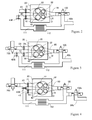
- FIG. 1 (A) is a plan view of a schematic block diagram of a four-cylinder six-cycle engine provided with a regenerator based on the first means for solving problems.
- An exhaust turbine 100 constituting a regenerator is secured to an exhaust manifold 80 of a non-supercharged six-cycle engine 1.
- the exhaust turbine 100 converts pressure remaining in exhaust fume into rotating energy, and then discharges gas containing lowered pressure to the atmosphere via an exhaust manifold 80b disposed on the downstream side of the regenerator.
- FIG. 1 (B) is a graphic chart (this will be referred to as a PV line chart hereinafter) that illustrates variation of the volume and the pressure inside a fuel combustion chamber during a compression stroke and an explosion/expansion stroke of a non-supercharged four-cycle engine and the engine based on the first means for solving problems.
- the dotted line corresponds to a PV line when a compressive ratio is 9.5 with a premixed combustion type four-cycle engine.
- the height at a point A1 designates suction pressure that is equal to atmospheric pressure, and the position of the lateral axis designates the inner volume of a cylinder when a piston is positioned at a lower dead center.
- Variation of the volume and the pressure during an adiabatic compression process in the course of the rise of the piston is shown by a curved line that rises to the left in a range from point A1 up to point A2.
- an ignition takes place, and then, pressure inside the cylinder is raised up to point A3 due to the rise of temperature therein. Then, as a result of the descending movement of the piston, combusted fuel gas expands in an adiabatic condition.
- the internal pressure reaches point A4.
- the exhaust valve opens, combusted gas remaining in the fuel combustion chamber freely expands down to point A1 corresponding to the atmospheric pressure.
- Differential pressure between the points A4 and A1 indicates the presence of pressure energy that is released without being collected via free expansion that occurs when the exhaust valve is open. Thenceforth, after completing an exhaust stroke and a suction stroke, the process returns to the point at A1 to terminate one cycle operation.
- the solid line indicates a PV line of a six-cycle engine provided with a regenerator that has an identical displacement with 12.2 of the compressive ratio.
- the PV line shown in the chart includes a compression stroke, an explosion/expansion stroke and another expansion stroke executed inside the regenerator.
- the difference in the compression ratio of the six-cycle engine from that of a four-cycle engine is caused by a fact that gas temperature at the end of an suction stroke of the six-cycle engine is lower than that of the four-cycle engine because the six-cycle engine is subject to an internal cooling process with scavenging air.
- a gas compression stroke begins at point B1.
- FIG. 2 is a schematic block diagram of an exhaust gas recirculation (EGR) system provided for the six-cycle engine, which corresponds to the second means for solving problems, in which a fuel combustion chamber in a cylinder head 20 built in this multiple cylinder engine according to this embodiment is viewed from the cylinder side.
- FIG. 2 shows a poppet type suction valve 22, a scavenging valve 42, an exhaust valve 32, and a nozzle portion of a direct-injection injector 18, which are collectively disposed in the fuel combustion chamber.
- the above fuel combustion chamber has a plurality of small-size exhaust valves 32. This is because, as described on FIG.
- the timing for opening the exhaust valves during the exhaust of scavenging air stroke is short (between point D8 and point D6 as shown in FIG. 5 ), and thus, it is necessary to open and close all the exhaust valves as fast as possible.
- a cooling unit 112 is disposed inside the gas passage 111.
- the second valve 43 regulates the volume of scavenging air, whereas a scavenging valve regulates the volume of fresh air mixed into scavenging air.
- FIG. 3 is a schematic block diagram of an exhaust gas recirculation (EGR) system built in the six-cycle engine provided with a supercharger, which corresponds to the second embodiment of the second means for solving problems according to the present invention.
- EGR exhaust gas recirculation
- Only the suction port of the six-cycle engine is provided with a supercharger 200.
- the EGR system equipped with the supercharger 200 deals with pressure that is higher than the exhaust gas pressure passing through the scavenging port. Due to lower pressure of scavenging air, the scavenging air is compressed during a exhaust of scavenging air stroke inside the six-cycle engine, and then expelled to the exhaust port.
- Weight of the scavenging air decreases compared to suction air to the extent that the pressure is low
- the temperature rises.
- scavenging air cools off the interior of the fuel combustion chamber with a temperature lower than that of compressed air. And this provides an advantage of dispensing with a supercharger for scavenging air.
- FIG. 4 is a schematic block diagram of an EGR system provided for the six-cycle engine equipped with a supercharger according to the above third embodiment based on the second means for solving problems.
- a couple of regenerators 100 and 100B are disposed in series, and in addition, a gas passage 111 is formed for circulating exhaust gas between the regenerators 100 and 100B with a cooling unit 112 installed in the passage.
- the cooling unit 112 cools off exhaust gas that has been expanded up to the atmospheric pressure, and then the cooled exhaust gas is again supercharged for use.
- the fourth embodiment intensifies the pressure of suction air to be higher than the pressure of the scavenging air.
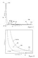
- FIG. 5 is a PV diagram of an independent six-cycle diesel engine that is supercharged with 4 barometric pressure and equipped with a supercharger and a regenerator based on the fourth means for solving problems according to the present invention.
- the diagram explains variation of power output from a single six-cycle engine unit caused by difference in the regenerative pressure.
- the solid line illustrates a PV line chart of a single six-cycle engine unit when an ideal regenerative pressure is used.
- the dotted line illustrates a PV line chart when the regenerative pressure has been lowered than the ideal regenerative pressure.
- a compression stroke is initiated from the point D1 that designates a supercharged pressure.
- the point D2 is reached when pistons reaches upper dead center via adiabatic compression during compression stroke.
- the PV line separates into a solid line and a dotted line.
- the following explanation refers to the case of an ideal regenerative pressure shown by the solid line.
- a piston expels exhaust gas under the ideal regenerative pressure until it reaches upper dead center or point D6.
- a scavenging valve opens itself at the point D7 at a later moment.
- the gas pressure remaining inside the fuel combustion chamber at the upper dead center corresponds to the regenerative pressure that is higher than the scavenging pressure, and thus, when the scavenging valve opens at the upper dead center, exhaust gas remaining in the fuel combustion chamber reversely flows to the scavenging port.
- a higher combustion efficiency and less noise generation can be secured by making exhaust gas expand inside the fuel combustion chamber.
- Piston pushes the scavenging air to expel until it reaches the upper dead center point D6 under the regenerative pressure, the exhaust of scavenging air stroke ends, and the exhaust valve is closed.
- the piston starts to descend, and then, after a while, the suction valve opens itself at the point D7.
- the fresh suction air is admitted to cylinder and the piston reaches the lower dead center point D1, then the suction process ends and the suction valve is closed, and one cycle is completed.
- the area surrounded by the points D1, D8, D2, D3, D3b, and D4 designates energy that is converted from combusted gas into rotational power of the above six-cycle engine during the compression stroke and the explosion/expansion stroke.
- the energy shown by the area surrounded by the points D4, D6, D7, and D1 is taken from the engine rotating power.
- energy shown by the area surrounded by solid lines interlinking the points D1, D8, D6, and D7 is taken from the engine rotating power during the exhaust of scavenging air stroke and the suction stroke.
- practical energy that can be output via single cycle of the six-cycle engine corresponds to the result of subtraction of an area that doubles the area surrounded by solid lines interlinking the points D1, D8, D6, and D7 from the area surrounded by solid lines interlinking the points D4, D8, D2, D3, and D3b.
- Dotted line illustrates such a case in which the regenerative pressure is lowered to one half of the ideal regenerative pressure.
- the scavenging air begins being compressed,
- the exhaust valve is again opened at the point D8b to expel the scavenging air to the exhaust port.
- the piston pushes the scavenging air to expel with regenerative pressure, and then reaches the point D6b.
- the piston begins to descend itself and at a time slightly later on, the suction valve is opened at the point D7b.
- the suction stroke ends, and the suction valve is closed, then one cycle is completed.
- the energy output from the six-cycle engine via single cycle corresponds to the result from a subtraction of the area that doubles the area surrounded by the solid lines and the dotted lines each interlinking the points D1, D8b, D6b, and D7b, from the area surrounded by the solid lines and the dotted lines each interlinking the points D5, D8b, D2, D3, D3b, D4, and D5.
- FIG. 5 shows that the power output from a single unit of the six-cycle engine rises by 35% when the regenerative pressure is reduced into one half. Practically, efficiency in the exchange of exhaust air with fresh air is higher when the regenerative pressure remains low This in turn makes it possible to supply an increased volume of fuel, thus resulting in the enhanced power output from the six-cycle engine furthermore.
- FIG. 6(A) is a PV diagram of the whole unit of the six-cycle engine including a supercharger and a regenerator cited above.
- FIG. 6(B) is an enlarged view in the periphery of the original point. Fresh air fed into the supercharger at the atmospheric pressure G1 is then supercharged and turned into the pressure G2. The six-cycle engine draws the supercharged fresh air at the pressure corresponding to the point D1, and then, after passing through the process described in reference to FIG. 5 , the exhaust valve opens itself at the point D4.
- FIG. 6(A) presents a PV line chart comprising a solid line, a dotted line, and a two-dot chained line.
- the solid line is of the case of using the ideal regenerative pressure that corresponds to the solid-line graphic chart shown in FIG. 5 .
- Exhaust gas expelled from the six-cycle engine at the pressure shown at the point D4 directly becomes the pressure G3 at the inlet of the regenerator, which is then subject to a adiabatic expansion continuously inside the regenerator before being exhausted to the atmosphere at the atmospheric pressure G4.
- the regenerator collects the energy required in the course of the introduction of scavenging air stroke and the exhaust of scavenging air stroke by directly converting the above energy into the rotating energy, and thus, this energy is not shown in FIG. 6(A) and (B) .
- a larger volume of gas flows into the regenerator because of the above reason, resulting in lower gas temperature.
- the energy to be output from the whole unit of the engine per cycle is designated by an area surrounded by solid lines interlinking the points G1, D1, D2, D3, D3b, D4, and G4.
- the dotted line corresponds to the case of the dotted line shown in FIG. 5 .
- gas inside the fuel combustion chamber freely expands up to the regenerative pressure G3b. Since the extent of the lowered temperature is less than the case in which gas adiabatically expands from the ideal regenerative pressure while doing work inside the regenerator, actual volume at the above pressure is greater than the case in which gas expands inside the regenerator at the ideal regenerative pressure, thus causing the point G3b to be positioned to the right of solid line.
- Exhaust gas expelled from the six-cycle engine by the pressure at the point D5 directly becomes the pressure G3b at the inlet of the regenerator, and then, the exhaust gas is subject to adiabatic expansion continuously inside the regenerator before being exhausted to the atmosphere at point G4b at atmospheric pressure.
- the energy that can be output per cycle is designated by an area surrounded by solid lines interlinking the points G1, D1, D2, D3, D3b, D4, D5, G3b, and G4b.
- the energy (corresponding to the area on the left side of a dotted line interlinking the point G3b with the point G4b) that can be regenerated by the regenerator is less than the case (an area on the left side of a solid line interlinking the point G3 with the point G4) of the ideal regenerative pressure.
- this cycle is fully workable on the industrial basis. This is because that since the freely expanded pressure energy is not simply released, but the released energy has merely been converted into gas thermal energy, thus it is possible to regenerate much of the gas thermal energy via a regenerator.
- the six-cycle engine with a regenerator Since it is possible to vary the proportion between the power output from a single unit of the six-cycle engine and the power output from the regenerator with less variation of efficiency of the thermal cycles between the solid line and the dotted line, the six-cycle engine with a regenerator has an advantage when being required to independently control the power output from a couple of output shafts.
- Two-dot chained line shows the PV line chart in the case in which a regenerative pressure is identical to a supercharging pressure.
- the decline of the overall efficiency caused by variation of the regenerative pressure is proportional to a quadric against the difference from the pressure based on a maximum efficiency.
- overall efficiency will be lowered by 11%.
- actual load at cruising speed is considerably lower than full load, so it is not necessarily denied for industrial applicability to use such pressure value as set pressure of a regenerator for full load condition.
- the regenerative pressure also can be set at a value slightly higher than the inner pressure of cylinder which is the pressure when the exhaust valve of the above six-cycle engine is opened.
- the inner pressure of cylinder which is the pressure when the exhaust valve of the above six-cycle engine is opened.
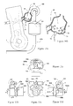
- FIG. 7 is a schematic block diagram that illustrates the first embodiment of the present invention based on the fourth means for solving problems.
- a scrolling type displacement type expander functioning as a regenerator 100 is secured to an exhaust manifold 80 of a six-cycle engine 1. Power output from the regenerator 100 is transmitted to the six-cycle engine 1 via a transmission 180 and a power transmitting belt 181.
- a dotted-line circle drawn in the regenerator 100 designates the exhaust manifold 80b that is disposed below thereof and emits exhaust gas from the expander.
- the transmission 180 remains at the least ratio, the six-cycle engine adopts the ideal regenerative pressure.
- gas volume drawn by the regenerator 100 increases by more than the volume of exhaust gas expelled by the six-cycle engine.
- an exhaust valve of the six-cycle engine opens, exhaust gas freely expands, and then turns into such a regenerative pressure lower than the ideal regenerative pressure.
- the gas expansion ratio inside the expander becomes a steady value. It is therefore preferable not to vary the regenerative pressure from the viewpoint of stabilizing practical efficiency of the regenerator and the exhaust noise. Hence, it is so arranged that the transmission be held by bigger ratio while fully being loaded so as to provide the regenerative pressure to be lower than the ideal regenerative pressure as shown by the dotted line in FIG. 6 . Conversely, when partial load is applied, operating ratio of the transmission is smaller so that exhaust gas can be regenerated by applying the ideal regenerative pressure.
- FIG. 8 is a schematic block diagram that illustrates the second embodiment of the present invention based on the fourth means for solving problems.
- An exhaust manifold 80 of the six-cycle engine 1 is provided with a turbine-type regenerator 100 that drives an electricity generator 151 and an auxiliary unit 150 that are respectively disposed coaxially.
- a variable vane type turbine or a turbine with variable number of nozzles make it possible to control an overall area of nozzles, thereby properly controlling the regenerative pressure.
- By controlling the overall area of nozzles into a proper extent in proportion to the volume of exhaust gas emitted from the six-cycle engine it is possible to constantly maintain the regenerative pressure at a value close to that of the ideal regenerative pressure.
- by intentionally controlling the regenerative pressure so as to further expand the aperture area of nozzles, it is possible to properly drive the six-cycle engine with a regenerative pressure lower than the ideal regenerative pressure.
- a waste gate valve 35 is secured to the exhaust portion of the six-cycle engine so as to release exhaust gas into the atmosphere.
- operating efficiency is lowered.
- the pressure at the inlet of the above regenerator is provisionally lowered, if the descending period merely lasts for a short period, it is possible to maintain the rotating speed of the turbine by temporarily lowering load torque held by the power generator.
- This system can be applied to such a case in which it is desired to quickly raise the rotational number of the six-cycle engine so as to boost an overall power output from this engine because of its less time lag in accelerating.
- This system is advantageous for use as a motor for driving such a movable object such as a vehicle having a greatly variable load.
- the six-cycle engine 1 is equipped with a supercharger 200 that is driven by a motor 250, in which the supercharging pressure can be controlled via an external source. So it is arranged that the power to be output from the whole system can be controlled by supercharged pressure.
- the turbine according to the present embodiment deals with the supersonic, it is so controlled that a constant regenerative pressure can remain being lower than the ideal regenerative pressure when fully being loaded. Hence, there is such an advantageous effect capable of constantly maintaining the engine operating efficiency at a high degree while simplifying the regenerating system.
- FIG. 9 is a schematic block diagram of a six-cycle gas turbine according to the seventh embodiment of the present invention based on the fifth means for solving problems.
- the power output from a six-cycle engine 1 drives a supercharger 200 that is a turbine-type compressor via an accelerator 280 and also drives an auxiliary unit 150 via a belt 154.
- Majority of the power is output from a turbine 100 functioning as a regenerator, and then converted into electric power by an electric generator 151.
- FIG. 10 is a lateral view of a six-cycle engine provided with multiple cylinders disposed in series, which is further provided with a combustion chamber (based on the seventh means for solving problems) that is disposed inside an exhaust manifold 80 based on the third means for solving problems.
- the combustion chamber 70 is disposed inside the assembled portion of the exhaust manifold 80 linked with exhaust ports 31 of individual cylinders disposed inside the six-cycle engine. Including external periphery of an exhaust turbine, the exhaust manifold 80 provided with the combustion chamber 70 therein is fully covered with heat insulating material 71. The inner surface of the exhaust manifold 80 is covered with heat insulating coating material.
- a regenerator 100 is linked with the down-stream side of the combustion chamber 70, and further, an exhaust catalyst unit 63 is disposed inside the other exhaust manifold 80b set to the downstream portion of the regenerator 100.
- An inner wall 72 with a plurality of gas-passing through holes 73 is formed inside the combustion chamber 70.
- the combustion chamber 70 intermixes exhaust gas generated via fuel combustion with scavenging exhaust gas incoming alternately, and then combusts unburned gas.
- a fuel injecting port of a fuel feeder 75 is disposed inside the combustion chamber 70, which feeds fuel to the combustion chamber 70 as required.
- the fuel feeding unit is disposed projecting downward.
- FIG. 11 is a four orthogonal view of a power plant mounted on a hybrid system FF (Front-engine Front-drive) vehicle provided with a laterally disposed engine based on the ninth and eleventh means for solving problems according to the present invention.
- the six-cycle engine conforms to the engine that has introduced the third, sixth, and the seventh means for solving problems related to the present invention.
- FIG. 11 (A) is a front view of the power plant as seen from the front of the above-referred vehicle.
- FIG. 11 (B) is a lateral view thereof.
- FIG. 11 (C) is an upper-surface view thereof.
- FIG. 11 (D) is a rear view thereof.
- the six-cycle engine 1 is a 90-degree V-shaped four-cylinder engine that is independently provided with a scavenging air port and an suction port therein.
- the six-cycle engine 1 is further provided with a scrolling type displacement type compressor 210 as a supercharger that is directly linked with a crank shaft.
- the supercharger 210 feeds intake fresh air to the suction port of the six-cycle engine with a stable pressure by such a volume proportional to the rotational number of the above six-cycle engine. Since the compression ratio of the above displacement type compressor 210 is in the range from two to three, this in turn makes it possible to compactly configure the six-cycle engine. Actual supercharging pressure rises higher than said value of the compression ratio because of increased temperature due to adiabatic compression.
- the 90-degree V-shaped four cylinder six-cycle engine is disposed in the direction slightly inclined backwards.
- a combustion chamber 70 equipped with a fuel feeder 75 is disposed in a portion assembled with a specific number of thermally insulated exhaust manifolds extended from exhaust ports of individual cylinders.
- a regenerator 100 that is a turbine with variable number of nozzles is disposed above the combustion chamber 70.
- An electric generator 151 is secured to an output shaft of the regenerator 100 in order to convert the power output from the six-cycle engine 1 into electric power.
- exhaust gas is led to an exhaust-catalyst unit disposed in a forward location. Exhaust gas is then led in the downward direction in front of the six-cycle engine, and then led in the backward direction along the bottom surface of the vehicle chassis.
- the ninth embodiment provides an EGR system that corresponds to the one introduced for the third embodiment. After flowing from the upper-stream portion of the catalyst, exhaust gas circulates around the catalyst so as to maintain inner temperature thereof, the exhaust gas is cooled off by a cooling device 112 of the EGR system corresponding to one-point chained line shown in FIG. 10 (a) , and then led to a scavenging port of the six-cycle engine 1.
- An electric generator that also serves as a motor 155 functioning as an auxiliary unit is directly secured to the output shaft of the six-cycle engine 1. Availing of surplus power output from the six-cycle engine, electric power is generated by the generator 155, which is then stored in a battery in combination with electric power generated by another generator 151. The electric power is used for driving a motor 550 for driving the vehicle.
- the engine power is mainly output from the above-referred regenerator 100. Since the six-cycle engine merely drives the supercharger 200 as an auxiliary unit and the motor 155 that also serves as a generator, this operating system is regarded as a kind of a six-cycle gas turbine.
- the vehicle mounted with the six-cycle engine converts the power output from the motor 155 into a proper rotational number via a transmission gear 520, which enables the vehicle to run by driving the front wheels via a couple of drive shafts 522 and 522b.
- the motor 550 and the transmission gear 520 are designated with one-point chained line, respectively.
- the power plant according to the ninth embodiment of the present invention enables to contracts the width of the engine via the method of supercharging and arranging the engine configuration into the V-shape.
- the power generator 155 can be designed to have its shorter width because it is only necessary to secure such a torque required for starting the engine. These means make it possible to further mount the vehicle-driving motor 550 along the power generating motor 155.
- Another power generator 151 features the high rotational number and is capable to be configured with compact dimensions. So this power plant can advantageously be used for any of compactly built cars.
- FIG. 12 is a diagram of the controlling system according to the ninth embodiment of the present invention.
- the vehicle-driving motor 550 is driven by a motor controller 560 in conformity with an accelerator sensor 24 so that the vehicle can properly be subject to acceleration and deceleration.
- Controlling computer 610 has a means for sensing the actually charged volume of DC power stored in a battery 580 and a function for operating a rotary actuator 360 that rotates a switching valve for varying the number of nozzles provided for a turbine with variable number of nozzles. By referring to an actually charged volume stored in a battery being detected, the controlling computer 610 determines the rotational number of the six-cycle engine 1 required for determining a practical volume of DC power to be generated. By mainly controlling the number of nozzles built in the exhaust turbine, the controlling computer 610 varies the regenerative pressure and properly controls the rotational number of the six-cycle engine 1.
- the regenerative pressure is lowered to cause the power output from the six-cycle engine to be increased, thereby increasing the rotational number of the six-cycle engine resulting in the enhanced power output from the whole engine unit.
- the controlling computer 610 controls a motor controller 560, and then, availing of a specific rate of power generated by the power generator 155 that concurrently serves as a motor, the actual load borne by the six-cycle engine is varied so as to properly regulate the rotational number thereof.
- the ninth embodiment does not use a throttle valve. If it is no longer necessary to generate power, the controlling computer 610 suspends further supply of fuel, and then boosts the actual load applied to the motor 155 to terminate operation of the six-cycle engine. Re-start of the six-cycle engine is also executed by the power generator that concurrently serves as the motor 155.
- the controlling computer 610 has a means for sensing signal output from an exhaust sensor 68 for sensing actual condition of the built-in catalyst.
- the controlling computer 610 also has means for operating an actuator 91 that individually opens and closes the second valve and a scavenging port valve respectively secured to the scavenging port and a scavenging port valve actuator 94.
- the actuator 91 opens the second valve so as to increase the exhaust gas volume. If it is identified that oxygen has a higher density, the scavenging port valve is operated in the direction of the closed position.
- FIG. 13 is a schematic block diagram of a motive power system built in a movable body based on the eighth means for solving problems according to the present invention.
- the reference numeral 1 designates a six-cycle engine provided with a regenerator, wherein the six-cycle engine comprises four cylinders disposed in series and is equipped with a supercharger 200.
- a gas turbine has been introduced so as to function as a regenerator 100.
- the power output from the regenerator 100 is converted into electric power by an electric generator 151, and then, the electric power is further converted into a proper voltage and a proper frequency suitable for driving a vehicle driving motor with a motor controller 560, which is then converted into a driving power via a motor 550 and then further converted into a proper rotational number via a transmission gear 520.
- the driving power with a proper rotational number of the motor 520 is then transmitted to a couple of driving wheels 525 and 525b via a couple of drive shafts 522 and 522b.
- the output shaft of the six-cycle engine 1 is also connected to the motor 550.
- the power output from the six-cycle engine 1 is transmitted to the drive shaft via the transmission gear 520 in combination with the power output from the motor.
- the six-cycle engine 1 is provided with a supercharger 200 that is driven with a motor 250, in which the rotational number of the supercharger 200 is controlled by the motor controller 560 in accordance with the instructions of the operator.
- the motor controller properly controls the power output from the six-cycle engine by applying the supercharging pressure.
- a portion of the power output from the regenerator drives an auxiliary unit 150 such as a compressor of an air conditioner operated via a speed reduction gear 152 and a clutch 153.
- a battery 580 is installed. Since the battery only needs such an energy just enough to accelerate the supercharger 200, it is not always necessary to provide the battery with a size appropriate for a hybrid vehicle.
- auxiliary unit is driven by a regenerator, it is no longer necessary to provide the drive belt 154 shown in FIG. 9 otherwise needed for driving the auxiliary unit.
- This in turn enables the total length of the six-cycle engine 1 to be contracted proportionally, thereby proving such an advantage capable of securing enough space for accommodating the motor 550 for driving a hybrid vehicle therein.
- FIG. 14 is a schematic block diagram that illustrates the disposed direction of cylinders built in a six-cylinder engine provided with W-shaped six cycles and also illustrates the crank pins disposed therein.
- One-dot chained lines a, b, and c respectively designate the center lines inside the three cylinder blocks that are arranged into the W shape.
- the reference numeral 51 designates a piston that reciprocates inside an individual cylinder via sliding.
- the pistons 51a1, 51b1, and 51c1 designated by solid lines individually correspond to the crank pins disposed in a single unit of the W-shaped bank, where the crank pins are respectively designated at positions that correspond to the positions of individual pins 50a1, 50b1, and 50c1.
- crank pins 50a2, 50b2, and 50c2 and those pistons 51a2, 51b2, and 51c2, respectively being designated by dotted lines respectively show the position of the other unit of the W-shaped bank.
- the positions of the crank pins disposed against a couple of pistons present in a single cylinder block are 180 degrees out of phase, making a six-cycle engine having 180 degree equal interval combustion with primary balance including the moment of inertia.
- the number of the bearing provided for an individual crank is set to be three bearings that are disposed on both sides for three crank pins per unit of the W-shaped bank or alternatively four bearings that are disposed per couple of crank pins upon consideration of the rigidity and strength of individual cranks.
- the above six-cycle engine consisting of the W-shaped six cylinders according to the eleventh embodiment is provided with a constant length in the direction of the vehicle width, and yet, the above six-cycle engine is replaceable.
- the above six-cycle engine provided with a regenerator according to the present invention is extensively applicable to every end-use that requires an internal combustion engine with improved fuel cost economy.
- the primary object of the present invention is to ensure an effective utilization of residual energy remaining in the exhaust gas discharged from a displacement type engine via regeneration of the exhaust gas in a simple way, thereby contributing to improve the fuel cost economy.
- the invention advantageously suppresses noise generated from exhaust gas.
- the six-cycle engine with a regenerator does not cause the working efficiency to lower even when being supercharged with a relatively high pressure and is capable of generating substantial advantage from the compact configuration in the exhaust gas supercharging process.
- the invented 6-cycle gas turbine is also available as a gas turbine with easy controllability.
Landscapes
- Engineering & Computer Science (AREA)
- Mechanical Engineering (AREA)
- General Engineering & Computer Science (AREA)
- Combustion & Propulsion (AREA)
- Chemical & Material Sciences (AREA)
- Output Control And Ontrol Of Special Type Engine (AREA)
- Supercharger (AREA)
- Valve Device For Special Equipments (AREA)
- Electrical Control Of Air Or Fuel Supplied To Internal-Combustion Engine (AREA)
- Exhaust-Gas Circulating Devices (AREA)
- Exhaust Gas After Treatment (AREA)
- Combined Controls Of Internal Combustion Engines (AREA)
- Control Of Turbines (AREA)
- Valve-Gear Or Valve Arrangements (AREA)
- Control Of Throttle Valves Provided In The Intake System Or In The Exhaust System (AREA)
Applications Claiming Priority (2)
| Application Number | Priority Date | Filing Date | Title |
|---|---|---|---|
| JP2006248694A JP2006348947A (ja) | 2006-08-18 | 2006-08-18 | 排気圧回生機付内燃機関 |
| PCT/JP2007/065334 WO2008020550A1 (fr) | 2006-08-18 | 2007-08-06 | Moteur à six temps avec régénérateur |
Publications (1)
| Publication Number | Publication Date |
|---|---|
| EP2053214A1 true EP2053214A1 (de) | 2009-04-29 |
Family
ID=37645029
Family Applications (2)
| Application Number | Title | Priority Date | Filing Date |
|---|---|---|---|
| EP07790815A Withdrawn EP2053215A1 (de) | 2006-08-18 | 2007-07-16 | Abgaskatalysatorsteuerung für sechstaktmotor |
| EP07792007A Withdrawn EP2053214A1 (de) | 2006-08-18 | 2007-08-06 | 6-takt-motor mit regenerator |
Family Applications Before (1)
| Application Number | Title | Priority Date | Filing Date |
|---|---|---|---|
| EP07790815A Withdrawn EP2053215A1 (de) | 2006-08-18 | 2007-07-16 | Abgaskatalysatorsteuerung für sechstaktmotor |
Country Status (10)
| Country | Link |
|---|---|
| US (3) | US20100083921A1 (de) |
| EP (2) | EP2053215A1 (de) |
| JP (5) | JP2006348947A (de) |
| KR (2) | KR20090042287A (de) |
| CN (3) | CN101506497A (de) |
| BR (1) | BRPI0715700A2 (de) |
| CA (2) | CA2658788A1 (de) |
| MX (2) | MX2009001352A (de) |
| RU (2) | RU2009101965A (de) |
| WO (4) | WO2008020498A1 (de) |
Cited By (6)
| Publication number | Priority date | Publication date | Assignee | Title |
|---|---|---|---|---|
| GB2513432A (en) * | 2013-04-26 | 2014-10-29 | Controlled Power Technologies Ltd | Generation of electricity from exhaust gas |
| EP2808517A4 (de) * | 2012-01-27 | 2014-12-03 | Yamaha Motor Co Ltd | Sechstaktmotor mit spülhub |
| EP2808516A4 (de) * | 2012-01-27 | 2014-12-03 | Yamaha Motor Co Ltd | Sechstaktmotor mit spülhub |
| DE102015216830A1 (de) * | 2015-09-03 | 2017-03-09 | Volkswagen Aktiengesellschaft | Verfahren sowie Vorrichtung zur Abgasnachbehandlung einer Brennkraftmaschine |
| DE112013007493B4 (de) * | 2013-10-11 | 2021-05-06 | Shigeru Sato | Verbrennungsmotor für ein Hybrid-Antriebssystem und ein solches Antriebssystem |
| NL2028576B1 (en) * | 2021-06-29 | 2023-01-09 | Daf Trucks Nv | Internal combustion engine arranged for conducting a six-stroke internal combustion process. |
Families Citing this family (68)
| Publication number | Priority date | Publication date | Assignee | Title |
|---|---|---|---|---|
| JP2006348947A (ja) * | 2006-08-18 | 2006-12-28 | Kazuo Oyama | 排気圧回生機付内燃機関 |
| JP4894733B2 (ja) * | 2007-11-16 | 2012-03-14 | マツダ株式会社 | 水素エンジンを用いたコージェネレーションシステム |
| DE102007056889A1 (de) * | 2007-11-26 | 2009-05-28 | Bosch Mahle Turbo Systems Gmbh & Co. Kg | Abgasturbolader mit mindestens einer Turbine variabler Turbinengeometrie |
| CN101787933B (zh) * | 2010-01-21 | 2013-01-09 | 上海交通大学 | 阿特金森循环发动机控制系统及其控制方法 |
| CN101737187A (zh) * | 2010-01-21 | 2010-06-16 | 上海交通大学 | 阿特金森循环发动机空燃比控制系统 |
| US20120144764A1 (en) * | 2010-11-10 | 2012-06-14 | James Hanna | Cellulose construction system |
| US9109614B1 (en) | 2011-03-04 | 2015-08-18 | Lightsail Energy, Inc. | Compressed gas energy storage system |
| US8904786B2 (en) * | 2011-04-13 | 2014-12-09 | GM Global Technology Operations LLC | Internal combustion engine |
| CN102410085A (zh) * | 2011-06-15 | 2012-04-11 | 靳北彪 | 六冲程发动机 |
| US8613267B1 (en) * | 2011-07-19 | 2013-12-24 | Lightsail Energy, Inc. | Valve |
| FR2978209B1 (fr) * | 2011-07-21 | 2013-07-12 | IFP Energies Nouvelles | Procede de detection et de caracterisation de combustion anormale pour moteurs a combustion interne |
| JP2015500411A (ja) | 2011-10-18 | 2015-01-05 | ライトセイル エナジー インコーポレイテッド | 圧縮気体エネルギー貯蔵システム |
| US8978602B2 (en) | 2012-12-12 | 2015-03-17 | Caterpillar Inc. | Six-stroke engine power density matching system and method |
| US8978603B2 (en) * | 2012-12-12 | 2015-03-17 | Caterpillar Inc. | Six-stroke internal combustion engine valve activation system and method for operating such engine |
| US8978601B2 (en) | 2012-12-12 | 2015-03-17 | Caterpillar Inc. | Six-stroke engine system with blowdown exhaust system |
| US9151222B2 (en) | 2012-12-12 | 2015-10-06 | Caterpillar Inc. | Six-stroke combustion cycle engine and process |
| US9181830B2 (en) | 2012-12-12 | 2015-11-10 | Caterpillar Inc. | After-treatment system and method for six-stroke combustion cycle |
| US9057324B2 (en) * | 2012-12-12 | 2015-06-16 | Caterpillar Inc. | Six-stroke engine system with blowdown turbocharger |
| US9133764B2 (en) | 2012-12-12 | 2015-09-15 | Caterpillar Inc. | Six-stroke engine system with blowdown exhaust recirculation |
| US9500122B2 (en) | 2013-06-28 | 2016-11-22 | General Electric Company | Variable geometry nozzle and associated method of operation |
| CN103615306A (zh) * | 2013-11-29 | 2014-03-05 | 东风小康汽车有限公司重庆分公司 | 涡轮增压装置 |
| US10197473B2 (en) * | 2015-12-09 | 2019-02-05 | General Electric Company | System and method for performing a visual inspection of a gas turbine engine |
| KR101831838B1 (ko) * | 2016-12-15 | 2018-02-23 | 한국에너지기술연구원 | 로터부의 충격하중 저하를 위한 부분분사운전 터빈장치 |
| KR101831837B1 (ko) | 2016-12-15 | 2018-02-23 | 한국에너지기술연구원 | 상시 부분분사운전 효율 향상을 위한 부분분사운전 터빈장치 및 이를 이용한 터빈장치 작동방법 |
| US10138805B2 (en) * | 2017-03-03 | 2018-11-27 | Chi Keng Chen | Six-stroke and eight-stroke internal combustion engines |
| JP6677202B2 (ja) * | 2017-03-28 | 2020-04-08 | トヨタ自動車株式会社 | インテークマニホールド |
| US11624326B2 (en) | 2017-05-21 | 2023-04-11 | Bj Energy Solutions, Llc | Methods and systems for supplying fuel to gas turbine engines |
| JP7348715B2 (ja) * | 2018-04-26 | 2023-09-21 | 株式会社三井E&S Du | エンジンシステム |
| US11560845B2 (en) | 2019-05-15 | 2023-01-24 | Bj Energy Solutions, Llc | Mobile gas turbine inlet air conditioning system and associated methods |
| US11015594B2 (en) | 2019-09-13 | 2021-05-25 | Bj Energy Solutions, Llc | Systems and method for use of single mass flywheel alongside torsional vibration damper assembly for single acting reciprocating pump |
| US10989180B2 (en) | 2019-09-13 | 2021-04-27 | Bj Energy Solutions, Llc | Power sources and transmission networks for auxiliary equipment onboard hydraulic fracturing units and associated methods |
| CA3191280A1 (en) | 2019-09-13 | 2021-03-13 | Bj Energy Solutions, Llc | Methods and systems for supplying fuel to gas turbine engines |
| US10895202B1 (en) | 2019-09-13 | 2021-01-19 | Bj Energy Solutions, Llc | Direct drive unit removal system and associated methods |
| US10815764B1 (en) | 2019-09-13 | 2020-10-27 | Bj Energy Solutions, Llc | Methods and systems for operating a fleet of pumps |
| US11002189B2 (en) | 2019-09-13 | 2021-05-11 | Bj Energy Solutions, Llc | Mobile gas turbine inlet air conditioning system and associated methods |
| US11015536B2 (en) | 2019-09-13 | 2021-05-25 | Bj Energy Solutions, Llc | Methods and systems for supplying fuel to gas turbine engines |
| US12065968B2 (en) | 2019-09-13 | 2024-08-20 | BJ Energy Solutions, Inc. | Systems and methods for hydraulic fracturing |
| CA3092859A1 (en) | 2019-09-13 | 2021-03-13 | Bj Energy Solutions, Llc | Fuel, communications, and power connection systems and related methods |
| US12338772B2 (en) | 2019-09-13 | 2025-06-24 | Bj Energy Solutions, Llc | Systems, assemblies, and methods to enhance intake air flow to a gas turbine engine of a hydraulic fracturing unit |
| US10961914B1 (en) | 2019-09-13 | 2021-03-30 | BJ Energy Solutions, LLC Houston | Turbine engine exhaust duct system and methods for noise dampening and attenuation |
| CA3092863C (en) | 2019-09-13 | 2023-07-18 | Bj Energy Solutions, Llc | Fuel, communications, and power connection systems and related methods |
| CA3092865C (en) | 2019-09-13 | 2023-07-04 | Bj Energy Solutions, Llc | Power sources and transmission networks for auxiliary equipment onboard hydraulic fracturing units and associated methods |
| US11555756B2 (en) | 2019-09-13 | 2023-01-17 | Bj Energy Solutions, Llc | Fuel, communications, and power connection systems and related methods |
| US11708829B2 (en) | 2020-05-12 | 2023-07-25 | Bj Energy Solutions, Llc | Cover for fluid systems and related methods |
| US10968837B1 (en) | 2020-05-14 | 2021-04-06 | Bj Energy Solutions, Llc | Systems and methods utilizing turbine compressor discharge for hydrostatic manifold purge |
| US11428165B2 (en) | 2020-05-15 | 2022-08-30 | Bj Energy Solutions, Llc | Onboard heater of auxiliary systems using exhaust gases and associated methods |
| US11208880B2 (en) | 2020-05-28 | 2021-12-28 | Bj Energy Solutions, Llc | Bi-fuel reciprocating engine to power direct drive turbine fracturing pumps onboard auxiliary systems and related methods |
| US11208953B1 (en) | 2020-06-05 | 2021-12-28 | Bj Energy Solutions, Llc | Systems and methods to enhance intake air flow to a gas turbine engine of a hydraulic fracturing unit |
| US10961908B1 (en) | 2020-06-05 | 2021-03-30 | Bj Energy Solutions, Llc | Systems and methods to enhance intake air flow to a gas turbine engine of a hydraulic fracturing unit |
| US11109508B1 (en) | 2020-06-05 | 2021-08-31 | Bj Energy Solutions, Llc | Enclosure assembly for enhanced cooling of direct drive unit and related methods |
| US11111768B1 (en) | 2020-06-09 | 2021-09-07 | Bj Energy Solutions, Llc | Drive equipment and methods for mobile fracturing transportation platforms |
| US10954770B1 (en) | 2020-06-09 | 2021-03-23 | Bj Energy Solutions, Llc | Systems and methods for exchanging fracturing components of a hydraulic fracturing unit |
| US11066915B1 (en) | 2020-06-09 | 2021-07-20 | Bj Energy Solutions, Llc | Methods for detection and mitigation of well screen out |
| US11022526B1 (en) | 2020-06-09 | 2021-06-01 | Bj Energy Solutions, Llc | Systems and methods for monitoring a condition of a fracturing component section of a hydraulic fracturing unit |
| US11933153B2 (en) | 2020-06-22 | 2024-03-19 | Bj Energy Solutions, Llc | Systems and methods to operate hydraulic fracturing units using automatic flow rate and/or pressure control |
| US11939853B2 (en) | 2020-06-22 | 2024-03-26 | Bj Energy Solutions, Llc | Systems and methods providing a configurable staged rate increase function to operate hydraulic fracturing units |
| US11125066B1 (en) | 2020-06-22 | 2021-09-21 | Bj Energy Solutions, Llc | Systems and methods to operate a dual-shaft gas turbine engine for hydraulic fracturing |
| US11028677B1 (en) | 2020-06-22 | 2021-06-08 | Bj Energy Solutions, Llc | Stage profiles for operations of hydraulic systems and associated methods |
| US11473413B2 (en) | 2020-06-23 | 2022-10-18 | Bj Energy Solutions, Llc | Systems and methods to autonomously operate hydraulic fracturing units |
| US11466680B2 (en) | 2020-06-23 | 2022-10-11 | Bj Energy Solutions, Llc | Systems and methods of utilization of a hydraulic fracturing unit profile to operate hydraulic fracturing units |
| US11220895B1 (en) | 2020-06-24 | 2022-01-11 | Bj Energy Solutions, Llc | Automated diagnostics of electronic instrumentation in a system for fracturing a well and associated methods |
| US11149533B1 (en) | 2020-06-24 | 2021-10-19 | Bj Energy Solutions, Llc | Systems to monitor, detect, and/or intervene relative to cavitation and pulsation events during a hydraulic fracturing operation |
| DE102020117321B4 (de) * | 2020-07-01 | 2022-05-19 | Dr. Ing. H.C. F. Porsche Aktiengesellschaft | Abgasturbolader und Kraftfahrzeug |
| US11193361B1 (en) | 2020-07-17 | 2021-12-07 | Bj Energy Solutions, Llc | Methods, systems, and devices to enhance fracturing fluid delivery to subsurface formations during high-pressure fracturing operations |
| KR102726158B1 (ko) * | 2020-07-24 | 2024-11-06 | 로베르트 보쉬 게엠베하 | 전기적으로 지원되는 배기가스 구동식 과급 장치를 구비한 연소 기관을 작동시키기 위한 방법 및 장치 |
| US11639654B2 (en) | 2021-05-24 | 2023-05-02 | Bj Energy Solutions, Llc | Hydraulic fracturing pumps to enhance flow of fracturing fluid into wellheads and related methods |
| US11788460B2 (en) | 2021-08-27 | 2023-10-17 | Garrett Transportation I Inc. | Active surge supression through dynamically controlled actuated turboshaft speed |
| US12378864B2 (en) | 2021-10-25 | 2025-08-05 | Bj Energy Solutions, Llc | Systems and methods to reduce acoustic resonance or disrupt standing wave formation in a fluid manifold of a high-pressure fracturing system |
Family Cites Families (59)
| Publication number | Priority date | Publication date | Assignee | Title |
|---|---|---|---|---|
| US3059415A (en) * | 1959-07-08 | 1962-10-23 | Birmann Rudolph | Turbocharger for internal combustion engines |
| JPS4933014A (de) * | 1972-07-31 | 1974-03-26 | ||
| JPS5447909A (en) * | 1977-09-24 | 1979-04-16 | Masatake Mesaki | 66cylinder internal combustion engine |
| JPS55137305A (en) | 1979-04-13 | 1980-10-27 | Nissan Motor Co Ltd | Valve lift for internal combustion engine |
| JPS5735120A (en) * | 1980-08-11 | 1982-02-25 | Moriyuki Shima | Six-stroke reciprocating engine |
| GB2085146B (en) * | 1980-10-01 | 1985-06-12 | Gen Electric | Flow modifying device |
| US4367700A (en) * | 1981-01-19 | 1983-01-11 | Hotspur International Corporation, Inc. | Apparatus for insuring the complete burning of fuel in a six cycle combustion engine |
| US4577597A (en) * | 1981-06-18 | 1986-03-25 | Honda Giken Kogyo Kabushiki Kaisha | Method and apparatus for supplying fuel to internal combustion engine |
| JPS5818523A (ja) * | 1981-07-23 | 1983-02-03 | Yamaha Motor Co Ltd | 6サイクルエンジン |
| CH654067A5 (fr) | 1982-09-24 | 1986-01-31 | Roger Bajulaz | Moteur a combustion et procede pour sa mise en action. |
| JPS61212632A (ja) * | 1985-03-18 | 1986-09-20 | Mitsubishi Heavy Ind Ltd | タ−ボコンパウンド機関 |
| JPS63215808A (ja) * | 1987-03-03 | 1988-09-08 | Isuzu Motors Ltd | 排気エネルギ−回収装置 |
| BE1000774A5 (fr) * | 1987-07-30 | 1989-04-04 | Schmitz Gerhard | Moteur a combustion interne a six temps. |
| JPS6449525A (en) | 1987-08-20 | 1989-02-27 | Sanyo Electric Co | Floor sucking tool |
| BR8807190A (pt) * | 1987-09-04 | 1989-10-17 | Orbital Eng Pty | Tratamento de gas de escapamento para um motor de dois tempos |
| JPH0196430A (ja) * | 1987-10-07 | 1989-04-14 | Honda Motor Co Ltd | 内燃機関の燃料供給方法及び燃料供給装置 |
| JPH01305129A (ja) * | 1988-06-02 | 1989-12-08 | Nissan Motor Co Ltd | 内燃機関 |
| JPH0296435A (ja) | 1988-10-03 | 1990-04-09 | Hitachi Ltd | キーボード装置 |
| JPH0296435U (de) * | 1989-01-19 | 1990-08-01 | ||
| JP2693552B2 (ja) * | 1989-02-22 | 1997-12-24 | 本田技研工業株式会社 | 内燃機関の動弁機構 |
| JP2819676B2 (ja) | 1989-09-29 | 1998-10-30 | いすゞ自動車株式会社 | 6サイクル断熱エンジン |
| JP2909219B2 (ja) * | 1990-12-05 | 1999-06-23 | マツダ株式会社 | エンジンの暖機装置 |
| JPH04325723A (ja) * | 1991-04-25 | 1992-11-16 | Masahiko Imagawa | 3気筒6サイクル水素エンジン |
| JPH05179913A (ja) | 1991-12-27 | 1993-07-20 | Suzuki Motor Corp | 4サイクルエンジンの可変バルブタイミングリフト装置 |
| DE4238550A1 (de) * | 1992-11-14 | 1994-05-19 | Daimler Benz Ag | Abgasturbolader für eine Brennkraftmaschine |
| DE4330487C1 (de) * | 1993-09-09 | 1995-01-26 | Daimler Benz Ag | Abgasturbolader für eine Brennkraftmaschine |
| JPH08296450A (ja) * | 1995-04-27 | 1996-11-12 | Junichi Nishikubo | シックス・ストロークエンジンの構造 |
| US5699758A (en) * | 1996-02-15 | 1997-12-23 | Caterpillar Inc. | Method and apparatus for multiple cycle internal combustion engine operation |
| JPH09273430A (ja) * | 1996-04-08 | 1997-10-21 | Osamu Nakada | 6サイクルガソリンエンジン。 |
| JP2857666B2 (ja) | 1996-06-12 | 1999-02-17 | 本田技研工業株式会社 | ハイブリッド車両の制御装置 |
| US5802846A (en) * | 1997-03-31 | 1998-09-08 | Caterpillar Inc. | Exhaust gas recirculation system for an internal combustion engine |
| JPH11182272A (ja) * | 1997-12-24 | 1999-07-06 | Osamu Nakada | 4サイクルエンジン、6サイクルエンジン、8サイクルエンジン、10サイクル以上のエンジンに、ピストンバルブ、ロータリーバルブを使用した時の、本当の圧縮比よりも本当の膨張比の方を大きく取る方法。 |
| US6105559A (en) * | 1998-11-18 | 2000-08-22 | General Motors Corporation | Charge proportioning valve assembly |
| JP2000170559A (ja) * | 1998-12-02 | 2000-06-20 | Mitsubishi Motors Corp | 6サイクル内燃機関 |
| US6253745B1 (en) * | 1999-01-26 | 2001-07-03 | David M. Prater | Multiple stroke engine having fuel and vapor charges |
| JP2001012252A (ja) | 1999-06-23 | 2001-01-16 | Mitsubishi Motors Corp | ターボチャージャの制御装置 |
| US6571749B2 (en) * | 1999-12-17 | 2003-06-03 | Satnarine Singh | Computer controlled six-stroke cycle internal combustion engine and its method of operation |
| US7021272B2 (en) * | 1999-12-17 | 2006-04-04 | Satnarine Singh | Computer controlled multi-stroke cycle power generating assembly and method of operation |
| JP2001263110A (ja) * | 2000-03-23 | 2001-09-26 | Nissan Motor Co Ltd | 可変動弁エンジンの制御装置 |
| DE10018303A1 (de) * | 2000-04-13 | 2001-10-25 | Bosch Gmbh Robert | Verfahren zur Füllungssteuerung bei einem Verbrennungsmotor |
| JP4134492B2 (ja) * | 2000-06-08 | 2008-08-20 | 三菱自動車工業株式会社 | 筒内噴射型内燃機関 |
| DE10063750A1 (de) * | 2000-12-21 | 2002-06-27 | Bosch Gmbh Robert | Verfahren und Vorrichtung zum Betreiben einer Brennkraftmaschine |
| US6443108B1 (en) * | 2001-02-06 | 2002-09-03 | Ford Global Technologies, Inc. | Multiple-stroke, spark-ignited engine |
| US6402465B1 (en) * | 2001-03-15 | 2002-06-11 | Dresser-Rand Company | Ring valve for turbine flow control |
| DE10123624A1 (de) * | 2001-05-15 | 2002-11-21 | Bosch Gmbh Robert | Verfahren und Vorrichtung zum Betreiben einer Brennkraftmaschine |
| US6561139B2 (en) * | 2001-10-04 | 2003-05-13 | Evan Guy Enterprises, Inc. | Method and apparatus for reducing emissions of internal combustion engines |
| US6679057B2 (en) * | 2002-03-05 | 2004-01-20 | Honeywell-International Inc. | Variable geometry turbocharger |
| JP3876185B2 (ja) * | 2002-04-26 | 2007-01-31 | 三菱重工業株式会社 | 可変容量タービン及びこれを用いた可変容量ターボチャージャ |
| JP3739725B2 (ja) | 2002-05-31 | 2006-01-25 | 国夫 木下 | 木造建築物における免震構造 |
| CN1415846A (zh) * | 2002-07-08 | 2003-05-07 | 赖大鹏 | 增压横流扫气的排气阀式二冲程柴油机 |
| JP3918717B2 (ja) * | 2002-11-13 | 2007-05-23 | いすゞ自動車株式会社 | エンジンの過給装置 |
| US7013211B2 (en) * | 2002-12-02 | 2006-03-14 | Hitachi, Ltd. | Variable valve control apparatus for internal combustion engine and method thereof |
| US6758170B1 (en) * | 2002-12-18 | 2004-07-06 | Sean Walden | Multi-cycle trainable piston engine |
| AU2003206001A1 (en) * | 2003-02-19 | 2004-09-09 | Honeywell International Inc. | Nozzle device for a turbocharger and associated control method |
| JP4044894B2 (ja) * | 2003-12-17 | 2008-02-06 | マーン・ベー・オグ・ドバルドヴェー・ディーゼール・アクティーゼルスカブ | 単一列の13シリンダーを有する、2ストロークの定圧ターボチャージャー付き内燃エンジン |
| DE202004002185U1 (de) * | 2004-01-28 | 2004-07-22 | Man B & W Diesel A/S | Zweitakt-Verbrennungsmaschine mit Turboladung, konstantem Druck und 14 Zylindern in einer einzigen Reihe |
| JP4135690B2 (ja) | 2004-07-08 | 2008-08-20 | トヨタ自動車株式会社 | ハイブリッド車両 |
| US7143725B1 (en) * | 2005-11-22 | 2006-12-05 | Lung Tan Hu | Dual six-stroke self-cooling internal combustion engine |
| JP2006348947A (ja) * | 2006-08-18 | 2006-12-28 | Kazuo Oyama | 排気圧回生機付内燃機関 |
-
2006
- 2006-08-18 JP JP2006248694A patent/JP2006348947A/ja active Pending
-
2007
- 2007-03-27 JP JP2008529821A patent/JP4255035B2/ja not_active Expired - Fee Related
- 2007-03-27 WO PCT/JP2007/056492 patent/WO2008020498A1/ja not_active Ceased
- 2007-07-16 KR KR1020097004046A patent/KR20090042287A/ko not_active Withdrawn
- 2007-07-16 US US12/377,862 patent/US20100083921A1/en not_active Abandoned
- 2007-07-16 EP EP07790815A patent/EP2053215A1/de not_active Withdrawn
- 2007-07-16 JP JP2008529833A patent/JP4314595B2/ja not_active Expired - Fee Related
- 2007-07-16 CA CA002658788A patent/CA2658788A1/en not_active Abandoned
- 2007-07-16 MX MX2009001352A patent/MX2009001352A/es unknown
- 2007-07-16 CN CNA2007800307130A patent/CN101506497A/zh active Pending
- 2007-07-16 WO PCT/JP2007/064035 patent/WO2008020519A1/ja not_active Ceased
- 2007-07-16 RU RU2009101965/06A patent/RU2009101965A/ru unknown
- 2007-08-06 CN CN2007800307126A patent/CN101506492B/zh not_active Expired - Fee Related
- 2007-08-06 KR KR1020097004053A patent/KR20090045286A/ko not_active Withdrawn
- 2007-08-06 CN CN201110216639XA patent/CN102269058A/zh active Pending
- 2007-08-06 EP EP07792007A patent/EP2053214A1/de not_active Withdrawn
- 2007-08-06 MX MX2009001586A patent/MX2009001586A/es unknown
- 2007-08-06 WO PCT/JP2007/065334 patent/WO2008020550A1/ja not_active Ceased
- 2007-08-06 RU RU2009101964/06A patent/RU2009101964A/ru unknown
- 2007-08-06 JP JP2008529844A patent/JP4298788B2/ja not_active Expired - Fee Related
- 2007-08-06 BR BRPI0715700-2A2A patent/BRPI0715700A2/pt not_active IP Right Cessation
- 2007-08-06 CA CA002658790A patent/CA2658790A1/en not_active Abandoned
- 2007-08-06 US US12/377,861 patent/US8186334B2/en not_active Expired - Fee Related
- 2007-08-17 US US12/377,860 patent/US8821105B2/en not_active Expired - Fee Related
- 2007-08-17 WO PCT/JP2007/066006 patent/WO2008020619A1/ja not_active Ceased
- 2007-08-17 JP JP2008529883A patent/JP4277063B2/ja not_active Expired - Fee Related
Non-Patent Citations (1)
| Title |
|---|
| See references of WO2008020550A1 * |
Cited By (16)
| Publication number | Priority date | Publication date | Assignee | Title |
|---|---|---|---|---|
| US9284892B2 (en) | 2012-01-27 | 2016-03-15 | Yamaha Hatsudoki Kabushiki Kaisha | Six-stroke cycle engine having scavenging stroke |
| US9284883B2 (en) | 2012-01-27 | 2016-03-15 | Yamaha Hatsudoki Kabushiki Kaisha | Six-stroke cycle engine having scavenging stroke |
| EP2808516A4 (de) * | 2012-01-27 | 2014-12-03 | Yamaha Motor Co Ltd | Sechstaktmotor mit spülhub |
| EP2808517A4 (de) * | 2012-01-27 | 2014-12-03 | Yamaha Motor Co Ltd | Sechstaktmotor mit spülhub |
| GB2513776A (en) * | 2013-04-26 | 2014-11-05 | Controlled Power Technologies Ltd | Generation of electricity from exhaust gas |
| GB2513776B (en) * | 2013-04-26 | 2015-04-01 | Controlled Power Technologies Ltd | Generation of electricity from exhaust gas |
| GB2513775A (en) * | 2013-04-26 | 2014-11-05 | Controlled Power Technologies Ltd | Generation of electricity from exhaust gas |
| GB2513432B (en) * | 2013-04-26 | 2015-04-01 | Controlled Power Technologies Ltd | Generation of electricity from exhaust gas |
| GB2513432A (en) * | 2013-04-26 | 2014-10-29 | Controlled Power Technologies Ltd | Generation of electricity from exhaust gas |
| GB2513775B (en) * | 2013-04-26 | 2015-04-01 | Controlled Power Technologies Ltd | Generation of electricity from exhaust gas |
| US9732681B2 (en) | 2013-04-26 | 2017-08-15 | Controlled Power Technologies, Ltd. | Generation of electricity from exhaust gas |
| DE112013007493B4 (de) * | 2013-10-11 | 2021-05-06 | Shigeru Sato | Verbrennungsmotor für ein Hybrid-Antriebssystem und ein solches Antriebssystem |
| DE102015216830A1 (de) * | 2015-09-03 | 2017-03-09 | Volkswagen Aktiengesellschaft | Verfahren sowie Vorrichtung zur Abgasnachbehandlung einer Brennkraftmaschine |
| EP3344863B1 (de) * | 2015-09-03 | 2020-03-18 | Volkswagen AG | Verfahren sowie vorrichtung zur abgasnachbehandlung einer brennkraftmaschine |
| US11002199B2 (en) | 2015-09-03 | 2021-05-11 | Volkswagen Aktiengesellschaft | Method and device for the exhaust-gas aftertreatment of an internal combustion engine |
| NL2028576B1 (en) * | 2021-06-29 | 2023-01-09 | Daf Trucks Nv | Internal combustion engine arranged for conducting a six-stroke internal combustion process. |
Also Published As
| Publication number | Publication date |
|---|---|
| CA2658788A1 (en) | 2008-02-21 |
| CN101506492A (zh) | 2009-08-12 |
| WO2008020498A1 (fr) | 2008-02-21 |
| JP4277063B2 (ja) | 2009-06-10 |
| MX2009001352A (es) | 2009-02-25 |
| US20100278628A1 (en) | 2010-11-04 |
| CA2658790A1 (en) | 2008-02-21 |
| US20100083921A1 (en) | 2010-04-08 |
| CN102269058A (zh) | 2011-12-07 |
| KR20090045286A (ko) | 2009-05-07 |
| WO2008020550A1 (fr) | 2008-02-21 |
| EP2053215A1 (de) | 2009-04-29 |
| CN101506492B (zh) | 2012-01-11 |
| JP4298788B2 (ja) | 2009-07-22 |
| CN101506497A (zh) | 2009-08-12 |
| BRPI0715700A2 (pt) | 2013-08-06 |
| JPWO2008020550A1 (ja) | 2010-01-07 |
| RU2009101964A (ru) | 2010-09-27 |
| WO2008020519A1 (fr) | 2008-02-21 |
| JP2006348947A (ja) | 2006-12-28 |
| JP4314595B2 (ja) | 2009-08-19 |
| JPWO2008020519A1 (ja) | 2010-01-07 |
| RU2009101965A (ru) | 2010-09-27 |
| JP4255035B2 (ja) | 2009-04-15 |
| JPWO2008020498A1 (ja) | 2010-01-07 |
| JPWO2008020619A1 (ja) | 2010-01-07 |
| US20100050963A1 (en) | 2010-03-04 |
| US8186334B2 (en) | 2012-05-29 |
| WO2008020619A1 (fr) | 2008-02-21 |
| US8821105B2 (en) | 2014-09-02 |
| KR20090042287A (ko) | 2009-04-29 |
| MX2009001586A (es) | 2009-02-25 |
Similar Documents
| Publication | Publication Date | Title |
|---|---|---|
| US8186334B2 (en) | 6-cycle engine with regenerator | |
| CN102434326B (zh) | 内燃发动机 | |
| US7231998B1 (en) | Operating a vehicle with braking energy recovery | |
| JP2015522122A (ja) | 可変圧縮比ディーゼルエンジン | |
| US9062632B2 (en) | Internal combustion engine for a motor vehicle | |
| JP2009209809A (ja) | エンジンの過給装置 | |
| KR19990000545A (ko) | 내연기관 과급장치 | |
| RU2623598C1 (ru) | Устройство управления двигателем внутреннего сгорания | |
| US6513484B1 (en) | Boosted direct injection stratified charge gasoline engines | |
| WO2006051299A1 (en) | A pressure-charged gasoline internal combustion engine | |
| EP3596329A1 (de) | Brennkraftmaschine und verfahren zur steuerung solch einer brennkraftmaschine | |
| US20060048981A1 (en) | High output and efficiency internal combustion engine | |
| JP2009191727A (ja) | エンジンの過給装置 | |
| KR20080042149A (ko) | 가변 압축 2행정 엔진 | |
| CN205744123U (zh) | 涡轮增压发动机总成 | |
| CN107401452A (zh) | 涡轮增压发动机总成 | |
| US12209544B1 (en) | Engine braking in hydrogen internal combustion engines | |
| JP2021181772A (ja) | エンジンの吸気装置 | |
| CN218407602U (zh) | 一种商用车汽油增程器总成 | |
| EP4513014A1 (de) | Brennkraftmaschinensystem | |
| JP7338524B2 (ja) | 排気浄化触媒温度保温方法および排気浄化触媒保温システム | |
| JP2026074572A (ja) | 動力ユニット | |
| CN118728602A (zh) | 车辆的发动机总成以及车辆 | |
| JP2022018212A (ja) | エンジンシステム | |
| HK1186764B (zh) | 内燃机 |
Legal Events
| Date | Code | Title | Description |
|---|---|---|---|
| PUAI | Public reference made under article 153(3) epc to a published international application that has entered the european phase |
Free format text: ORIGINAL CODE: 0009012 |
|
| 17P | Request for examination filed |
Effective date: 20090127 |
|
| AK | Designated contracting states |
Kind code of ref document: A1 Designated state(s): AT BE BG CH CY CZ DE DK EE ES FI FR GB GR HU IE IS IT LI LT LU LV MC MT NL PL PT RO SE SI SK TR |
|
| AX | Request for extension of the european patent |
Extension state: AL BA HR MK RS |
|
| DAX | Request for extension of the european patent (deleted) | ||
| STAA | Information on the status of an ep patent application or granted ep patent |
Free format text: STATUS: THE APPLICATION IS DEEMED TO BE WITHDRAWN |
|
| 18D | Application deemed to be withdrawn |
Effective date: 20130301 |