EP2053694A1 - Masseverbindungsstruktur und masseverbindungsverfahren für abschirmleitung - Google Patents
Masseverbindungsstruktur und masseverbindungsverfahren für abschirmleitung Download PDFInfo
- Publication number
- EP2053694A1 EP2053694A1 EP07791157A EP07791157A EP2053694A1 EP 2053694 A1 EP2053694 A1 EP 2053694A1 EP 07791157 A EP07791157 A EP 07791157A EP 07791157 A EP07791157 A EP 07791157A EP 2053694 A1 EP2053694 A1 EP 2053694A1
- Authority
- EP
- European Patent Office
- Prior art keywords
- wire
- connector
- terminal
- ground wire
- shielded
- Prior art date
- Legal status (The legal status is an assumption and is not a legal conclusion. Google has not performed a legal analysis and makes no representation as to the accuracy of the status listed.)
- Withdrawn
Links
Images






Classifications
-
- H—ELECTRICITY
- H01—ELECTRIC ELEMENTS
- H01R—ELECTRICALLY-CONDUCTIVE CONNECTIONS; STRUCTURAL ASSOCIATIONS OF A PLURALITY OF MUTUALLY-INSULATED ELECTRICAL CONNECTING ELEMENTS; COUPLING DEVICES; CURRENT COLLECTORS
- H01R9/00—Structural associations of a plurality of mutually-insulated electrical connecting elements, e.g. terminal strips or terminal blocks; Terminals or binding posts mounted upon a base or in a case; Bases therefor
- H01R9/03—Connectors arranged to contact a plurality of the conductors of a multiconductor cable, e.g. tapping connections
- H01R9/05—Connectors arranged to contact a plurality of the conductors of a multiconductor cable, e.g. tapping connections for coaxial cables
- H01R9/0512—Connections to an additional grounding conductor
-
- H—ELECTRICITY
- H01—ELECTRIC ELEMENTS
- H01R—ELECTRICALLY-CONDUCTIVE CONNECTIONS; STRUCTURAL ASSOCIATIONS OF A PLURALITY OF MUTUALLY-INSULATED ELECTRICAL CONNECTING ELEMENTS; COUPLING DEVICES; CURRENT COLLECTORS
- H01R13/00—Details of coupling devices of the kinds covered by groups H01R12/70 or H01R24/00 - H01R33/00
- H01R13/46—Bases; Cases
- H01R13/52—Dustproof, splashproof, drip-proof, waterproof, or flameproof cases
-
- H—ELECTRICITY
- H01—ELECTRIC ELEMENTS
- H01R—ELECTRICALLY-CONDUCTIVE CONNECTIONS; STRUCTURAL ASSOCIATIONS OF A PLURALITY OF MUTUALLY-INSULATED ELECTRICAL CONNECTING ELEMENTS; COUPLING DEVICES; CURRENT COLLECTORS
- H01R13/00—Details of coupling devices of the kinds covered by groups H01R12/70 or H01R24/00 - H01R33/00
- H01R13/648—Protective earth or shield arrangements on coupling devices, e.g. anti-static shielding
- H01R13/658—High frequency shielding arrangements, e.g. against EMI [Electro-Magnetic Interference] or EMP [Electro-Magnetic Pulse]
- H01R13/6591—Specific features or arrangements of connection of shield to conductive members
- H01R13/65912—Specific features or arrangements of connection of shield to conductive members for shielded multiconductor cable
- H01R13/65914—Connection of shield to additional grounding conductors
-
- H—ELECTRICITY
- H01—ELECTRIC ELEMENTS
- H01R—ELECTRICALLY-CONDUCTIVE CONNECTIONS; STRUCTURAL ASSOCIATIONS OF A PLURALITY OF MUTUALLY-INSULATED ELECTRICAL CONNECTING ELEMENTS; COUPLING DEVICES; CURRENT COLLECTORS
- H01R4/00—Electrically-conductive connections between two or more conductive members in direct contact, i.e. touching one another; Means for effecting or maintaining such contact; Electrically-conductive connections having two or more spaced connecting locations for conductors and using contact members penetrating insulation
- H01R4/70—Insulation of connections
- H01R4/72—Insulation of connections using a heat shrinking insulating sleeve
- H01R4/726—Making a non-soldered electrical connection simultaneously with the heat shrinking
-
- H—ELECTRICITY
- H01—ELECTRIC ELEMENTS
- H01R—ELECTRICALLY-CONDUCTIVE CONNECTIONS; STRUCTURAL ASSOCIATIONS OF A PLURALITY OF MUTUALLY-INSULATED ELECTRICAL CONNECTING ELEMENTS; COUPLING DEVICES; CURRENT COLLECTORS
- H01R9/00—Structural associations of a plurality of mutually-insulated electrical connecting elements, e.g. terminal strips or terminal blocks; Terminals or binding posts mounted upon a base or in a case; Bases therefor
- H01R9/03—Connectors arranged to contact a plurality of the conductors of a multiconductor cable, e.g. tapping connections
- H01R9/05—Connectors arranged to contact a plurality of the conductors of a multiconductor cable, e.g. tapping connections for coaxial cables
- H01R9/0518—Connection to outer conductor by crimping or by crimping ferrule
-
- H—ELECTRICITY
- H01—ELECTRIC ELEMENTS
- H01R—ELECTRICALLY-CONDUCTIVE CONNECTIONS; STRUCTURAL ASSOCIATIONS OF A PLURALITY OF MUTUALLY-INSULATED ELECTRICAL CONNECTING ELEMENTS; COUPLING DEVICES; CURRENT COLLECTORS
- H01R2105/00—Three poles
-
- H—ELECTRICITY
- H01—ELECTRIC ELEMENTS
- H01R—ELECTRICALLY-CONDUCTIVE CONNECTIONS; STRUCTURAL ASSOCIATIONS OF A PLURALITY OF MUTUALLY-INSULATED ELECTRICAL CONNECTING ELEMENTS; COUPLING DEVICES; CURRENT COLLECTORS
- H01R2201/00—Connectors or connections adapted for particular applications
- H01R2201/26—Connectors or connections adapted for particular applications for vehicles
-
- H—ELECTRICITY
- H01—ELECTRIC ELEMENTS
- H01R—ELECTRICALLY-CONDUCTIVE CONNECTIONS; STRUCTURAL ASSOCIATIONS OF A PLURALITY OF MUTUALLY-INSULATED ELECTRICAL CONNECTING ELEMENTS; COUPLING DEVICES; CURRENT COLLECTORS
- H01R24/00—Two-part coupling devices, or either of their cooperating parts, characterised by their overall structure
- H01R24/38—Two-part coupling devices, or either of their cooperating parts, characterised by their overall structure having concentrically or coaxially arranged contacts
- H01R24/40—Two-part coupling devices, or either of their cooperating parts, characterised by their overall structure having concentrically or coaxially arranged contacts specially adapted for high frequency
- H01R24/56—Two-part coupling devices, or either of their cooperating parts, characterised by their overall structure having concentrically or coaxially arranged contacts specially adapted for high frequency specially adapted to a specific shape of cables, e.g. corrugated cables, twisted pair cables, cables with two screens or hollow cables
- H01R24/562—Cables with two screens
-
- H—ELECTRICITY
- H01—ELECTRIC ELEMENTS
- H01R—ELECTRICALLY-CONDUCTIVE CONNECTIONS; STRUCTURAL ASSOCIATIONS OF A PLURALITY OF MUTUALLY-INSULATED ELECTRICAL CONNECTING ELEMENTS; COUPLING DEVICES; CURRENT COLLECTORS
- H01R4/00—Electrically-conductive connections between two or more conductive members in direct contact, i.e. touching one another; Means for effecting or maintaining such contact; Electrically-conductive connections having two or more spaced connecting locations for conductors and using contact members penetrating insulation
- H01R4/10—Electrically-conductive connections between two or more conductive members in direct contact, i.e. touching one another; Means for effecting or maintaining such contact; Electrically-conductive connections having two or more spaced connecting locations for conductors and using contact members penetrating insulation effected solely by twisting, wrapping, bending, crimping, or other permanent deformation
- H01R4/18—Electrically-conductive connections between two or more conductive members in direct contact, i.e. touching one another; Means for effecting or maintaining such contact; Electrically-conductive connections having two or more spaced connecting locations for conductors and using contact members penetrating insulation effected solely by twisting, wrapping, bending, crimping, or other permanent deformation by crimping
- H01R4/183—Electrically-conductive connections between two or more conductive members in direct contact, i.e. touching one another; Means for effecting or maintaining such contact; Electrically-conductive connections having two or more spaced connecting locations for conductors and using contact members penetrating insulation effected solely by twisting, wrapping, bending, crimping, or other permanent deformation by crimping for cylindrical elongated bodies, e.g. cables having circular cross-section
- H01R4/184—Electrically-conductive connections between two or more conductive members in direct contact, i.e. touching one another; Means for effecting or maintaining such contact; Electrically-conductive connections having two or more spaced connecting locations for conductors and using contact members penetrating insulation effected solely by twisting, wrapping, bending, crimping, or other permanent deformation by crimping for cylindrical elongated bodies, e.g. cables having circular cross-section comprising a U-shaped wire-receiving portion
Definitions
- the present invention relates to a shielded wire-grounding construction and a shielded wire-grounding method. More particularly the present invention is intended to provide a slim construction for connecting a drain wire lead out from an end of the shielded wire and a ground wire to each other.
- the ground wire can be connected to the shielded wires in which the drain wires each consisting of strands not coated with insulating coating are wired together with the core electric wires, with the drain wires in contact with the tube made of the braided metal or the metal foil.
- the collective resistance welding is performed for the drain wires 1a through 1f and the ground wire 2 by using a dedicated resistance welding equipment.
- the resistance welding cannot be performed in a production line.
- necessary peeling length of the sheath is about 150mm in an ordinary resistance welding work, there is room for improvement in the shielding performance.
- Another problem is that because the peeling length of the sheath is long, it is necessary to band the drain wires together with the tape 3 to align the front ends of the drain wires with one another before the resistance welding work is performed.
- collective resistance welding necessitates a large number of operation steps to be performed.
- Patent document 1 Japanese Patent Application Laid-Open No. 2000-268893
- the present invention has been made in view of the above-described problems. It is an object of the present invention to provide a shielded wire-grounding construction and a shielded wire-grounding method in which drain wires to be connected with a ground wire are set to a possible shortest length, and a connected portion where the drain wires and the ground wire are connected with each other is small to restrain a wire harness from becoming large and which has a high shielding performance and a favorable operability.
- the present invention firstly provides a shielded wire-grounding construction for connecting lead-out side front ends of drain wires lead out from shielded wires to a conductor disposed at other end of a ground wire, one end of which is connected with a ground terminal, by a collective crimping connection by using a sectionally U-shaped intermediate crimping terminal having a pair of barrels opposed to each other or by twisting the drain wire and the ground wire.
- the shielded wire includes core wires each consisting of an insulated coated electric wire constituting signal wires.
- the core wires are covered with a shielding layer consisting of a metal foil or a braided metal tube.
- the shielding layer is covered with a sheath made of an insulating resin material.
- the drain wire consisting of a conductor not covered with an insulating coating is brought into contact with the shielding layer covered with the sheath.
- the drain wire may be formed by twisting the braided metal of the peeled shielding layer.
- the drain wire of the shielded wire is connected to the ground wire connected with a vehicle body or the like not electrically by means of resistance welding, ultrasonic welding or the like but by collective crimping connection by means of the intermediate crimping terminal or by twisting the drain wire and the ground wire.
- the length of the core electric wire lead out from the shielded wire and the drain wire also lead out therefrom. More specifically the length of a portion of the drain wire lead out from the end of the shielded wire to connect the drain wire to the ground wire by the crimping connection by means of the intermediate crimping terminal or by twisting them is 40mm at the shortest.
- the minimum length of the portion of the drain wire lead out from the end of the shielded wire can be decreased to not more than the half of the length of the portion of the drain wire lead out from the end thereof in a conventional method of welding them to each other.
- the resistance welding necessitates the drain wire and the ground wire and other component parts to be moved to a resistance welding machine to perform a welding operation.
- the crimping connection or the twisting allows a crimping operation to be accomplished in one line. Thus it is possible to decrease the number of operation steps and perform the operation efficiently.
- the ground terminal connected with the one end of the ground wire is provided with a water-stop portion at a connected portion at which the ground wire and the ground terminal are connected with each other by crimping connection; and the ground terminal is directly grounded to a car body. That is, when the terminal is crimped to the ends of the drain wires and inserted into a connector to connect the terminal to the terminal disposed at the end of the ground wire inside the connector, there is a fear that water penetration occurs through the drain wires. But as described above, by providing the ground terminal of the ground wire connected with the drain wires with the water-stop portion and directly connecting and fixing the ground terminal to the car body or the like with a bolt or the like, it is possible to securely prevent water penetration from occurring through the drain wires.
- the water-stop portion is formed by dripping silicone to the connected portion at which the ground terminal and the ground wire are connected with each other or mounting a water-stop rubber stopper thereon.
- the present invention secondly provides a shielded wire-grounding construction for connecting lead-out side front ends of drain wires lead out from shielded wires to a conductor disposed at other end of a ground wire which consists of a single core wire covered with an insulating coating, a conductor disposed at one end of the ground wire being connected with a connector accommodation terminal accommodated inside a connector, by a collective crimping connection by using a U-shaped intermediate crimping terminal having a pair of barrels opposed to each other or by twisting the drain wires and the ground wire.
- the ground terminal disposed at one end of the ground wire is connected to a car body panel.
- the second invention is different from the first invention in that the terminal disposed at the one end of the ground wire is accommodated inside the connector. Therefore in the second invention, it is unnecessary to wire the ground wire to the car body panel and possible to decrease the length of the ground wire. Thus it is possible to simplify the shielded wire-grounding construction. Furthermore because the ground wire is composed of the single core wire whose conductor is covered with the insulating coating, no gap is formed between the conductor and the insulating coating. Therefore it is possible to prevent water which has penetrated into the connected portion at which the drain wires and the ground wire are connected with each other from penetrating into the connector, because there is no gap between the conductor of the ground wire and the insulating coating.
- the connector accommodation terminal is provided with a water-stop portion at a connected portion at which the connector accommodation terminal and the ground wire are connected with each other by crimping connection.
- the water-stop portion is formed by dripping silicone to the connected portion at which the connector accommodation terminal and the ground wire are connected with each other or by mounting a water-stop rubber stopper thereon. Thereby it is possible to prevent water from penetrating into the connector from the end of the ground wire connected with the connector.
- the connector accommodates a crimping terminal connected with an end of a core electric wire lead out from each of the shielded wires and the connector accommodation terminal connected with the other end of the ground wire; and the connector accommodation terminal connected with the ground wire is connected to a ground circuit of a circuit member accommodated in an electronic control unit to which the connector is connected.
- the connector accommodation terminal connected with the ground wire is connected to the ground circuit of the circuit member accommodated in the electronic control unit. Therefore it is possible to accomplish the ground connection.
- the circuit member is composed of a printed-circuit board. A terminal member connected to a conductor constructing the ground circuit of the printed-circuit board by soldering is connected with the connector accommodation terminal connected with the ground wire.
- a connected portion where the drain wires and the ground wire are twisted is covered with a heat-shrinkable tube so that the heat-shrinkable tube adheres to the connected portion by thermal shrinkage or covered with a cylindrical metal tube so that the metal tube is crimped to the connected portion. More specifically the drain wires are untwisted, and the ground wire is also untwisted when the ground wire is composed of twisted strands. Thereafter strands of the drain wires and those of the ground wire are entwined and twisted to form the connected portion. When the heat-shrinkable tube is used thereafter, the connected portion is covered with the heat-shrinkable tube and heated to shrink the heat-shrinkable tube so that it adheres to the connected portion.
- the metal tube is pressurized with the connected portion being covered with the metal tube so that the metal tube is attached to the connected portion by the crimping connection.
- the connected portion at which the drain wires and the ground wire are connected with each other is covered with the heat-shrinkable tube or the cylindrical metal tube so that the heat-shrinkable tube or the cylindrical metal tube adheres to the connected portion to prevent the strands of the drain wires and those of the ground wire from being untwisted.
- the connected portion at which the drain wires and the ground wire are connected with each other by means of the heat-shrinkable tube or the metal tube.
- drain wires lead out from two to five shielded wires are connected with the conductor exposed from the end of the ground wire; and the connected portion is covered with a cap made of insulating resin. It is possible to collectively connect the drain wires of two to five shielded wires to one ground wire by using the intermediate crimping terminal by the crimping connection or by twisting the drain wires and the ground wire. This construction allows a plurality of the drain wires to be simultaneously connected with the ground wire. It is preferable that when the drain wires are collectively connected to one ground wire, the core electric wires of the shielded wire are accommodated inside the same connector. As described above, by covering the connected portion with the cap made of the insulating resin, the connected portion can be easily protected.
- a portion of a sheath is peeled at a front part of each of the shielded wires to lead out the drain wire and the core electric wire in a length of 40 to 80mm; and a connected portion at which the drain wires and the ground wire are connected with each other is accommodated in an inside of a connector cover into which a crimping terminal connected with the end of the core electric wire is inserted and locked thereto, a corrugate tube externally mounted on the shielded wires or a corrugate tube externally mounted on the shielded wires and an electric wire other than the shielded wire.
- the length of the drain wires connected with the ground wire is set short. Therefore it is possible to accommodate the connected portion inside an accommodation portion provided in the connector cover mounted on the connector into which the end of the core electric wire is inserted and locked thereto or inside the corrugate tube externally mounted on the core electric wire without doubling the drain wires in an excess portion thereof.
- the connected portion at which the drain wires and the ground wire are connected with each other is accommodated inside the connector cover, it is unnecessary to hold the connected portion along the peripheral surface of the shielded wire by performing a tape-winding operation.
- the wire harness composed of a plurality of the shielded wires slim. By accommodating the connected portion at which the drain wires and the ground wire are connected with each other inside the connector cover or inside the corrugate tube, the connected portion is little influenced by external vibration and heat. Thereby it is possible to enhance the protection performance.
- a ground wire for relay connection use for connectedly relaying a plurality of drain wires is provided to connect a conductor disposed at one end of the ground wire for relay connection use to the ground wire and a part of the drain wires and connect a conductor disposed at other end of the ground wire for relay connection use to another part of the drain wires.
- all the drain wires can be connected with the ground wire by connecting the connected portions to each other through the ground wire for relay connection use and by connecting the ground wire to one connected portion. Thereby it is unnecessary to provide each connected portion with the ground wire, one end of which is connected with the ground terminal or with the connector accommodation terminal and thus possible to decrease the number of the ground terminals or that of the connector accommodation terminals.
- the present invention thirdly provides a shielded wire-grounding method including the steps of:
- the present invention fourthly provides a shielded wire-grounding method including the steps of:
- a step of connecting the crimping terminal to the core electric wire by crimping connection is performed continuously with a step of connecting the drain wires and the ground wire to each other by using the intermediate crimping terminal by crimping connection.
- the step of connecting the crimping terminal to the core electric wire by crimping connection is performed continuously with the step of connecting the drain wires and the ground wire to each other by crimping connection, it is possible to efficiently perform the crimping connection operation.
- the crimping terminal may be connected with ends of the electric wire other than the shielded wire at the step where the crimping connection operation is performed or the drain wires and the ground wire may be connected with each other by the crimping connection after the core electric wire of the shielded wire and the electric wire other than the shielded wire are connected with the connector.
- a conventional art of connecting the drain wires and the ground wire to each other by resistance welding it is necessary to connect the electric wire other than the shielded wire to the connector, perform the resistance welding to connect the drain wires and the ground wire to each other, and connect the core electric wire of the shielded wire to the connector.
- the drain wires and the ground wire are connected to each other by the crimping connection, it is possible to enhance the degree of freedom in executing the production steps, as described above.
- the above-described method of the present invention further includes the steps of:
- the above-described method of the present invention includes the steps of:
- the connected portion at which the drain wires and the ground wire are connected with each other is merely accommodated inside the connector cover or inside the corrugate tube. Therefore it is unnecessary to separately form the portion where the connected portion is disposed and fix the connected portion to the core electric wire or the like with a tape. Thus it is possible to enhance the workability.
- the present invention fifthly provides a shielded wire-grounding construction for connecting a terminal to a core electric wire and a lead-out side end of a drain wire lead out from each of shielded wires and to a conductor disposed at other end of a ground wire, one end of which is connected with a ground terminal; a joint connector is provided on an inner wall of a connector cover mounted on a connector into which a crimping terminal connected with the core electric wire is inserted and locked thereto; and the terminals of the drain wires and the terminal of the ground wire are connected to a joint bus bar disposed inside the joint connector to connect the drain wires and the ground wire to each other.
- the present invention sixthly provides a shielded wire-grounding construction for connecting a terminal to a core electric wire and a lead-out side front ends of drain wires lead out from shielded wires and to a conductor disposed at other end of a ground wire which consists of a single core wire covered with an insulating coating, a conductor disposed at one end of the ground wire being connected with a connector accommodation terminal accommodated inside a connector; a joint connector is provided on an inner wall of a connector cover mounted on a connector into which a crimping terminal connected with the core electric wire is inserted and locked thereto; and the terminals of the drain wires and the terminal of the ground wire are connected to a joint bus bar disposed inside the joint connector to connect the drain wires and the ground wire to each other.
- the drain wires of the shielded wire are connected with the ground wire not electrically by means of resistance welding, ultrasonic welding or the like but through the joint bus bar.
- the resistance welding necessitates the shielded wire, the ground wire, and other component parts to be moved to a resistance welding machine to perform a welding operation.
- the crimping connection between the terminals allows an operation to be accomplished in one line. Thus it is possible to decrease the number of operation steps and perform the operation efficiently.
- the joint connector is fixed to the inner wall of the connector cover through an adhesive agent; or the joint connector is accommodated inside a connector accommodation portion formed on the inner wall of the connector cover.
- the present invention seventhly provides a shielded wire-grounding method including the steps of:
- the present invention eighthly provides a shielded wire-grounding method including the steps of:
- the joint connector may be fixed to the inner wall of the connector cover after or before the drain wire and the ground wire are connected to the joint connector.
- the drain wires of the shielded wire and the ground wire are connected to each other by the crimping connection by using the intermediate crimping terminal or by twisting the drain wires and the ground wire or through the joint bus bar. Therefore as compared with the case in which the drain wires and the ground wire are connected to each other by welding the portion of the drain wire to be connected and the portion of the ground wire to be connected to each other, it is possible to decrease the lead-out length of the drain wire to 40mm at the shortest. Because it is possible to decrease the peeling length of the shielded wire by the above-described length, it is possible to enhance the shielding performance of shielded wire.
- the peeling length of the sheath of the shielded wire and the length of the exposed portion of each drain wire are short. Therefore in connecting a plurality of the drain wires to the ground wire, it is unnecessary to perform a tape-winding operation to align the front ends of the drain wires with each other. Thus it is possible to decrease the number of operation steps.
- each drain wire from the rear end to the connected portion at which the drain wires and the ground wire are connected with each other or to the joint connector is short. Therefore the length from the position at which the shielded wire is peeled to the connector into which the terminal disposed at the end of the core electric wire is inserted and locked thereto is short.
- the connected portion at which the drain wires and the ground wire are connected with each other or the joint connector inside the connector cover mounted on the connector without doubling the drain wires in an excess portion thereof.
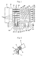
- Figs. 1 through 6 show a first embodiment of the present invention.
- a wire harness W/H composed of a plurality of shielded wires 10 and an electric wire 20 other than the shielded wire 10 is wired in an engine room of a car.
- An end of the wire harness W/H is connected to one connector 30 connected to a fuel injection control apparatus 31 by fitting the connector 30 in the fuel injection control apparatus 31.
- the shielded wire 10 is composed of one or a plurality of core wires 12 consisting of insulated coated electric wires which constitute one or a plurality of signal wires and one drain wire 11.
- the drain wire 11 and the core wires 12 are coated with a shielding layer 13 consisting of a metal foil or a tube of a braided metal and a sheath 14 made of an insulating resin material, with the shielding layer 13 coated with the sheath 14.
- the drain wire 11 is brought into contact with the shielding layer 13 to make the shielding layer 13 and drain wire 11 electrically conductive.
- the sheath 14 and the shielding layer 13 of the shielded wire 10 are cut to peel a part of the sheath 14 and the shielding layer 13 in a length of about 40mm from a front end of the shielded wire 10 to lead out the drain wire 11 and the core wire 12 from the front end of the shielded wire 10.
- the wire harness W/H has seven shielded wires 10.
- These shielded wires include a shielded wire 10A connected with a knock sensor, a shielded wire 10B connected with an engine revolution sensor, shielded wires 10C, 10D connected with left and right air-fuel ratio sensors respectively, shielded wires 10E, 10F connected with left and right oxygen sensors respectively, and a shielded wire 10G connected with a throttle sensor.
- the shielding layer 13 of each of the shielded wires 10A, 10B consists of the tube of the braided metal, whereas the shielding layer 13 of each of the remaining shielded wires 10C through 10G consists of the metal foil.
- the electric wire 20 other than the shielded wire 10 of the wire harness W/H is not shown.
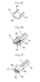
- the intermediate crimping terminal 40 a pair of crimping barrels 40b is provided at both sides of a substrate portion 40a consisting of a conductive metal plate.
- the intermediate crimping terminal 40 is U-shaped in section.
- Ends of the drain wires 11 parallel with one another and exposed ends of core wires 50a of the ground wire 50 are disposed on the substrate portion 40a.
- the crimping barrels 40b are caulked inward to bring the substrate portion 40a and the crimping barrels 40b into close contact with the drain wires 11 and the ground wire 50 to collectively connect the drain wires 11 and the ground wire 50 with each other by the crimping connection.
- a connected portion at which the drain wires 11 and the ground wire 50 is connected with each other by means of the intermediate crimping terminal 40 by the crimping connection is covered with a bottomed cylindrical cap 41 made of insulating resin.
- the three drain wires 11A, 11C, and 11D and a ground wire 50A are connected with each other by means of an intermediate crimping terminal 40A by the crimping connection, and the three drain wires 11B, 11E, and 11F and a ground wire 50B are connected with each other by means of an intermediate crimping terminal 40B by the crimping connection.
- a ground wire 50C connected with the connector 30 is connected with a ground terminal 51A connected with the ground wire 50A to use the ground wire 50C for grounding a circuit of the fuel injection control apparatus 31.
- a ground wire 50D for grounding a circuit inside the cabin is connected with a ground terminal 51B connected with the ground wire 50B.
- a drain wire 11G of the remaining shielded wire 10G is inserted through a waterproof shrinkable tube 42 and connected with the connector 30.
- a water-stop rubber stopper 52 is mounted on a connected portion at which the ground wire 50 and the ground terminal 51 are connected with each other, a connected portion at which the connector 30 and the core electric wire 12 of the shielded wire 10 are connected with each other, a connected portion at which the connector 30 and the drain wire 11G are connected with each other, and a connected portion at which the connector 30 and the electric wire 20 other than the shielded wire 10 are connected with each other to form a water-stop portion so that the connector 30 is waterproofed.
- silicone may be dripped to a water-stop portion to form the water-stop portion.
- a connector cover 32 is mounted on a wire harness-connected surface of the connector 30 to cover the connected portion at which the connector 30 and the wire harness W/H are connected with each other.
- the diameter of the connector cover 32 becomes smaller from its one end where the connector 30 is mounted to its other side.
- a flange 32a for locking use is provided sideways by projecting it from both peripheral edges of the connector cover 32 at the one end thereof having the largest diameter. The flange 32a is locked to a concave portion 30a formed on the connector 30 to mount the connector cover 32 on the connector 30.
- the other end of the connector cover 32 having the smallest diameter is formed as an opening 32b.
- the wire harness W/H lead out straight to the outside from the opening 32b is fixed to a tape-winding tongue piece 32c formed at the peripheral edge of the opening 32b by winding a tape T round the tape-winding tongue piece 32c.
- the connected portion at which the drain wire 11 of the shielded wire 10 and the ground wire 50 are connected with each other is accommodated in the connector cover 32.
- a slit 32d is formed on the connector cover 32 from the one end thereof to the other end thereof.
- the sheath 14 and the shielding layer 13 are also cut to peel a part of the sheath 14 and the shielding layer 13 to lead out the core electric wire 12 from the shielding layer 13, and a waterproof connector 34 is connected with the end of the lead out core electric wire 12 of each shielded wire 10.
- the waterproof connector 34 has a waterproof function for the core electric wire 12 because the waterproof connector 34 has a water-stop rubber stopper 34a.
- Each waterproof connector 34 is connected with a sensor.
- the ground wire 50 is not connected with the waterproof connector 34. Thereby water which has penetrated from one end of the shielded wire 10 into the other end thereof is drained to the other end thereof.
- the entire wire harness W/H prevents water from penetrating into sensors (or electric circuit) from the outside of the waterproof connector 34 and the core electric wire 12.
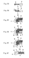
- the shielded wire-grounding method is described below. Initially at a first step, as shown in Fig. 6(A) , the sheath 14 and the shielding layer 13 are cut to peel the sheath 14 and the shielding layer 13 in a length spaced by about 40mm from the front end of the shielded wire 10 to lead out the drain wire 11 and the core electric wires 12 in a length of about 40mm. At a second step, as shown in Fig. 6(B) , a crimping terminal is connected to ends of the core electric wires 12 and the electric wire 20 other than the shielded wire 10 respectively by the crimping connection. In Fig. 6(B) , only the shielded wire 10 is shown.
- the crimping terminals connected to the ends of the core electric wires 12 and the electric wire 20 other than the shielded wire 10 are inserted into the cavities of the connector 30 to lock the crimping terminal thereto.
- the drain wires 11 and the ground wire 50 are connected with each other by the crimping connection by means of the intermediate crimping terminal 40.
- the cap 41 is mounted on the connected portion at which the drain wires 11 and the ground wire 50 are connected with each other.
- the last step namely, at a sixth step, as shown in Fig.
- the connector cover 32 is mounted on the connector 30 to cover the connected portion at which the connector 30 and the wire harness W/H are connected with each other by means of the connector cover 32, and the connected portion at which the drain wires 11 and the ground wire 50 are connected with each other is accommodated inside the connector cover 32.
- the drain wire 11 of the shielded wire 10 and the ground wire 50 are connected with each other by means of the intermediate crimping terminal 40 by the crimping connection. Therefore the method of the present invention is capable of decreasing the lead-out length of the drain wire 11 to 40mm at the shortest, as compared with the case in which the drain wires 11 and the ground wire 50 are connected with each other by welding the portion of the drain wire 11 to be connected and the portion of the ground wire 50 to be connected to each other. Because it is possible to decrease the peeling length of the shielded wire 10 by the above-described length, the performance of shielding the shielded wire 10 can be enhanced.
- the connected portion at which the drain wire 11 and the ground wire 50 are connected with each other is little influenced by external vibration and heat.
- the connected portion at which the drain wire 11 and the ground wire 50 are connected with each other is little influenced by external vibration and heat.
- the operation order of the first step through the sixth step is not limited to the above-described order.
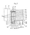
- Fig. 7 shows a first modification of the first embodiment.
- the drain wire 11G of the shielded wire 10G is not connected with the connector 30, but is connected with the ground wire 50A together with the other drain wires 11A, 11C, and 11D by means of the intermediate crimping terminal 40A by the crimping connection.
- the drain wires 11 of all the shielded wires 10 are not connected with the connector, but grounded to the car body panel through the ground wire 50.
- Fig. 8 shows a second modification of the first embodiment.
- a slit 15 is formed through a portion, of the shielding layer 13 and the sheath 14, which is disposed at an intermediate position of the shielded wire 10F, and the drain wire 11F is lead out from the slit 15 to connect the drain wire 11F to the ground wire 50B together with the drain wires 11B, 11E of the other shielded wires 10B and 10E by means of an intermediate crimping terminal 40B.
- the drain wire 11 may be lead out from an intermediate position of the other shielded wires 10A through 10E and 10G.
- Fig. 9 shows a third modification of the first embodiment.
- the configuration of the connector cover to be mounted on the connector is different from that of the connector cover of the first embodiment.
- An opening 32a' of a connector cover 32' from which the wire harness is lead out is formed on a peripheral wall thereof orthogonal to a mounting surface 32b' to be mounted on the connector 30.
- the wire harness W/H connected with the connector is lead out sideways from the opening 32a'.
- a locking claw 32c' is formed at a necessary position of the mounting surface 32b' of the connector cover 32'. The locking claw 32c' is locked to the connector 30 to mount the connector cover 32' on the connector 30.
- Fig. 10 shows a fourth modification of the first embodiment.
- the connector cover is not mounted on the connector 30.
- a cylindrical corrugate tube 33 having mountains and valleys axially alternately formed is externally mounted on the shielded wire 10 and the electric wire 20 other than the shielded wire 10.
- the corrugate tube 33 accommodates the connected portion at which the drain wire 11 of the shielded wires 10 and the ground wire 50 are connected with each other by the crimping connection.
- the corrugate tube 33 accommodates the connected portion at which the drain wire 11 and the ground wire 50 are connected with each other by the crimping connection. Therefore without winding a tape round the wire harness W/H, it is possible to dispose the connected portion at which the drain wire 11 and the ground wire 50 are connected with each other along the wire harness W/H.
- Other constructions and operations and effects of the fourth modification are similar to those of the first embodiment. Thus the same parts of the fourth modification as those of the first embodiment are denoted by the same reference numerals as those of the first embodiment, and description thereof is omitted herein.
- Figs. 11 and 12 show a second embodiment.
- the method of connecting the drain wire 11 and the ground wire 50 with each other is different from that of the first embodiment.
- the drain wire 11 and the ground wire 50 are connected with each other by twisting strands of the drain wire 11 and those of the ground wire 50. More specifically, as shown in Fig. 12 , the strands of the drain wire 11 and those of the ground wire 50 are untwisted, bundled, and twisted to form a connected portion 43.
- the heat-shrinkable tube 44 is heated to shrink it so that the heat-shrinkable tube 44 adheres to a peripheral surface of the connected portion 43.
- the heat-shrinkable tube 44 is a waterproof shrinkable tube containing a thermoplastic adhesive agent in its inner wall. By thermally shrinking the heat-shrinkable tube 44, the adhesive agent fuses, thus adhering to the outer side of the twisted drain wire and the ground wire.
- Fig. 13 shows a modification of the second embodiment.
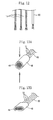
- the metal tube 45 is caulked in a direction from both sides thereof to crimp the metal tube 45 to the connected portion 43, as shown in Fig. 13(B) .
- the metal tube 45 is crimped to the connected portion 43 formed by twisting the strands of the drain wire 11 and those of the ground wire 50. Therefore the strands of the drain wire 11 and those of the ground wire 50 are prevented from being untwisted. Further the strands of the drain wire 11 and those of the ground wire 50 are electrically conductive even though the connected portion 43 is covered with the metal tube 45. Thus it is possible to secure a high electrical connection between the strands of the drain wire 11 and those of the ground wire 50.
- the metal tube 45 crimped to the connected portion 43 at which the drain wire 11 and the ground wire 50 are connected with each other may be covered with a cap similar to that of the first embodiment.
- Figs. 14 and 15 show a third embodiment.
- the construction of the ground wire to be connected with the drain wire 11 is different from that of the above-described embodiments. More specifically, as shown in Fig. 15 , a ground wire 53 consists of a single core wire having a conductor covered with an insulating coating 54.
- a connector accommodation terminal 56 accommodated inside the connector 30 is connected to a conductor 55a exposed at one end of the ground wire 53 by peeling the insulating coating 54, whereas a conductor 55b disposed at the other end of the ground wire 53 is connected to the drain wires 11A, 11C, and 11D by means of the intermediate crimping terminal 40A.
- the sectional area of the conductor 55 of the ground wire 53 is set to 0.5mm 2 , 0.75mm 2 or 1.25mm 2 .
- the core electric wire 12 is connected to the connector 30 connected with the connector accommodation terminal 56 connected with the ground wire 53.
- a water-stop portion consisting of a water-stop rubber stopper 57 is provided at the connected portion at which the ground wire 53 and the connector accommodation terminal 56 are connected with each other, and the peripheral surface of the water-stop rubber stopper 57 is brought into close contact with the inner peripheral surface of a cavity 30b of the connector 30 to prevent water from penetrating into the connector 30.
- a circuit member consisting of a printed-circuit board 35 is accommodated inside an electronic control unit composed of the fuel injection control apparatus 31 to which the connector 30 is connected.
- the connector accommodation terminal 56 connected with the ground wire 53 accommodated inside the connector 30 is connected with a terminal member 37 connected with a conductor 36 constructing a ground circuit of the printed-circuit board 35.
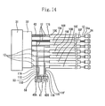
- the connected portion at which the drain wires 11A, 11C, and 11D and the ground wire 53 are connected with each other is connected with the connected portion at which the drain wires 11B, 11E, and 11F are connected with each other through a ground wire 58 for relay connection use.
- the ground wire 58 for relay connection use consists of a single core wire whose conductor is covered with an insulating coating 59.
- a conductor 70a exposed at one end of the ground wire 53 by peeling the insulating coating 59 is connected to the drain wires 11A, 11C, and 11D and the ground wire 53 by means of the intermediate crimping terminal 40A by the crimping connection.
- a conductor 70b disposed at the other end of the ground wire 58 is connected with the drain wires 11B, 11E, and 11F by means of an intermediate crimping terminal 40B by the crimping connection.
- the connector accommodation terminal 56 connected with the ground wire 53 is connected with the ground circuit of the printed-circuit board 35 accommodated in the electronic control unit.
- the ground connection can be easily accomplished. Further it is unnecessary to wire the ground wire 53 to the car body panel and thus possible to decrease the length thereof. Thus it is possible to simplify the shielded wire-grounding construction.
- the ground wire 53 consists of the single core wire whose conductor is covered with the insulating coating 54, no gap is formed between the conductor 55 and the insulating coating 54.
- the drain wire 11 and the ground wire 50 may be connected with each other by twisting the strands thereof.
- Other constructions, operations, and effects of the third embodiment are similar to those of the first embodiment. Thus the same parts of the third embodiment as those of the first embodiment are denoted by the same reference numerals as those of the first embodiment, and description thereof is omitted herein.
- Figs. 16 and 17 show a fourth embodiment of the present invention.
- the drain wire 11 of the shielded wire 10 and the ground wire 50 are connected with each other through a joint bus bar 61 disposed inside a joint connector 60.
- crimping terminals 62, 63 are connected to a lead-out side end of each drain wire 11 lead out from the shielded wire 10 and to conductors disposed at other end of the ground wire 50 disposed at a side opposite to one end thereof connected with a ground terminal.
- the crimping terminals 62, 63 have female terminals 62a, 63a respectively connected with the joint bus bar 61 at one end thereof and crimping barrels 62b, 63b at the other end thereof.
- the crimping barrels 62b and 63b are caulked to the drain wires 11 and the ground wire 50 to connect the drain wires 11 and the ground wire 50 with each other by the crimping connection.
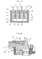
- the joint bus bar 61 connecting the drain wires 11 and the ground wire 50 to each other has a belt-shaped joint portion 61a and a plurality of male tab-shaped terminal portions 61b projected from the joint portion 61a.
- the joint bus bar 61 is accommodated inside the joint connector 60 made of resin molding.
- the terminal portions 61b of the joint bus bar 61 are disposed respectively in the cavities 60a of the joint connector 60.
- the crimping terminals 62 of the drain wires 11 and the crimping terminal 63 of the ground wire 50 are inserted into the cavities 60a and locked thereto to connect the female terminal portions 62a, 63a of the female crimping terminals 62, 63 to the terminal portions 61b of the joint bus bar 61 respectively. Thereby the drain wires 11 and the ground wire 50 are connected with each other through the joint bus bar 61.
- the joint connector 60 is fixed to an inner wall of a connector cover 32', similar to that of the second embodiment, mounted on the connector 30 to which the core electric wire 12 of the shielded wire 10 is connected.
- the drain wires 11 connected with the joint connector 60 and the ground wire 50 connected therewith are lead out through an opening 32a' of the connector cover 32'.
- the shielded wire-grounding method is described below. Initially at a first step, the sheath 14 and the shielding layer 13 are cut to peel them in a length spaced by about 40mm from the front end of the shielded wire 10 to lead out the drain wire 11 and the core electric wires 12 in a length of about 40mm. At a second step, crimping terminals 62, 63 are connected to ends of the drain wire 11, the core electric wires 12, the ground wire 50, and the electric wire 20 other than the shielded wire 10 respectively by crimping connection. At a third step, the crimping terminals connected to the ends of the core electric wires 12 and the electric wire 20 other than the shielded wire 10 are inserted into the cavities of the connector 30 and locked thereto.
- the crimping terminals 62 of the drain wires 11 and the crimping terminal 63 of the ground wire 50 are inserted into the cavities 60a of the joint connector 60 and locked thereto to connect the drain wires 11 and the ground wire 50 to each other through the joint bus bar 61.
- the joint connector 60 is fixed to the inner wall of the connector cover 32' mounted on the connector 30.
- the connector cover 32' is mounted on the connector 30 to cover the connected portion at which the connector 30 and the wire harness W/H are connected with each other by means of the connector cover 32, and the joint connector 60 is accommodated inside the connector cover 32.
- the operation of the fourth step and that of the fifth step may be performed in a reverse order.
- the method of the present invention is capable of decreasing the lead-out length of the drain wire 11 to 40mm at the shortest, as compared with the case in which the portion of the drain wire 11 to be connected and the portion of the ground wire 50 to be connected are connected with each other by welding the portions thereof to each other. Because it is possible to decrease the peeling length of the shielded wire 10 by the above-described length, it is possible to enhance the performance of shielding the shielded wire 10.
- the joint connector 60 connecting the drain wires 11 and the ground wire 50 to each other is accommodated in the connector cover 32 by fixing the joint connector 60 to the inner wall of the connector cover 32' mounted on the connector 30 connected with the end of the wire harness W/H, the joint connector 60 is little influenced by external vibration and heat. Thus it is possible to enhance the performance of protecting the joint connector 60. Thereby it is unnecessary to fix the joint connector to the wire harness W/H by winding a tape round the wire harness W/H. Therefore it is possible to restrain the wire harness W/H from becoming locally large and thus make the wire harness W/H slim and enhance the operability.
- the terminal to be connected to the drain wires 11 and the ground wire 50 is not limited to the crimping terminal, but a pressure-welded terminal having a pressure welding slot may be used.
- the ground wire may consist of the single core wire with which the connector accommodation terminal is connected to one end thereof.
- Fig. 18 shows a modification of the fourth embodiment.
- the joint connector 60 is not fixed to the inner wall of the connector cover 32' through an adhesive agent, but a connector accommodation portion 32e' for accommodating the joint connector 60 therein is formed integrally with the inner wall of the connector cover 32'.
- a locking groove 32f' is formed on the inner surface of the connector accommodation portion 32 e', and a locking claw 60b is formed on an outer surface of the joint connector 60.
Landscapes
- Insulated Conductors (AREA)
- Connections Effected By Soldering, Adhesion, Or Permanent Deformation (AREA)
- Cable Accessories (AREA)
- Manufacturing Of Electrical Connectors (AREA)
Applications Claiming Priority (4)
| Application Number | Priority Date | Filing Date | Title |
|---|---|---|---|
| JP2006221683 | 2006-08-15 | ||
| JP2006260569 | 2006-09-26 | ||
| JP2007179348A JP2008108699A (ja) | 2006-08-15 | 2007-07-09 | シールド線のアース処理構造およびアース処理方法 |
| PCT/JP2007/064424 WO2008020527A1 (fr) | 2006-08-15 | 2007-07-23 | Structure de mise à la masse et procédé de mise à la masse pour câble blindé |
Publications (2)
| Publication Number | Publication Date |
|---|---|
| EP2053694A1 true EP2053694A1 (de) | 2009-04-29 |
| EP2053694A4 EP2053694A4 (de) | 2011-09-07 |
Family
ID=39082054
Family Applications (1)
| Application Number | Title | Priority Date | Filing Date |
|---|---|---|---|
| EP07791157A Withdrawn EP2053694A4 (de) | 2006-08-15 | 2007-07-23 | Masseverbindungsstruktur und masseverbindungsverfahren für abschirmleitung |
Country Status (5)
| Country | Link |
|---|---|
| US (2) | US20090314511A1 (de) |
| EP (1) | EP2053694A4 (de) |
| JP (1) | JP2008108699A (de) |
| CN (1) | CN101507051B (de) |
| WO (1) | WO2008020527A1 (de) |
Cited By (1)
| Publication number | Priority date | Publication date | Assignee | Title |
|---|---|---|---|---|
| EP3291375B1 (de) * | 2016-09-01 | 2019-04-10 | Nexans | Verfahren zum elektrisch leitenden verbinden von elektrischen leitern |
Families Citing this family (49)
| Publication number | Priority date | Publication date | Assignee | Title |
|---|---|---|---|---|
| JP5188713B2 (ja) * | 2006-02-02 | 2013-04-24 | 株式会社オートネットワーク技術研究所 | ドレン線止水構造を備えたシールド線およびドレン線止水方法 |
| JP5144319B2 (ja) * | 2008-03-14 | 2013-02-13 | 古河電気工業株式会社 | シールド電線におけるドレーン線とアース線とのジョイント部の止水構造及び止水方法 |
| JP5304620B2 (ja) * | 2009-12-01 | 2013-10-02 | 株式会社デンソー | 電子制御システム |
| JP5566715B2 (ja) | 2010-02-05 | 2014-08-06 | 矢崎総業株式会社 | 加締め接続構造 |
| WO2011101890A1 (ja) * | 2010-02-17 | 2011-08-25 | 株式会社オートネットワーク技術研究所 | 短絡回路を含むワイヤハーネス及びその製造方法 |
| JP2011222311A (ja) * | 2010-04-09 | 2011-11-04 | Yazaki Corp | 電線接続方法及びワイヤハーネス |
| JP5768380B2 (ja) * | 2011-01-19 | 2015-08-26 | 住友電装株式会社 | ワイヤハーネス用のプロテクタ |
| JP5762219B2 (ja) * | 2011-08-31 | 2015-08-12 | 矢崎総業株式会社 | シールド電線の編組シールド層とドレイン線との接続方法、及び、接続構造 |
| JP5742602B2 (ja) * | 2011-09-05 | 2015-07-01 | 株式会社オートネットワーク技術研究所 | シールド用ジョイントコネクタ |
| JP5781410B2 (ja) * | 2011-09-26 | 2015-09-24 | 矢崎総業株式会社 | 単芯線電線と撚線電線との接続方法 |
| JP6002985B2 (ja) * | 2011-12-27 | 2016-10-05 | 矢崎総業株式会社 | ワイヤハーネス用中間部材及びワイヤハーネス |
| EP2806501A4 (de) * | 2012-01-20 | 2015-09-30 | Yazaki Corp | Erdverbindungsstruktur und herstellungsverfahren dafür |
| JP5954869B2 (ja) * | 2012-08-30 | 2016-07-20 | 富士重工業株式会社 | ワイヤーハーネス |
| US9966165B2 (en) | 2012-12-31 | 2018-05-08 | Fci Americas Technology Llc | Electrical cable assembly |
| US9741465B2 (en) | 2012-12-31 | 2017-08-22 | Fci Americas Technology Llc | Electrical cable assembly |
| US8905767B2 (en) * | 2013-02-07 | 2014-12-09 | Tyco Electronics Corporation | Cable assembly and connector module having a drain wire and a ground ferrule that are laser-welded together |
| US9673537B2 (en) * | 2013-03-15 | 2017-06-06 | Thomas & Betts International, Llc | Wire compression connector |
| FR3003389B1 (fr) * | 2013-03-15 | 2018-03-30 | Thales | Procede de reprise des blindages des cables d un toron sur un connecteur electrique et ensemble de connexion d un toron |
| JP6044509B2 (ja) * | 2013-11-01 | 2016-12-14 | 住友電装株式会社 | ワイヤハーネスの止水構造 |
| US9440598B2 (en) * | 2013-11-11 | 2016-09-13 | Aees, Inc. | Wiring harness assembly for vehicle including source splice overlay |
| JP5763736B2 (ja) * | 2013-12-02 | 2015-08-12 | 本田技研工業株式会社 | 接続器の防液構造 |
| WO2015098639A1 (ja) * | 2013-12-26 | 2015-07-02 | 古河電気工業株式会社 | 多層絶縁電線、コイルおよび電気・電子機器 |
| CN104078816B (zh) * | 2014-05-13 | 2017-01-11 | 国家电网公司 | 一种接地线操作杆万能转换装置 |
| CN106463936A (zh) * | 2014-06-06 | 2017-02-22 | 矢崎总业株式会社 | 线束布设结构 |
| WO2016048374A1 (en) | 2014-09-26 | 2016-03-31 | Hewlett Packard Enterprise Development Lp | Receptacle for connecting a multi-lane or one-lane cable |
| DE102014223119B4 (de) * | 2014-11-12 | 2021-01-28 | Leoni Kabel Gmbh | Datenkabel sowie Verfahren zur Herstellung eines Datenkabels |
| JP6210971B2 (ja) * | 2014-12-26 | 2017-10-11 | 矢崎総業株式会社 | 止水構造及びワイヤハーネス |
| WO2016133499A1 (en) | 2015-02-18 | 2016-08-25 | Hewlett Packard Enterprise Development Lp | Pull-tabs for disengaging a cable assembly from a receptacle |
| US10741963B2 (en) * | 2015-02-27 | 2020-08-11 | Hewlett Packard Enterprise Development Lp | Cable assembly with conjoined one-lane cable assemblies |
| US10389068B2 (en) | 2015-04-29 | 2019-08-20 | Hewlett Packard Enterprise Development Lp | Multiple cable housing assembly |
| CN104952518B (zh) * | 2015-05-26 | 2017-07-11 | 奇瑞汽车股份有限公司 | 屏蔽线 |
| WO2016191662A1 (en) | 2015-05-27 | 2016-12-01 | Intelligent Technologies International, Inc. | Vehicle wire harness |
| JP6132216B2 (ja) * | 2015-07-03 | 2017-05-24 | 住友電装株式会社 | ワイヤーハーネス |
| JP6202055B2 (ja) * | 2015-07-17 | 2017-09-27 | 住友電装株式会社 | シールド線のドレン線止水構造 |
| CN105222261B (zh) * | 2015-10-15 | 2017-12-05 | 珠海格力电器股份有限公司 | 一种雾化片结构及加湿器 |
| DE102016221412B4 (de) * | 2015-11-04 | 2024-03-21 | Gentherm Inc. | Quetschverbindung für geflechtartiges Abschirmmaterial zur Verwendung in mit kapazitiven Sensoren ausgestatteten Lenkrädern |
| US10056702B2 (en) | 2015-11-04 | 2018-08-21 | Gentherm, Inc. | Crimp connection for mesh shielding material used in steering wheel with capacitive sensing |
| JP6673071B2 (ja) * | 2016-07-19 | 2020-03-25 | 株式会社オートネットワーク技術研究所 | シールド部材、シールド部材付電線、シールド部材の中間製造物及びシールド部材の製造方法 |
| US11196186B2 (en) | 2016-11-28 | 2021-12-07 | Ppc Broadband, Inc. | Coaxial cable bonding/grounding blocks |
| CA2987136A1 (en) * | 2016-11-28 | 2018-05-28 | Ppc Broadband, Inc. | Coaxial cable bonding/ground blocks having an integrated ground wire |
| US10686263B2 (en) | 2016-11-28 | 2020-06-16 | Ppc Broadband, Inc. | Coaxial cable bonding/grounding blocks having an integrated ground wire |
| US9979167B1 (en) * | 2017-08-28 | 2018-05-22 | Delphi Technologies, Inc. | Device and method for splicing shielded wire cables |
| CN109510161B (zh) * | 2018-11-29 | 2023-08-25 | 西安神电高压电器有限公司 | 一种全绝缘管型母线系统 |
| CN113271837B (zh) * | 2019-02-19 | 2024-09-27 | 奥林巴斯株式会社 | 内窥镜前端构造及内窥镜 |
| JP7140725B2 (ja) | 2019-07-31 | 2022-09-21 | 本田技研工業株式会社 | 電源装置 |
| JP7371505B2 (ja) * | 2020-01-20 | 2023-10-31 | 住友電装株式会社 | ワイヤハーネス |
| JP7404945B2 (ja) * | 2020-03-11 | 2023-12-26 | 住友電装株式会社 | 電流分岐装置 |
| KR102814047B1 (ko) * | 2020-11-17 | 2025-05-29 | 현대자동차주식회사 | 배선 커넥터 조립체 |
| DE102021103797B3 (de) * | 2021-02-18 | 2022-05-19 | HARTING Automotive GmbH | Ladebuchse für einen elektrischen energiespeicher |
Family Cites Families (25)
| Publication number | Priority date | Publication date | Assignee | Title |
|---|---|---|---|---|
| US2678963A (en) * | 1951-06-27 | 1954-05-18 | Collins Radio Co | Through-clamp for coaxial cables |
| US2806215A (en) * | 1953-11-04 | 1957-09-10 | Aircraft Marine Prod Inc | Aluminum ferrule-copper tongue terminal and method of making |
| US3517375A (en) * | 1968-01-29 | 1970-06-23 | Berg Electronics Inc | Crimping terminal for coaxial cable |
| US3533055A (en) * | 1968-03-14 | 1970-10-06 | Alfred M Zak | Electrical connector and method and apparatus for making same |
| US5315066A (en) * | 1982-05-03 | 1994-05-24 | Betts Industries, Inc. | Sealed wire connector |
| NL8500885A (nl) * | 1985-03-26 | 1986-10-16 | Du Pont Nederland | Werkwijze voor het bewerken van een kabeleinde en hierbij toegepaste kabelconnector. |
| JPH01107877A (ja) | 1987-10-20 | 1989-04-25 | Iseki & Co Ltd | 回転選別筒の清掃装置 |
| JPH067447B2 (ja) * | 1987-12-08 | 1994-01-26 | 矢崎総業株式会社 | ワイヤーハーネス |
| JPH01107877U (de) * | 1988-01-12 | 1989-07-20 | ||
| US5267878A (en) * | 1990-03-05 | 1993-12-07 | Yazaki Corporation | Electrical connector for shielding cable |
| JPH04237979A (ja) * | 1991-01-22 | 1992-08-26 | Fujikura Ltd | シールドケーブルの端末構造 |
| JPH0550663U (ja) * | 1991-12-06 | 1993-07-02 | 株式会社ニチフ端子工業 | 電線接続端子 |
| JPH0796314B2 (ja) | 1992-01-31 | 1995-10-18 | キヤノン株式会社 | 印刷装置 |
| JP2772319B2 (ja) * | 1992-07-13 | 1998-07-02 | 矢崎総業株式会社 | コネクタのシール構造 |
| JP2529634B2 (ja) | 1992-09-07 | 1996-08-28 | 本州製紙株式会社 | 段ボ―ル用接着剤の製造方法 |
| JP2588006Y2 (ja) * | 1993-06-04 | 1999-01-06 | トーマス アンド ベッツ コーポレーション | シールド線端末処理用端子 |
| JPH08339863A (ja) * | 1995-06-09 | 1996-12-24 | Yamaha Corp | コネクタの接続構造 |
| JP2000068007A (ja) * | 1998-08-20 | 2000-03-03 | Fujitsu Takamisawa Component Ltd | ケーブル付き平衡伝送用コネクタ |
| JP2000268893A (ja) * | 1999-03-15 | 2000-09-29 | Sumitomo Wiring Syst Ltd | 複数のシールド線のアース接続構造 |
| JP3517155B2 (ja) * | 1999-05-07 | 2004-04-05 | 矢崎総業株式会社 | シールド電線の接続構造及びシールド端子接続方法 |
| JP2001135419A (ja) * | 1999-11-09 | 2001-05-18 | Auto Network Gijutsu Kenkyusho:Kk | シールドケーブルの端末処理方法及び端末処理構造 |
| DE10218398B4 (de) * | 2001-04-25 | 2006-08-17 | Yazaki Corp. | Verfahren zur Herstellung einer Abzweigverbindung an einem abgeschirmten Leiter |
| JP4070623B2 (ja) * | 2003-01-30 | 2008-04-02 | 株式会社オートネットワーク技術研究所 | シールドケーブル |
| JP2005093198A (ja) * | 2003-09-17 | 2005-04-07 | Auto Network Gijutsu Kenkyusho:Kk | シールド電線のアース処理構造 |
| DE102006013490A1 (de) * | 2005-03-23 | 2006-10-05 | Yazaki Corp. | Struktur zur Koaxialkabelenden-Verarbeitung, Koaxialkabel-Abschirmungsklemme und Press-Befestigungsvorrichtung |
-
2007
- 2007-07-09 JP JP2007179348A patent/JP2008108699A/ja active Pending
- 2007-07-23 EP EP07791157A patent/EP2053694A4/de not_active Withdrawn
- 2007-07-23 WO PCT/JP2007/064424 patent/WO2008020527A1/ja not_active Ceased
- 2007-07-23 CN CN2007800303638A patent/CN101507051B/zh not_active Expired - Fee Related
- 2007-07-23 US US12/309,232 patent/US20090314511A1/en not_active Abandoned
-
2011
- 2011-03-23 US US13/064,418 patent/US8258402B2/en not_active Expired - Fee Related
Cited By (1)
| Publication number | Priority date | Publication date | Assignee | Title |
|---|---|---|---|---|
| EP3291375B1 (de) * | 2016-09-01 | 2019-04-10 | Nexans | Verfahren zum elektrisch leitenden verbinden von elektrischen leitern |
Also Published As
| Publication number | Publication date |
|---|---|
| CN101507051B (zh) | 2012-08-01 |
| WO2008020527A1 (fr) | 2008-02-21 |
| CN101507051A (zh) | 2009-08-12 |
| JP2008108699A (ja) | 2008-05-08 |
| US8258402B2 (en) | 2012-09-04 |
| US20090314511A1 (en) | 2009-12-24 |
| EP2053694A4 (de) | 2011-09-07 |
| US20110168423A1 (en) | 2011-07-14 |
Similar Documents
| Publication | Publication Date | Title |
|---|---|---|
| US8258402B2 (en) | Shielded wire-grounding construction | |
| US6781059B2 (en) | Shielded wire | |
| EP1037327B1 (de) | Erdungskonstruktion für eine Vielzahl von abgeschirmten Kabeln und Verfahren zur Herstellung einer Erdungskonstruktion | |
| EP2306601B1 (de) | Verbinder | |
| JP6527895B2 (ja) | 導電路同士接続部の構造、及びワイヤハーネス | |
| EP2841309B1 (de) | Kabelbaum | |
| EP2876651B1 (de) | Kabelbaum | |
| US9263865B2 (en) | Water stop structure for wire harness and wire harness | |
| US20130126232A1 (en) | Wire harness waterproof structure | |
| CN100386919C (zh) | 异种电线间的连接构造 | |
| US5132489A (en) | Shielded electric cable | |
| KR102008527B1 (ko) | 차폐 케이블 어셈블리 및 이를 구비하는 커넥터 하우징 어셈블리 | |
| US6616463B1 (en) | Method and apparatus for solder splicing and grounding coaxial cables | |
| JP2005093198A (ja) | シールド電線のアース処理構造 | |
| JP4767137B2 (ja) | シールド線の止水方法および止水構造 | |
| JP5096950B2 (ja) | 端末ジョイント部の保護キャップ | |
| US7803000B2 (en) | Wire connection unit | |
| JP2007207738A (ja) | シールドワイヤハーネスおよびシールドワイヤハーネスの製造方法 | |
| JP2007184172A (ja) | シールド線のアース接続構造 | |
| JPH0773948A (ja) | シールド電線のアース方法と、それに用いるアース用接続子 | |
| JP2002359017A (ja) | 電線接続構造および機器ケース体内の空気抜き方法 | |
| JPH08340615A (ja) | シールド線のアース接続構造 | |
| JPH1050411A (ja) | シールド処理部 | |
| JP2000184556A (ja) | 自動車のエンジンルーム内へのワイヤハーネス接続構造 | |
| JP4070623B2 (ja) | シールドケーブル |
Legal Events
| Date | Code | Title | Description |
|---|---|---|---|
| PUAI | Public reference made under article 153(3) epc to a published international application that has entered the european phase |
Free format text: ORIGINAL CODE: 0009012 |
|
| 17P | Request for examination filed |
Effective date: 20090202 |
|
| AK | Designated contracting states |
Kind code of ref document: A1 Designated state(s): AT BE BG CH CY CZ DE DK EE ES FI FR GB GR HU IE IS IT LI LT LU LV MC MT NL PL PT RO SE SI SK TR |
|
| AX | Request for extension of the european patent |
Extension state: AL BA HR MK RS |
|
| DAX | Request for extension of the european patent (deleted) | ||
| RBV | Designated contracting states (corrected) |
Designated state(s): DE FR |
|
| A4 | Supplementary search report drawn up and despatched |
Effective date: 20110804 |
|
| RIC1 | Information provided on ipc code assigned before grant |
Ipc: H01R 13/52 20060101ALI20110729BHEP Ipc: H01R 4/72 20060101ALI20110729BHEP Ipc: H01R 9/03 20060101ALI20110729BHEP Ipc: H01R 4/22 20060101ALI20110729BHEP Ipc: H01R 4/18 20060101AFI20110729BHEP |
|
| GRAP | Despatch of communication of intention to grant a patent |
Free format text: ORIGINAL CODE: EPIDOSNIGR1 |
|
| RIC1 | Information provided on ipc code assigned before grant |
Ipc: H01R 4/72 20060101ALI20140606BHEP Ipc: H01R 13/52 20060101ALI20140606BHEP Ipc: H01R 9/03 20060101ALI20140606BHEP Ipc: H01R 4/18 20060101AFI20140606BHEP Ipc: H01R 105/00 20060101ALI20140606BHEP Ipc: H01R 4/22 20060101ALI20140606BHEP Ipc: H01R 24/56 20110101ALI20140606BHEP Ipc: H01R 9/05 20060101ALI20140606BHEP |
|
| INTG | Intention to grant announced |
Effective date: 20140715 |
|
| STAA | Information on the status of an ep patent application or granted ep patent |
Free format text: STATUS: THE APPLICATION IS DEEMED TO BE WITHDRAWN |
|
| 18D | Application deemed to be withdrawn |
Effective date: 20141126 |