EP2056068B1 - Capteur de force d'inertie - Google Patents
Capteur de force d'inertie Download PDFInfo
- Publication number
- EP2056068B1 EP2056068B1 EP07792698A EP07792698A EP2056068B1 EP 2056068 B1 EP2056068 B1 EP 2056068B1 EP 07792698 A EP07792698 A EP 07792698A EP 07792698 A EP07792698 A EP 07792698A EP 2056068 B1 EP2056068 B1 EP 2056068B1
- Authority
- EP
- European Patent Office
- Prior art keywords
- arms
- portions
- driving
- weight parts
- arm
- Prior art date
- Legal status (The legal status is an assumption and is not a legal conclusion. Google has not performed a legal analysis and makes no representation as to the accuracy of the status listed.)
- Not-in-force
Links
- 238000001514 detection method Methods 0.000 claims description 34
- 239000000758 substrate Substances 0.000 claims description 10
- 230000008602 contraction Effects 0.000 description 5
- 239000013078 crystal Substances 0.000 description 4
- 238000005530 etching Methods 0.000 description 4
- 229910052451 lead zirconate titanate Inorganic materials 0.000 description 3
- 238000000034 method Methods 0.000 description 3
- BASFCYQUMIYNBI-UHFFFAOYSA-N platinum Chemical compound [Pt] BASFCYQUMIYNBI-UHFFFAOYSA-N 0.000 description 3
- 230000035945 sensitivity Effects 0.000 description 3
- 239000007787 solid Substances 0.000 description 3
- 239000010931 gold Substances 0.000 description 2
- 239000004065 semiconductor Substances 0.000 description 2
- 238000004544 sputter deposition Methods 0.000 description 2
- XUIMIQQOPSSXEZ-UHFFFAOYSA-N Silicon Chemical compound [Si] XUIMIQQOPSSXEZ-UHFFFAOYSA-N 0.000 description 1
- 238000005452 bending Methods 0.000 description 1
- 238000007796 conventional method Methods 0.000 description 1
- 230000007423 decrease Effects 0.000 description 1
- 239000013013 elastic material Substances 0.000 description 1
- 238000005516 engineering process Methods 0.000 description 1
- PCHJSUWPFVWCPO-UHFFFAOYSA-N gold Chemical compound [Au] PCHJSUWPFVWCPO-UHFFFAOYSA-N 0.000 description 1
- 229910052737 gold Inorganic materials 0.000 description 1
- HFGPZNIAWCZYJU-UHFFFAOYSA-N lead zirconate titanate Chemical compound [O-2].[O-2].[O-2].[O-2].[O-2].[Ti+4].[Zr+4].[Pb+2] HFGPZNIAWCZYJU-UHFFFAOYSA-N 0.000 description 1
- 238000003754 machining Methods 0.000 description 1
- 238000004519 manufacturing process Methods 0.000 description 1
- 239000000463 material Substances 0.000 description 1
- 238000005459 micromachining Methods 0.000 description 1
- 229910052697 platinum Inorganic materials 0.000 description 1
- 229910052710 silicon Inorganic materials 0.000 description 1
- 239000010703 silicon Substances 0.000 description 1
Images


Classifications
-
- G—PHYSICS
- G01—MEASURING; TESTING
- G01C—MEASURING DISTANCES, LEVELS OR BEARINGS; SURVEYING; NAVIGATION; GYROSCOPIC INSTRUMENTS; PHOTOGRAMMETRY OR VIDEOGRAMMETRY
- G01C19/00—Gyroscopes; Turn-sensitive devices using vibrating masses; Turn-sensitive devices without moving masses; Measuring angular rate using gyroscopic effects
- G01C19/56—Turn-sensitive devices using vibrating masses, e.g. vibratory angular rate sensors based on Coriolis forces
- G01C19/5705—Turn-sensitive devices using vibrating masses, e.g. vibratory angular rate sensors based on Coriolis forces using masses driven in reciprocating rotary motion about an axis
- G01C19/5712—Turn-sensitive devices using vibrating masses, e.g. vibratory angular rate sensors based on Coriolis forces using masses driven in reciprocating rotary motion about an axis the devices involving a micromechanical structure
-
- G—PHYSICS
- G01—MEASURING; TESTING
- G01C—MEASURING DISTANCES, LEVELS OR BEARINGS; SURVEYING; NAVIGATION; GYROSCOPIC INSTRUMENTS; PHOTOGRAMMETRY OR VIDEOGRAMMETRY
- G01C19/00—Gyroscopes; Turn-sensitive devices using vibrating masses; Turn-sensitive devices without moving masses; Measuring angular rate using gyroscopic effects
- G01C19/56—Turn-sensitive devices using vibrating masses, e.g. vibratory angular rate sensors based on Coriolis forces
- G01C19/5719—Turn-sensitive devices using vibrating masses, e.g. vibratory angular rate sensors based on Coriolis forces using planar vibrating masses driven in a translation vibration along an axis
- G01C19/5733—Structural details or topology
- G01C19/574—Structural details or topology the devices having two sensing masses in anti-phase motion
-
- G—PHYSICS
- G01—MEASURING; TESTING
- G01C—MEASURING DISTANCES, LEVELS OR BEARINGS; SURVEYING; NAVIGATION; GYROSCOPIC INSTRUMENTS; PHOTOGRAMMETRY OR VIDEOGRAMMETRY
- G01C19/00—Gyroscopes; Turn-sensitive devices using vibrating masses; Turn-sensitive devices without moving masses; Measuring angular rate using gyroscopic effects
- G01C19/56—Turn-sensitive devices using vibrating masses, e.g. vibratory angular rate sensors based on Coriolis forces
- G01C19/5719—Turn-sensitive devices using vibrating masses, e.g. vibratory angular rate sensors based on Coriolis forces using planar vibrating masses driven in a translation vibration along an axis
- G01C19/5733—Structural details or topology
- G01C19/574—Structural details or topology the devices having two sensing masses in anti-phase motion
- G01C19/5747—Structural details or topology the devices having two sensing masses in anti-phase motion each sensing mass being connected to a driving mass, e.g. driving frames
Definitions
- the present invention relates to an angular velocity sensor for detecting angular velocity, which is used in various electronic devices for attitude control or navigation of mobile objects such as aircrafts, automobiles, robots, marine vehicles, and other vehicles.
- Conventional angular velocity sensors detect angular velocity by vibrating detection elements that can be formed in different shapes such as tuning-fork-shape, H-shape, or T-shape, and by electrically detecting distortions of the detection elements caused by the Coriolis force.
- angular velocity sensors used in a navigation system require detecting angular velocities around the x and z axes of the vehicle.
- angular velocities of a plurality of axes are detected by using the same number of angular velocity sensors.
- a detection element is arranged along the y-x plane.
- Patent Document 1 Such a conventional technique related to the present invention is shown, for example, in Patent Document 1 below.
- Patent Document 1 Japanese Patent Unexamined Publication No. 2001-208546
- US 6,119,518 discloses an angular velocity sensor having a weight part by etching a semiconductor substrate.
- the weight part is formed at a location extended from vibrating forks, utilization efficiency of the costly semiconductor substrate is low, and, as the structure is formed by an etching process, the process takes long time. Accordingly, the price of the sensor becomes high.
- WO 96/27137 Al discloses an angular rate sensor having an inertia mass in middle of the sensor, which is formed by etching a single crystal substrate.
- One sensor frame is supported by coaxial torsion bars, and the frame is driven by one supporting beam, while the vibration is detected through another beam.
- utilization efficiency of the more costly single crystal substrate is low.
- the sensor can detect only one directional angular velocity, the price of the sensor becomes very high, because it utilizes extremely expensive single crystal substrate.
- US 6,520,015 discloses a tuning fork gyroscope comprising a driver and a detector as extra devices.
- the sensor material itself is an elastic material, the sensor cost is not extremely high, however, a production cost becomes high because the sensor is formed by micromachining process that needs very precise machining technology. Further, the total sensor structure becomes large because it includes extra driving and detecting devices, even though the gyroscope can detect only one directional angular velocity.
- An object of the present invention is to provide an angular velocity sensor which can detect angular velocities of a plurality of axes, making it unnecessary for an electronic device to secure an area for mounting a plurality of angular velocity sensors having detection elements, thereby reducing the size of the electronic device.
- the invention is an inertia force sensor according to claim 1.
- a detection element in the present invention, includes two orthogonal arms each formed by connecting one first arm substantially orthogonally to two second arms.
- the detection element further includes a support portion, two fixing arms, and weight parts.
- the support portion supports the two first arms.
- the two fixing arms are each connected to the support portion and fixed to a mounting substrate.
- the weight parts are connected to the ends of the four second arms.
- the weight parts include recesses to which the ends of the second arms are connected.
- the second arms are bent to face the weight parts. The weight parts are driven and vibrated in the direction in which the second arms face each other.
- the first arms and the second arms are disposed in the x- and y-axis directions, respectively, when x, y, and z are orthogonal axes.
- Driving and vibrating the weight parts in the x-axis direction can make the second arms have distortions due to the angular velocities generated around the y or z axis. Detecting these distortions results in the detection of the angular velocities around the x, y, and z axes. Therefore, in order to detect angular velocities of a plurality of axes, the electronic device is not required to secure an area for mounting a plurality of angular velocity sensors having detection elements. In other words, the electronic device is only required to secure an area for mounting a single detection element, thereby being miniaturized.
- Fig. 1 is a perspective view of a detection element of an angular velocity sensor as one type of inertia force sensor according to an embodiment of the present invention.
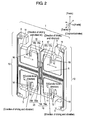
- Fig. 2 shows an operating condition of the detection element of the angular velocity sensor.
- the angular velocity sensor includes detection element 1 for detecting angular velocity.
- Detection element 1 includes two orthogonal arms each formed by connecting one first arm 2 substantially orthogonally to two second arms 4.
- Detection element 1 further includes support portion 6 and fixing arms 8.
- Support portion 6 supports two first arms 2.
- Fixing arms 8 are orthogonal arms formed by connecting first arms 2 substantially orthogonally to third arms 10.
- First arms 2 and support portion 6 are arranged substantially in a straight line.
- First arms 2 are connected at one end thereof to support portion 6 and at the other end thereof to third arms 10.
- Detection element 1 is fixed to mounting substrate (not illustrated) at fixing portions 9 formed at both ends of each of third arms 10.
- Four fixing portions 9 may be connected so as to arrange third arms 10 in a frame shape.
- Second arms 4 include opposing portions 16 formed by bending second arms 4 to face the main portions thereof, and the ends of second arms 4 are connected to weight parts 11.
- Weight parts 11 include recesses 12 to which the ends of second arms 4 are connected. Recesses 12 of weight parts 11 have a depth (D), which is 0.25 times to 0.4 times the length (L) of weight parts 11.
- Fig. 1 two opposite ones of four second arms 4 are provided near support portion 6 with first and second driving portions 17 and 18, respectively, for driving and vibrating weight parts 11 connected thereto.
- the other two opposite ones of four second arms 4 are provided near support portion 6 with first and second sensing portions 19 and 20, respectively, for detecting distortions of the two second arms 4.
- First and second driving portions 17 and 18 are electrode portions for driving weight parts 11 connected to the two second arms 4.
- First driving portion 17 is formed of first and second driving electrode portions 17a and 17b facing each other, whereas second driving portion 18 is formed of third and fourth driving electrode portions 18a and 18b facing each other.
- First to fourth driving electrode portions 17a, 17b, 18a, and 18b are each formed of upper and lower electrodes (both not shown) with a piezoelectric body (not shown) interposed therebetween.
- First and second sensing portions 19 and 20 are electrode portions for detecting distortions of the two second arms 4.
- First sensing portion 19 is formed of first and second sensing electrode portions 19a and 19b facing each other, whereas second sensing portion 20 is formed of third and fourth sensing electrode portions 20a and 20b facing each other.
- First to fourth sensing electrode portions 19a, 19b, 20a, and 20b are each formed of upper and lower electrodes with a piezoelectric body interposed therebetween.
- First to fourth driving electrode portions 17a, 17b, 18a, and 18b, and first to fourth sensing electrode portions 19a, 19b, 20a, and 20b are produced as follows. First, a platinum (Pt) lower electrode is formed on a silicon substrate by radio frequency sputtering. Then, a lead zirconate titanate (PZT) piezoelectric body is formed on the lower electrode by radio frequency sputtering. Finally, a gold (Au) upper electrode is deposited on the PZT piezoelectric body.
- Fig. 2 shows an operating condition of detection element 1 of the angular velocity sensor as one type of inertia force sensor according to the embodiment of the present invention.
- first arms 2 and second arms 4 of detection element 1 are disposed in the x - and y-axis directions, respectively, when x, y, and z are orthogonal axes.
- first to fourth driving electrode portions 17a, 17b, 18a, and 18b When an AC voltage at the resonant frequency is applied to first to fourth driving electrode portions 17a, 17b, 18a, and 18b, second arms 4 start to drive and vibrate, starting from the second arms 4 that have first and second driving portions 17 and 18 thereon.
- Weight parts 11 also start to drive and vibrate in the direction in which second arms 4 face each other (that is, in the direction of driving and vibration shown by the solid arrows and the dotted arrows). After all, four second arms 4 and four weight parts 11 synchronously drive and vibrate in the direction in which second arms 4 face each other.
- the direction of driving and vibration in detection element 1 correspond to the x-axis direction.
- Coriolis force is generated synchronously with the driving and vibration of weight parts 11.
- the Coriolis force is generated in the direction perpendicular to the direction of driving and vibrating weight parts 11 (that is, in the Coriolis force direction shown by the solid and dotted arrows).
- second arms 4 can cause distortions due to the angular velocity generated counterclockwise in the z axis.
- the Coriolis force direction of detection element 1 corresponds to the y-axis direction.
- first and third sensing electrode portions 19a and 20a detect contraction of the second arms 4 that have the sensing electrode portions 19a and 20a thereon
- second and fourth sensing electrode portions 19b and 20b detect expansion of the second arms 4 that have the sensing electrode portions 19b and 20b thereon.
- the first to fourth sensing electrode portions detect expansion and contraction in the opposite directions.
- First to fourth sensing electrode portions 19a, 19b, 20a, and 20b output voltages according to the detected expansion and contraction, so that angular velocities are detected based on the output voltages.
- First to fourth sensing electrode portions 19a, 19b, 20a, and 20b detect the expansion and contraction, so that angular velocities are detected in the same manner as above.
- Second arms 4 can cause distortions due to the angular velocity generated around the y axis.
- First to fourth sensing electrode portions 19a, 19b, 20a, and 20b detect the expansion and contraction of second arms 4, so that angular velocities are detected.
- first to fourth sensing electrode portions 19a, 19b, 20a, and 20b can be also arranged on the second arms 4 that have first to fourth driving electrode portions 17a, 17b, 18a, and 18b.
- first arms 2 and second arms 4 are disposed in the x- and y-axis directions, respectively, when x, y, and z are orthogonal axes.
- Driving and vibrating weight parts 11 in the direction in which second arms 4 face each other can make second arms 4 have distortions due to the angular velocity generated around the y or z axis. Detecting these distortions results in the detection of the angular velocities around the x, y, and z axes. Therefore, in order to detect angular velocities of a plurality of axes, the electronic device is not required to secure an area for mounting a plurality of angular velocity sensors having detection elements. In other words, the electronic device is only required to secure an area for mounting a single detection element, thereby being miniaturized.
- Weight parts 11 include recesses 12 to which the ends of second arms 4 are connected. Second arms 4 are bent to face weight parts 11, and weight parts 11 are driven and vibrated in the direction in which second arms 4 face each other. As a result, the drive frequency can be reduced. Weight parts 11 vibrate while dangling from second arms 4.
- the drive frequency is set to the resonant frequency of detection element 1, and as the resonant frequency becomes larger, the sensitivity decreases.
- the above structure can keep weight parts 11 dangling from second arms 4 and reduce the resonant frequency of detection element 1, thereby reducing the drive frequency of second arms 4. This makes it easy to create the topological design of the circuit, thereby improving the sensitivity.
- Fig. 3 shows changes in the resonant frequency due to the depth (D) of recesses 12 in weight parts 11 and the length (L) of weight parts 11 of detection element 1 of Fig. 1 .
- the depth (D) of recesses 12 in weight parts 11 is preferably 0.25 times to 0.4 times the length (L) of weight parts 11. This is because within this range, the resonant frequency is close to its minimum.
- the drive frequency can be further reduced so as to improve the sensitivity by providing all the arms of detection element 1 with the lower electrode and the piezoelectric body, which are components of first and second driving portions 17, 18 and first and second sensing portions 19, 20.
- the inertia force sensor according to the present invention can detect inertia forces of a plurality of axes, thereby being applicable to various electronic devices.
Landscapes
- Physics & Mathematics (AREA)
- Engineering & Computer Science (AREA)
- General Physics & Mathematics (AREA)
- Radar, Positioning & Navigation (AREA)
- Remote Sensing (AREA)
- Gyroscopes (AREA)
Claims (3)
- Capteur de force d'inertie comprenant :un élément de détection planaire (1), pour détecter une force d'inertie, l'élément de détection (1) comportant :deux bras de fixation (8), ayant chacun un troisième bras (10), dont chacun comprend des parties de fixation (9), qui peuvent être fixées sur un substrat de montage, un au niveau de chaque extrémité dudit troisième bras (10), chacun desdits bras de fixation (8), comportant en outre un premier bras (2), qui est relié de manière perpendiculaire, avec l'une de ses extrémités, au troisième bras respectif (10) à un emplacement situé essentiellement au milieu de chaque bras respectif desdits troisièmes bras (10) et, avec son autre extrémité, à une partie de support centrale (6),lesdits troisièmes bras (10) s'étendant dans une première direction (Y) de deux directions perpendiculaires définissant ledit plan (X-Y) et ledit premier bras (2) s'étendant dans l'autre direction (X) desdites deux directions perpendiculaires,lesdits premiers bras (2) étant agencés, avec ladite partie de support centrale (6) entre eux, dans une ligne droite perpendiculaire auxdits troisièmes bras (10),ledit élément de support central (6) étant en outre relié à deux paires de deuxièmes bras (4) opposées l'une à l'autre, ayant chacune des premières parties s'étendant à l'écart dudit élément de support central (6) dans ladite première direction (Y) ou en face de celle-ci et étant pliée, respectivement, en formant une deuxième partie s'étendant de ladite première partie de chaque deuxième bras dans ladite autre direction (X), lesdits deuxièmes bras (4) étant essentiellement de nouveau pliés en formant des troisièmes parties (16), s'étendant en parallèle auxdites premières parties, et vers lesdits premiers bras (2), de sorte que les deux deuxièmes bras de chacune des paires soient symétriques par rapport à un plan normal à l'autre direction (X) et passant à travers le centre de la partie de supportlesdites troisièmes parties (16) de chacun desdits deuxièmes bras (4) étant reliées à l'une de quatre parties de poids (11),caractérisé en ce quechacune des quatre parties de poids (11) est en forme essentiellement rectangulaire sur le plan (X-Y), un côté de la forme rectangulaire possède un évidement (12) de forme essentiellement rectangulaire ayant une profondeur, et chacune des troisièmes parties (16) est reliée à un fond de l'évidement (12), etD/L est dans une plage de 0,25 à 0,4où D est une profondeur de l'évidement (12) et L est une distance entre le côté de la partie de poids (11) où l'évidement (12) est formé, et un côté de la partie de poids (11) qui s'opposé au côté où l'évidement (12) est formé.
- Capteur de force d'inertie de la revendication 1, dans lequel
l'une des paires de deuxièmes bras (4) reliée de manière linéaire par l'intermédiaire de la partie de support centrale (6) comporte des parties d'entraînement (17, 18) pour entraîner et faire vibrer les parties de poids (11) au niveau de leurs premières parties,
l'autre paire de deuxièmes bras (4) reliée de manière linéaire par l'intermédiaire de la section de support centrale (6) comporte des parties de détection (19, 20) pour détecter des distorsions des deuxièmes bras (4) au niveau de leurs premières parties ; et
les parties d'entraînement (18, 17) et les parties de détection (19, 20) sont chacune formées d'une électrode supérieure et d'une électrode inférieure avec un corps piézoélectrique interposé entre elles. - Capteur de force d'inertie de la revendication 1, dans lequel
l'une des paires de deuxièmes bras (4) reliée de manière linéaire par l'intermédiaire de la partie de support centrale (6) comporte des parties d'entraînement (17, 18) pour entraîner et faire vibrer les parties de poids (11) et les parties de détection (19, 20) pour détecter des distorsions des deuxièmes bras (4) au niveau de leurs premières parties ; et
les parties d'entraînement (17, 18) et les parties de détection (19, 20) sont chacune formées d'une électrode supérieure et d'une électrode inférieure avec un corps piézoélectrique interposé entre elles.
Applications Claiming Priority (2)
| Application Number | Priority Date | Filing Date | Title |
|---|---|---|---|
| JP2006223807A JP5205725B2 (ja) | 2006-08-21 | 2006-08-21 | 角速度センサ |
| PCT/JP2007/066084 WO2008023653A1 (fr) | 2006-08-21 | 2007-08-20 | Capteur de force d'inertie |
Publications (3)
| Publication Number | Publication Date |
|---|---|
| EP2056068A1 EP2056068A1 (fr) | 2009-05-06 |
| EP2056068A4 EP2056068A4 (fr) | 2009-11-25 |
| EP2056068B1 true EP2056068B1 (fr) | 2012-11-14 |
Family
ID=39106739
Family Applications (1)
| Application Number | Title | Priority Date | Filing Date |
|---|---|---|---|
| EP07792698A Not-in-force EP2056068B1 (fr) | 2006-08-21 | 2007-08-20 | Capteur de force d'inertie |
Country Status (5)
| Country | Link |
|---|---|
| US (1) | US20090320594A1 (fr) |
| EP (1) | EP2056068B1 (fr) |
| JP (1) | JP5205725B2 (fr) |
| CN (1) | CN101506617B (fr) |
| WO (1) | WO2008023653A1 (fr) |
Cited By (1)
| Publication number | Priority date | Publication date | Assignee | Title |
|---|---|---|---|---|
| US9605963B2 (en) | 2006-01-24 | 2017-03-28 | Panasonic Intellectual Property Management Co., Ltd. | Inertial force sensor |
Families Citing this family (15)
| Publication number | Priority date | Publication date | Assignee | Title |
|---|---|---|---|---|
| US20100011859A1 (en) * | 2006-09-21 | 2010-01-21 | Panasonic Corporation | Angular velocity sensor |
| US8561467B2 (en) * | 2008-10-07 | 2013-10-22 | Panasonic Corporation | Angular velocity sensor element, angular velocity sensor and angular velocity sensor unit both using angular velocity sensor element, and signal detecting method for angular velocity sensor unit |
| US8689630B2 (en) | 2009-02-13 | 2014-04-08 | Panasonic Corporation | Inertial force sensor and detecting element used for same |
| JP2010190706A (ja) | 2009-02-18 | 2010-09-02 | Panasonic Corp | 慣性力センサ |
| JPWO2011093077A1 (ja) * | 2010-01-29 | 2013-05-30 | パナソニック株式会社 | 角速度センサ |
| WO2011161958A1 (fr) * | 2010-06-25 | 2011-12-29 | パナソニック株式会社 | Élément de détection de force d'inertie et capteur de force d'inertie utilisant cet élément |
| CN103250028A (zh) | 2010-12-28 | 2013-08-14 | 松下电器产业株式会社 | 角速度传感器 |
| JPWO2014122903A1 (ja) * | 2013-02-08 | 2017-01-26 | パナソニックIpマネジメント株式会社 | 電子機器 |
| US9381647B2 (en) * | 2013-02-19 | 2016-07-05 | Seiko Epson Corporation | Force detection device, robot, and moving object |
| JP6125914B2 (ja) * | 2013-06-07 | 2017-05-10 | 日立オートモティブシステムズ株式会社 | 角速度センサ |
| JP6344033B2 (ja) * | 2014-04-22 | 2018-06-20 | セイコーエプソン株式会社 | 角速度センサー、電子機器及び移動体 |
| JP6696530B2 (ja) | 2017-05-24 | 2020-05-20 | 株式会社村田製作所 | 圧電ジャイロスコープにおける連結懸架 |
| JP6627911B2 (ja) | 2017-05-24 | 2020-01-08 | 株式会社村田製作所 | 圧電回転mems共振器 |
| JP6627912B2 (ja) | 2017-05-24 | 2020-01-08 | 株式会社村田製作所 | 圧電回転mems共振器 |
| JP6610706B2 (ja) | 2017-05-24 | 2019-11-27 | 株式会社村田製作所 | 横駆動変換器を備える圧電ジャイロスコープ |
Citations (1)
| Publication number | Priority date | Publication date | Assignee | Title |
|---|---|---|---|---|
| EP1860402A1 (fr) * | 2006-05-24 | 2007-11-28 | Hitachi Metals, Ltd. | Capteur de débit angulaire |
Family Cites Families (31)
| Publication number | Priority date | Publication date | Assignee | Title |
|---|---|---|---|---|
| JP3323361B2 (ja) * | 1995-05-29 | 2002-09-09 | アルプス電気株式会社 | 振動型ジャイロスコープ |
| SE9500729L (sv) * | 1995-02-27 | 1996-08-28 | Gert Andersson | Anordning för mätning av vinkelhastighet i enkristallint material samt förfarande för framställning av sådan |
| DE19508769C1 (de) | 1995-03-01 | 1996-08-29 | Siemens Ag | Verfahren zur Bestimmung des Drehsinnes eines Drehstromnetzes und Schaltungsanordnung zur Durchführung des Verfahrens |
| JPH08152328A (ja) * | 1995-07-04 | 1996-06-11 | Nippondenso Co Ltd | 角速度センサ及びその使用方法 |
| JPH09105634A (ja) * | 1995-10-12 | 1997-04-22 | Nippon Soken Inc | 角速度センサ |
| JPH09178492A (ja) * | 1995-12-27 | 1997-07-11 | Kyocera Corp | 圧電振動体 |
| EP0939296A3 (fr) * | 1996-03-29 | 2001-01-17 | Ngk Insulators, Ltd. | Capteur gyroscopique à vibration, capteur combiné, et sa méthode de fabrication |
| JPH1047966A (ja) * | 1996-07-31 | 1998-02-20 | Aisin Seiki Co Ltd | 角速度センサ |
| JPH1047971A (ja) * | 1996-08-05 | 1998-02-20 | Nippon Soken Inc | 角速度センサ |
| JP3336605B2 (ja) * | 1997-02-12 | 2002-10-21 | トヨタ自動車株式会社 | 角速度センサ |
| JP3355998B2 (ja) * | 1997-05-16 | 2002-12-09 | 株式会社村田製作所 | 振動ジャイロ |
| EP0943903B1 (fr) * | 1997-09-08 | 2004-11-24 | Ngk Insulators, Ltd. | Detecteur de masse et procede de detection de masse |
| JP4004129B2 (ja) * | 1998-02-09 | 2007-11-07 | マイクロストーン株式会社 | 運動センサ |
| JP4112684B2 (ja) * | 1998-06-01 | 2008-07-02 | シチズンホールディングス株式会社 | 振動ジャイロ |
| JP2000074673A (ja) * | 1998-08-27 | 2000-03-14 | Miyota Kk | 複合運動センサ |
| JP3998049B2 (ja) * | 1999-09-13 | 2007-10-24 | 芳明 加藤 | 運動センサ振動体および振動ジャイロスコープ |
| FR2798993B1 (fr) * | 1999-09-28 | 2001-12-07 | Thomson Csf Sextant | Gyrometre de type diapason |
| DE60028696T2 (de) * | 1999-11-09 | 2007-05-24 | Alps Electric Co., Ltd. | Kreisel und Eingabevorrichtung |
| JP2001194155A (ja) * | 2000-01-13 | 2001-07-19 | Yoshiro Tomikawa | 運動センサ |
| JP4552253B2 (ja) * | 2000-02-28 | 2010-09-29 | パナソニック株式会社 | 角速度センサ |
| FR2812386B1 (fr) * | 2000-07-28 | 2002-11-15 | Sagem | Gyrometre a poutres vibrantes, a excitation piezo-electrique |
| JP4305623B2 (ja) * | 2002-03-13 | 2009-07-29 | セイコーエプソン株式会社 | 振動子および振動型ジャイロスコープ |
| JP2004077351A (ja) * | 2002-08-21 | 2004-03-11 | Matsushita Electric Ind Co Ltd | 角速度センサ |
| JP4163031B2 (ja) * | 2003-03-28 | 2008-10-08 | 日本電波工業株式会社 | 音叉型角速度センサ |
| JP2005283402A (ja) * | 2004-03-30 | 2005-10-13 | Fujitsu Media Device Kk | 慣性センサ |
| JP2006030125A (ja) * | 2004-07-21 | 2006-02-02 | Fujitsu Media Device Kk | 角速度センサ |
| JP4687085B2 (ja) * | 2004-12-03 | 2011-05-25 | パナソニック株式会社 | 複合センサ |
| JP4415382B2 (ja) * | 2005-01-20 | 2010-02-17 | セイコーエプソン株式会社 | 振動ジャイロ素子、振動ジャイロ素子の支持構造およびジャイロセンサ |
| JP2006266969A (ja) * | 2005-03-25 | 2006-10-05 | Nec Tokin Corp | 音叉形圧電振動ジャイロ |
| JP4702942B2 (ja) * | 2005-10-14 | 2011-06-15 | Necトーキン株式会社 | 振動ジャイロ用素子及び振動ジャイロ |
| JP2007327758A (ja) * | 2006-06-06 | 2007-12-20 | Nec Tokin Corp | 圧電単結晶振動子および圧電振動ジャイロ |
-
2006
- 2006-08-21 JP JP2006223807A patent/JP5205725B2/ja not_active Expired - Fee Related
-
2007
- 2007-08-20 WO PCT/JP2007/066084 patent/WO2008023653A1/fr not_active Ceased
- 2007-08-20 EP EP07792698A patent/EP2056068B1/fr not_active Not-in-force
- 2007-08-20 US US12/374,717 patent/US20090320594A1/en not_active Abandoned
- 2007-08-20 CN CN2007800308218A patent/CN101506617B/zh not_active Expired - Fee Related
Patent Citations (1)
| Publication number | Priority date | Publication date | Assignee | Title |
|---|---|---|---|---|
| EP1860402A1 (fr) * | 2006-05-24 | 2007-11-28 | Hitachi Metals, Ltd. | Capteur de débit angulaire |
Cited By (2)
| Publication number | Priority date | Publication date | Assignee | Title |
|---|---|---|---|---|
| US9605963B2 (en) | 2006-01-24 | 2017-03-28 | Panasonic Intellectual Property Management Co., Ltd. | Inertial force sensor |
| US10408618B2 (en) | 2006-01-24 | 2019-09-10 | Panasonic Intellectual Property Management Co., Ltd. | Angular velocity sensor |
Also Published As
| Publication number | Publication date |
|---|---|
| EP2056068A1 (fr) | 2009-05-06 |
| US20090320594A1 (en) | 2009-12-31 |
| EP2056068A4 (fr) | 2009-11-25 |
| WO2008023653A1 (fr) | 2008-02-28 |
| CN101506617B (zh) | 2011-11-30 |
| JP5205725B2 (ja) | 2013-06-05 |
| CN101506617A (zh) | 2009-08-12 |
| JP2008046058A (ja) | 2008-02-28 |
Similar Documents
| Publication | Publication Date | Title |
|---|---|---|
| EP2056068A1 (fr) | Capteur de force d'inertie | |
| EP2899502B1 (fr) | Capteur de force d'inertie | |
| US8061203B2 (en) | Combined sensor | |
| EP2113744A1 (fr) | Capteur de force d'inertie et capteur composite servant à détecter la force d'inertie | |
| JPH10239347A (ja) | 運動センサ | |
| US8074517B2 (en) | Inertia force sensor | |
| JP2007256235A (ja) | 慣性力センサ | |
| JP2012149961A (ja) | 振動ジャイロ | |
| WO2019044696A1 (fr) | Capteur de vitesse angulaire et élément de capteur | |
| CN102292615A (zh) | 惯性力传感器及其使用的检测元件 | |
| JP4687085B2 (ja) | 複合センサ | |
| US20100011859A1 (en) | Angular velocity sensor | |
| JP2004125458A (ja) | 音叉型圧電振動片及び圧電振動ジャイロ | |
| JP2007198778A (ja) | 慣性力センサ | |
| JP2009250955A (ja) | 慣性力センサ | |
| HK1125445A (en) | Inertial force sensor | |
| JP2007198779A (ja) | 慣性力センサ | |
| JP2007198775A (ja) | 慣性力センサ | |
| JP2007198774A (ja) | 慣性力センサ | |
| JP2007198780A (ja) | 慣性力センサ |
Legal Events
| Date | Code | Title | Description |
|---|---|---|---|
| PUAI | Public reference made under article 153(3) epc to a published international application that has entered the european phase |
Free format text: ORIGINAL CODE: 0009012 |
|
| 17P | Request for examination filed |
Effective date: 20090115 |
|
| AK | Designated contracting states |
Kind code of ref document: A1 Designated state(s): AT BE BG CH CY CZ DE DK EE ES FI FR GB GR HU IE IS IT LI LT LU LV MC MT NL PL PT RO SE SI SK TR |
|
| AX | Request for extension of the european patent |
Extension state: AL BA HR MK RS |
|
| DAX | Request for extension of the european patent (deleted) | ||
| RBV | Designated contracting states (corrected) |
Designated state(s): DE FR GB |
|
| A4 | Supplementary search report drawn up and despatched |
Effective date: 20091027 |
|
| 17Q | First examination report despatched |
Effective date: 20101105 |
|
| REG | Reference to a national code |
Ref country code: DE Ref legal event code: R079 Ref document number: 602007026711 Country of ref document: DE Free format text: PREVIOUS MAIN CLASS: G01C0019560000 Ipc: G01C0019574000 |
|
| GRAP | Despatch of communication of intention to grant a patent |
Free format text: ORIGINAL CODE: EPIDOSNIGR1 |
|
| RIC1 | Information provided on ipc code assigned before grant |
Ipc: G01C 19/574 20120101AFI20120627BHEP Ipc: H01L 41/08 20060101ALI20120627BHEP |
|
| GRAS | Grant fee paid |
Free format text: ORIGINAL CODE: EPIDOSNIGR3 |
|
| GRAA | (expected) grant |
Free format text: ORIGINAL CODE: 0009210 |
|
| AK | Designated contracting states |
Kind code of ref document: B1 Designated state(s): DE FR GB |
|
| REG | Reference to a national code |
Ref country code: GB Ref legal event code: FG4D |
|
| REG | Reference to a national code |
Ref country code: DE Ref legal event code: R096 Ref document number: 602007026711 Country of ref document: DE Effective date: 20130110 |
|
| PLBE | No opposition filed within time limit |
Free format text: ORIGINAL CODE: 0009261 |
|
| STAA | Information on the status of an ep patent application or granted ep patent |
Free format text: STATUS: NO OPPOSITION FILED WITHIN TIME LIMIT |
|
| 26N | No opposition filed |
Effective date: 20130815 |
|
| REG | Reference to a national code |
Ref country code: DE Ref legal event code: R097 Ref document number: 602007026711 Country of ref document: DE Effective date: 20130815 |
|
| PGFP | Annual fee paid to national office [announced via postgrant information from national office to epo] |
Ref country code: GB Payment date: 20140820 Year of fee payment: 8 Ref country code: FR Payment date: 20140821 Year of fee payment: 8 |
|
| PGFP | Annual fee paid to national office [announced via postgrant information from national office to epo] |
Ref country code: DE Payment date: 20150821 Year of fee payment: 9 |
|
| GBPC | Gb: european patent ceased through non-payment of renewal fee |
Effective date: 20150820 |
|
| REG | Reference to a national code |
Ref country code: FR Ref legal event code: ST Effective date: 20160429 |
|
| PG25 | Lapsed in a contracting state [announced via postgrant information from national office to epo] |
Ref country code: GB Free format text: LAPSE BECAUSE OF NON-PAYMENT OF DUE FEES Effective date: 20150820 |
|
| PG25 | Lapsed in a contracting state [announced via postgrant information from national office to epo] |
Ref country code: FR Free format text: LAPSE BECAUSE OF NON-PAYMENT OF DUE FEES Effective date: 20150831 |
|
| REG | Reference to a national code |
Ref country code: DE Ref legal event code: R119 Ref document number: 602007026711 Country of ref document: DE |
|
| PG25 | Lapsed in a contracting state [announced via postgrant information from national office to epo] |
Ref country code: DE Free format text: LAPSE BECAUSE OF NON-PAYMENT OF DUE FEES Effective date: 20170301 |