EP2192322B1 - Élément absorbant les chocs - Google Patents
Élément absorbant les chocs Download PDFInfo
- Publication number
- EP2192322B1 EP2192322B1 EP08838249.4A EP08838249A EP2192322B1 EP 2192322 B1 EP2192322 B1 EP 2192322B1 EP 08838249 A EP08838249 A EP 08838249A EP 2192322 B1 EP2192322 B1 EP 2192322B1
- Authority
- EP
- European Patent Office
- Prior art keywords
- fiber
- reinforced resin
- impact
- absorbing member
- leading portion
- Prior art date
- Legal status (The legal status is an assumption and is not a legal conclusion. Google has not performed a legal analysis and makes no representation as to the accuracy of the status listed.)
- Not-in-force
Links
- 230000035939 shock Effects 0.000 title description 2
- 229920005989 resin Polymers 0.000 claims description 165
- 239000011347 resin Substances 0.000 claims description 165
- 239000012783 reinforcing fiber Substances 0.000 claims description 41
- 238000010521 absorption reaction Methods 0.000 claims description 15
- 238000006073 displacement reaction Methods 0.000 claims description 5
- 239000010410 layer Substances 0.000 description 133
- 239000000835 fiber Substances 0.000 description 21
- 239000000805 composite resin Substances 0.000 description 19
- 238000010030 laminating Methods 0.000 description 11
- 239000000463 material Substances 0.000 description 8
- 230000007704 transition Effects 0.000 description 8
- 238000010586 diagram Methods 0.000 description 6
- 239000003822 epoxy resin Substances 0.000 description 5
- 239000000203 mixture Substances 0.000 description 5
- 229920000647 polyepoxide Polymers 0.000 description 5
- 229920001721 polyimide Polymers 0.000 description 5
- 239000009719 polyimide resin Substances 0.000 description 5
- ZOXJGFHDIHLPTG-UHFFFAOYSA-N Boron Chemical compound [B] ZOXJGFHDIHLPTG-UHFFFAOYSA-N 0.000 description 4
- 229920000049 Carbon (fiber) Polymers 0.000 description 4
- 229920000271 Kevlar® Polymers 0.000 description 4
- PNEYBMLMFCGWSK-UHFFFAOYSA-N aluminium oxide Inorganic materials [O-2].[O-2].[O-2].[Al+3].[Al+3] PNEYBMLMFCGWSK-UHFFFAOYSA-N 0.000 description 4
- 239000004760 aramid Substances 0.000 description 4
- 229920006231 aramid fiber Polymers 0.000 description 4
- 229920003235 aromatic polyamide Polymers 0.000 description 4
- 229910052796 boron Inorganic materials 0.000 description 4
- 239000004917 carbon fiber Substances 0.000 description 4
- 239000000919 ceramic Substances 0.000 description 4
- 239000002131 composite material Substances 0.000 description 4
- 238000005520 cutting process Methods 0.000 description 4
- 239000004643 cyanate ester Substances 0.000 description 4
- 239000003365 glass fiber Substances 0.000 description 4
- 238000010438 heat treatment Methods 0.000 description 4
- 239000003999 initiator Substances 0.000 description 4
- 239000004761 kevlar Substances 0.000 description 4
- VNWKTOKETHGBQD-UHFFFAOYSA-N methane Chemical compound C VNWKTOKETHGBQD-UHFFFAOYSA-N 0.000 description 4
- 238000000465 moulding Methods 0.000 description 4
- 229920000728 polyester Polymers 0.000 description 4
- 229920001225 polyester resin Polymers 0.000 description 4
- 239000004645 polyester resin Substances 0.000 description 4
- HBMJWWWQQXIZIP-UHFFFAOYSA-N silicon carbide Chemical compound [Si+]#[C-] HBMJWWWQQXIZIP-UHFFFAOYSA-N 0.000 description 4
- 229910010271 silicon carbide Inorganic materials 0.000 description 4
- 239000004952 Polyamide Substances 0.000 description 3
- 239000003795 chemical substances by application Substances 0.000 description 3
- 229920001971 elastomer Polymers 0.000 description 3
- 239000004744 fabric Substances 0.000 description 3
- 239000011229 interlayer Substances 0.000 description 3
- 238000000034 method Methods 0.000 description 3
- 229920002647 polyamide Polymers 0.000 description 3
- 229920001187 thermosetting polymer Polymers 0.000 description 3
- 230000006378 damage Effects 0.000 description 2
- 230000003247 decreasing effect Effects 0.000 description 2
- 239000000806 elastomer Substances 0.000 description 2
- 230000001939 inductive effect Effects 0.000 description 2
- 238000004519 manufacturing process Methods 0.000 description 2
- -1 polyethylene terephthalate Polymers 0.000 description 2
- 239000005060 rubber Substances 0.000 description 2
- 238000000926 separation method Methods 0.000 description 2
- 230000003068 static effect Effects 0.000 description 2
- 229920002725 thermoplastic elastomer Polymers 0.000 description 2
- VZXTWGWHSMCWGA-UHFFFAOYSA-N 1,3,5-triazine-2,4-diamine Chemical compound NC1=NC=NC(N)=N1 VZXTWGWHSMCWGA-UHFFFAOYSA-N 0.000 description 1
- XQUPVDVFXZDTLT-UHFFFAOYSA-N 1-[4-[[4-(2,5-dioxopyrrol-1-yl)phenyl]methyl]phenyl]pyrrole-2,5-dione Chemical compound O=C1C=CC(=O)N1C(C=C1)=CC=C1CC1=CC=C(N2C(C=CC2=O)=O)C=C1 XQUPVDVFXZDTLT-UHFFFAOYSA-N 0.000 description 1
- KXGFMDJXCMQABM-UHFFFAOYSA-N 2-methoxy-6-methylphenol Chemical compound [CH]OC1=CC=CC([CH])=C1O KXGFMDJXCMQABM-UHFFFAOYSA-N 0.000 description 1
- 229920001634 Copolyester Polymers 0.000 description 1
- 229920000459 Nitrile rubber Polymers 0.000 description 1
- 229920000571 Nylon 11 Polymers 0.000 description 1
- 229920002292 Nylon 6 Polymers 0.000 description 1
- 229920000305 Nylon 6,10 Polymers 0.000 description 1
- 229920002302 Nylon 6,6 Polymers 0.000 description 1
- 229920000572 Nylon 6/12 Polymers 0.000 description 1
- 239000004696 Poly ether ether ketone Substances 0.000 description 1
- 239000004962 Polyamide-imide Substances 0.000 description 1
- 239000004721 Polyphenylene oxide Substances 0.000 description 1
- 239000004734 Polyphenylene sulfide Substances 0.000 description 1
- 229920006311 Urethane elastomer Polymers 0.000 description 1
- 229920000800 acrylic rubber Polymers 0.000 description 1
- 229920003180 amino resin Polymers 0.000 description 1
- 238000006243 chemical reaction Methods 0.000 description 1
- 230000032798 delamination Effects 0.000 description 1
- 229920001973 fluoroelastomer Polymers 0.000 description 1
- 239000007849 furan resin Substances 0.000 description 1
- 238000003475 lamination Methods 0.000 description 1
- 229920001568 phenolic resin Polymers 0.000 description 1
- 239000005011 phenolic resin Substances 0.000 description 1
- XNGIFLGASWRNHJ-UHFFFAOYSA-L phthalate(2-) Chemical compound [O-]C(=O)C1=CC=CC=C1C([O-])=O XNGIFLGASWRNHJ-UHFFFAOYSA-L 0.000 description 1
- 229920003192 poly(bis maleimide) Polymers 0.000 description 1
- 229920002492 poly(sulfone) Polymers 0.000 description 1
- 229920000058 polyacrylate Polymers 0.000 description 1
- 229920002312 polyamide-imide Polymers 0.000 description 1
- 229920001707 polybutylene terephthalate Polymers 0.000 description 1
- 229920000515 polycarbonate Polymers 0.000 description 1
- 239000004417 polycarbonate Substances 0.000 description 1
- 229920006393 polyether sulfone Polymers 0.000 description 1
- 229920002530 polyetherether ketone Polymers 0.000 description 1
- 229920001601 polyetherimide Polymers 0.000 description 1
- 229920000139 polyethylene terephthalate Polymers 0.000 description 1
- 239000005020 polyethylene terephthalate Substances 0.000 description 1
- 229920000098 polyolefin Polymers 0.000 description 1
- 229920006380 polyphenylene oxide Polymers 0.000 description 1
- 229920000069 polyphenylene sulfide Polymers 0.000 description 1
- 229920005749 polyurethane resin Polymers 0.000 description 1
- KCTAWXVAICEBSD-UHFFFAOYSA-N prop-2-enoyloxy prop-2-eneperoxoate Chemical compound C=CC(=O)OOOC(=O)C=C KCTAWXVAICEBSD-UHFFFAOYSA-N 0.000 description 1
- 230000003014 reinforcing effect Effects 0.000 description 1
- 229920002379 silicone rubber Polymers 0.000 description 1
- 239000004945 silicone rubber Substances 0.000 description 1
- 229920003048 styrene butadiene rubber Polymers 0.000 description 1
- 229920005992 thermoplastic resin Polymers 0.000 description 1
- 229920006337 unsaturated polyester resin Polymers 0.000 description 1
- 229920001567 vinyl ester resin Polymers 0.000 description 1
Images




Classifications
-
- F—MECHANICAL ENGINEERING; LIGHTING; HEATING; WEAPONS; BLASTING
- F16—ENGINEERING ELEMENTS AND UNITS; GENERAL MEASURES FOR PRODUCING AND MAINTAINING EFFECTIVE FUNCTIONING OF MACHINES OR INSTALLATIONS; THERMAL INSULATION IN GENERAL
- F16F—SPRINGS; SHOCK-ABSORBERS; MEANS FOR DAMPING VIBRATION
- F16F7/00—Vibration-dampers; Shock-absorbers
- F16F7/12—Vibration-dampers; Shock-absorbers using plastic deformation of members
- F16F7/124—Vibration-dampers; Shock-absorbers using plastic deformation of members characterised by their special construction from fibre-reinforced plastics
Definitions
- the present invention relates to an impact-absorbing member and, for example, to an impact-absorbing member suitable for use in flying objects such as aircraft and driving objects such as automobiles.
- a known example of an impact-absorbing member that is used in flying objects (traveling objects) such as aircraft and driving objects (traveling objects) such as automobiles and that has an impact-absorbing ability to alleviate an excessive initial rise in reaction force occurring during transition to a fracture mode is the energy-absorbing member disclosed in Patent Document 1.
- Patent Document 2 discloses an impact-absorbing composite structure that can control the progress of destruction while absorbing the impact by self-destruction, the impact-absorbing composite structure being formed with a resin and a fiber-laminated body and comprising an interlayer reinforcing area obtained by applying needling, stitching or a three-dimensional fabric to the impact-absorbing composite structure.
- the needling, stitching or three-dimensional fabric is not applied from the end portion of the impact-absorbing composite structure up to a predetermined position.
- Patent Document 3 discloses a cylindrical energy-absorbing member comprising a plurality of fiber-reinforcing layers and a plurality of separation assistant layers, the latter being embedded between the fiber-reinforced layers into one end part in the longitudinal direction of the energy-absorbing member.
- reinforcing fibers in fiber-reinforced resin layers at the center in the thickness direction extend in a direction falling within the range of 90° ⁇ 15° with respect to an energy-absorption axis direction. Therefore, if a load is applied to the energy-absorbing member in the axial direction thereof, a fracture proceeds easily in the axial direction in the fiber-reinforced resin layers themselves at the center in the thickness direction, as well as between these fiber-reinforced resin layers and fiber-reinforced resin layers disposed adjacent thereto, and the load received by the energy-absorbing member as the self-fracture proceeds is significantly decreased, thus resulting in the problem of a significantly decreased amount of absorbed energy.
- An object of the present invention which has been made in light of the above circumstances, is to provide an impact-absorbing member that allows control of the peak value of an initial load in a self-fracture occurring during transition to a stable sequential fracture mode and that can ensure a desired amount of absorbed energy.
- the invention thus relates to an impact-absorbing member as defined in claim 1 .
- the impact-absorbing member includes a main body including a plurality of fiber-reinforced resin layers that absorb an impact through self-fracture when subjected to the impact, and a leading portion including a plurality of fiber-reinforced resin layers that absorb the impact through self-fracture when subjected to the impact, the leading portion fracturing initially when subjected to the impact.
- at least one of the fiber-reinforced resin layers of the leading portion has reinforced fibers oriented at an angular difference of 10° or more with respect to an energy-absorption axis direction.
- the main body has a higher strength and elastic modulus in the energy-absorption axis direction than the leading portion, and at least one of the fiber-reinforced resin layers of the main body and at least one of the fiber-reinforced resin layers of the leading portion is the same fiber-reinforced resin layer.
- the fiber-reinforced resin layers of the main body and the fiber-reinforced resin layers of the leading portion which are included in the same fiber-reinforced resin layer have the reinforcing fibers in the fiber-reinforced resin layers of the main body oriented at an angle within a range of 0° ⁇ 45° with respect to the energy-absorption axis direction, and have the reinforcing fibers in the fiber-reinforced resin layers of the leading portion (3a) oriented at an angle within a range of 90° ⁇ 45° with respect to the energy-absorption axis direction.
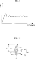
- the leading portion which has a lower strength in the axial direction than the main body, fractures earlier in the initial stage of self-fracture, and the main body then fractures in the middle and terminal stages of self-fracture. That is, for example, as shown in Fig. 4 , it is possible to control the peak value of the initial load occurring in the impact-absorbing member during transition to a stable sequential fracture mode.
- the peak value of the initial load on the impact-absorbing member of the invention and the value of the predetermined load at which a self-fracture proceeds can be freely set to desired values by changing the composition of the fiber-reinforced resin composite constituting the impact-absorbing member (that is, the materials of the reinforcing fibers and the resin), by providing the leading portion at one or the other end, or both ends, of the impact-absorbing member, or by adjusting the length L1, L2 or L3 (see Figs. 3 , 5 and 6 ) of the leading portion.
- the peak value of the initial load and the value of the predetermined load at which a self-fracture proceeds can be more finely set by orienting the reinforcing fibers in at least one of the fiber-reinforced resin layers at the leading portion within the range of 90° ⁇ 45° with respect to the energy-absorption axis direction and orienting the reinforcing fibers in the same fiber-reinforced resin layer in the main body within the range of 0° ⁇ 45° with respect to the energy-absorption axis direction, thus further extending the design flexibility of the impact-absorbing member.
- the leading portion may be formed by gradually applying a load crushing the portion in a direction of an energy-absorption axis and stopping the crushing by the load when displacement of the fiber-reinforced resin layers reaches a desired value.
- the reinforcing fibers of the leading portion may meander locally so as to protrude inward or outward with respect to a circumferential direction, or may meander locally inward with respect to the circumferential direction.
- the invention in a second aspect, relates to a crashworthy structural member as defined in claim 4.
- the crashworthy structural member includes the impact-absorbing member according to the first aspect, which can eliminate a harmful peak value of the initial load occurring in the initial stage of self-fracture and which can maintain the impact load in the middle and terminal stages of self-fracture for a predetermined period of time so that the fracture proceeds at a predetermined load (for example, near the average load).
- a crashworthy structural member include floor structures of flying objects, such as helicopters and aircraft, and land-driven objects.
- an impact due to a collision or crash is absorbed by the impact-absorbing member, which has superior impact-energy absorbing capability, so that it can ensure a good chance of the occupants surviving even if an unforeseen impact is encountered in the event of, for example, a collision or crash.
- the invention in a third aspect, relates to a traveling object as defined in claim 5.
- the traveling object includes the crashworthy structural member according to the second aspect, which can eliminate a harmful peak value of the initial load occurring in the initial stage of self-fracture and which can maintain the impact load in the middle and terminal stages of self-fracture for a predetermined period of time so that the fracture proceeds at a predetermined load (for example, near the average load).
- an impact due to a collision or crash is absorbed by the crashworthy structural member, which has superior impact-energy absorbing capability, so that it can ensure a good chance of the occupants surviving even if an unforeseen impact is encountered in the event of, for example, a collision or crash.
- the present invention provides an advantage in that it allows control of the peak value of an initial load in a self-fracture occurring during transition to a stable sequential fracture mode and can ensure a desired amount of absorbed energy.
- Fig. 1 is a perspective view showing the fuselage frame structure of a helicopter including the impact-absorbing member of the present invention
- Fig. 2 is a schematic overall perspective view of the impact-absorbing member of the present invention
- Fig. 3 is a sectional view taken along arrow a-a of Fig. 2
- Fig. 4 is a graph showing the relationship between the impact load imposed on the impact-absorbing member of the present invention and the displacement thereof.
- the impact-absorbing member (also referred to as "impact-absorbing tube”) of the present invention can be applied to, for example, a floor structure 2 of a helicopter (rotorcraft) 1, as shown in Fig. 1 .
- the impact-absorbing member 3 has an external appearance like, for example, a hollow rectangular column (square column in this embodiment), as shown in Fig. 2 , and is formed of, for example, a fiber-reinforced resin composite prepared by laminating a required number of (in this embodiment, seven) sheet-shaped prepregs formed by impregnating reinforcing fiber (reinforcing fiber formed of, for example, carbon fiber, glass fiber, aramid fiber (e.g., Kevlar (registered trademark)), ceramic fiber, aromatic polyamide fiber, alumina fiber, silicon carbide fiber, or boron fiber) in advance with a resin (such as epoxy resin, polyester resin, cyanate ester resin, or polyimide resin), followed by molding them under pressure in a heating furnace (autoclave) (not shown).
- a resin such as epoxy resin, polyester resin, cyanate ester resin, or polyimide resin
- the impact-absorbing member 3 includes a leading portion (also referred to as "initiator portion", which means a portion serving as the origin of fracture) 3a constituting an end (one end (top end) and/or the other end (bottom end)) in an energy-absorption axis direction (hereinafter referred to as "axial direction”) and an impact-absorbing-member main body (hereinafter referred to as "main body”) 3b constituting the other portion.
- the leading portion 3a is provided in the circumferential direction over a length L1 (for example, 5 to 10 mm) from a leading (terminal) end (leading surface if chamfering (45° taper cutting: chamfer cutting), as shown in Fig. 3 , is not performed) of the impact-absorbing member 3 toward the main body 3b (toward the center of the main body 3b) .
- the fiber-reinforced resin composite constituting the leading portion 3a is prepared by, for example, as shown in Fig. 3 , sequentially laminating a +45° fiber-reinforced resin layer 4 whose reinforcing fibers (not shown) are oriented at an inclination of +45° with respect to the axial direction, a 90° fiber-reinforced resin layer 5 whose reinforcing fibers are oriented at an inclination of 90° (perpendicularly) with respect to the axial direction (vertical direction in Fig.
- a -45° fiber-reinforced resin layer 6 whose reinforcing fibers are oriented at an inclination of -45° with respect to the axial direction, a 90° fiber-reinforced resin layer 5, a -45° fiber-reinforced resin layer 6, a 90° fiber-reinforced resin layer 5, and a +45° fiber-reinforced resin layer 4.
- the fiber-reinforced resin composite constituting the main body 3b is prepared by, for example, as shown in Fig. 3 , sequentially laminating a +45° fiber-reinforced resin layer 4 whose reinforcing fibers are oriented at an inclination of +45° with respect to the axial direction (vertical direction in Fig.
- a 0° fiber-reinforced resin layer 7 whose reinforcing fibers are oriented in the axial direction (that is, oriented without inclination with respect to the axial direction), a -45° fiber-reinforced resin layer 6 whose reinforcing fibers are oriented at an inclination of -45° with respect to the axial direction, a 0° fiber-reinforced resin layer 7, a -45° fiber-reinforced resin layer 6, a 0° fiber-reinforced resin layer 7, and a +45° fiber-reinforced resin layer 4.
- the leading portion 3a which has a lower strength in the axial direction than the main body 3b, fractures earlier in the initial stage of self-fracture, and the main body 3b then fractures in the middle and terminal stages of self-fracture. That is, as shown in Fig. 4 , it is possible to control the peak value of the initial load occurring in the impact-absorbing member 3 during transition to a stable sequential fracture mode. In other words, it is possible to eliminate a harmful peak value of the initial load occurring in the initial stage of self-fracture and to maintain the impact load in the middle and terminal stages of self-fracture for a predetermined period of time so that the fracture proceeds at a predetermined load (for example, near the average load).
- a predetermined load for example, near the average load
- the peak value of the initial load on the impact-absorbing member 3 and the value of the predetermined load at which a self-fracture proceeds can be freely set to desired values by changing the composition of the fiber-reinforced resin composite constituting the impact-absorbing member 3 (that is, the materials of the reinforcing fibers and the resin), by providing the leading portion 3a at one or the other end, or both ends, of the impact-absorbing member 3, or by adjusting the length L1 of the leading portion 3a.
- a (crushing) fracture test carried out by applying a load to the impact-absorbing member 3 in the axial direction under dynamic conditions yielded test results showing that an impact-absorbing member 3 formed of a certain fiber-reinforced resin composite had a load homogeneity ratio (the initial peak load (kN) divided by the average load (kN)) of 0.84 to 0.87.
- the leading portion 3a including the +45° fiber-reinforced resin layer 4 the 90° fiber-reinforced resin layer 5, the -45° fiber-reinforced resin layer 6, the 90° fiber-reinforced resin layer 5, the -45° fiber-reinforced resin layer 6, the 90° fiber-reinforced resin layer 5, and the +45° fiber-reinforced resin layer 4 has been described as a specific example, the present invention is not limited thereto.
- the 90° fiber-reinforced resin layers 5 are replaced with 90° ⁇ 45° fiber-reinforced resin layers whose reinforcing fibers (not shown) are oriented at an inclination of +45° to +90° or -45° to -90° with respect to the axial direction, and can be replaced with 90° ⁇ 15° fiber-reinforced resin layers, 90° ⁇ 5° fiber-reinforced resin layers, or 90° ⁇ 1° fiber-reinforced resin layers.
- the fiber-reinforced resin layers that replace the 90° fiber-reinforced resin layers 5 are not limited to 90° ⁇ 45° fiber-reinforced resin layers; any fiber-reinforced resin layers falling within the range of 90° ⁇ 45° may be used.
- the main body 3b including the +45° fiber-reinforced resin layer 4, the 0° fiber-reinforced resin layer 7, the -45° fiber-reinforced resin layer 6, the 0° fiber-reinforced resin layer 7, the -45° fiber-reinforced resin layer 6, the 0° fiber-reinforced resin layer 7, and the +45° fiber-reinforced resin layer 4 has been described as a specific example, the present invention is not limited thereto.
- the 0° fiber-reinforced resin layers 7 are replaced with 0° ⁇ 45° fiber-reinforced resin layers whose reinforcing fibers (not shown) are oriented at an inclination of 0° to +45° or 0° to -45° with respect to the axial direction, and can be replaced with 0° ⁇ 15° fiber-reinforced resin layers, 0° ⁇ 5° fiber-reinforced resin layers, or 0° ⁇ 1° fiber-reinforced resin layers.
- the fiber-reinforced resin layers that replace the 0° fiber-reinforced resin layers 7 are not limited to 0° ⁇ 45° fiber-reinforced resin layers; any fiber-reinforced resin layers falling within the range of 0° ⁇ 45° can be used.
- a first reference impact-absorbing member will be described with reference to Figs. 2 , 4, and 5 .
- Fig. 5 is a diagram, similar to Fig. 3 , showing the first reference impact-absorbing member .
- the first reference impact-absorbing member 10 has an external appearance like, for example, a hollow rectangular column (square column in this case), as shown in Fig. 2 , and is formed of, for example, a fiber-reinforced resin composite prepared by laminating a required number of (in this case, seven) sheet-shaped prepregs formed by impregnating reinforcing fiber (reinforcing fiber formed of, for example, carbon fiber, glass fiber, aramid fiber (e.g., Kevlar (registered trademark)), ceramic fiber, aromatic polyamide fiber, alumina fiber, silicon carbide fiber, or boron fiber) in advance with a resin (such as epoxy resin, polyester resin, cyanate ester resin, or polyimide resin), followed by molding them under pressure in a heating furnace (autoclave) (not shown).
- a resin such as epoxy resin, polyester resin, cyanate ester resin, or polyimide resin
- the impact-absorbing member 10 includes a leading portion (also referred to as “initiator portion” or “fracture portion”) 10a constituting an end (one end (top end) and/or the other end (bottom end)) in the axial direction and an impact-absorbing-member main body (hereinafter referred to as "main body”) 10b constituting the other portion.
- a leading portion also referred to as “initiator portion” or “fracture portion”
- main body 10b constituting the other portion.
- the leading portion 10a is provided in the circumferential direction over a length L2 (for example, 2 to 5 mm) from a leading (terminal) end (leading surface if chamfering (45° taper cutting: chamfer cutting), as shown in Fig. 5 , is not performed) of the impact-absorbing member 10 toward the main body 10b (toward the center of the main body 10b).
- L2 for example, 2 to 5 mm
- the fiber-reinforced resin composite constituting the impact-absorbing member 10 (that is, the leading portion 10a and the main body 10b) is prepared by, for example, as shown in Fig. 5 , sequentially laminating a +45° fiber-reinforced resin layer 11 whose reinforcing fibers are oriented at an inclination of +45° with respect to the axial direction (vertical direction in Fig.
- a 0° fiber-reinforced resin layer 12 whose reinforcing fibers are oriented in the axial direction (that is, oriented without inclination with respect to the axial direction), a -45° fiber-reinforced resin layer 13 whose reinforcing fibers are oriented at an inclination of -45° with respect to the axial direction, a 0° fiber-reinforced resin layer 12, a -45° fiber-reinforced resin layer 13, a 0° fiber-reinforced resin layer 12, and a +45° fiber-reinforced resin layer 11.
- leading portion 10a is a portion formed by, after curing the thermosetting resin, gradually applying a load inducing an initial fracture in the axial direction using a static tester (not shown) and stopping the static tester when the displacement thereof reaches a desired value within the range of 2 to 5 mm (if the leading portion 10a is provided at one or the other end) or 4 to 10 mm (if the leading portion 10a is provided at each end).
- a fractured portion that is, a portion where the chamfer has been crushed and the layers have been delaminated (interlayer delamination) is formed in the leading portion 10a.
- the leading portion 10a which has a lower strength in the axial direction than the main body 10b, fractures earlier in the initial stage of self-fracture, and the main body 10b then fractures in the middle and terminal stages of self-fracture. That is, as shown in Fig. 4 , it is possible to control the peak value of the initial load occurring in the impact-absorbing member 10 during transition to a stable sequential fracture mode. In other words, it is possible to eliminate a harmful peak value of the initial load occurring in the initial stage of self-fracture and to maintain the impact load in the middle and terminal stages of self-fracture for a predetermined period of time so that the fracture proceeds at a predetermined load (for example, near the average load).
- a predetermined load for example, near the average load
- the peak value of the initial load on the impact-absorbing member 10 and the value of the predetermined load at which a self-fracture proceeds can be freely set to desired values by changing the composition of the fiber-reinforced resin composite constituting the impact-absorbing member 10 (that is, the materials of the reinforcing fibers and the resin), by providing the leading portion 10a at one or the other end, or both ends, of the impact-absorbing member 10, or by adjusting the length L2 of the leading portion 10a.
- a (crushing) fracture test carried out by applying a load to the impact-absorbing member 10 in the axial direction under dynamic conditions yielded test results showing that an impact-absorbing member 10 formed of a certain fiber-reinforced resin composite had a load homogeneity ratio (the initial peak load (kN) divided by the average load (kN)) of 1.16.
- a second reference impact-absorbing member will be described with reference to Figs. 2 , 4 , and 6 .
- Fig. 6 is a diagram, similar to Figs. 3 and 5 , showing the second reference impact-absorbing member.
- the second reference impact-absorbing member 20 has an external appearance like, for example, a hollow rectangular column (square column in this case), as shown in Fig. 2 , and is formed of, for example, a fiber-reinforced resin composite prepared by laminating a required number of (in this case, seven) sheet-shaped prepregs formed by impregnating reinforcing fiber (reinforcing fiber formed of, for example, carbon fiber, glass fiber, aramid fiber (e.g., Kevlar (registered trademark)), ceramic fiber, aromatic polyamide fiber, alumina fiber, silicon carbide fiber, or boron fiber) in advance with a resin (such as epoxy resin, polyester resin, cyanate ester resin, or polyimide resin), followed by molding them under pressure in a heating furnace (autoclave) (not shown).
- a resin such as epoxy resin, polyester resin, cyanate ester resin, or polyimide resin
- the impact-absorbing member 20 includes a leading portion (also referred to as “initiator portion” or “meandering portion”) 20a constituting an end (one end (top end) and/or the other end (bottom end)) in the axial direction and an impact-absorbing-member main body (hereinafter referred to as "main body”) 20b constituting the other portion.
- a leading portion also referred to as “initiator portion” or “meandering portion” 20a constituting an end (one end (top end) and/or the other end (bottom end)) in the axial direction
- main body an impact-absorbing-member main body
- the leading portion 20a is provided in the circumferential direction such that an inner circumferential end of the leading portion 20a is located at a local position separated from a leading (terminal) end of the impact-absorbing member 20 toward the main body 20b (toward the center of the main body 20b) by a length L3 (for example, 2 mm) .
- the fiber-reinforced resin composite constituting the impact-absorbing member 20 (that is, the leading portion 20a and the main body 20b) is prepared by, for example, as shown in Fig. 6 , sequentially laminating a +45° fiber-reinforced resin layer 11 whose reinforcing fibers are oriented at an inclination of +45° with respect to the axial direction (vertical direction in Fig.
- a 0° fiber-reinforced resin layer 12 whose reinforcing fibers are oriented in the axial direction (that is, oriented without inclination with respect to the axial direction), a -45° fiber-reinforced resin layer 13 whose reinforcing fibers are oriented at an inclination of -45° with respect to the axial direction, a 0° fiber-reinforced resin layer 12, a -45° fiber-reinforced resin layer 13, a 0° fiber-reinforced resin layer 12, and a +45° fiber-reinforced resin layer 11.
- leading portion 20a is a portion where axial meandering is locally formed by, before sequentially laminating the +45° fiber-reinforced resin layers 11, the 0° fiber-reinforced resin layers 12, and the -45° fiber-reinforced resin layers 13, placing a prepreg (in this embodiment, a strand-like prepreg with a diameter of 1 mm) 21 in the circumferential direction in advance, and then sequentially laminating the +45° fiber-reinforced resin layer 11, the 0° fiber-reinforced resin layer 12, the -45° fiber-reinforced resin layer 13, the 0° fiber-reinforced resin layer 12, the -45° fiber-reinforced resin layer 13, the 0° fiber-reinforced resin layer 12, and the +45° fiber-reinforced resin layer 11 on the exterior of (outside) the prepreg.
- a prepreg in this embodiment, a strand-like prepreg with a diameter of 1 mm
- the leading portion 20a which has a lower strength in the axial direction than the main body 20b, fractures earlier in the initial stage of self-fracture, and the main body 20b then fractures in the middle and terminal stages of self-fracture. That is, as shown in Fig. 4 , it is possible to control the peak value of the initial load occurring in the impact-absorbing member 20 during transition to a stable sequential fracture mode. In other words, it is possible to eliminate a harmful peak value of the initial load occurring in the initial stage of self-fracture and to maintain the impact load in the middle and terminal stages of self-fracture for a predetermined period of time so that the fracture proceeds at a predetermined load (for example, near the average load).
- a predetermined load for example, near the average load
- the peak value of the initial load on the impact-absorbing member 20 and the value of the predetermined load at which a self-fracture proceeds can be freely set to desired values by changing the composition of the fiber-reinforced resin composite constituting the impact-absorbing member 20 (that is, the materials of the reinforcing fibers and the resin), by providing the leading portion 20a at one or the other end, or both ends, of the impact-absorbing member 20, or by adjusting the length L3 of the leading portion 20a.
- a (crushing) fracture test carried out by applying a load to the impact-absorbing member 20 in the axial direction under dynamic conditions yielded test results showing that an impact-absorbing member 20 formed of a certain fiber-reinforced resin composite had a load homogeneity ratio (the initial peak load (kN) divided by the average load (kN)) of 0.89.
- a third reference impact-absorbing member will be described with reference to Figs. 2 , 4 , 7 , and 8 .
- Fig. 7 is a diagram, similar to Figs. 3 , 5 , and 6 , showing the third reference impact-absorbing member
- Fig. 8 is a flowchart illustrating a method for producing the third reference impact-absorbing member.
- the third reference impact-absorbing member 30 has an external appearance like, for example, a hollow rectangular column (square column in this case), as shown in Fig. 2 , and is formed of, for example, a fiber-reinforced resin composite prepared by laminating a required number of (in this case, seven) sheet-shaped prepregs formed by impregnating reinforcing fiber (reinforcing fiber formed of, for example, carbon fiber, glass fiber, aramid fiber (e.g., Kevlar (registered trademark)), ceramic fiber, aromatic polyamide fiber, alumina fiber, silicon carbide fiber, or boron fiber) in advance with a resin (such as epoxy resin, polyester resin, cyanate ester resin, or polyimide resin), followed by molding them under pressure in a heating furnace (autoclave) (not shown).
- a resin such as epoxy resin, polyester resin, cyanate ester resin, or polyimide resin
- the impact-absorbing member 30 includes a leading portion (also referred to as “initiator portion” or “release portion”) 30a constituting an end (one end (top end) and/or the other end (bottom end)) in the axial direction and an impact-absorbing-member main body (hereinafter referred to as "main body”) 30b constituting the other portion.
- a leading portion also referred to as “initiator portion” or “release portion”
- main body 30b constituting the other portion.
- the leading portion 30a is provided in the circumferential direction over a length L4 (for example, 5 to 10 mm) from a leading (terminal) end of the impact-absorbing member 30 toward the main body 30b (toward the center of the main body 30b).
- the fiber-reinforced resin composite constituting the impact-absorbing member 30 (that is, the leading portion 30a and the main body 30b) is prepared by, for example, as shown in Fig. 7 , sequentially laminating a +45° fiber-reinforced resin layer 11 whose reinforcing fibers are oriented at an inclination of +45° with respect to the axial direction (vertical direction in Fig.
- a 0° fiber-reinforced resin layer 12 whose reinforcing fibers are oriented in the axial direction (that is, oriented without inclination with respect to the axial direction), a -45° fiber-reinforced resin layer 13 whose reinforcing fibers are oriented at an inclination of -45° with respect to the axial direction, a 0° fiber-reinforced resin layer 12, a -45° fiber-reinforced resin layer 13, a 0° fiber-reinforced resin layer 12, and a +45° fiber-reinforced resin layer 11.
- leading portion 30a is subjected to treatment (release treatment) as shown in Fig. 8 for each sequential lamination of the +45° fiber-reinforced resin layers 11, the 0° fiber-reinforced resin layers 12, and the -45° fiber-reinforced resin layers 13.
- a release agent for example, "FREKOTE 44NC” (trade name) manufactured by Henkel Corporation
- a peel ply for example, a polyester cloth
- the release agent applied onto the peel ply is completely volatilized.
- the peel ply on which the release agent has been completely volatilized is laminated (overlaid) on the leading portion 30a of the fiber-reinforced resin layer (for example, the +45° fiber-reinforced resin layer 11) disposed on the inner circumferential side of the impact-absorbing member 30, and (4) debulking (procedure for removing air to attain adhesion between the fiber-reinforced resin layer and the peel ply) is performed to transfer the release component onto the fiber-reinforced resin layer.
- the next fiber-reinforced resin layer for example, the 0° fiber-reinforced resin layer 12
- this procedure is repeated a specific number of times (six times in this embodiment).
- the leading portion 30a which has a lower strength in the axial direction than the main body 30b, fractures earlier in the initial stage of self-fracture, and the main body 30b then fractures in the middle and terminal stages of self-fracture. That is, as shown in Fig. 4 , it is possible to control the peak value of the initial load occurring in the impact-absorbing member 30 during transition to a stable sequential fracture mode. In other words, it is possible to eliminate a harmful peak value of the initial load occurring in the initial stage of self-fracture and to maintain the impact load in the middle and terminal stages of self-fracture for a predetermined period of time so that the fracture proceeds at a predetermined load (for example, near the average load).
- a predetermined load for example, near the average load
- the peak value of the initial load on the impact-absorbing member 30 and the value of the predetermined load at which a self-fracture proceeds can be freely set to desired values by changing the composition of the fiber-reinforced resin composite constituting the impact-absorbing member 30 (that is, the materials of the reinforcing fibers and the resin), by providing the leading portion 30a at one or the other end, or both ends, of the impact-absorbing member 30, or by adjusting the length L4 of the leading portion 30a.
- a (crushing) fracture test carried out by applying a load to the impact-absorbing member 30 in the axial direction under dynamic conditions yielded test results showing that an impact-absorbing member 30 formed of a certain fiber-reinforced resin composite had a load homogeneity ratio (the initial peak load (kN) divided by the average load (kN)) of 1.04 to 1.28.
- the floor structure 2 of the helicopter 1 covered by the present invention includes the above impact-absorbing member 3, which can eliminate a harmful peak value of the initial load occurring in the initial stage of self-fracture and which can maintain the impact load in the middle and terminal stages of self-fracture for a predetermined period of time so that the fracture proceeds at a predetermined load (for example, near the average load).
- the impact-absorbing member which has superior impact-energy absorbing capability, so that it can ensure a good chance of the occupants surviving.
- the helicopter 1 covered by the present invention includes the floor structure 2 of the helicopter 1, which can eliminate a harmful peak value of the initial load occurring in the initial stage of self-fracture and which can maintain the impact load in the middle and terminal stages of self-fracture for a predetermined period of time so that the fracture proceeds at a predetermined load (for example, near the average load).
- the unforeseen ground impact due to, for example, a crash is absorbed by the floor structure 2 of the helicopter 1, which has superior impact-energy absorbing capability, so that it can ensure a good chance of the occupants surviving.
- the applications of the impact-absorbing member of the present invention are not limited to the floor structure 2 of the helicopter 1; other applications include crashworthy structural members, such as floor structures of fixed-wing aircraft and bumpers of automobiles.
- the applications of a crashworthy structural member of the present invention are not limited to the helicopter 1; other applications include traveling objects such as fixed-wing aircraft and automobiles.
- the shape of the external appearance of the impact-absorbing member of the present invention is not limited to a hollow rectangular columnar shape, as shown in Fig. 2 ; it may be, for example, a tube shape such as a cylindrical tube with a conical or spherical top, a rectangular tube, a conical tube, a pyramid tube, a frusto-conical tube, a frusto-pyramid tube, a tube with an elliptical transverse cross-section, or a flanged cylindrical tube (or rectangular tube).
- columnar shapes such as cylindrical and rectangular columns may be used.
- the impact-absorbing member may be formed of a single member, it is not limited thereto; it may be configured by stacking or combining a plurality of members.
- the sides may have a curved portion.
- the first to third reference impact-absorbing members 10, 20, and 30 including the +45° fiber-reinforced resin layer 11, the 0° fiber-reinforced resin layer 13, the -45° fiber-reinforced resin layer 12, the 0° fiber-reinforced resin layer 13, the -45° fiber-reinforced resin layer 12, the 0° fiber-reinforced resin layer 13, and the +45° fiber-reinforced resin layer 11 have been described as specific examples, the 0° fiber-reinforced resin layers 13 can be replaced as needed with, for example, 0° ⁇ 45° fiber-reinforced resin layers whose reinforcing fibers (not shown) are oriented at an inclination of +45° or -45° with respect to the axial direction, 0° ⁇ 15° fiber-reinforced resin layers, 0° ⁇ 5° fiber-reinforced resin layers, or 0° ⁇ 1° fiber-reinforced resin layers.
- the fiber-reinforced resin layers that can replace the 0° fiber-reinforced resin layers 13 are not limited to 0° ⁇ 45° fiber-reinforced resin layers, 0° ⁇ 15° fiber-reinforced resin layers, 0° ⁇ 5° fiber-reinforced resin layers, or 0° ⁇ 1° fiber-reinforced resin layers; any fiber-reinforced resin layers falling within the range of 0° ⁇ 45° may be used.
- the resin material constituting the impact-absorbing members is not particularly limited and can be exemplified by thermosetting resins such as epoxy resin, unsaturated polyester resin, phenolic resin, epoxy acrylate (vinyl ester) resin, bismaleimide resin, polyimide resin, guanamine resin, furan resin, polyurethane resin, polydiallyl phthalate resin, and amino resin.
- thermosetting resins such as epoxy resin, unsaturated polyester resin, phenolic resin, epoxy acrylate (vinyl ester) resin, bismaleimide resin, polyimide resin, guanamine resin, furan resin, polyurethane resin, polydiallyl phthalate resin, and amino resin.
- the resin material can also be exemplified by polyamides such as nylon 6, nylon 66, nylon 11, nylon 610, and nylon 612 or copolyamides of these polyamides; polyesters such as polyethylene terephthalate and polybutylene terephthalate or copolyesters of these polyesters; polycarbonates; polyamideimides; polyphenylene sulfides; polyphenylene oxides; polysulfones; polyethersulfones; polyetheretherketones; polyetherimides; polyolefins; and thermoplastic elastomers typified by polyester elastomers and polyamide elastomers.
- polyamides such as nylon 6, nylon 66, nylon 11, nylon 610, and nylon 612 or copolyamides of these polyamides
- polyesters such as polyethylene terephthalate and polybutylene terephthalate or copolyesters of these polyesters
- polycarbonates polyamideimides
- polyphenylene sulfides polypheny
- resins satisfying the above range rubbers such as acrylic rubber, acrylonitrile-butadiene rubber, urethane rubber, silicone rubber, styrene-butadiene rubber, and fluororubber can be used, and mixed resins prepared by mixing a plurality of materials selected from the above thermosetting resins, thermoplastic resins, and rubbers may also be used.
- the present invention is not limited to the first embodiment; for example, the impact-absorbing member of the first embodiment can be implemented in combination with the first reference impact-absorbing member or the second reference impact-absorbing member.
Landscapes
- Engineering & Computer Science (AREA)
- General Engineering & Computer Science (AREA)
- Mechanical Engineering (AREA)
- Vibration Dampers (AREA)
Claims (5)
- Organe d'absorption de choc (3) comprenant :un corps principal (3b) comportant une pluralité de couches de résine renforcées de fibres (4, 6, 7) qui absorbent un choc par auto-rupture lorsqu'elles sont soumises au choc ; etune portion d'attaque (3a) comportant une pluralité de couches de résine renforcées de fibres (4, 5, 6) qui absorbent le choc par auto-rupture lorsqu'elles sont soumises au choc, la portion d'attaque (3a) se rompant initialement lorsqu'elle est soumise au choc, dans lequelau moins l'une des couches de résine renforcées de fibres (4, 5, 6) de la portion d'attaque (3a) comporte des fibres de renforcement orientées à une différence angulaire de 10° ou plus par rapport à une direction d'axe d'absorption d'énergie,le corps principal (3b) présente une résistance mécanique et un module d'élasticité plus élevés dans la direction d'axe d'absorption d'énergie que la portion d'attaque (3a), etau moins l'une des couches de résine renforcées de fibres (4, 6, 7) du corps principal (3b) et au moins l'une des couches de résine renforcées de fibres (4, 5, 6) de la portion d'attaque (3a) est la même couche de résine renforcée de fibres,caractérisé en ce que les couches de résine renforcées de fibres (7) du corps principal (3b) et les couches de résine renforcées de fibres (5) de la portion d'attaque (3a) qui sont comprises dans la même couche de résine renforcée de fibres, comportent les fibres de renforcement dans les couches de résine renforcées de fibres (7) du corps principal (3b) orientées à un angle dans une plage de 0°±45° par rapport à la direction d'axe d'absorption d'énergie, et comportent les fibres de renforcement dans les couches de résine renforcées de fibres (5) de la portion d'attaque (3a) orientées à un angle dans une plage de 90° ± 45° par rapport à la direction d'axe d'absorption d'énergie.
- Organe d'absorption de choc (3) selon la revendication 1, dans lequel la portion d'attaque (3a) est formée en appliquant progressivement une charge écrasant la portion dans une direction d'un axe d'absorption d'énergie et en arrêtant l'écrasement par la charge lorsqu'un déplacement des couches de résine renforcées de fibres (4, 5, 6) atteint une valeur souhaitée.
- Organe d'absorption de choc (3) selon la revendication 1, dans lequel les fibres de renforcement de la portion d'attaque (3a) (i) serpentent localement de façon à faire saillie vers l'intérieur ou vers l'extérieur par rapport à une direction circonférentielle, ou (ii) serpentent localement vers l'intérieur par rapport à la direction circonférentielle.
- Organe structurel résistant aux impacts comprenant l'organe d'absorption de choc (3) selon l'une des revendications 1 à 3.
- Objet circulant comprenant l'organe structurel résistant aux impacts selon la revendication 4.
Applications Claiming Priority (2)
| Application Number | Priority Date | Filing Date | Title |
|---|---|---|---|
| JP2007263400A JP4981613B2 (ja) | 2007-10-09 | 2007-10-09 | 衝撃吸収部材 |
| PCT/JP2008/067790 WO2009048005A1 (fr) | 2007-10-09 | 2008-10-01 | Élément absorbant les chocs |
Publications (3)
| Publication Number | Publication Date |
|---|---|
| EP2192322A1 EP2192322A1 (fr) | 2010-06-02 |
| EP2192322A4 EP2192322A4 (fr) | 2017-07-05 |
| EP2192322B1 true EP2192322B1 (fr) | 2019-07-31 |
Family
ID=40549150
Family Applications (1)
| Application Number | Title | Priority Date | Filing Date |
|---|---|---|---|
| EP08838249.4A Not-in-force EP2192322B1 (fr) | 2007-10-09 | 2008-10-01 | Élément absorbant les chocs |
Country Status (4)
| Country | Link |
|---|---|
| US (1) | US20100219032A1 (fr) |
| EP (1) | EP2192322B1 (fr) |
| JP (1) | JP4981613B2 (fr) |
| WO (1) | WO2009048005A1 (fr) |
Families Citing this family (5)
| Publication number | Priority date | Publication date | Assignee | Title |
|---|---|---|---|---|
| US8181422B2 (en) * | 2008-12-23 | 2012-05-22 | Spirit Aerosystems, Inc. | Energy-absorbing structural composite element |
| JP4918567B2 (ja) * | 2009-04-20 | 2012-04-18 | 三菱重工業株式会社 | 衝撃吸収構造体およびその製造方法 |
| US9644700B2 (en) * | 2012-08-27 | 2017-05-09 | Toray Industries, Inc. | Energy-absorbing member and method of producing same |
| PL3025068T3 (pl) * | 2013-07-24 | 2019-07-31 | Voith Patent Gmbh | Urządzenie absorbujące energię |
| JP5797713B2 (ja) * | 2013-09-11 | 2015-10-21 | 富士重工業株式会社 | 衝撃吸収装置 |
Family Cites Families (19)
| Publication number | Priority date | Publication date | Assignee | Title |
|---|---|---|---|---|
| US3795172A (en) * | 1972-09-05 | 1974-03-05 | Us Navy | Apparatus for rapidly accelerating and cushionably decelerating a piston-like member |
| US4078348A (en) * | 1976-10-18 | 1978-03-14 | Michael Rothman | Construction panels for structural support systems |
| US4336868A (en) * | 1978-05-10 | 1982-06-29 | Textron, Inc. | Composite fibrous tube energy absorber |
| US4742899A (en) * | 1985-05-13 | 1988-05-10 | Ford Motor Company | Fiber reinforced tubular component |
| JPH0620743B2 (ja) * | 1985-12-26 | 1994-03-23 | 日本板硝子株式会社 | 複合長繊維強化熱可塑性樹脂スタンパブルシ−ト及びそれを成形してなるバンパ−ビ−ム |
| DE3744349A1 (de) * | 1987-12-28 | 1989-07-06 | Stamicarbon | Verbundkoerper zum absorbieren von energie |
| US5141273A (en) * | 1989-10-11 | 1992-08-25 | The Budd Company | Molded composite bumper |
| JP3360871B2 (ja) * | 1993-04-14 | 2003-01-07 | 東レ株式会社 | エネルギー吸収部材 |
| JPH07217689A (ja) * | 1994-02-02 | 1995-08-15 | Toray Ind Inc | エネルギー吸収部材 |
| JP3456596B2 (ja) * | 1994-02-08 | 2003-10-14 | 東レ株式会社 | エネルギー吸収部材 |
| JPH07267098A (ja) * | 1994-03-30 | 1995-10-17 | Yokohama Rubber Co Ltd:The | エネルギー吸収ハンドル |
| EP0719635B1 (fr) * | 1994-12-26 | 2003-01-22 | Honda Giken Kogyo Kabushiki Kaisha | Structure laminée en matière plastique renforcée par des fibres, et structure amortissant des chocs |
| JP3408933B2 (ja) * | 1996-10-23 | 2003-05-19 | 昭和飛行機工業株式会社 | 衝突試験用のハニカムバリアフェイス |
| DE19813998A1 (de) * | 1998-03-28 | 1999-09-30 | Deutsch Zentr Luft & Raumfahrt | Verfahren zum Herstellen von energieabsorbierenden Strukturelementen |
| AT408875B (de) * | 2000-02-18 | 2002-03-25 | Siemens Sgp Verkehrstech Gmbh | Deformationselement eines schienenfahrzeuges |
| US20040123541A1 (en) * | 2002-12-27 | 2004-07-01 | Jewett Scott E. | Reinforced wall structure for blast protection |
| FR2855805B1 (fr) * | 2003-06-06 | 2005-08-05 | Vallourec Vitry | Element de structure pour vehicule, capable d'un meilleur comportement aux chocs |
| JP4118264B2 (ja) * | 2004-07-15 | 2008-07-16 | 本田技研工業株式会社 | 衝撃吸収部材 |
| US7846540B2 (en) * | 2004-08-03 | 2010-12-07 | Mitsubishi Heavy Industries, Ltd. | Impact-absorbing composite structure |
-
2007
- 2007-10-09 JP JP2007263400A patent/JP4981613B2/ja active Active
-
2008
- 2008-10-01 WO PCT/JP2008/067790 patent/WO2009048005A1/fr not_active Ceased
- 2008-10-01 EP EP08838249.4A patent/EP2192322B1/fr not_active Not-in-force
- 2008-10-01 US US12/680,992 patent/US20100219032A1/en not_active Abandoned
Non-Patent Citations (1)
| Title |
|---|
| None * |
Also Published As
| Publication number | Publication date |
|---|---|
| JP4981613B2 (ja) | 2012-07-25 |
| WO2009048005A1 (fr) | 2009-04-16 |
| EP2192322A4 (fr) | 2017-07-05 |
| EP2192322A1 (fr) | 2010-06-02 |
| JP2009092133A (ja) | 2009-04-30 |
| US20100219032A1 (en) | 2010-09-02 |
Similar Documents
| Publication | Publication Date | Title |
|---|---|---|
| EP2192322B1 (fr) | Élément absorbant les chocs | |
| US8376275B2 (en) | Energy absorbing structure for aircraft | |
| EP3476561B1 (fr) | Moule modulaire et procédé de fabrication d'un panneau en matériau renforcé par des fibres | |
| US8047465B2 (en) | Composite anti-crash structure with lateral retention, for an aircraft | |
| JP6196461B2 (ja) | 長手方向に形状が可変である繊維を有する複合品 | |
| US8709584B2 (en) | Composite aircraft floor system | |
| EP2036715B1 (fr) | Procédés et systèmes pour la fabrication de stratifiés d'armure composite par couture de préformage | |
| EP2569590B1 (fr) | Plancher intérieur pour un véhicule blindé, véhicule blindé pourvu dudit plancher intérieur et procédé de fabrication d'un plancher intérieur de ce type | |
| US20150247298A1 (en) | Macro-patterned materials and structures for vehicle arresting systems | |
| EP2243701B1 (fr) | Structure d'absorption d'impacts et son procédé de production | |
| JP6808744B2 (ja) | エネルギー吸収部材及びエネルギー吸収部材の作成方法 | |
| EP2219864B1 (fr) | Panneau sandwich composite résistant aux fluides | |
| US20150225063A1 (en) | Energy-Absorbing Beam Member | |
| CN109421915B (zh) | 能量吸收地板下机体 | |
| JP4247038B2 (ja) | 衝撃吸収複合材構造及びその製造方法並びにそれを用いた走行体又は航行体 | |
| US20190047626A1 (en) | Structural Component | |
| US7846540B2 (en) | Impact-absorbing composite structure | |
| JP7323402B2 (ja) | 繊維強化樹脂複合材及び繊維強化樹脂複合材の製造方法 | |
| JPH07217689A (ja) | エネルギー吸収部材 | |
| JPH07224875A (ja) | 衝撃エネルギー吸収装置 | |
| JP3456589B2 (ja) | エネルギー吸収部材 | |
| GB2477882A (en) | Energy absorbing structure for an aircraft | |
| Littell | Energy-Absorbing Beam Member | |
| JP2017165203A (ja) | 複合材製乗物用座席の前脚装着衝撃吸収装置およびそれを備えた複合材製乗物用座席 |
Legal Events
| Date | Code | Title | Description |
|---|---|---|---|
| PUAI | Public reference made under article 153(3) epc to a published international application that has entered the european phase |
Free format text: ORIGINAL CODE: 0009012 |
|
| 17P | Request for examination filed |
Effective date: 20100329 |
|
| AK | Designated contracting states |
Kind code of ref document: A1 Designated state(s): AT BE BG CH CY CZ DE DK EE ES FI FR GB GR HR HU IE IS IT LI LT LU LV MC MT NL NO PL PT RO SE SI SK TR |
|
| AX | Request for extension of the european patent |
Extension state: AL BA MK RS |
|
| DAX | Request for extension of the european patent (deleted) | ||
| RA4 | Supplementary search report drawn up and despatched (corrected) |
Effective date: 20170607 |
|
| RIC1 | Information provided on ipc code assigned before grant |
Ipc: F16F 7/12 20060101AFI20170531BHEP |
|
| STAA | Information on the status of an ep patent application or granted ep patent |
Free format text: STATUS: EXAMINATION IS IN PROGRESS |
|
| 17Q | First examination report despatched |
Effective date: 20180301 |
|
| GRAP | Despatch of communication of intention to grant a patent |
Free format text: ORIGINAL CODE: EPIDOSNIGR1 |
|
| STAA | Information on the status of an ep patent application or granted ep patent |
Free format text: STATUS: GRANT OF PATENT IS INTENDED |
|
| INTG | Intention to grant announced |
Effective date: 20190219 |
|
| RIN1 | Information on inventor provided before grant (corrected) |
Inventor name: NISHIYAMA, SHIGERU Inventor name: TANAKA, ATSUMI Inventor name: KANEMASU, MASAYUKI |
|
| GRAS | Grant fee paid |
Free format text: ORIGINAL CODE: EPIDOSNIGR3 |
|
| GRAA | (expected) grant |
Free format text: ORIGINAL CODE: 0009210 |
|
| STAA | Information on the status of an ep patent application or granted ep patent |
Free format text: STATUS: THE PATENT HAS BEEN GRANTED |
|
| AK | Designated contracting states |
Kind code of ref document: B1 Designated state(s): AT BE BG CH CY CZ DE DK EE ES FI FR GB GR HR HU IE IS IT LI LT LU LV MC MT NL NO PL PT RO SE SI SK TR |
|
| REG | Reference to a national code |
Ref country code: CH Ref legal event code: EP Ref country code: GB Ref legal event code: FG4D |
|
| REG | Reference to a national code |
Ref country code: AT Ref legal event code: REF Ref document number: 1161226 Country of ref document: AT Kind code of ref document: T Effective date: 20190815 |
|
| REG | Reference to a national code |
Ref country code: IE Ref legal event code: FG4D |
|
| REG | Reference to a national code |
Ref country code: DE Ref legal event code: R096 Ref document number: 602008060791 Country of ref document: DE |
|
| REG | Reference to a national code |
Ref country code: NL Ref legal event code: MP Effective date: 20190731 |
|
| REG | Reference to a national code |
Ref country code: LT Ref legal event code: MG4D |
|
| REG | Reference to a national code |
Ref country code: AT Ref legal event code: MK05 Ref document number: 1161226 Country of ref document: AT Kind code of ref document: T Effective date: 20190731 |
|
| PG25 | Lapsed in a contracting state [announced via postgrant information from national office to epo] |
Ref country code: FI Free format text: LAPSE BECAUSE OF FAILURE TO SUBMIT A TRANSLATION OF THE DESCRIPTION OR TO PAY THE FEE WITHIN THE PRESCRIBED TIME-LIMIT Effective date: 20190731 Ref country code: PT Free format text: LAPSE BECAUSE OF FAILURE TO SUBMIT A TRANSLATION OF THE DESCRIPTION OR TO PAY THE FEE WITHIN THE PRESCRIBED TIME-LIMIT Effective date: 20191202 Ref country code: NL Free format text: LAPSE BECAUSE OF FAILURE TO SUBMIT A TRANSLATION OF THE DESCRIPTION OR TO PAY THE FEE WITHIN THE PRESCRIBED TIME-LIMIT Effective date: 20190731 Ref country code: SE Free format text: LAPSE BECAUSE OF FAILURE TO SUBMIT A TRANSLATION OF THE DESCRIPTION OR TO PAY THE FEE WITHIN THE PRESCRIBED TIME-LIMIT Effective date: 20190731 Ref country code: AT Free format text: LAPSE BECAUSE OF FAILURE TO SUBMIT A TRANSLATION OF THE DESCRIPTION OR TO PAY THE FEE WITHIN THE PRESCRIBED TIME-LIMIT Effective date: 20190731 Ref country code: BG Free format text: LAPSE BECAUSE OF FAILURE TO SUBMIT A TRANSLATION OF THE DESCRIPTION OR TO PAY THE FEE WITHIN THE PRESCRIBED TIME-LIMIT Effective date: 20191031 Ref country code: NO Free format text: LAPSE BECAUSE OF FAILURE TO SUBMIT A TRANSLATION OF THE DESCRIPTION OR TO PAY THE FEE WITHIN THE PRESCRIBED TIME-LIMIT Effective date: 20191031 Ref country code: LT Free format text: LAPSE BECAUSE OF FAILURE TO SUBMIT A TRANSLATION OF THE DESCRIPTION OR TO PAY THE FEE WITHIN THE PRESCRIBED TIME-LIMIT Effective date: 20190731 Ref country code: HR Free format text: LAPSE BECAUSE OF FAILURE TO SUBMIT A TRANSLATION OF THE DESCRIPTION OR TO PAY THE FEE WITHIN THE PRESCRIBED TIME-LIMIT Effective date: 20190731 |
|
| PG25 | Lapsed in a contracting state [announced via postgrant information from national office to epo] |
Ref country code: IS Free format text: LAPSE BECAUSE OF FAILURE TO SUBMIT A TRANSLATION OF THE DESCRIPTION OR TO PAY THE FEE WITHIN THE PRESCRIBED TIME-LIMIT Effective date: 20191130 Ref country code: LV Free format text: LAPSE BECAUSE OF FAILURE TO SUBMIT A TRANSLATION OF THE DESCRIPTION OR TO PAY THE FEE WITHIN THE PRESCRIBED TIME-LIMIT Effective date: 20190731 Ref country code: GR Free format text: LAPSE BECAUSE OF FAILURE TO SUBMIT A TRANSLATION OF THE DESCRIPTION OR TO PAY THE FEE WITHIN THE PRESCRIBED TIME-LIMIT Effective date: 20191101 Ref country code: ES Free format text: LAPSE BECAUSE OF FAILURE TO SUBMIT A TRANSLATION OF THE DESCRIPTION OR TO PAY THE FEE WITHIN THE PRESCRIBED TIME-LIMIT Effective date: 20190731 |
|
| PG25 | Lapsed in a contracting state [announced via postgrant information from national office to epo] |
Ref country code: TR Free format text: LAPSE BECAUSE OF FAILURE TO SUBMIT A TRANSLATION OF THE DESCRIPTION OR TO PAY THE FEE WITHIN THE PRESCRIBED TIME-LIMIT Effective date: 20190731 |
|
| PG25 | Lapsed in a contracting state [announced via postgrant information from national office to epo] |
Ref country code: EE Free format text: LAPSE BECAUSE OF FAILURE TO SUBMIT A TRANSLATION OF THE DESCRIPTION OR TO PAY THE FEE WITHIN THE PRESCRIBED TIME-LIMIT Effective date: 20190731 Ref country code: DK Free format text: LAPSE BECAUSE OF FAILURE TO SUBMIT A TRANSLATION OF THE DESCRIPTION OR TO PAY THE FEE WITHIN THE PRESCRIBED TIME-LIMIT Effective date: 20190731 Ref country code: PL Free format text: LAPSE BECAUSE OF FAILURE TO SUBMIT A TRANSLATION OF THE DESCRIPTION OR TO PAY THE FEE WITHIN THE PRESCRIBED TIME-LIMIT Effective date: 20190731 Ref country code: RO Free format text: LAPSE BECAUSE OF FAILURE TO SUBMIT A TRANSLATION OF THE DESCRIPTION OR TO PAY THE FEE WITHIN THE PRESCRIBED TIME-LIMIT Effective date: 20190731 |
|
| REG | Reference to a national code |
Ref country code: DE Ref legal event code: R119 Ref document number: 602008060791 Country of ref document: DE |
|
| PG25 | Lapsed in a contracting state [announced via postgrant information from national office to epo] |
Ref country code: CZ Free format text: LAPSE BECAUSE OF FAILURE TO SUBMIT A TRANSLATION OF THE DESCRIPTION OR TO PAY THE FEE WITHIN THE PRESCRIBED TIME-LIMIT Effective date: 20190731 Ref country code: SK Free format text: LAPSE BECAUSE OF FAILURE TO SUBMIT A TRANSLATION OF THE DESCRIPTION OR TO PAY THE FEE WITHIN THE PRESCRIBED TIME-LIMIT Effective date: 20190731 Ref country code: IS Free format text: LAPSE BECAUSE OF FAILURE TO SUBMIT A TRANSLATION OF THE DESCRIPTION OR TO PAY THE FEE WITHIN THE PRESCRIBED TIME-LIMIT Effective date: 20200224 Ref country code: MC Free format text: LAPSE BECAUSE OF FAILURE TO SUBMIT A TRANSLATION OF THE DESCRIPTION OR TO PAY THE FEE WITHIN THE PRESCRIBED TIME-LIMIT Effective date: 20190731 |
|
| REG | Reference to a national code |
Ref country code: CH Ref legal event code: PL |
|
| PLBE | No opposition filed within time limit |
Free format text: ORIGINAL CODE: 0009261 |
|
| STAA | Information on the status of an ep patent application or granted ep patent |
Free format text: STATUS: NO OPPOSITION FILED WITHIN TIME LIMIT |
|
| PG2D | Information on lapse in contracting state deleted |
Ref country code: IS |
|
| PG25 | Lapsed in a contracting state [announced via postgrant information from national office to epo] |
Ref country code: LI Free format text: LAPSE BECAUSE OF NON-PAYMENT OF DUE FEES Effective date: 20191031 Ref country code: DE Free format text: LAPSE BECAUSE OF NON-PAYMENT OF DUE FEES Effective date: 20200501 Ref country code: LU Free format text: LAPSE BECAUSE OF NON-PAYMENT OF DUE FEES Effective date: 20191001 Ref country code: CH Free format text: LAPSE BECAUSE OF NON-PAYMENT OF DUE FEES Effective date: 20191031 Ref country code: IS Free format text: LAPSE BECAUSE OF FAILURE TO SUBMIT A TRANSLATION OF THE DESCRIPTION OR TO PAY THE FEE WITHIN THE PRESCRIBED TIME-LIMIT Effective date: 20191030 |
|
| 26N | No opposition filed |
Effective date: 20200603 |
|
| REG | Reference to a national code |
Ref country code: BE Ref legal event code: MM Effective date: 20191031 |
|
| PG25 | Lapsed in a contracting state [announced via postgrant information from national office to epo] |
Ref country code: SI Free format text: LAPSE BECAUSE OF FAILURE TO SUBMIT A TRANSLATION OF THE DESCRIPTION OR TO PAY THE FEE WITHIN THE PRESCRIBED TIME-LIMIT Effective date: 20190731 Ref country code: BE Free format text: LAPSE BECAUSE OF NON-PAYMENT OF DUE FEES Effective date: 20191031 |
|
| GBPC | Gb: european patent ceased through non-payment of renewal fee |
Effective date: 20191031 |
|
| PG25 | Lapsed in a contracting state [announced via postgrant information from national office to epo] |
Ref country code: IE Free format text: LAPSE BECAUSE OF NON-PAYMENT OF DUE FEES Effective date: 20191001 Ref country code: GB Free format text: LAPSE BECAUSE OF NON-PAYMENT OF DUE FEES Effective date: 20191031 |
|
| PGFP | Annual fee paid to national office [announced via postgrant information from national office to epo] |
Ref country code: FR Payment date: 20200914 Year of fee payment: 13 |
|
| PGFP | Annual fee paid to national office [announced via postgrant information from national office to epo] |
Ref country code: IT Payment date: 20200911 Year of fee payment: 13 |
|
| PG25 | Lapsed in a contracting state [announced via postgrant information from national office to epo] |
Ref country code: CY Free format text: LAPSE BECAUSE OF FAILURE TO SUBMIT A TRANSLATION OF THE DESCRIPTION OR TO PAY THE FEE WITHIN THE PRESCRIBED TIME-LIMIT Effective date: 20190731 |
|
| PG25 | Lapsed in a contracting state [announced via postgrant information from national office to epo] |
Ref country code: MT Free format text: LAPSE BECAUSE OF FAILURE TO SUBMIT A TRANSLATION OF THE DESCRIPTION OR TO PAY THE FEE WITHIN THE PRESCRIBED TIME-LIMIT Effective date: 20190731 Ref country code: HU Free format text: LAPSE BECAUSE OF FAILURE TO SUBMIT A TRANSLATION OF THE DESCRIPTION OR TO PAY THE FEE WITHIN THE PRESCRIBED TIME-LIMIT; INVALID AB INITIO Effective date: 20081001 |
|
| PG25 | Lapsed in a contracting state [announced via postgrant information from national office to epo] |
Ref country code: FR Free format text: LAPSE BECAUSE OF NON-PAYMENT OF DUE FEES Effective date: 20211031 |
|
| PG25 | Lapsed in a contracting state [announced via postgrant information from national office to epo] |
Ref country code: IT Free format text: LAPSE BECAUSE OF NON-PAYMENT OF DUE FEES Effective date: 20211001 |