EP2199127A2 - Polarisationsfolie, Verfahren zur Herstellung der Polarisationsfolie, Polarisationsplatte, Verfahren zur Herstellung der Polarisationsplatte und blendfreie Folie für ein Fahrzeug - Google Patents
Polarisationsfolie, Verfahren zur Herstellung der Polarisationsfolie, Polarisationsplatte, Verfahren zur Herstellung der Polarisationsplatte und blendfreie Folie für ein Fahrzeug Download PDFInfo
- Publication number
- EP2199127A2 EP2199127A2 EP09015717A EP09015717A EP2199127A2 EP 2199127 A2 EP2199127 A2 EP 2199127A2 EP 09015717 A EP09015717 A EP 09015717A EP 09015717 A EP09015717 A EP 09015717A EP 2199127 A2 EP2199127 A2 EP 2199127A2
- Authority
- EP
- European Patent Office
- Prior art keywords
- polarizing film
- film
- polarizing
- base material
- polarizing plate
- Prior art date
- Legal status (The legal status is an assumption and is not a legal conclusion. Google has not performed a legal analysis and makes no representation as to the accuracy of the status listed.)
- Withdrawn
Links
- 238000004519 manufacturing process Methods 0.000 title claims description 52
- 239000002082 metal nanoparticle Substances 0.000 claims abstract description 49
- 229920005992 thermoplastic resin Polymers 0.000 claims abstract description 27
- 229910052751 metal Inorganic materials 0.000 claims description 141
- 239000000463 material Substances 0.000 claims description 139
- 239000002184 metal Substances 0.000 claims description 139
- 239000000758 substrate Substances 0.000 claims description 109
- 239000000203 mixture Substances 0.000 claims description 86
- 238000000034 method Methods 0.000 claims description 84
- 239000011521 glass Substances 0.000 claims description 80
- 229920002451 polyvinyl alcohol Polymers 0.000 claims description 69
- 239000004372 Polyvinyl alcohol Substances 0.000 claims description 68
- -1 polyethylene terephthalate Polymers 0.000 claims description 49
- PCHJSUWPFVWCPO-UHFFFAOYSA-N gold Chemical compound [Au] PCHJSUWPFVWCPO-UHFFFAOYSA-N 0.000 claims description 47
- 229910052737 gold Inorganic materials 0.000 claims description 35
- 239000010931 gold Substances 0.000 claims description 35
- 229910052709 silver Inorganic materials 0.000 claims description 34
- 239000004332 silver Substances 0.000 claims description 34
- 229920002037 poly(vinyl butyral) polymer Polymers 0.000 claims description 32
- 238000010030 laminating Methods 0.000 claims description 24
- 229920002284 Cellulose triacetate Polymers 0.000 claims description 21
- NNLVGZFZQQXQNW-ADJNRHBOSA-N [(2r,3r,4s,5r,6s)-4,5-diacetyloxy-3-[(2s,3r,4s,5r,6r)-3,4,5-triacetyloxy-6-(acetyloxymethyl)oxan-2-yl]oxy-6-[(2r,3r,4s,5r,6s)-4,5,6-triacetyloxy-2-(acetyloxymethyl)oxan-3-yl]oxyoxan-2-yl]methyl acetate Chemical compound O([C@@H]1O[C@@H]([C@H]([C@H](OC(C)=O)[C@H]1OC(C)=O)O[C@H]1[C@@H]([C@@H](OC(C)=O)[C@H](OC(C)=O)[C@@H](COC(C)=O)O1)OC(C)=O)COC(=O)C)[C@@H]1[C@@H](COC(C)=O)O[C@@H](OC(C)=O)[C@H](OC(C)=O)[C@H]1OC(C)=O NNLVGZFZQQXQNW-ADJNRHBOSA-N 0.000 claims description 21
- BQCADISMDOOEFD-UHFFFAOYSA-N Silver Chemical compound [Ag] BQCADISMDOOEFD-UHFFFAOYSA-N 0.000 claims description 14
- KDLHZDBZIXYQEI-UHFFFAOYSA-N Palladium Chemical compound [Pd] KDLHZDBZIXYQEI-UHFFFAOYSA-N 0.000 claims description 10
- BASFCYQUMIYNBI-UHFFFAOYSA-N platinum Chemical compound [Pt] BASFCYQUMIYNBI-UHFFFAOYSA-N 0.000 claims description 10
- 229920000139 polyethylene terephthalate Polymers 0.000 claims description 10
- 239000005020 polyethylene terephthalate Substances 0.000 claims description 10
- 229910052782 aluminium Inorganic materials 0.000 claims description 8
- RYGMFSIKBFXOCR-UHFFFAOYSA-N Copper Chemical compound [Cu] RYGMFSIKBFXOCR-UHFFFAOYSA-N 0.000 claims description 6
- PXHVJJICTQNCMI-UHFFFAOYSA-N Nickel Chemical compound [Ni] PXHVJJICTQNCMI-UHFFFAOYSA-N 0.000 claims description 6
- XAGFODPZIPBFFR-UHFFFAOYSA-N aluminium Chemical compound [Al] XAGFODPZIPBFFR-UHFFFAOYSA-N 0.000 claims description 6
- 239000011258 core-shell material Substances 0.000 claims description 6
- 229910052802 copper Inorganic materials 0.000 claims description 5
- 239000010949 copper Substances 0.000 claims description 5
- 229910052763 palladium Inorganic materials 0.000 claims description 5
- 229910052697 platinum Inorganic materials 0.000 claims description 5
- 229920001200 poly(ethylene-vinyl acetate) Polymers 0.000 claims description 4
- 229910052759 nickel Inorganic materials 0.000 claims description 3
- 239000010408 film Substances 0.000 description 453
- 239000002073 nanorod Substances 0.000 description 187
- 239000010410 layer Substances 0.000 description 164
- 239000002585 base Substances 0.000 description 113
- 235000019422 polyvinyl alcohol Nutrition 0.000 description 66
- 239000002131 composite material Substances 0.000 description 65
- 230000000052 comparative effect Effects 0.000 description 56
- 229920005989 resin Polymers 0.000 description 43
- 239000011347 resin Substances 0.000 description 43
- 230000001681 protective effect Effects 0.000 description 41
- 238000011156 evaluation Methods 0.000 description 38
- 238000000576 coating method Methods 0.000 description 30
- 239000005340 laminated glass Substances 0.000 description 30
- 239000002245 particle Substances 0.000 description 29
- 239000000853 adhesive Substances 0.000 description 28
- 230000001070 adhesive effect Effects 0.000 description 28
- 239000007788 liquid Substances 0.000 description 28
- 239000002904 solvent Substances 0.000 description 28
- 238000010586 diagram Methods 0.000 description 26
- ZWEHNKRNPOVVGH-UHFFFAOYSA-N 2-Butanone Chemical compound CCC(C)=O ZWEHNKRNPOVVGH-UHFFFAOYSA-N 0.000 description 21
- 239000011248 coating agent Substances 0.000 description 20
- 238000006722 reduction reaction Methods 0.000 description 20
- 238000002834 transmittance Methods 0.000 description 20
- 150000001875 compounds Chemical class 0.000 description 19
- 239000006185 dispersion Substances 0.000 description 19
- KFZMGEQAYNKOFK-UHFFFAOYSA-N Isopropanol Chemical compound CC(C)O KFZMGEQAYNKOFK-UHFFFAOYSA-N 0.000 description 18
- LZZYPRNAOMGNLH-UHFFFAOYSA-M Cetrimonium bromide Chemical compound [Br-].CCCCCCCCCCCCCCCC[N+](C)(C)C LZZYPRNAOMGNLH-UHFFFAOYSA-M 0.000 description 17
- 238000010521 absorption reaction Methods 0.000 description 17
- 239000007864 aqueous solution Substances 0.000 description 17
- 230000010287 polarization Effects 0.000 description 16
- 239000000243 solution Substances 0.000 description 16
- CSCPPACGZOOCGX-UHFFFAOYSA-N Acetone Chemical compound CC(C)=O CSCPPACGZOOCGX-UHFFFAOYSA-N 0.000 description 15
- 150000002736 metal compounds Chemical class 0.000 description 15
- LYCAIKOWRPUZTN-UHFFFAOYSA-N Ethylene glycol Chemical compound OCCO LYCAIKOWRPUZTN-UHFFFAOYSA-N 0.000 description 14
- 239000005001 laminate film Substances 0.000 description 14
- 230000003287 optical effect Effects 0.000 description 14
- 229920002554 vinyl polymer Polymers 0.000 description 14
- 239000013078 crystal Substances 0.000 description 13
- 239000010419 fine particle Substances 0.000 description 13
- 239000005357 flat glass Substances 0.000 description 13
- WEVYAHXRMPXWCK-UHFFFAOYSA-N Acetonitrile Chemical compound CC#N WEVYAHXRMPXWCK-UHFFFAOYSA-N 0.000 description 12
- YMWUJEATGCHHMB-UHFFFAOYSA-N Dichloromethane Chemical compound ClCCl YMWUJEATGCHHMB-UHFFFAOYSA-N 0.000 description 12
- RTZKZFJDLAIYFH-UHFFFAOYSA-N Diethyl ether Chemical compound CCOCC RTZKZFJDLAIYFH-UHFFFAOYSA-N 0.000 description 12
- LFQSCWFLJHTTHZ-UHFFFAOYSA-N Ethanol Chemical compound CCO LFQSCWFLJHTTHZ-UHFFFAOYSA-N 0.000 description 12
- OKKJLVBELUTLKV-UHFFFAOYSA-N Methanol Chemical compound OC OKKJLVBELUTLKV-UHFFFAOYSA-N 0.000 description 12
- ZMXDDKWLCZADIW-UHFFFAOYSA-N N,N-Dimethylformamide Chemical compound CN(C)C=O ZMXDDKWLCZADIW-UHFFFAOYSA-N 0.000 description 12
- DNIAPMSPPWPWGF-UHFFFAOYSA-N Propylene glycol Chemical compound CC(O)CO DNIAPMSPPWPWGF-UHFFFAOYSA-N 0.000 description 12
- 239000011354 acetal resin Substances 0.000 description 12
- 229920006324 polyoxymethylene Polymers 0.000 description 12
- 238000000862 absorption spectrum Methods 0.000 description 11
- 239000000975 dye Substances 0.000 description 11
- PQTCMBYFWMFIGM-UHFFFAOYSA-N gold silver Chemical compound [Ag].[Au] PQTCMBYFWMFIGM-UHFFFAOYSA-N 0.000 description 11
- 230000009467 reduction Effects 0.000 description 11
- XLYOFNOQVPJJNP-UHFFFAOYSA-N water Substances O XLYOFNOQVPJJNP-UHFFFAOYSA-N 0.000 description 11
- ZCYVEMRRCGMTRW-UHFFFAOYSA-N 7553-56-2 Chemical compound [I] ZCYVEMRRCGMTRW-UHFFFAOYSA-N 0.000 description 10
- PEDCQBHIVMGVHV-UHFFFAOYSA-N Glycerine Chemical compound OCC(O)CO PEDCQBHIVMGVHV-UHFFFAOYSA-N 0.000 description 10
- 239000006096 absorbing agent Substances 0.000 description 10
- 229910052731 fluorine Inorganic materials 0.000 description 10
- 238000010438 heat treatment Methods 0.000 description 10
- 229910052740 iodine Inorganic materials 0.000 description 10
- 239000011630 iodine Substances 0.000 description 10
- 229920000642 polymer Polymers 0.000 description 10
- 238000011282 treatment Methods 0.000 description 10
- XEKOWRVHYACXOJ-UHFFFAOYSA-N Ethyl acetate Chemical compound CCOC(C)=O XEKOWRVHYACXOJ-UHFFFAOYSA-N 0.000 description 9
- YCKRFDGAMUMZLT-UHFFFAOYSA-N Fluorine atom Chemical compound [F] YCKRFDGAMUMZLT-UHFFFAOYSA-N 0.000 description 9
- SECXISVLQFMRJM-UHFFFAOYSA-N N-Methylpyrrolidone Chemical compound CN1CCCC1=O SECXISVLQFMRJM-UHFFFAOYSA-N 0.000 description 9
- YXFVVABEGXRONW-UHFFFAOYSA-N Toluene Chemical compound CC1=CC=CC=C1 YXFVVABEGXRONW-UHFFFAOYSA-N 0.000 description 9
- 239000002253 acid Substances 0.000 description 9
- 230000015572 biosynthetic process Effects 0.000 description 9
- 239000002270 dispersing agent Substances 0.000 description 9
- 239000011737 fluorine Substances 0.000 description 9
- 239000004014 plasticizer Substances 0.000 description 9
- 229920000036 polyvinylpyrrolidone Polymers 0.000 description 9
- 239000001267 polyvinylpyrrolidone Substances 0.000 description 9
- 235000013855 polyvinylpyrrolidone Nutrition 0.000 description 9
- 239000004094 surface-active agent Substances 0.000 description 9
- DHKHKXVYLBGOIT-UHFFFAOYSA-N 1,1-Diethoxyethane Chemical compound CCOC(C)OCC DHKHKXVYLBGOIT-UHFFFAOYSA-N 0.000 description 8
- CIWBSHSKHKDKBQ-JLAZNSOCSA-N Ascorbic acid Chemical compound OC[C@H](O)[C@H]1OC(=O)C(O)=C1O CIWBSHSKHKDKBQ-JLAZNSOCSA-N 0.000 description 8
- WYURNTSHIVDZCO-UHFFFAOYSA-N Tetrahydrofuran Chemical compound C1CCOC1 WYURNTSHIVDZCO-UHFFFAOYSA-N 0.000 description 8
- 230000005540 biological transmission Effects 0.000 description 8
- 239000003638 chemical reducing agent Substances 0.000 description 8
- 235000014113 dietary fatty acids Nutrition 0.000 description 8
- 229930195729 fatty acid Natural products 0.000 description 8
- 239000000194 fatty acid Substances 0.000 description 8
- 238000003475 lamination Methods 0.000 description 8
- 238000006116 polymerization reaction Methods 0.000 description 8
- BDERNNFJNOPAEC-UHFFFAOYSA-N propan-1-ol Chemical compound CCCO BDERNNFJNOPAEC-UHFFFAOYSA-N 0.000 description 8
- SQGYOTSLMSWVJD-UHFFFAOYSA-N silver(1+) nitrate Chemical compound [Ag+].[O-]N(=O)=O SQGYOTSLMSWVJD-UHFFFAOYSA-N 0.000 description 8
- 239000012790 adhesive layer Substances 0.000 description 7
- 230000008859 change Effects 0.000 description 7
- 125000000524 functional group Chemical group 0.000 description 7
- 229910021645 metal ion Inorganic materials 0.000 description 7
- 229910044991 metal oxide Inorganic materials 0.000 description 7
- 150000004706 metal oxides Chemical class 0.000 description 7
- 229920005668 polycarbonate resin Polymers 0.000 description 7
- 239000004431 polycarbonate resin Substances 0.000 description 7
- 229920001225 polyester resin Polymers 0.000 description 7
- 239000004645 polyester resin Substances 0.000 description 7
- 230000008569 process Effects 0.000 description 7
- 150000003839 salts Chemical class 0.000 description 7
- SVTBMSDMJJWYQN-UHFFFAOYSA-N 2-methylpentane-2,4-diol Chemical compound CC(O)CC(C)(C)O SVTBMSDMJJWYQN-UHFFFAOYSA-N 0.000 description 6
- UHOVQNZJYSORNB-UHFFFAOYSA-N Benzene Chemical compound C1=CC=CC=C1 UHOVQNZJYSORNB-UHFFFAOYSA-N 0.000 description 6
- QGJOPFRUJISHPQ-UHFFFAOYSA-N Carbon disulfide Chemical compound S=C=S QGJOPFRUJISHPQ-UHFFFAOYSA-N 0.000 description 6
- HEDRZPFGACZZDS-UHFFFAOYSA-N Chloroform Chemical compound ClC(Cl)Cl HEDRZPFGACZZDS-UHFFFAOYSA-N 0.000 description 6
- DKGAVHZHDRPRBM-UHFFFAOYSA-N Tert-Butanol Chemical compound CC(C)(C)O DKGAVHZHDRPRBM-UHFFFAOYSA-N 0.000 description 6
- JHIVVAPYMSGYDF-UHFFFAOYSA-N cyclohexanone Chemical compound O=C1CCCCC1 JHIVVAPYMSGYDF-UHFFFAOYSA-N 0.000 description 6
- BGTOWKSIORTVQH-UHFFFAOYSA-N cyclopentanone Chemical compound O=C1CCCC1 BGTOWKSIORTVQH-UHFFFAOYSA-N 0.000 description 6
- 229910010272 inorganic material Inorganic materials 0.000 description 6
- 239000011159 matrix material Substances 0.000 description 6
- NLKNQRATVPKPDG-UHFFFAOYSA-M potassium iodide Chemical compound [K+].[I-] NLKNQRATVPKPDG-UHFFFAOYSA-M 0.000 description 6
- HNJBEVLQSNELDL-UHFFFAOYSA-N pyrrolidin-2-one Chemical compound O=C1CCCN1 HNJBEVLQSNELDL-UHFFFAOYSA-N 0.000 description 6
- 229910052726 zirconium Inorganic materials 0.000 description 6
- 239000004925 Acrylic resin Substances 0.000 description 5
- 229920000178 Acrylic resin Polymers 0.000 description 5
- 239000006087 Silane Coupling Agent Substances 0.000 description 5
- VYPSYNLAJGMNEJ-UHFFFAOYSA-N Silicium dioxide Chemical compound O=[Si]=O VYPSYNLAJGMNEJ-UHFFFAOYSA-N 0.000 description 5
- GWEVSGVZZGPLCZ-UHFFFAOYSA-N Titan oxide Chemical compound O=[Ti]=O GWEVSGVZZGPLCZ-UHFFFAOYSA-N 0.000 description 5
- 239000003963 antioxidant agent Substances 0.000 description 5
- 235000006708 antioxidants Nutrition 0.000 description 5
- 235000010323 ascorbic acid Nutrition 0.000 description 5
- 239000011230 binding agent Substances 0.000 description 5
- 235000011187 glycerol Nutrition 0.000 description 5
- 150000002484 inorganic compounds Chemical class 0.000 description 5
- 238000005259 measurement Methods 0.000 description 5
- 150000002739 metals Chemical class 0.000 description 5
- 229920000098 polyolefin Polymers 0.000 description 5
- 239000000126 substance Substances 0.000 description 5
- QPFMBZIOSGYJDE-UHFFFAOYSA-N 1,1,2,2-tetrachloroethane Chemical compound ClC(Cl)C(Cl)Cl QPFMBZIOSGYJDE-UHFFFAOYSA-N 0.000 description 4
- RYHBNJHYFVUHQT-UHFFFAOYSA-N 1,4-Dioxane Chemical compound C1COCCO1 RYHBNJHYFVUHQT-UHFFFAOYSA-N 0.000 description 4
- XNWFRZJHXBZDAG-UHFFFAOYSA-N 2-METHOXYETHANOL Chemical compound COCCO XNWFRZJHXBZDAG-UHFFFAOYSA-N 0.000 description 4
- ISWSIDIOOBJBQZ-UHFFFAOYSA-N Phenol Chemical compound OC1=CC=CC=C1 ISWSIDIOOBJBQZ-UHFFFAOYSA-N 0.000 description 4
- 229920003171 Poly (ethylene oxide) Polymers 0.000 description 4
- 239000004743 Polypropylene Substances 0.000 description 4
- 229920002978 Vinylon Polymers 0.000 description 4
- 238000006359 acetalization reaction Methods 0.000 description 4
- 239000005456 alcohol based solvent Substances 0.000 description 4
- 150000001408 amides Chemical class 0.000 description 4
- RDOXTESZEPMUJZ-UHFFFAOYSA-N anisole Chemical compound COC1=CC=CC=C1 RDOXTESZEPMUJZ-UHFFFAOYSA-N 0.000 description 4
- 230000003078 antioxidant effect Effects 0.000 description 4
- 239000011668 ascorbic acid Substances 0.000 description 4
- 229960005070 ascorbic acid Drugs 0.000 description 4
- 239000002981 blocking agent Substances 0.000 description 4
- KGBXLFKZBHKPEV-UHFFFAOYSA-N boric acid Chemical compound OB(O)O KGBXLFKZBHKPEV-UHFFFAOYSA-N 0.000 description 4
- 239000004327 boric acid Substances 0.000 description 4
- MVPPADPHJFYWMZ-UHFFFAOYSA-N chlorobenzene Chemical compound ClC1=CC=CC=C1 MVPPADPHJFYWMZ-UHFFFAOYSA-N 0.000 description 4
- KRKNYBCHXYNGOX-UHFFFAOYSA-N citric acid Chemical compound OC(=O)CC(O)(C(O)=O)CC(O)=O KRKNYBCHXYNGOX-UHFFFAOYSA-N 0.000 description 4
- SBZXBUIDTXKZTM-UHFFFAOYSA-N diglyme Chemical compound COCCOCCOC SBZXBUIDTXKZTM-UHFFFAOYSA-N 0.000 description 4
- SZXQTJUDPRGNJN-UHFFFAOYSA-N dipropylene glycol Chemical compound OCCCOCCCO SZXQTJUDPRGNJN-UHFFFAOYSA-N 0.000 description 4
- 230000000694 effects Effects 0.000 description 4
- 239000004210 ether based solvent Substances 0.000 description 4
- 239000005453 ketone based solvent Substances 0.000 description 4
- RLSSMJSEOOYNOY-UHFFFAOYSA-N m-cresol Chemical compound CC1=CC=CC(O)=C1 RLSSMJSEOOYNOY-UHFFFAOYSA-N 0.000 description 4
- QWVGKYWNOKOFNN-UHFFFAOYSA-N o-cresol Chemical compound CC1=CC=CC=C1O QWVGKYWNOKOFNN-UHFFFAOYSA-N 0.000 description 4
- 239000000049 pigment Substances 0.000 description 4
- 229920005672 polyolefin resin Polymers 0.000 description 4
- 229920001155 polypropylene Polymers 0.000 description 4
- 229920001296 polysiloxane Polymers 0.000 description 4
- 230000002040 relaxant effect Effects 0.000 description 4
- 229910001961 silver nitrate Inorganic materials 0.000 description 4
- 239000002344 surface layer Substances 0.000 description 4
- 238000012360 testing method Methods 0.000 description 4
- VZGDMQKNWNREIO-UHFFFAOYSA-N tetrachloromethane Chemical compound ClC(Cl)(Cl)Cl VZGDMQKNWNREIO-UHFFFAOYSA-N 0.000 description 4
- YLQBMQCUIZJEEH-UHFFFAOYSA-N tetrahydrofuran Natural products C=1C=COC=1 YLQBMQCUIZJEEH-UHFFFAOYSA-N 0.000 description 4
- ZIBGPFATKBEMQZ-UHFFFAOYSA-N triethylene glycol Chemical compound OCCOCCOCCO ZIBGPFATKBEMQZ-UHFFFAOYSA-N 0.000 description 4
- ABDKAPXRBAPSQN-UHFFFAOYSA-N veratrole Chemical compound COC1=CC=CC=C1OC ABDKAPXRBAPSQN-UHFFFAOYSA-N 0.000 description 4
- DURPTKYDGMDSBL-UHFFFAOYSA-N 1-butoxybutane Chemical compound CCCCOCCCC DURPTKYDGMDSBL-UHFFFAOYSA-N 0.000 description 3
- QTBSBXVTEAMEQO-UHFFFAOYSA-N Acetic acid Chemical compound CC(O)=O QTBSBXVTEAMEQO-UHFFFAOYSA-N 0.000 description 3
- LSNNMFCWUKXFEE-UHFFFAOYSA-M Bisulfite Chemical compound OS([O-])=O LSNNMFCWUKXFEE-UHFFFAOYSA-M 0.000 description 3
- DKPFZGUDAPQIHT-UHFFFAOYSA-N Butyl acetate Natural products CCCCOC(C)=O DKPFZGUDAPQIHT-UHFFFAOYSA-N 0.000 description 3
- WSFSSNUMVMOOMR-UHFFFAOYSA-N Formaldehyde Chemical compound O=C WSFSSNUMVMOOMR-UHFFFAOYSA-N 0.000 description 3
- OAKJQQAXSVQMHS-UHFFFAOYSA-N Hydrazine Chemical compound NN OAKJQQAXSVQMHS-UHFFFAOYSA-N 0.000 description 3
- NTIZESTWPVYFNL-UHFFFAOYSA-N Methyl isobutyl ketone Chemical compound CC(C)CC(C)=O NTIZESTWPVYFNL-UHFFFAOYSA-N 0.000 description 3
- UIHCLUNTQKBZGK-UHFFFAOYSA-N Methyl isobutyl ketone Natural products CCC(C)C(C)=O UIHCLUNTQKBZGK-UHFFFAOYSA-N 0.000 description 3
- FXHOOIRPVKKKFG-UHFFFAOYSA-N N,N-Dimethylacetamide Chemical compound CN(C)C(C)=O FXHOOIRPVKKKFG-UHFFFAOYSA-N 0.000 description 3
- 239000004677 Nylon Substances 0.000 description 3
- MUBZPKHOEPUJKR-UHFFFAOYSA-N Oxalic acid Chemical compound OC(=O)C(O)=O MUBZPKHOEPUJKR-UHFFFAOYSA-N 0.000 description 3
- 239000004698 Polyethylene Substances 0.000 description 3
- 239000004793 Polystyrene Substances 0.000 description 3
- HEMHJVSKTPXQMS-UHFFFAOYSA-M Sodium hydroxide Chemical compound [OH-].[Na+] HEMHJVSKTPXQMS-UHFFFAOYSA-M 0.000 description 3
- 238000004220 aggregation Methods 0.000 description 3
- 230000002776 aggregation Effects 0.000 description 3
- 238000005266 casting Methods 0.000 description 3
- 239000003093 cationic surfactant Substances 0.000 description 3
- 239000011247 coating layer Substances 0.000 description 3
- 239000013039 cover film Substances 0.000 description 3
- 239000003431 cross linking reagent Substances 0.000 description 3
- 125000004122 cyclic group Chemical group 0.000 description 3
- 239000003759 ester based solvent Substances 0.000 description 3
- 230000004313 glare Effects 0.000 description 3
- 150000002334 glycols Chemical class 0.000 description 3
- 238000007756 gravure coating Methods 0.000 description 3
- FUZZWVXGSFPDMH-UHFFFAOYSA-N hexanoic acid Chemical compound CCCCCC(O)=O FUZZWVXGSFPDMH-UHFFFAOYSA-N 0.000 description 3
- RAXXELZNTBOGNW-UHFFFAOYSA-N imidazole Natural products C1=CNC=N1 RAXXELZNTBOGNW-UHFFFAOYSA-N 0.000 description 3
- 230000001965 increasing effect Effects 0.000 description 3
- 150000002500 ions Chemical class 0.000 description 3
- 239000004973 liquid crystal related substance Substances 0.000 description 3
- 239000002105 nanoparticle Substances 0.000 description 3
- 150000002825 nitriles Chemical class 0.000 description 3
- 229920001778 nylon Polymers 0.000 description 3
- 230000003647 oxidation Effects 0.000 description 3
- 238000007254 oxidation reaction Methods 0.000 description 3
- 229920000573 polyethylene Polymers 0.000 description 3
- 239000004848 polyfunctional curative Substances 0.000 description 3
- 229920002223 polystyrene Polymers 0.000 description 3
- 229920005749 polyurethane resin Polymers 0.000 description 3
- 239000004800 polyvinyl chloride Substances 0.000 description 3
- 229920000915 polyvinyl chloride Polymers 0.000 description 3
- 239000002356 single layer Substances 0.000 description 3
- 238000001228 spectrum Methods 0.000 description 3
- 238000004381 surface treatment Methods 0.000 description 3
- 239000012756 surface treatment agent Substances 0.000 description 3
- 238000003786 synthesis reaction Methods 0.000 description 3
- 239000003017 thermal stabilizer Substances 0.000 description 3
- 229910052718 tin Inorganic materials 0.000 description 3
- 239000010936 titanium Substances 0.000 description 3
- 238000000108 ultra-filtration Methods 0.000 description 3
- 239000006097 ultraviolet radiation absorber Substances 0.000 description 3
- SCYULBFZEHDVBN-UHFFFAOYSA-N 1,1-Dichloroethane Chemical compound CC(Cl)Cl SCYULBFZEHDVBN-UHFFFAOYSA-N 0.000 description 2
- POAOYUHQDCAZBD-UHFFFAOYSA-N 2-butoxyethanol Chemical compound CCCCOCCO POAOYUHQDCAZBD-UHFFFAOYSA-N 0.000 description 2
- ISPYQTSUDJAMAB-UHFFFAOYSA-N 2-chlorophenol Chemical compound OC1=CC=CC=C1Cl ISPYQTSUDJAMAB-UHFFFAOYSA-N 0.000 description 2
- ZNQVEEAIQZEUHB-UHFFFAOYSA-N 2-ethoxyethanol Chemical compound CCOCCO ZNQVEEAIQZEUHB-UHFFFAOYSA-N 0.000 description 2
- WXNZTHHGJRFXKQ-UHFFFAOYSA-N 4-chlorophenol Chemical compound OC1=CC=C(Cl)C=C1 WXNZTHHGJRFXKQ-UHFFFAOYSA-N 0.000 description 2
- IKHGUXGNUITLKF-UHFFFAOYSA-N Acetaldehyde Chemical compound CC=O IKHGUXGNUITLKF-UHFFFAOYSA-N 0.000 description 2
- ZTQSAGDEMFDKMZ-UHFFFAOYSA-N Butyraldehyde Chemical compound CCCC=O ZTQSAGDEMFDKMZ-UHFFFAOYSA-N 0.000 description 2
- FERIUCNNQQJTOY-UHFFFAOYSA-N Butyric acid Chemical compound CCCC(O)=O FERIUCNNQQJTOY-UHFFFAOYSA-N 0.000 description 2
- IAZDPXIOMUYVGZ-UHFFFAOYSA-N Dimethylsulphoxide Chemical compound CS(C)=O IAZDPXIOMUYVGZ-UHFFFAOYSA-N 0.000 description 2
- VEXZGXHMUGYJMC-UHFFFAOYSA-N Hydrochloric acid Chemical compound Cl VEXZGXHMUGYJMC-UHFFFAOYSA-N 0.000 description 2
- DGAQECJNVWCQMB-PUAWFVPOSA-M Ilexoside XXIX Chemical compound C[C@@H]1CC[C@@]2(CC[C@@]3(C(=CC[C@H]4[C@]3(CC[C@@H]5[C@@]4(CC[C@@H](C5(C)C)OS(=O)(=O)[O-])C)C)[C@@H]2[C@]1(C)O)C)C(=O)O[C@H]6[C@@H]([C@H]([C@@H]([C@H](O6)CO)O)O)O.[Na+] DGAQECJNVWCQMB-PUAWFVPOSA-M 0.000 description 2
- LRHPLDYGYMQRHN-UHFFFAOYSA-N N-Butanol Chemical compound CCCCO LRHPLDYGYMQRHN-UHFFFAOYSA-N 0.000 description 2
- CTQNGGLPUBDAKN-UHFFFAOYSA-N O-Xylene Chemical compound CC1=CC=CC=C1C CTQNGGLPUBDAKN-UHFFFAOYSA-N 0.000 description 2
- SJUCACGNNJFHLB-UHFFFAOYSA-N O=C1N[ClH](=O)NC2=C1NC(=O)N2 Chemical compound O=C1N[ClH](=O)NC2=C1NC(=O)N2 SJUCACGNNJFHLB-UHFFFAOYSA-N 0.000 description 2
- XYFCBTPGUUZFHI-UHFFFAOYSA-N Phosphine Chemical compound P XYFCBTPGUUZFHI-UHFFFAOYSA-N 0.000 description 2
- NBIIXXVUZAFLBC-UHFFFAOYSA-N Phosphoric acid Chemical compound OP(O)(O)=O NBIIXXVUZAFLBC-UHFFFAOYSA-N 0.000 description 2
- JUJWROOIHBZHMG-UHFFFAOYSA-N Pyridine Chemical compound C1=CC=NC=C1 JUJWROOIHBZHMG-UHFFFAOYSA-N 0.000 description 2
- 238000005299 abrasion Methods 0.000 description 2
- 150000007513 acids Chemical class 0.000 description 2
- 239000000654 additive Substances 0.000 description 2
- 150000004703 alkoxides Chemical class 0.000 description 2
- 150000001412 amines Chemical class 0.000 description 2
- 150000003863 ammonium salts Chemical class 0.000 description 2
- 239000002280 amphoteric surfactant Substances 0.000 description 2
- 239000003945 anionic surfactant Substances 0.000 description 2
- 229910052787 antimony Inorganic materials 0.000 description 2
- 150000004945 aromatic hydrocarbons Chemical class 0.000 description 2
- 125000004429 atom Chemical group 0.000 description 2
- 238000007611 bar coating method Methods 0.000 description 2
- WPYMKLBDIGXBTP-UHFFFAOYSA-N benzoic acid Chemical compound OC(=O)C1=CC=CC=C1 WPYMKLBDIGXBTP-UHFFFAOYSA-N 0.000 description 2
- 229910052797 bismuth Inorganic materials 0.000 description 2
- 230000000903 blocking effect Effects 0.000 description 2
- 229910052796 boron Inorganic materials 0.000 description 2
- 239000004566 building material Substances 0.000 description 2
- 238000003490 calendering Methods 0.000 description 2
- 229910052799 carbon Inorganic materials 0.000 description 2
- 150000001732 carboxylic acid derivatives Chemical class 0.000 description 2
- WOWHHFRSBJGXCM-UHFFFAOYSA-M cetyltrimethylammonium chloride Chemical compound [Cl-].CCCCCCCCCCCCCCCC[N+](C)(C)C WOWHHFRSBJGXCM-UHFFFAOYSA-M 0.000 description 2
- 238000006243 chemical reaction Methods 0.000 description 2
- 235000015165 citric acid Nutrition 0.000 description 2
- 239000007822 coupling agent Substances 0.000 description 2
- 239000003989 dielectric material Substances 0.000 description 2
- 238000003618 dip coating Methods 0.000 description 2
- UKMSUNONTOPOIO-UHFFFAOYSA-N docosanoic acid Chemical compound CCCCCCCCCCCCCCCCCCCCCC(O)=O UKMSUNONTOPOIO-UHFFFAOYSA-N 0.000 description 2
- POULHZVOKOAJMA-UHFFFAOYSA-N dodecanoic acid Chemical compound CCCCCCCCCCCC(O)=O POULHZVOKOAJMA-UHFFFAOYSA-N 0.000 description 2
- 238000001035 drying Methods 0.000 description 2
- 239000004744 fabric Substances 0.000 description 2
- 150000004665 fatty acids Chemical class 0.000 description 2
- 230000009477 glass transition Effects 0.000 description 2
- 150000008282 halocarbons Chemical class 0.000 description 2
- WJLUBOLDZCQZEV-UHFFFAOYSA-M hexadecyl(trimethyl)azanium;hydroxide Chemical compound [OH-].CCCCCCCCCCCCCCCC[N+](C)(C)C WJLUBOLDZCQZEV-UHFFFAOYSA-M 0.000 description 2
- 229910052738 indium Inorganic materials 0.000 description 2
- 150000008040 ionic compounds Chemical class 0.000 description 2
- 239000002346 layers by function Substances 0.000 description 2
- 239000003446 ligand Substances 0.000 description 2
- 239000012528 membrane Substances 0.000 description 2
- UZKWTJUDCOPSNM-UHFFFAOYSA-N methoxybenzene Substances CCCCOC=C UZKWTJUDCOPSNM-UHFFFAOYSA-N 0.000 description 2
- 150000007522 mineralic acids Chemical class 0.000 description 2
- 238000002156 mixing Methods 0.000 description 2
- 150000004767 nitrides Chemical class 0.000 description 2
- 239000002736 nonionic surfactant Substances 0.000 description 2
- JFNLZVQOOSMTJK-KNVOCYPGSA-N norbornene Chemical compound C1[C@@H]2CC[C@H]1C=C2 JFNLZVQOOSMTJK-KNVOCYPGSA-N 0.000 description 2
- 150000007524 organic acids Chemical class 0.000 description 2
- 239000003960 organic solvent Substances 0.000 description 2
- IWDCLRJOBJJRNH-UHFFFAOYSA-N p-cresol Chemical compound CC1=CC=C(O)C=C1 IWDCLRJOBJJRNH-UHFFFAOYSA-N 0.000 description 2
- 238000005192 partition Methods 0.000 description 2
- 150000002989 phenols Chemical class 0.000 description 2
- 239000002985 plastic film Substances 0.000 description 2
- 229920006255 plastic film Polymers 0.000 description 2
- 229920003207 poly(ethylene-2,6-naphthalate) Polymers 0.000 description 2
- 229920003229 poly(methyl methacrylate) Polymers 0.000 description 2
- 229920000728 polyester Polymers 0.000 description 2
- 239000011112 polyethylene naphthalate Substances 0.000 description 2
- 239000003505 polymerization initiator Substances 0.000 description 2
- 239000004926 polymethyl methacrylate Substances 0.000 description 2
- 239000000843 powder Substances 0.000 description 2
- 150000003242 quaternary ammonium salts Chemical class 0.000 description 2
- 229920006395 saturated elastomer Polymers 0.000 description 2
- 239000000377 silicon dioxide Substances 0.000 description 2
- 229910052708 sodium Inorganic materials 0.000 description 2
- 239000011734 sodium Substances 0.000 description 2
- 238000004544 sputter deposition Methods 0.000 description 2
- 150000003460 sulfonic acids Chemical class 0.000 description 2
- 238000001308 synthesis method Methods 0.000 description 2
- 229910052715 tantalum Inorganic materials 0.000 description 2
- 229920001169 thermoplastic Polymers 0.000 description 2
- 239000004416 thermosoftening plastic Substances 0.000 description 2
- 239000010409 thin film Substances 0.000 description 2
- HNKJADCVZUBCPG-UHFFFAOYSA-N thioanisole Chemical compound CSC1=CC=CC=C1 HNKJADCVZUBCPG-UHFFFAOYSA-N 0.000 description 2
- 150000003573 thiols Chemical class 0.000 description 2
- 239000004408 titanium dioxide Substances 0.000 description 2
- 229920006163 vinyl copolymer Polymers 0.000 description 2
- 239000000080 wetting agent Substances 0.000 description 2
- 239000008096 xylene Substances 0.000 description 2
- ODIGIKRIUKFKHP-UHFFFAOYSA-N (n-propan-2-yloxycarbonylanilino) acetate Chemical compound CC(C)OC(=O)N(OC(C)=O)C1=CC=CC=C1 ODIGIKRIUKFKHP-UHFFFAOYSA-N 0.000 description 1
- POILWHVDKZOXJZ-ARJAWSKDSA-M (z)-4-oxopent-2-en-2-olate Chemical compound C\C([O-])=C\C(C)=O POILWHVDKZOXJZ-ARJAWSKDSA-M 0.000 description 1
- BMYNFMYTOJXKLE-UHFFFAOYSA-N 3-azaniumyl-2-hydroxypropanoate Chemical compound NCC(O)C(O)=O BMYNFMYTOJXKLE-UHFFFAOYSA-N 0.000 description 1
- 229920008790 Amorphous Polyethylene terephthalate Polymers 0.000 description 1
- 235000021357 Behenic acid Nutrition 0.000 description 1
- 239000005711 Benzoic acid Substances 0.000 description 1
- BWGNESOTFCXPMA-UHFFFAOYSA-N Dihydrogen disulfide Chemical compound SS BWGNESOTFCXPMA-UHFFFAOYSA-N 0.000 description 1
- KCXVZYZYPLLWCC-UHFFFAOYSA-N EDTA Chemical compound OC(=O)CN(CC(O)=O)CCN(CC(O)=O)CC(O)=O KCXVZYZYPLLWCC-UHFFFAOYSA-N 0.000 description 1
- IMROMDMJAWUWLK-UHFFFAOYSA-N Ethenol Chemical compound OC=C IMROMDMJAWUWLK-UHFFFAOYSA-N 0.000 description 1
- UFHFLCQGNIYNRP-UHFFFAOYSA-N Hydrogen Chemical compound [H][H] UFHFLCQGNIYNRP-UHFFFAOYSA-N 0.000 description 1
- 150000000996 L-ascorbic acids Chemical class 0.000 description 1
- 239000005639 Lauric acid Substances 0.000 description 1
- 239000012448 Lithium borohydride Substances 0.000 description 1
- AFVFQIVMOAPDHO-UHFFFAOYSA-N Methanesulfonic acid Chemical compound CS(O)(=O)=O AFVFQIVMOAPDHO-UHFFFAOYSA-N 0.000 description 1
- WHNWPMSKXPGLAX-UHFFFAOYSA-N N-Vinyl-2-pyrrolidone Chemical compound C=CN1CCCC1=O WHNWPMSKXPGLAX-UHFFFAOYSA-N 0.000 description 1
- 229910052779 Neodymium Inorganic materials 0.000 description 1
- GRYLNZFGIOXLOG-UHFFFAOYSA-N Nitric acid Chemical compound O[N+]([O-])=O GRYLNZFGIOXLOG-UHFFFAOYSA-N 0.000 description 1
- CBENFWSGALASAD-UHFFFAOYSA-N Ozone Chemical compound [O-][O+]=O CBENFWSGALASAD-UHFFFAOYSA-N 0.000 description 1
- 239000004952 Polyamide Substances 0.000 description 1
- 239000004695 Polyether sulfone Substances 0.000 description 1
- 239000004697 Polyetherimide Substances 0.000 description 1
- 239000002202 Polyethylene glycol Substances 0.000 description 1
- 229920002873 Polyethylenimine Polymers 0.000 description 1
- 229920001214 Polysorbate 60 Polymers 0.000 description 1
- 239000004820 Pressure-sensitive adhesive Substances 0.000 description 1
- 241001074085 Scophthalmus aquosus Species 0.000 description 1
- 235000021355 Stearic acid Nutrition 0.000 description 1
- 229930006000 Sucrose Natural products 0.000 description 1
- 238000003917 TEM image Methods 0.000 description 1
- RTAQQCXQSZGOHL-UHFFFAOYSA-N Titanium Chemical compound [Ti] RTAQQCXQSZGOHL-UHFFFAOYSA-N 0.000 description 1
- MPDDQFGQTCEFIX-UHFFFAOYSA-N [F].[Ca] Chemical compound [F].[Ca] MPDDQFGQTCEFIX-UHFFFAOYSA-N 0.000 description 1
- 238000002835 absorbance Methods 0.000 description 1
- 150000001241 acetals Chemical class 0.000 description 1
- 239000003522 acrylic cement Substances 0.000 description 1
- 150000001298 alcohols Chemical class 0.000 description 1
- 150000001299 aldehydes Chemical class 0.000 description 1
- 229910052783 alkali metal Inorganic materials 0.000 description 1
- 150000003973 alkyl amines Chemical class 0.000 description 1
- 150000005215 alkyl ethers Chemical class 0.000 description 1
- 125000000217 alkyl group Chemical group 0.000 description 1
- 125000005211 alkyl trimethyl ammonium group Chemical group 0.000 description 1
- PNEYBMLMFCGWSK-UHFFFAOYSA-N aluminium oxide Inorganic materials [O-2].[O-2].[O-2].[Al+3].[Al+3] PNEYBMLMFCGWSK-UHFFFAOYSA-N 0.000 description 1
- 229910000147 aluminium phosphate Inorganic materials 0.000 description 1
- 150000001449 anionic compounds Chemical class 0.000 description 1
- 230000003373 anti-fouling effect Effects 0.000 description 1
- 230000003667 anti-reflective effect Effects 0.000 description 1
- 239000002216 antistatic agent Substances 0.000 description 1
- 238000000149 argon plasma sintering Methods 0.000 description 1
- 230000002238 attenuated effect Effects 0.000 description 1
- 125000000751 azo group Chemical group [*]N=N[*] 0.000 description 1
- OYLGJCQECKOTOL-UHFFFAOYSA-L barium fluoride Chemical compound [F-].[F-].[Ba+2] OYLGJCQECKOTOL-UHFFFAOYSA-L 0.000 description 1
- 229910001632 barium fluoride Inorganic materials 0.000 description 1
- 229940116226 behenic acid Drugs 0.000 description 1
- 238000005452 bending Methods 0.000 description 1
- 235000010233 benzoic acid Nutrition 0.000 description 1
- MOOAHMCRPCTRLV-UHFFFAOYSA-N boron sodium Chemical compound [B].[Na] MOOAHMCRPCTRLV-UHFFFAOYSA-N 0.000 description 1
- 125000002915 carbonyl group Chemical group [*:2]C([*:1])=O 0.000 description 1
- 125000003178 carboxy group Chemical group [H]OC(*)=O 0.000 description 1
- 230000015556 catabolic process Effects 0.000 description 1
- 239000003054 catalyst Substances 0.000 description 1
- 229920002678 cellulose Polymers 0.000 description 1
- 239000001913 cellulose Substances 0.000 description 1
- 229920002301 cellulose acetate Polymers 0.000 description 1
- RLGQACBPNDBWTB-UHFFFAOYSA-N cetyltrimethylammonium ion Chemical class CCCCCCCCCCCCCCCC[N+](C)(C)C RLGQACBPNDBWTB-UHFFFAOYSA-N 0.000 description 1
- 239000002738 chelating agent Substances 0.000 description 1
- 238000005229 chemical vapour deposition Methods 0.000 description 1
- 239000008199 coating composition Substances 0.000 description 1
- 239000003086 colorant Substances 0.000 description 1
- 238000004891 communication Methods 0.000 description 1
- 238000006482 condensation reaction Methods 0.000 description 1
- 239000004020 conductor Substances 0.000 description 1
- 238000001816 cooling Methods 0.000 description 1
- 238000003851 corona treatment Methods 0.000 description 1
- 230000007797 corrosion Effects 0.000 description 1
- 238000005260 corrosion Methods 0.000 description 1
- 238000004132 cross linking Methods 0.000 description 1
- 238000007766 curtain coating Methods 0.000 description 1
- 230000007423 decrease Effects 0.000 description 1
- RKMJXTWHATWGNX-UHFFFAOYSA-N decyltrimethylammonium ion Chemical class CCCCCCCCCC[N+](C)(C)C RKMJXTWHATWGNX-UHFFFAOYSA-N 0.000 description 1
- 230000007547 defect Effects 0.000 description 1
- 238000006731 degradation reaction Methods 0.000 description 1
- 230000000593 degrading effect Effects 0.000 description 1
- 238000000151 deposition Methods 0.000 description 1
- 230000008021 deposition Effects 0.000 description 1
- 229920005994 diacetyl cellulose Polymers 0.000 description 1
- VIGVRXYWWFPORY-UHFFFAOYSA-N diphenylborinic acid Chemical compound C=1C=CC=CC=1B(O)C1=CC=CC=C1 VIGVRXYWWFPORY-UHFFFAOYSA-N 0.000 description 1
- KPUWHANPEXNPJT-UHFFFAOYSA-N disiloxane Chemical class [SiH3]O[SiH3] KPUWHANPEXNPJT-UHFFFAOYSA-N 0.000 description 1
- VICYBMUVWHJEFT-UHFFFAOYSA-N dodecyltrimethylammonium ion Chemical class CCCCCCCCCCCC[N+](C)(C)C VICYBMUVWHJEFT-UHFFFAOYSA-N 0.000 description 1
- 229920001971 elastomer Polymers 0.000 description 1
- 230000005684 electric field Effects 0.000 description 1
- 238000005323 electroforming Methods 0.000 description 1
- 238000005868 electrolysis reaction Methods 0.000 description 1
- 238000001523 electrospinning Methods 0.000 description 1
- 230000002708 enhancing effect Effects 0.000 description 1
- 239000005038 ethylene vinyl acetate Substances 0.000 description 1
- 230000001747 exhibiting effect Effects 0.000 description 1
- 238000000605 extraction Methods 0.000 description 1
- 238000001125 extrusion Methods 0.000 description 1
- 210000000887 face Anatomy 0.000 description 1
- 230000002349 favourable effect Effects 0.000 description 1
- 239000000945 filler Substances 0.000 description 1
- 238000001914 filtration Methods 0.000 description 1
- 239000005329 float glass Substances 0.000 description 1
- 125000001153 fluoro group Chemical group F* 0.000 description 1
- XTPRURKTXNFVQT-UHFFFAOYSA-N hexyl(trimethyl)azanium Chemical class CCCCCC[N+](C)(C)C XTPRURKTXNFVQT-UHFFFAOYSA-N 0.000 description 1
- 150000002430 hydrocarbons Chemical group 0.000 description 1
- XMBWDFGMSWQBCA-UHFFFAOYSA-N hydrogen iodide Chemical compound I XMBWDFGMSWQBCA-UHFFFAOYSA-N 0.000 description 1
- 229940071870 hydroiodic acid Drugs 0.000 description 1
- 125000002887 hydroxy group Chemical group [H]O* 0.000 description 1
- WGCNASOHLSPBMP-UHFFFAOYSA-N hydroxyacetaldehyde Natural products OCC=O WGCNASOHLSPBMP-UHFFFAOYSA-N 0.000 description 1
- 150000002466 imines Chemical class 0.000 description 1
- 230000006872 improvement Effects 0.000 description 1
- 239000003112 inhibitor Substances 0.000 description 1
- 239000011147 inorganic material Substances 0.000 description 1
- 239000010954 inorganic particle Substances 0.000 description 1
- 238000007733 ion plating Methods 0.000 description 1
- WFKAJVHLWXSISD-UHFFFAOYSA-N isobutyramide Chemical compound CC(C)C(N)=O WFKAJVHLWXSISD-UHFFFAOYSA-N 0.000 description 1
- 229910052746 lanthanum Inorganic materials 0.000 description 1
- 230000031700 light absorption Effects 0.000 description 1
- 239000004611 light stabiliser Substances 0.000 description 1
- 239000000314 lubricant Substances 0.000 description 1
- ORUIBWPALBXDOA-UHFFFAOYSA-L magnesium fluoride Chemical compound [F-].[F-].[Mg+2] ORUIBWPALBXDOA-UHFFFAOYSA-L 0.000 description 1
- 229910001635 magnesium fluoride Inorganic materials 0.000 description 1
- 230000007246 mechanism Effects 0.000 description 1
- 239000002923 metal particle Substances 0.000 description 1
- BUIMWOLDCCGZKZ-UHFFFAOYSA-N n-hydroxynitramide Chemical compound ON[N+]([O-])=O BUIMWOLDCCGZKZ-UHFFFAOYSA-N 0.000 description 1
- 239000002070 nanowire Substances 0.000 description 1
- 229910017604 nitric acid Inorganic materials 0.000 description 1
- 239000012299 nitrogen atmosphere Substances 0.000 description 1
- QIQXTHQIDYTFRH-UHFFFAOYSA-N octadecanoic acid Chemical compound CCCCCCCCCCCCCCCCCC(O)=O QIQXTHQIDYTFRH-UHFFFAOYSA-N 0.000 description 1
- OQCDKBAXFALNLD-UHFFFAOYSA-N octadecanoic acid Natural products CCCCCCCC(C)CCCCCCCCC(O)=O OQCDKBAXFALNLD-UHFFFAOYSA-N 0.000 description 1
- HTKPDYSCAPSXIR-UHFFFAOYSA-N octyltrimethylammonium ion Chemical class CCCCCCCC[N+](C)(C)C HTKPDYSCAPSXIR-UHFFFAOYSA-N 0.000 description 1
- 239000003921 oil Substances 0.000 description 1
- 239000013307 optical fiber Substances 0.000 description 1
- 239000005304 optical glass Substances 0.000 description 1
- 125000001181 organosilyl group Chemical group [SiH3]* 0.000 description 1
- 235000006408 oxalic acid Nutrition 0.000 description 1
- TWNQGVIAIRXVLR-UHFFFAOYSA-N oxo(oxoalumanyloxy)alumane Chemical compound O=[Al]O[Al]=O TWNQGVIAIRXVLR-UHFFFAOYSA-N 0.000 description 1
- 239000008188 pellet Substances 0.000 description 1
- 150000003016 phosphoric acids Chemical class 0.000 description 1
- 229910000073 phosphorus hydride Inorganic materials 0.000 description 1
- 238000007540 photo-reduction reaction Methods 0.000 description 1
- IEQIEDJGQAUEQZ-UHFFFAOYSA-N phthalocyanine Chemical compound N1C(N=C2C3=CC=CC=C3C(N=C3C4=CC=CC=C4C(=N4)N3)=N2)=C(C=CC=C2)C2=C1N=C1C2=CC=CC=C2C4=N1 IEQIEDJGQAUEQZ-UHFFFAOYSA-N 0.000 description 1
- 238000005268 plasma chemical vapour deposition Methods 0.000 description 1
- 238000009832 plasma treatment Methods 0.000 description 1
- 229920003023 plastic Polymers 0.000 description 1
- 239000004033 plastic Substances 0.000 description 1
- 229920001643 poly(ether ketone) Polymers 0.000 description 1
- 229920000636 poly(norbornene) polymer Polymers 0.000 description 1
- 229920002492 poly(sulfone) Polymers 0.000 description 1
- 229920002647 polyamide Polymers 0.000 description 1
- 229920006122 polyamide resin Polymers 0.000 description 1
- 229920000515 polycarbonate Polymers 0.000 description 1
- 239000004417 polycarbonate Substances 0.000 description 1
- 229920006393 polyether sulfone Polymers 0.000 description 1
- 229920001601 polyetherimide Polymers 0.000 description 1
- 229920001223 polyethylene glycol Polymers 0.000 description 1
- 229920001721 polyimide Polymers 0.000 description 1
- 239000009719 polyimide resin Substances 0.000 description 1
- 229920006254 polymer film Polymers 0.000 description 1
- 229920006316 polyvinylpyrrolidine Polymers 0.000 description 1
- 159000000001 potassium salts Chemical class 0.000 description 1
- 238000001556 precipitation Methods 0.000 description 1
- 230000002265 prevention Effects 0.000 description 1
- 239000011164 primary particle Substances 0.000 description 1
- 230000002250 progressing effect Effects 0.000 description 1
- 239000011241 protective layer Substances 0.000 description 1
- 238000000746 purification Methods 0.000 description 1
- UMJSCPRVCHMLSP-UHFFFAOYSA-N pyridine Natural products COC1=CC=CN=C1 UMJSCPRVCHMLSP-UHFFFAOYSA-N 0.000 description 1
- 150000003856 quaternary ammonium compounds Chemical class 0.000 description 1
- 230000002940 repellent Effects 0.000 description 1
- 239000005871 repellent Substances 0.000 description 1
- 238000007761 roller coating Methods 0.000 description 1
- 238000005096 rolling process Methods 0.000 description 1
- 239000005060 rubber Substances 0.000 description 1
- 238000007127 saponification reaction Methods 0.000 description 1
- 150000004756 silanes Chemical class 0.000 description 1
- 125000005372 silanol group Chemical group 0.000 description 1
- 235000012239 silicon dioxide Nutrition 0.000 description 1
- 229910052814 silicon oxide Inorganic materials 0.000 description 1
- 239000000344 soap Substances 0.000 description 1
- 239000012279 sodium borohydride Substances 0.000 description 1
- 229910000033 sodium borohydride Inorganic materials 0.000 description 1
- ABKQFSYGIHQQLS-UHFFFAOYSA-J sodium tetrachloropalladate Chemical compound [Na+].[Na+].Cl[Pd+2](Cl)(Cl)Cl ABKQFSYGIHQQLS-UHFFFAOYSA-J 0.000 description 1
- 238000003980 solgel method Methods 0.000 description 1
- 239000007787 solid Substances 0.000 description 1
- 239000012798 spherical particle Substances 0.000 description 1
- 238000004528 spin coating Methods 0.000 description 1
- 238000005507 spraying Methods 0.000 description 1
- 229910001220 stainless steel Inorganic materials 0.000 description 1
- 239000010935 stainless steel Substances 0.000 description 1
- 239000008117 stearic acid Substances 0.000 description 1
- 239000005720 sucrose Substances 0.000 description 1
- 150000003462 sulfoxides Chemical class 0.000 description 1
- QAOWNCQODCNURD-UHFFFAOYSA-N sulfuric acid Substances OS(O)(=O)=O QAOWNCQODCNURD-UHFFFAOYSA-N 0.000 description 1
- 238000002198 surface plasmon resonance spectroscopy Methods 0.000 description 1
- 239000002335 surface treatment layer Substances 0.000 description 1
- 230000002194 synthesizing effect Effects 0.000 description 1
- 229910052719 titanium Inorganic materials 0.000 description 1
- OGIDPMRJRNCKJF-UHFFFAOYSA-N titanium oxide Inorganic materials [Ti]=O OGIDPMRJRNCKJF-UHFFFAOYSA-N 0.000 description 1
- 230000001988 toxicity Effects 0.000 description 1
- 231100000419 toxicity Toxicity 0.000 description 1
- PDSVZUAJOIQXRK-UHFFFAOYSA-N trimethyl(octadecyl)azanium Chemical class CCCCCCCCCCCCCCCCCC[N+](C)(C)C PDSVZUAJOIQXRK-UHFFFAOYSA-N 0.000 description 1
- GLFDLEXFOHUASB-UHFFFAOYSA-N trimethyl(tetradecyl)azanium Chemical class CCCCCCCCCCCCCC[N+](C)(C)C GLFDLEXFOHUASB-UHFFFAOYSA-N 0.000 description 1
- 238000001771 vacuum deposition Methods 0.000 description 1
- 238000007740 vapor deposition Methods 0.000 description 1
- 239000012808 vapor phase Substances 0.000 description 1
- 238000009423 ventilation Methods 0.000 description 1
- 239000013585 weight reducing agent Substances 0.000 description 1
- 238000004804 winding Methods 0.000 description 1
- 229910052725 zinc Inorganic materials 0.000 description 1
- 239000004711 α-olefin Substances 0.000 description 1
Images


Classifications
-
- B—PERFORMING OPERATIONS; TRANSPORTING
- B29—WORKING OF PLASTICS; WORKING OF SUBSTANCES IN A PLASTIC STATE IN GENERAL
- B29C—SHAPING OR JOINING OF PLASTICS; SHAPING OF MATERIAL IN A PLASTIC STATE, NOT OTHERWISE PROVIDED FOR; AFTER-TREATMENT OF THE SHAPED PRODUCTS, e.g. REPAIRING
- B29C55/00—Shaping by stretching, e.g. drawing through a die; Apparatus therefor
- B29C55/02—Shaping by stretching, e.g. drawing through a die; Apparatus therefor of plates or sheets
- B29C55/023—Shaping by stretching, e.g. drawing through a die; Apparatus therefor of plates or sheets using multilayered plates or sheets
-
- B—PERFORMING OPERATIONS; TRANSPORTING
- B32—LAYERED PRODUCTS
- B32B—LAYERED PRODUCTS, i.e. PRODUCTS BUILT-UP OF STRATA OF FLAT OR NON-FLAT, e.g. CELLULAR OR HONEYCOMB, FORM
- B32B17/00—Layered products essentially comprising sheet glass, or glass, slag, or like fibres
- B32B17/06—Layered products essentially comprising sheet glass, or glass, slag, or like fibres comprising glass as the main or only constituent of a layer, next to another layer of a specific material
- B32B17/10—Layered products essentially comprising sheet glass, or glass, slag, or like fibres comprising glass as the main or only constituent of a layer, next to another layer of a specific material of synthetic resin
- B32B17/10005—Layered products essentially comprising sheet glass, or glass, slag, or like fibres comprising glass as the main or only constituent of a layer, next to another layer of a specific material of synthetic resin laminated safety glass or glazing
- B32B17/10009—Layered products essentially comprising sheet glass, or glass, slag, or like fibres comprising glass as the main or only constituent of a layer, next to another layer of a specific material of synthetic resin laminated safety glass or glazing characterized by the number, the constitution or treatment of glass sheets
- B32B17/10036—Layered products essentially comprising sheet glass, or glass, slag, or like fibres comprising glass as the main or only constituent of a layer, next to another layer of a specific material of synthetic resin laminated safety glass or glazing characterized by the number, the constitution or treatment of glass sheets comprising two outer glass sheets
-
- B—PERFORMING OPERATIONS; TRANSPORTING
- B32—LAYERED PRODUCTS
- B32B—LAYERED PRODUCTS, i.e. PRODUCTS BUILT-UP OF STRATA OF FLAT OR NON-FLAT, e.g. CELLULAR OR HONEYCOMB, FORM
- B32B17/00—Layered products essentially comprising sheet glass, or glass, slag, or like fibres
- B32B17/06—Layered products essentially comprising sheet glass, or glass, slag, or like fibres comprising glass as the main or only constituent of a layer, next to another layer of a specific material
- B32B17/10—Layered products essentially comprising sheet glass, or glass, slag, or like fibres comprising glass as the main or only constituent of a layer, next to another layer of a specific material of synthetic resin
- B32B17/10005—Layered products essentially comprising sheet glass, or glass, slag, or like fibres comprising glass as the main or only constituent of a layer, next to another layer of a specific material of synthetic resin laminated safety glass or glazing
- B32B17/10165—Functional features of the laminated safety glass or glazing
- B32B17/10431—Specific parts for the modulation of light incorporated into the laminated safety glass or glazing
- B32B17/1044—Invariable transmission
- B32B17/10458—Polarization selective transmission
-
- B—PERFORMING OPERATIONS; TRANSPORTING
- B32—LAYERED PRODUCTS
- B32B—LAYERED PRODUCTS, i.e. PRODUCTS BUILT-UP OF STRATA OF FLAT OR NON-FLAT, e.g. CELLULAR OR HONEYCOMB, FORM
- B32B17/00—Layered products essentially comprising sheet glass, or glass, slag, or like fibres
- B32B17/06—Layered products essentially comprising sheet glass, or glass, slag, or like fibres comprising glass as the main or only constituent of a layer, next to another layer of a specific material
- B32B17/10—Layered products essentially comprising sheet glass, or glass, slag, or like fibres comprising glass as the main or only constituent of a layer, next to another layer of a specific material of synthetic resin
- B32B17/10005—Layered products essentially comprising sheet glass, or glass, slag, or like fibres comprising glass as the main or only constituent of a layer, next to another layer of a specific material of synthetic resin laminated safety glass or glazing
- B32B17/1055—Layered products essentially comprising sheet glass, or glass, slag, or like fibres comprising glass as the main or only constituent of a layer, next to another layer of a specific material of synthetic resin laminated safety glass or glazing characterized by the resin layer, i.e. interlayer
- B32B17/10761—Layered products essentially comprising sheet glass, or glass, slag, or like fibres comprising glass as the main or only constituent of a layer, next to another layer of a specific material of synthetic resin laminated safety glass or glazing characterized by the resin layer, i.e. interlayer containing vinyl acetal
-
- B—PERFORMING OPERATIONS; TRANSPORTING
- B32—LAYERED PRODUCTS
- B32B—LAYERED PRODUCTS, i.e. PRODUCTS BUILT-UP OF STRATA OF FLAT OR NON-FLAT, e.g. CELLULAR OR HONEYCOMB, FORM
- B32B17/00—Layered products essentially comprising sheet glass, or glass, slag, or like fibres
- B32B17/06—Layered products essentially comprising sheet glass, or glass, slag, or like fibres comprising glass as the main or only constituent of a layer, next to another layer of a specific material
- B32B17/10—Layered products essentially comprising sheet glass, or glass, slag, or like fibres comprising glass as the main or only constituent of a layer, next to another layer of a specific material of synthetic resin
- B32B17/10005—Layered products essentially comprising sheet glass, or glass, slag, or like fibres comprising glass as the main or only constituent of a layer, next to another layer of a specific material of synthetic resin laminated safety glass or glazing
- B32B17/1055—Layered products essentially comprising sheet glass, or glass, slag, or like fibres comprising glass as the main or only constituent of a layer, next to another layer of a specific material of synthetic resin laminated safety glass or glazing characterized by the resin layer, i.e. interlayer
- B32B17/10788—Layered products essentially comprising sheet glass, or glass, slag, or like fibres comprising glass as the main or only constituent of a layer, next to another layer of a specific material of synthetic resin laminated safety glass or glazing characterized by the resin layer, i.e. interlayer containing ethylene vinylacetate
-
- B—PERFORMING OPERATIONS; TRANSPORTING
- B60—VEHICLES IN GENERAL
- B60J—WINDOWS, WINDSCREENS, NON-FIXED ROOFS, DOORS, OR SIMILAR DEVICES FOR VEHICLES; REMOVABLE EXTERNAL PROTECTIVE COVERINGS SPECIALLY ADAPTED FOR VEHICLES
- B60J3/00—Antiglare equipment associated with windows or windscreens; Sun visors for vehicles
- B60J3/06—Antiglare equipment associated with windows or windscreens; Sun visors for vehicles using polarising effect
-
- B—PERFORMING OPERATIONS; TRANSPORTING
- B82—NANOTECHNOLOGY
- B82Y—SPECIFIC USES OR APPLICATIONS OF NANOSTRUCTURES; MEASUREMENT OR ANALYSIS OF NANOSTRUCTURES; MANUFACTURE OR TREATMENT OF NANOSTRUCTURES
- B82Y20/00—Nanooptics, e.g. quantum optics or photonic crystals
-
- G—PHYSICS
- G02—OPTICS
- G02B—OPTICAL ELEMENTS, SYSTEMS OR APPARATUS
- G02B5/00—Optical elements other than lenses
- G02B5/18—Diffraction gratings
- G02B5/1876—Diffractive Fresnel lenses; Zone plates; Kinoforms
- G02B5/189—Structurally combined with optical elements not having diffractive power
-
- G—PHYSICS
- G02—OPTICS
- G02B—OPTICAL ELEMENTS, SYSTEMS OR APPARATUS
- G02B5/00—Optical elements other than lenses
- G02B5/30—Polarising elements
- G02B5/3025—Polarisers, i.e. arrangements capable of producing a definite output polarisation state from an unpolarised input state
- G02B5/3058—Polarisers, i.e. arrangements capable of producing a definite output polarisation state from an unpolarised input state comprising electrically conductive elements, e.g. wire grids, conductive particles
-
- B—PERFORMING OPERATIONS; TRANSPORTING
- B29—WORKING OF PLASTICS; WORKING OF SUBSTANCES IN A PLASTIC STATE IN GENERAL
- B29K—INDEXING SCHEME ASSOCIATED WITH SUBCLASSES B29B, B29C OR B29D, RELATING TO MOULDING MATERIALS OR TO MATERIALS FOR MOULDS, REINFORCEMENTS, FILLERS OR PREFORMED PARTS, e.g. INSERTS
- B29K2029/00—Use of polyvinylalcohols, polyvinylethers, polyvinylaldehydes, polyvinylketones or polyvinylketals or derivatives thereof as moulding material
-
- B—PERFORMING OPERATIONS; TRANSPORTING
- B29—WORKING OF PLASTICS; WORKING OF SUBSTANCES IN A PLASTIC STATE IN GENERAL
- B29K—INDEXING SCHEME ASSOCIATED WITH SUBCLASSES B29B, B29C OR B29D, RELATING TO MOULDING MATERIALS OR TO MATERIALS FOR MOULDS, REINFORCEMENTS, FILLERS OR PREFORMED PARTS, e.g. INSERTS
- B29K2031/00—Use of polyvinylesters or derivatives thereof as moulding material
- B29K2031/04—Polymers of vinyl acetate, e.g. PVAc, i.e. polyvinyl acetate
-
- B—PERFORMING OPERATIONS; TRANSPORTING
- B29—WORKING OF PLASTICS; WORKING OF SUBSTANCES IN A PLASTIC STATE IN GENERAL
- B29K—INDEXING SCHEME ASSOCIATED WITH SUBCLASSES B29B, B29C OR B29D, RELATING TO MOULDING MATERIALS OR TO MATERIALS FOR MOULDS, REINFORCEMENTS, FILLERS OR PREFORMED PARTS, e.g. INSERTS
- B29K2105/00—Condition, form or state of moulded material or of the material to be shaped
- B29K2105/06—Condition, form or state of moulded material or of the material to be shaped containing reinforcements, fillers or inserts
- B29K2105/16—Fillers
- B29K2105/162—Nanoparticles
-
- B—PERFORMING OPERATIONS; TRANSPORTING
- B29—WORKING OF PLASTICS; WORKING OF SUBSTANCES IN A PLASTIC STATE IN GENERAL
- B29K—INDEXING SCHEME ASSOCIATED WITH SUBCLASSES B29B, B29C OR B29D, RELATING TO MOULDING MATERIALS OR TO MATERIALS FOR MOULDS, REINFORCEMENTS, FILLERS OR PREFORMED PARTS, e.g. INSERTS
- B29K2995/00—Properties of moulding materials, reinforcements, fillers, preformed parts or moulds
- B29K2995/0018—Properties of moulding materials, reinforcements, fillers, preformed parts or moulds having particular optical properties, e.g. fluorescent or phosphorescent
- B29K2995/0034—Polarising
-
- G—PHYSICS
- G02—OPTICS
- G02B—OPTICAL ELEMENTS, SYSTEMS OR APPARATUS
- G02B2207/00—Coding scheme for general features or characteristics of optical elements and systems of subclass G02B, but not including elements and systems which would be classified in G02B6/00 and subgroups
- G02B2207/101—Nanooptics
Definitions
- the present invention relates to a polarizing film, a method for producing a polarizing film, a polarizing plate, a method for producing a polarizing plate, and an anti-glare vehicular film.
- a production method of a polarizing plate there has been known a method for producing a polarizing plate using a substance such as iodine and an organic dye.
- a Vinylon film (approximately 75 ⁇ m in thickness) is dyed with iodine or an organic dye while being uniaxially stretched between rolls in water, further, PVA (polyvinyl alcohol) is subjected to a film curing treatment with boric acid or the like to produce a polarizing film, and generally, the polarizing film is sandwiched in between TAC (triacetylcellulose) base materials, using PVA paste.
- TAC triacetylcellulose
- JP-A No. 2001-343522 describes that the thickness of a polarizing film after being subjected to stretching, which is calculated by multiplying the film thickness of the polarizing film before subjected to stretching d ( ⁇ m) by a draw ratio e, is made thinner than 30 ( ⁇ m).
- JP-B No. 08-12296 describes to produce an orientation space in which a surface of a thermoplastic substrate can be coated with a PVA layer (6.4 ⁇ m to 76.2 ⁇ m in thickness), stretched and then dyed.
- JP-A No. 2003-43257 describes that a PVA layer is uniaxially stretched in a lateral direction so as to have a thickness of 10 ⁇ m or less at a draw ratio of 4 times to 8 times, dyed, and further shrunk by 2% or more in a perpendicular direction (the second stretching may be performed after the lateral uniaxial stretching or during the lateral uniaxial stretching.).
- JP-A No. 2001-343521 discloses a polarizing film which has a protective film (TAC film or cyclic polyolefin film) on at least one surface thereof, contains PVA as a main component, and has a thickness of 10 ⁇ m or less.
- a protective film TAC film or cyclic polyolefin film
- JP-A No. 2000-338329 discloses a polarizing film having a thickness of 2 ⁇ m to 15 ⁇ m, which is obtained as follows: a PVA layer (6 ⁇ m to 30 ⁇ m in thickness; when the thickness thereof is 6 ⁇ m or less, it is difficult to perform stretching) is uniaxially stretched in a state where the PVA layer is attached onto a thermoplastic resin sheet or the PVA layer is sandwiched in between two thermoplastic resin sheets, the resulting layer is laminated over another base material via an adhesive, peeled off from the base material and then dyed; and also discloses a polarizing plate which is suitably provided with a hard coat layer, an anti-glare layer, a reflection preventing layer or the like.
- a polarizing plate is also known in which a polarization layer having a thickness of 20 nm to 1,500 nm (planar layer of dye: phthalocyanine, etc., and also including optically variable ink) is applied on a surface of an amorphous polyolefine resin film (in particular, norbornene resin) (refer to JP-A No. 2002-228837 ).
- a polarization layer having a thickness of 20 nm to 1,500 nm plane layer of dye: phthalocyanine, etc., and also including optically variable ink
- JP-A Nos. 2006-184624 , and 2006-312681 methods for producing a thin polarizing film using metal nanorods are also proposed (refer to JP-A Nos. 2006-184624 , and 2006-312681 ). These methods can produce a metal-nanorod polarizer which includes a matrix polymer having a heat resistance of 150°C or higher, and in which an amic acid and silver nitrate are used to form a film, and the film is stretched under application of heat to thereby simultaneously perform a polyimidization reaction and formation of metal nanorods, making it possible to obtain a polarizing film having a thin thickness and a high orientation degree (0.9 or lower).
- the present invention is accomplished to solve the above-mentioned conventional problems and to achieve the following objects.
- the objects of the present invention are to provide a polarizing film which has excellent durability and excellent orientation properties and a small shrinkage stress and is capable of producing a polarizing plate with a large surface area; a method for producing a polarizing film; a polarizing plate; a method for producing a polarizing plate; and related techniques using them
- a polarizing film is a stretched film, the shrinkage stress is high and it has a problem in that when it is heated, it shrinks in the stretched direction to cause a large dimensional change.
- a polarizing film also has a problem in that curling is inconveniently caused because of its high shrinkage stress even when the polarizing film is used in a state of being attached onto a protective film such as TAC.
- the problem with the dimensional change of a polarizing film when being heated is serious.
- a laminated glass is produced using a fourfold, longitudinally, uniaxially stretched film which is used with a Vinylon film (75 ⁇ m in thickness, VF-P#7500, produced by Kuraray Co., Ltd.) and the laminated glass is heated to 130°C, the stretched film is shrunk.
- VF-P#7500 a Vinylon film
- the present invention is based on the findings by the present inventors, and the following are means for solving the aforementioned problems.
- the present invention can solve the conventional problems described above and achieve the above mentioned objects. Specifically, according to the present invention, it is possible to provide a polarizing film which has excellent durability and excellent orientation properties and a small shrinkage stress and is capable of producing a polarizing plate with a large surface area; a method for producing a polarizing film; a polarizing plate; a method for producing a polarizing plate; and related techniques using them. Also, according to the present invention, it is possible to provide a polarizing film which enables easy adjustment of the optical density and the color tint and is flexible and can be laminated on various types of substrates, a method for producing a polarizing film, a polarizing plate, a method for producing a polarizing plate, and related techniques using them.
- a polarizing film according to the present invention includes at least dichroic anisotropic metal nanoparticles and a thermoplastic resin and has a thickness of 12.5 ⁇ m or less.
- the upper limit of thickness of the polarizing film is not particularly limited, provided that it is 12.5 ⁇ m or less, and may be suitably adjusted according to the intended use. However, from the viewpoint of orientation properties of the dichroic anisotropic metal nanoparticles, it is preferably 10 ⁇ m or less, more preferably 8 ⁇ m or less.
- the lower limit of thickness of the polarizing film is not particularly limited and may be suitably adjusted according to the intended use. However, from the viewpoint of the strength of the polarizing film, it is preferably 0.5 ⁇ m or more.
- the degree of orientation of the polarizing film is not particularly limited and may be suitably adjusted in accordance with the intended use. However, it is preferably higher than 0.85, more preferably higher than 0.9, and particularly preferably 1.
- the polarizing film has a degree of orientation higher than 0.85, it is favorable in terms of improving the polarization performance.
- the dichroic anisotropic metal nanoparticles are not particularly limited and may be suitably selected in accordance with the intended use.
- metal nanorods there may be exemplified metal nanoparticles called "metal nanorods”.
- the metal nanorods are rod-shaped particles whose major axes are longer than their minor axes, and as disclosed in " Adv Mater. 2002, 14 (13), pp. 1000-1004 ", “ Adv. Func. Mater. 2005, 75, pp. 1065-1071 “, and JP-ANo.
- metal nanorods such as silver nanorods, gold nanorods, copper nanorods, and aluminum nanorods, exhibit different surface plasmon resonances between their minor axes and their major axes, and therefore, they exhibit dichroism property from ultraviolet region to near-infrared region. Materials containing any of these metal nanorods whose major axes are oriented in a direction exhibit dichroism property
- dichroic materials containing metal nanorods are inorganic materials, they have strong resistance to heat and light, and a polarizing plate using such a dichroic material has higher durability than a conventional polarizing plate using iodine and an organic dye.
- a glass polarizer in which silver nanorods are oriented in a glass matrix, and POLACORE (produced by Corning Co., Inc.) are utilized in optical communication fields requiring high durability.
- metals for use in the metal nanorods silver, gold, copper, aluminum, platinum, palladium, and nickel are preferred.
- the metal nanorods are preferably composite metal nanorods, i.e., core shell structures in which surfaces of core nanorods are coated with shells.
- the composite metal nanorods have, as shown in FIG. 1 , a core-shell structure where a core nanorod 1 is coated with a shell 2.
- the aspect ratio of the composite metal nanorod shown in FIG. 1 is determined from a value (A/B) which is obtained by dividing the length of the major axis A (hereinbelow, otherwise referred to "long diameter") by the length of minor axis B (hereinbelow, otherwise referred to "short diameter").
- the aspect ratio of the composite metal nanorods means an average value of aspect ratios of 200 particles arbitrarily selected from the metal nanoparticles observed by a transmission electron microscope (TEM).
- the aspect ratio of the composite metal nanorods is preferably 1.1 to 10, more preferably 1.1 to 5, from the viewpoint of increasing the absorption in the visible light region.
- the aspect ratio is less than 1.1, adequate dichroism property may not be obtained, and when it is more than 10, light absorption may not be obtained from the desired visible region to the near-infrared region.
- the equivalent-volume-sphere radius (R) of the composite metal nanorod is preferably 15 nm or smaller, more preferably 13 nm or smaller from the viewpoint of reduction of light scattering.
- the composite metal nanorod having an equivalent-volume-sphere radius (R) larger than 15 nm scatters light to a considerable extent, and thus a dispersion of the composite metal nanorod and a composition containing it may degrade in transparency.
- the equivalent-volume-sphere radius (R) is a radius of a sphere whose volume is the same as that of the composite metal nanorod, and is calculated, depending on the shape of the composite metal nanorod, based on the following equations.
- R 3 ⁇ A ⁇ B ⁇ B / 16 3
- A denotes a major axis length of the composite metal nanorod, the length is obtained by measuring a length of the longest straight line between both ends of the composite metal nanorod; and B denotes a minor axis length of the composite metal nanorod, the length is obtained by measuring a width of the thickest part of the composite metal nanorod.
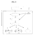
- a shape of a composite metal nanorod is generally cylindrical or generally cuboid can be determined based on that of the composite metal nanorod observed with a transmission electron microscope (TEM).
- TEM transmission electron microscope
- a shape of the composite metal nanorod is generally cylindrical (e.g., a composite metal nanorod whose end surface is spherical (indicated by C or E in FIG. 3 ), that whose end surface is ellipsoidal (indicated by D in FIG. 3 ), and that having an ellipsoidal shape (indicated by F in FIG. 3 )).
- a shape of the composite metal nanorod is generally cuboid (e.g., a composite metal nanorod whose end surface is polyhedral (indicated by A or B in FIG. 3 )).
- the length L of the flat portion of the end surface (cap) of the composite metal nanorod is identical to a below-described length L of a portion of an end surface of a composite metal nanorod, the portion being in contact with a perpendicular line to the major axis of the composite metal nanorod.
- both end surfaces of the composite metal nanorod are preferably rounded and have no corners from the viewpoint of attaining a sharp absorption peak width shown by the minor axis and improving dichroism property.
- the rounded shape of the end surfaces is not particularly limited and may be appropriately determined depending on the purpose. It is, for example, spherical, ellipsoidal and polyhedral. Specifically, as shown in FIGS. 4A to 4C , both end surfaces of a composite metal nanorod are rounded preferably so that the expression L ⁇ 0.9B is satisfied, more preferably so that the expression L ⁇ 0.8B is satisfied.
- absorption shown by the minor axis may undesirably be broad.
- the composite metal nanorod of the present invention is not particularly limited, so long as it contains at least two different metals.
- a core metal forming the core nanorod is different from a shell metal forming the shell.
- the core nanorod and the shell may individually contain two or more different metals.
- the shell metal is preferably baser than the core metal.
- the reduction potential of the shell metal is higher than that of the core metal.
- the reduction potentials of the aforementioned metals are described in " Kagaku Binran Kaitei 3 Han kiso Hen II' (Manual for Chemistry 3rd edition (revised), Basic II ).
- the shell metal is preferably baser than the core metal. Specifically, when the core metal is baser than the shell metal, the core metal is eluted during precipitation of the shell metal.
- Examples of the core metal include gold, platinum and palladium, with gold being particularly preferred.
- shell metal examples include silver, copper and aluminum, with silver being particularly preferred.
- the composite metal nanorod of the present invention is particularly preferably a gold core-silver shell nanorod whose core is made of gold and whose shell is made of silver.
- the ratio by volume of the shell to the core nanorod is preferably 0.1 to 130. From the viewpoint of improvement in oxidation resistance, it is more preferably 1 to 40.
- the volume ratio is smaller than 0.1, a core nanorod is not sufficiently covered with a shell metal, resulting in the shell metal may not sufficiently exhibit its optical characteristics.
- the volume ratio is greater than 130, the formed composite metal nanorod may be oxidized.
- V shell i.e., the volume of the shell
- V core i.e., the volume of core nanorod
- a and B have the same meanings as defined above; a denotes a major axis length of the core nanorod, which length is obtained by measuring a length of the longest straight line between both ends of the core nanorod; and b denotes a minor axis length of the core nanorod, which length is obtained by measuring a width of the thickest part of the core nanorod.
- a shape of a composite metal nanorod or core nanorod is generally cylindrical or generally cuboid can be determined similar to the above description in relation to the equivalent-volume-sphere radius.
- the aspect ratio of the core nanorod is an average value of aspect ratios of 200 samples which are randomly selected under a transmission electron microscope (TEM).
- the aspect ratio of the core nanorod is preferably 1.5 to 24.
- the aspect ratio is preferably 1.5 to 10.
- the aspect ratio is smaller than 1.5, the formed composite metal nanorod can be adjusted in absorption characteristics in a narrower range of the visible light region, which is disadvantageous.
- the aspect ratio is greater than 24, a shell of shell metal is required to be thick in order for the formed composite metal nanorod to absorb light of the visible light region. As a result, the volume of the formed particles becomes large, potentially resulting in a drop in optical transparency of the formed composite metal nanorod.
- the equivalent-volume-sphere radius (r) of the core nanorod is preferably 10 nm or smaller. In order for the formed composite metal nanorod to scatter light to a less extent and be improved in absorption characteristics, it is more preferably 8 nm or smaller. When the equivalent-volume-sphere radius (r) of the core nanorod is in excess of 10 nm, the formed composite metal nanorod scatters light to a considerable extent and thus, a dispersion thereof and a composition containing it may degrade in transparency.
- the equivalent-volume-sphere radius (r) of the core nanorod is a radius of a sphere whose volume is the same as that of the core nanorod, and is calculated similar to the equivalent-volume-sphere radius of the composite metal nanorod.
- the synthesis method of the metal nanorod is not particularly limited. Examples thereof include a chemical reduction method, electrochemical reduction method, photochemical reduction method, mesoporous alumina electroforming method, thermal reduction method, and ultrasonic reduction method. Among these, a chemical reduction method is particularly preferable from the viewpoint of productivity.
- the synthesis method of the composite metal nanorod include the after-mentioned seed crystal forming method, core nanorod forming step and shell forming step, and preferably include other steps as necessary.
- the seed crystal forming step is a step of forming seed crystals by subjecting to reduction reaction a solvent containing a first metal compound.
- the core nanorod forming step is a step of forming core nanorods by subjecting to reduction reaction a solvent containing seed crystals, a surfactant and a first metal compound.
- Examples of the first metal compound include metal salts, metal complexes and organic metal compounds.
- Examples of the metal contained in the first metal compound include gold, platinum and palladium, with gold being particularly preferred.
- the acid forming the metal salts may be an inorganic or organic acid.
- the inorganic acid is not particularly limited and may be suitably selected in accordance with the intended use.
- examples thereof include nitric acid, and hydrohalic acids, such as hydrochloric acid, hydrobromic acid and hydroiodic acid.
- the organic acid is not particularly limited and may be suitably selected in accordance with the intended use. Examples thereof include carboxylic acid and sulfonic acid.
- carboxylic acid examples include acetic acid, butyric acid, oxalic acid, stearic acid, behenic acid, lauric acid and benzoic acid.
- Examples of the sulfonic acid include methylsulfonic acid.
- metal salts examples include silver nitrate, chloroauric acid and chloroplatinic acid.
- the chelating agent used for forming the metal complexes is not particularly limited and may be suitably selected in accordance with the intended use. Examples thereof include acetylacetonate and EDTA. Alternatively, the above metal salts and a ligand may form the metal complexes. Examples of the ligand include imidazole, pyridine and phenylmethylsulfide.
- the metal compound encompasses acids of halogenated metal ion complexes (e.g., chloroauric acid and chloroplatinic acid) and alkali metal salts (e.g., sodium chloroaurate and sodium tetrachloropalladate).
- halogenated metal ion complexes e.g., chloroauric acid and chloroplatinic acid
- alkali metal salts e.g., sodium chloroaurate and sodium tetrachloropalladate
- the shell forming step is a step of forming a shell on the core nanorod by subjecting to reduction reaction a solvent containing the core nanorod, a second metal compound, a surfactant and a vinylpyrrolidone compound.
- Examples of the second metal compound include metal salts, metal complexes and organic metal compounds.
- Examples of the metal contained in the second metal compound include silver, copper and aluminum, and particularly preferred is silver.
- the metal salts, metal complexes and organic metal compounds used as the second metal compound are similar to those used as the first metal compound.
- the reduction reaction is performed by, for example, heating of the solvent, photoreduction, addition of a reducing agent, and chemical reduction. Particularly preferably, it is performed by adding a reducing agent to the solvent.
- Examples of the reducing agent include hydrogen gas, sodium borohydride, lithium borohydride, hydrazine, ascorbic acid, amines and thiols. Note that the chemical reduction may also be performed by electrolysis.
- the solvent is not particularly limited and may be suitably selected in accordance with the intended use.
- examples thereof include water; alcohol solvents such as methanol, ethanol, n-propanol, isopropanol, t-butyl alcohol, glycerin, ethylene glycol, triethylene glycol, ethylene glycol monomethyl ether, diethylene glycol dimethyl ether, propylene glycol, dipropylene glycol and 2-methyl-2,4-pentanediol; ketone solvents such as acetone, methyl ethyl ketone (MEK), methyl isobutyl ketone, cyclohexanone, cyclopentanone, 2-pyrrolidone and N-methyl-2-pyrrolidone; ester solvents such as ethyl acetate and butyl acetate; amide solvents such as dimethylformamide and dimethylacetamide; nitrile solvents such as acetonitrile; ether solvents such as die
- vinylpyrrolidone compound examples include polyvinylpyrrolidone (PVP) and 1-vinyl-2-pyrrolidone, with polyvinylpyrrolidone (PVP) being particularly preferred.
- the number of repeating units of pyrrolidone is preferably 85 or more, more preferably 300 to 12,000.
- the number of repeating units of pyrrolidone is less than 85, PVP cannot adsorb on specific crystal faces of metal particles and then may undesirably become spherical particles.
- the surfactant is not particularly limited and may be suitably selected in accordance with the intended use.
- examples thereof include cetyltrimethylammonium salts (e.g., cetyltrimethylammonium bromide (CTAB), cetyltrimethylammonium chloride (CTAC) and cetyltrimethylammonium hydroxide (CTAH)), octadecyltrimethylammonium salts, tetradecyltrimethylammonium salts, dodecyltrimethylammonium salts, decyltrimethylammonium salts, octyltrimethylammonium salts and hexyltrimethylammonium salts.
- cetyltrimethylammonium salts e.g., cetyltrimethylammonium bromide (CTAB), cetyltrimethylammonium chloride (CTAC) and cetyltrimethylammonium hydroxide (CTAH)
- CTAB cetyltrimethylammonium bromide
- Cationic surfactants such as quaternary ammonium salts (e.g., cetyltrimethylammonium bromide (CTAB)) have bacteriocidal property and thus, concern about adverce effects on the environment (e.g., toxicity to aquatic organisms) arises.
- CTAB therefore, must be recovered in the relevant step in powder form to reduce effects on the environment.
- aqueous gold nanorod solution containing CTAB is left to stand at 5°C for 12 hours, and the precipitated CTAB crystals are separated through filtration with a filter fabric (#200). Through this treatment, about 75% of CTAB can be recovered in a solid state. If recovered during the course of nanorod production, CTAB can be reused.
- the time required for purification with an ultrafiltration membrane can be shortened, leading to reduction in production cost and effects on the environment.
- the composite metal nanorod of the present invention may be covered with a dispersing agent, a dielectric material made of metal oxide (e.g., a silicon oxide, aluminum oxide, and titanium oxide), and polymer (e.g., polyvinylpyrrolidone and polystyrene).
- a dispersing agent e.g., a silicon oxide, aluminum oxide, and titanium oxide
- polymer e.g., polyvinylpyrrolidone and polystyrene
- Composite metal nanorod covered with such a dielectric material can be controlled in its absorption properties and can be provided with various properties such as thermal stability and oxidation resistance.
- the dispersing agent is not particularly limited, as long as it is a compound capable of preventing nanorods from aggregation through charge repulsion and/or stearic hindrance with being adsorbed thereon and of imparting water-solubility and/or oil solubility to nanorods, and may be suitably selected in accordance with the intended use.
- Examples of the compound capable of preventing nanorods from aggregation through charge repulsion include low-molecular-weight ionic compounds (e.g., quaternary ammonium compounds, sulfonic acid compounds, phosphoric acid compounds and carboxylic acid compounds), and high-molecular-weight ionic compounds. From them, a compound used can be selected in light of surface potential and/or pH conditions (acidity or basicity) of particles intended to be dispersed.
- low-molecular-weight ionic compounds e.g., quaternary ammonium compounds, sulfonic acid compounds, phosphoric acid compounds and carboxylic acid compounds
- high-molecular-weight ionic compounds e.g., quaternary ammonium compounds, sulfonic acid compounds, phosphoric acid compounds and carboxylic acid compounds
- a compound used can be selected in light of surface potential and/or pH conditions (acidity or basicity) of particles intended to be dispersed.
- the compound capable of preventing nanorods from aggregation through stearic hindrance may contain a group for adsorbing on the particle surface and a moiety for stearic hindrance.
- Preferred examples of the group include S-containing functional groups (e.g., thiol, disulfide and sulfoxide); P-containing functional groups (e.g., phosphoric acid and phosphine); O-containing functional groups (e.g., carbonyl, carboxyl, ether and hydroxyl); and N-containing functional groups (e.g., amine, amino, ammonium, nitro, hydroxylamine, azo and imine).
- S-containing functional groups e.g., thiol, disulfide and sulfoxide
- P-containing functional groups e.g., phosphoric acid and phosphine
- O-containing functional groups e.g., carbonyl, carboxyl, ether and hydroxyl
- N-containing functional groups e.g., amine, amino, ammonium, nitro, hydroxylamine, azo and imine.
- the compounds having any one of these groups include Lupazol (a polyethyleneimine-based compound) and Tamol (a sulfonic acid-based compound) (produced by BASF Co.); and a thiol-terminated polymer (product of Polymer Source Inc.) (e.g., a thiol-terminated polyethylene glycol and thiol-terminated polystyrene glycol).
- a thiol-terminated polymer product of Polymer Source Inc.
- preferred examples of the dispersing agent include DISPERBIK-180, DISPERBIK-184, DISPERBIK-190, DISPERBIK-192, DISPERBIK-2000, and DISPERBIK-2001 (produced by BYK-Chemie Co.). These may be used alone or in combination.
- a composite metal nanorod-containing composition of the present invention contains the composite metal nanorod of the present invention and a binder; and may contain other components as necessary.
- the binder is not particularly limited, as long as it is a thermoplastic resin having high optical transparency, and may be suitably selected in accordance with the intended use.
- examples thereof include polyvinyl acetal resins, polyvinyl alcohol resins, polyvinyl butyral resins, polymethyl methacrylate resins, polycarbonate resins, polyvinyl chloride resins, saturated polyester resins and polyurethane resins. These may be used alone or in combination.
- Examples of the other components include solvents, dispersants, and surfactants.
- the solvent is not particularly limited and may be suitably selected in accordance with the intended use.
- examples thereof include water; alcohol solvents such as methanol, ethanol, n-propanol, isopropanol, t-butyl alcohol, glycerin, ethylene glycol, triethylene glycol, ethylene glycol monomethyl ether, diethylene glycol dimethyl ether, propylene glycol, dipropylene glycol and 2-methyl-2,4-pentanediol; ketone solvents such as acetone, methyl ethyl ketone (MEK), methyl isobutyl ketone, cyclohexanone, cyclopentanone, 2-pyrrolidone and N-methyl-2-pyrrolidone; ester solvents such as ethyl acetate and butyl acetate; amide solvents such as dimethylformamide and dimethylacetamide; nitrile solvents such as acetonitrile; ether solvents such as die
- antioxidants examples include ascorbic acid, citric acid, polyvinyl alcohol resins and triazole compounds. These may be used alone or in combination.
- the composite metal nanorod-containing composition may additionally contain a crosslinking agent and/or plasticizer, in order to improve the quality of a film formed therefrom.
- a crosslinking agent such as boric acid
- a plasticizer such as glycerin
- the crosslinking agent and plasticizer may be incorporated during film formation. Alternatively, they may be applied through wet coating after film formation or film stretching.
- a dispersing agent adsorbed on the surfaces of composite metal nanorods may be appropriately substituted with another dispersing agent in consideration of compatibility to a solvent and binder used.
- the composition may be mixed with the composition so that the resultant composition has various properties such as UV and/or heat ray-absorbing property and has the same refractive index as glass.
- the composition may be provided with UV ray-absorbing property and/or heat ray-shielding property through addition of semiconductive metal oxide particles.
- thermoplastic resin is not particularly limited, as long as it is a polymer which is capable of dispersing the metal nanorods, has high transparency and is stretchable. From the viewpoint of stretchability and orientation properties of the metal nanorods, preferred are polyvinyl alcohol (PVA) resins.
- PVA polyvinyl alcohol
- the polyvinyl alcohol resin is commercially available in the form of a powder or pellet.
- KURARAY POVAL 105, 117, 124, 135, 205, 217, 224 and 235 produced by KURARAY Co., Ltd., and the like.
- the saponification degree of the polyvinyl alcohol resin is preferably 80 mole% to 100 mole%. It is more preferably 85 mole% to 100 mole% from the viewpoint of the orientation properties and optical properties.
- the polyvinyl alcohol resin may be modified.
- polyvinyl formals and polyvinyl acetals which are individually modified with polyvinyl butyral or aldehydes are exemplified.
- the polymerization degree of the polyvinyl alcohol resin is preferably 300 to 10,000. It is more preferably 500 to 4,000 from the viewpoint of the coating applicability and stretchability.
- the polyvinyl alcohol resin can be used as a polyvinyl alcohol resin solution after being dissolved in an appropriate solvent.
- the solvent is not particularly limited, and examples thereof include water, diemthylsulfoxide, N-methylpyrrolidone, and glycols, with water being preferred in terms of the solubility and dryness after the coating of the polyvinyl alcohol resin solution.
- a proper organic solvent may be mixed therewith.
- the organic solvent to be mixed with water include alcohols such as ethanol, n-propanol, isopropanol, butanol and methanol; alcohol-based solvents such as glycerine, ethylene glycol, triethylene glycol, ethylene glycol monomethylether, diethylene glycol dimethylether, propylene glycol, and dipropylene glycol; ketone-based solvents such as acetone, 2-pyrrolidone, and N-methyl-2-pyrrolidone; amide-based solvents such as dimethylformamide, and dimethylacetoamide; ether-based solvents such as tetrahydrofuran, and dioxane; and acetonitrile. These solvents may be used alone or in combination.
- the concentration of the polyvinyl alcohol resin in the polyvinyl alcohol resin solution is preferably 0.1% by mass to 20% by mass. It is more preferably 0.5% by mass to 10% by mass from the viewpoint of the coating applicability and formability of a thin layer.
- the polyvinyl alcohol resin solution may contain, besides the metal nanorods being dichroic material, a surfactant, hardener, plasticizer, dispersant, antioxidant, corrosion inhibitor, ultraviolet absorber, heat ray blocking agent, anti-wetting agent, thermal stabilizer, dye, pigment, metal oxide, metal nitride, conductive particles, and the like.
- the surfactant is incorporated into the polyvinyl alcohol resin solution for enhancing the coating applicability, is not particularly limited and may be suitably selected in accordance with the intended use. Examples thereof include nonionic surfactants, cationic surfactants, anionic surfactants and amphoteric surfactants.
- nonionic surfactants examples include polyoxyethylene alkyl ethers, polyoxyethylene alkyl phenol ethers, alkyl glucoxides, polyoxyethylene fatty acid esters, sucrose fatty acid esters, sorbitan fatty acid esters, polyoxyethylene sorbitan fatty acid esters and fatty acid alkanolamides.
- cationic surfactants examples include alkyltrimethyl ammonium salts, dialkyldimethyl ammonium salts, alkyldimethylbenzyl ammonium salts and amine salts.
- anionic surfactants examples include soaps (fatty acid sodium/potassium salts), alkylbenzenesulfonic acid salts, higher alcohol sulfuric acid ether salts, polyoxyethylene alkyl ether sulfuric acid salts, ⁇ -sulfo fatty acid esters, ⁇ -olefin sulfonic acid salts, monoalkyl phosphoric acid ester salts and alkane sulfonic acid salts.
- amphoteric surfactants examples include alkylamino fatty acid salts, alkylbetaines and alkyl amine oxides. These may be used alone or in combination.
- the hardener is incorporated into the polyvinyl alcohol resin solution for improving the quality of the resultant film.
- Materials thereof are not particularly limited, and a boric acid, diphenylboric acid are exemplified.
- the plasticizer is incorporated into the polyvinyl alcohol resin solution for imparting the flexibility of the resultant film.
- Materials thereof are not particularly limited, and various low-molecular glycols and high-molecular glycols are exemplified.
- the hardener and plasticizer may be incorporated into the polyvinyl alcohol resin solution.
- they may be applied thereonto by wet coating.
- antioxidants examples include ascorbic acids, citric acids, and triazole compounds. These may be used alone or in combination.
- Coating layers to be formed on the thermoplastic resin substrate may be only a single layer of a metal nanorod-containing polyvinyl alcohol resin layer. Further, functional films containing metal nanorods, a ultraviolet absorber, heat ray-blocking agent, anti-wetting agent, thermal stabilizer, dye, pigment, metal oxide, metal nitride, conductive particles, etc. may be stacked on the polyvinyl alcohol resin layer.
- thermoplastic resin substrate before the PVA layer is applied onto the thermoplastic resin substrate, or alternatively may be stacked on the PVA layer, or may be formed after film stretching. (the method for producing a polarizing film)
- the method for producing a polarizing film of the present invention includes at least a composition layer forming step, and a stretching step.
- the composition layer forming step is a step of forming a composition layer containing at least dichroic anisotropic metal nanoparticles and a thermoplastic resin on a stretchable substrate.
- the forming method of the composition layer is not particularly limited and may be suitably selected in accordance with the intended use.
- the composition layer is preferably formed by, for example, a method in which a composition liquid containing at least dichroic anisotropic metal nanoparticles and a thermoplastic resin is applied onto a stretchable substrate and then dried.
- a composition liquid is prepared in which at least the dichroic anisotropic metal nanoparticles and the thermoplastic resin are dissolved and/or dispersed.
- the solvent is not particularly limited and may be suitably selected in accordance with the intended use.
- examples thereof include water; alcohol solvents such as methanol, ethanol, n-propanol, isopropanol, t-butyl alcohol, glycerin, ethylene glycol, triethylene glycol, ethylene glycol monomethyl ether, diethylene glycol dimethyl ether, propylene glycol, dipropylene glycol and 2-methyl-2,4-pentanediol; ketone solvents such as acetone, methyl ethyl ketone (MEK), methyl isobutyl ketone, cyclohexanone, cyclopentanone, 2-pyrrolidone and N-methyl-2-pyrrolidone; ester solvents such as ethyl acetate and butyl acetate; amide solvents such as dimethylformamide and dimethylacetamide; nitrile solvents such as acetonitrile; ether solvents such as die
- composition liquid is applied onto the stretchable substrate.
- the coating method is not particularly limited, and a common coating method may be employed. Examples of thereof include wet a coating method, bar coating method, wire coating method, roll coating method, gravure coating method, spray coating method, dye coating method, dip coating method, and spin-coating method.
- Conditions for the drying after the coating of the composition liquid are not particularly limited, as long as the applied coating liquid is dried at a temperature at which the stretchable substrate is not deformed, and the coating liquid is preferably dried at 100°C or lower.
- the drying was performed in the following manner.
- a stretchable substrate whose surface was coated with the composition liquid was placed in a clean oven, with the stretchable substrate being attached on a stainless steel plate, followed by heating at 60°C for 15 minutes.
- the stretchable substrate with the composition layer formed on a surface thereof when wound, it may be wound together with a cover film to prevent blocking.
- the cover film is not particularly limited and may be the same film as used for the stretchable substrate.
- a polyolefin resin film and a polyester resin film are exemplified.
- a film made of polypropylene, polyethylene, polyethylene terephthalate or the like is preferred.
- the thickness of the cover film is preferably 1 ⁇ m to 1,000 ⁇ m, more preferably 3 ⁇ m to 50 ⁇ m.
- the upper limit of thickness of the dried composition layer is not particularly limited, as long as it is 25 ⁇ m or less. It is however preferably 15 ⁇ m or less, particularly preferably 10 ⁇ m or less.
- the lower limit of thickness of the dried composition layer is not particularly limited and may be suitably selected in accordance with the intended use. It is however preferably 0.16 ⁇ m or more.
- dichroic anisotropic metal nanoparticles in the coating layer are excessively proximate to each other, possibly resulting in a change of absorption characteristics of the dichroic anisotropic metal nanoparticles and/or breakage of the composition layer into pieces.
- the thickness is more than 25 ⁇ m, the orientation properties of the dichroic anisotropic metal nanoparticles may degrade.
- the stretchable substrate is not particularly limited, as long as it can be stretched. It is however particularly preferably the thermoplastic resin mentioned above, or a stretchable material that can be stretched at a temperature of 150°C or lower at which the dichroic anisotropic metal nanoparticles do not degrade.
- the stretchable substrate examples include a polyester resin film, polyolefine resin film, nylon resin film, polyvinyl chloride resin film and polycarbonate resin film.
- polyester resin film an amorphous polyethylene terephthalate film and a polyethylene terephthalate film, etc. are exemplified.
- polyolefin resin film a polyethylene film, a polypropylene film, etc. are exemplified.
- unstretched film from the viewpoint of the stretchability, and more preferred is an unstretched polyethylene terephthalate film from the view point of the capability of being stretched to 6 times or more at 150°C or lower.
- the unstretched polyethylene terephthalate film examples include PETMAX (film thickness: 300 ⁇ m, provided with antistatic coating on one surface side, produced by TOYOBO Co., Ltd.).
- the glass transition temperature of the stretchable substrate is not particularly limited. It is however preferably 150°C or lower.
- the thickness of the stretchable substrate is preferably 10 ⁇ m to 1,000 ⁇ m, more preferably 100 ⁇ m to 700 ⁇ m, from the viewpoint of handleability in coating and film stretching.
- the stretchable substrate should be provided with characteristics described below. That is, the stretchable substrate has a contact angle at which a metal nanorods-dispersed layer forming a polarizing film can be formed; the composition layer will not be peeled off from the stretchable substrate in the stretching step; and when a resulting polarizing film is to be stacked on another base material, the stretchable substrate can be peeled off from the polarizing film after being stretched with the polarizing film.
- the stretchable substrate it is also possible to use the one that has been subjected to a surface treatment for improve the coating applicability of the composition liquid and to an antistatic treatment for reducing the peeling charge that could be caused when the polarizing film is peeled off.
- Examples of the surface treatment for improving the coating applicability of the composition liquid include a corona treatment, flame treatment, plasma treatment, UV ozone treatment, and primer treatment.
- a primer resin such as a polyurethane resin, and a polyester resin, can be used.
- the stretchable substrate is provided with metal oxide particles such as ITO, and ATO; a deposition film; a conductive material such as metal nanoparticles, and nanowires; and an antistatic agent such as quaternary ammonium salt.
- These surface treatments may be provided on one surface or both surfaces of the stretchable substrate, depending on the purpose, or may be further provided inside the stretchable substrate for the sake of imparting intended performance capabilities.
- the stretching step is a step of stretching the composition layer together with the stretchable substrate to form a polarizing film on the stretchable substrate.
- Equation (1) a relationship between t and d is represented by the following Equation (1) (where t denotes a thickness of the polarizing film, and d denotes a thickness of the composition layer).
- T MD denotes a draw ratio of the polarizing film in a uniaxially longitudinally stretched direction
- T TD denotes a shrinkage ratio of the polarizing film in a direction perpendicular to the stretched direction.
- Equation (1) for example, when T TD is equal to 0.5 times, T MD is equal to 4 times, and the thickness d of the composition layer is 1 ⁇ m to 25 ⁇ m, the thickness t of the stretched polarizing film is calculated as being 0.5 ⁇ m to 12.5 ⁇ m.
- the stretchable substrate with the composition layer applied on a surface thereof (abbreviated to "laminated film”) is subjected to stretching.
- the stretching direction is not particularly limited, as long as the laminated film can be stretched.
- roll-uniaxial-longitudinal stretching, and tenter stretching are exemplified.
- the roll-uniaxial-longitudinal stretching method is not particularly limited, and examples thereof include a method in which an object is uniaxially longitudinally stretched between rolls having different circumferential speed; and a method of uniaxially stretching an object so as to be roll-pressed against a heat roll.
- tenter stretching is preferable.
- a laminated film in general, can be uniaxially laterally stretched in a direction perpendicular to the direction which the laminated film is conveyed, however, the laminated film is relaxed or shrunk in parallel with the direction of the laminated film being conveyed by providing a relaxing process before or after the uniaxial-lateral stretching, or simultaneously to the uniaxial-lateral stretching, and thereby the orientation properties can be improved.
- the relaxing process is a process in which the laminate film is shrunk. For example, a tension applied to a laminated film is relaxed or the zone temperature of the relaxing process is increased.
- a preheating step, a relaxing step, a heat fixing step, and a cooling step may be incorporated before or after the stretching step.
- the draw ratio is not particularly limited and may be suitably selected in accordance with the intended use.
- the draw ratio is preferably 1.5 times to 8 times.
- uniaxial-lateral stretching is employed, it is preferably 1.5 times to 8 times.
- a polarizing film stretched in the draw ratio range can exhibit excellent polarizability without causing breakage.
- the drawing temperature is not particularly limited. It is however preferably around a glass transition temperature of the stretchable substrate and the PVA contained in the composition layer.
- the drawing temperature is preferably 60°C to 150°C, more preferably 80°C to 120°C. Within the drawing temperature range, it is possible to obtain excellent stretchability and to prevent the stretchable substrate and the composition layer (PVA) from degrading.
- the stretching process may be performed under nitrogen atmosphere.
- the polarizing plate of the present invention includes the polarizing film described above.
- the embodiment of the polarizing plate is not particularly limited provided that it has the polarizing film, and may be suitably selected in accordance with the intended use. However, in a preferred embodiment of the polarizing plate, a base material is provided respectively on one surface of the polarizing film and an opposite surface thereof.
- the polarizing film may be used as a laminate film in a state of being provided with the stretchable substrate, however, it is preferred that the polarizing film be laminated on a base material before being used, because a stretched thermoplastic resin substrate has a strong curling tendency and a high birefringence.
- the polarizing can be laminated on a protective film such as a polyvinyl butyral (PVB) film and a triacetylcellulose (TAC) film which are capable of bonding glass; a glass which is a transparent base material; a substrate or a molded product, each of which is formed of a polycarbonate resin, an acrylic resin or the like.
- a protective film such as a polyvinyl butyral (PVB) film and a triacetylcellulose (TAC) film which are capable of bonding glass
- a glass which is a transparent base material
- a substrate or a molded product each of which is formed of a polycarbonate resin, an acrylic resin or the like.
- the embodiment of the polarizing plate mentioned above is not particularly limited, and there may be exemplified by a first embodiment and a second embodiment described below.
- the first embodiment of the polarizing plate is configured such that a first base material and a second base material are provided in this order, respectively, on one surface of the polarizing film and an opposite surface thereof.
- the first base material is not particularly limited and may be suitably selected in accordance with the intended use.
- examples thereof include, but not limited to, a polyvinyl butyral resin (PVB) film, and an ethylene-vinyl copolymer resin (EVA) film. These materials are commercially available.
- PVB polyvinyl butyral resin
- EVA ethylene-vinyl copolymer resin
- S-LEC produced by Sekisui Chemical Co. Ltd.
- SAFLEXAR-11 produced by SORCIA Japan Co. Ltd.
- RB-41 produced by SORCIA Japan Co. Ltd.
- ethylene-vinyl copolymer resin film S-LEC EN (produced by Sekisui Chemical Co. Ltd.), and SAFLEX (produced by SORCIA Japan Co. Ltd.) may be used, for example.
- the second base material is not particularly limited may be suitably selected in accordance with the intended use. There may be exemplified by glass, a substrate or a molded product, each of which is formed of a polycarbonate resin, an acrylic resin or the like.
- the thickness of the first base material is not particularly limited, however, it is preferably 100 ⁇ m to 1,000 ⁇ m.
- the first base material may contain a plasticizer, ultraviolet ray absorber, heat ray-blocking agent, pigment, etc., as necessary.
- the first base material may also be configured to incorporate the same composition as that of an intermediate layer used in the after-mentioned antiglare vehicular window.
- the second base material may also be configured to incorporate the same composition as that of a glass base material used in the after-mentioned antiglare vehicular window.
- FIG. 6F A configuration example of a polarizing plate 150 (250) according to the first embodiment is shown in FIG. 6F ( FIG. 7D ).
- a polarizing film 13 (23) is configured such that a first base material 14a, 14b (28a, 28b) and a second base material 15a, 15b (25a, 25b) are provided in this order, respectively, on one surface of the polarizing film 13 (23) and an opposite surface thereof via an adhesive layer 16.
- the second embodiment of the polarizing plate is configured such that a base material is provided respectively on one surface of the polarizing film and an opposite surface thereof, and the base material is one of a protective film and a transparent base material.
- the protective film is not particularly limited and may be suitably selected in accordance with the intended use.
- examples thereof include, but not limited to, cellulose acetate resin films such as a triacetylcellulose film, and a diacetylcellulose film; acrylic resin films; polycarbonate resin films; polyolefin resin films such as a polyethylene film, and a polypropylene film; cyclic polyolefin resins films such as a polyester resin film, and a polynorbornene resin film; polyethylene naphthalate resin films polyimide resin films; polyamide resin films; nylon resin films; and fluororesin films.
- triacetylcellulose films produced by Fujifilm Holdings Corporation
- cyclic polyolefine resin films such as ZEONOR and ZEONEX (produced by Nippon Zeon Corp.), ARTON (produced by JSR Corporation).
- the thickness of the protective film is preferably 30 ⁇ m to 300 ⁇ m, more preferably 50 ⁇ m to 200 ⁇ m.
- the transparent base material is not particularly limited and may be suitably selected in accordance with the intended use.
- These base materials may be flat or curved.
- FIG. 6E A configuration example of a polarizing plate 150 (200) according to the second embodiment is shown in FIG. 6E ( FIG. 7C ).
- a polarizing film 13 (23) is configured such that a first base material 14a, 14b (28a, 28b) is provided respectively on one surface of the polarizing film 13 (23) and an opposite surface thereof.
- the method for producing a polarizing plate of the present invention includes at least a polarizing film laminating step, and a laminate forming step, and includes other steps as necessary.
- a base material is laminated on one surface of a polarizing film, the polarizing film being produced by the method for producing a polarizing film of the present invention, the one surface opposing a surface provided with a stretchable substrate, and the stretchable substrate is peeled off from the surface having been provided with the stretchable substrate.
- stretchable substrate it is possible to use a stretchable substrate for use in the method for producing a polarizing film of the present invention.
- the base material In lamination/attachment of the base material on the polarizing film, when the adhesion between the polarizing film and the base material is sufficient, they are bonded to each other by pressure contact using a laminator or a calender, or heat lamination using a heat laminator. When the adhesion therebetween is insufficient, the base material can be laminated on and bonded to the polarizing film via an adhesive, a pressure-sensitive adhesive, or an adhesive sheet. When the adhesive and the adhesive sheet is used, an adhesive which is optically isotropic and transparent in the visible light region is used.
- an adhesive sheet such as PANACLEAN PD-S1 (produced by Panack Co., Ltd.) is used.
- the same base material as used as the first base material and the second base material in the polarizing plate can be used.
- the method of peeling off the stretchable substrate from the polarizing film is not particularly limited, and it the stretchable substrate can be peeled off therefrom using a winder or the like. On this occasion, when the stretchable substrate is rolled up with a winder under charge conditions, charge may be removed by an ionic air generator, etc.
- the base material is further provided on the surface of the polarizing film opposing the surface having been provided with the base material, so as to form a laminate in which the base material is provided on both the surfaces of the polarizing film.
- the same method as used in the polarizing film laminating step can be employed.
- the other steps are not particularly limited and may be suitably selected in accordance with the intended use. Examples thereof include a combining step.
- the laminate is combined with or sandwiched by a further base material, from one surface of the laminate and the other surface opposing the one surface.
- the further base material is not particularly limited, however, glass, and a substrate or a molded product formed of a polycarbonate resin or an acrylic resin are preferred, with glass being more preferred.
- the glass may be configured to incorporate the same composition as that of a glass base material used in the after-mentioned antiglare vehicular window.
- the method of combining the laminate with the base material is not particularly limited and may be suitably selected in accordance with the intended use.
- known methods for producing a laminated glass are exemplified.
- the combining step can be carried out as a production process of a polarizing plate in the form where a laminate produced by sandwiching a polarizing film between two sheets of the first base material is combined with the second base material.
- the method of providing a polarizing film on the first base material is not particularly limited.
- a hat lamination method, a calendering method, and an attaching method using the above-mentioned adhesive or adhesive sheet are exemplified.
- the polarizing film can be attached to the first base material by a heat laminator equipped with a heat roller.
- a solution containing a binder compatible with both of the base material and the polarizing film may be used as an adhesive.
- the base material is a polyvinyl butyral film (PVB film)
- PVB film polyvinyl butyral film
- an isopropanol solution containing polyvinyl butyral is applied onto the PVB film, the polarizing film is attached to the PVB film, dried, and then the stretchable substrate is peeled off therefrom.
- the polyvinyl butyral solution used as an adhesive may contain a plasticizer, a ultraviolet absorber, an antioxidant, and an infrared ray-blocking agent, and the like.
- a solvent contained in the polyvinyl butyral solution used as an adhesive preferred is a solvent that dissolves the PVB film but does not dissolve the polarizing film.
- solvents examples include isopropanol, toluene, acetone, and methylethylketone. These solvents may be sued alone or in combination.
- optically functional layers such as an anti-reflection layer, a hard coat layer, an antiglare layer, and antiglare-hard coat layer, and a surface-treated layer whose surface has been subjected to hydrophilic treatment or water repellent treatment may be provided.
- the provision of these functional layers may be provided on the base material may be before attaching of the polarizing film to the base material or after the attaching.
- the polarizing film is produced by the method for producing a polarizing film.
- a composition containing dichroic anisotropic metal nanoparticles 10 is applied onto a stretchable substrate 12 and dried to form a composition layer 11 (refer to FIG. 6A ), and the stretchable substrate 12 with the composition layer 11 formed on a surface thereof is stretched together with the composition layer 11, and thereby a polarizing film 13 is obtained on the stretchable substrate 12 (refer to FIG. 6B ).
- the laminate film 17 is attached to a first base material 14a via an adhesive layer (an adhesive sheet) 16 so that the surface of the laminate film 17 not provided with the stretchable substrate 12 faces the first base material 14a (refer to ( FIG. 6C ).
- the stretchable substrate 12 is peeled off from the laminate film 17, and further, the first base material 14a is laminated to the polarizing film 13 (refer to FIG. 6D ).
- a first base material 14b is laminated on a surface of the polarizing film 13 from which the stretchable substrate 12 has been peeled off, and then the first base material 14a, 14b are fixed on both surfaces of the polarizing film 13 ( FIG. 6E ).
- the fixing of the first base material 14a, 14b on the both surface of the polarizing film 13 may be performed sequentially or at a time.
- a separator film e.g., polypropylene film
- a polarizing plate 100 in the form of a laminate in which the polarizing film 13 is sandwiched by the first base material 14a and 14b.
- a polarizing plate e.g., laminated glass
- the first base material 14a, 14b are used as intermediate films and combined with the second base material 15a, 15b
- it can be produced by a known production method of a laminated glass (refer to FIG. 6F ).
- the polarizing plate 100 is combined with base material (glass plates) 15a, 15b, from both surface sides of the polarizing plate 100, preliminarily pressed by heat lamination etc., and then heated in an autoclave at a 150°C for 30 minutes, thereby making it possible to produce a polarizing plate (laminated glass) 150 according to an aspect where the polarizing plate 100 is combined with base material (glass plates) 15a and 15b (refer to FIG. 6F ).
- a polarizing plate is produced without using an adhesive layer (an adhesive sheet layer).
- a laminate film 27 is produced in which a polarizing film 23 containing dichroic anisotropic metal nanoparticles 20 on a stretchable substrate 22.
- the laminate film 27 is directly attached to a first base material 28a so that the surface of the laminate film 27 not provided with the stretchable substrate 22 faces the first base material 28a (refer to FIG. 7A ).
- the stretchable substrate 22 is peeled off from the laminate film 27, and the first base material 28a is laminated on the polarizing film 23 (refer to FIG. 7B ).
- a first base material 28b is laminated on the surface of the polarizing film 23 from which the stretchable substrate 22 has been peeled off, and then the first base material 28a, 28b are fixed on both surfaces of the polarizing film 23 ( FIG. 7C ).
- the fixing of the first base material 28a, 28b on the both surface of the polarizing film 23 may be performed sequentially or at a time.
- a polarizing plate 200 in the form of a laminate in which the polarizing film 23 is sandwiched by the first base material 28a, 28b.
- the polarizing plate may be produced as a polarizing plate (e.g., laminated glass) 250, in which a base material 28a, 28b are used as intermediate films and combined with two sheets of another base material 25a, 25b (refer to FIG. 7D ), in the same manner as in the first embodiment in which an adhesive layer (an adhesive sheet layer) is used.
- a polarizing plate e.g., laminated glass 250
- a base material 28a, 28b are used as intermediate films and combined with two sheets of another base material 25a, 25b (refer to FIG. 7D )
- the first base material 28a an intermediate film
- a laminate film 27 are combined in this order, subsequently, the stretchable substrate 22 is peeled off from the laminate film 27, and the first base material 28b (the intermediate film) and the second base material 25b (a substrate made of glass, etc.) are further stacked in this order on the surface of the laminate film 27 from which the stretchable substrate 22 has been peeled off, and combined together, thereby the polarizing plate (laminated glass) 250 may be produced.
- a laminate (100) in the form of the polarizing film 13 which is provided, on both surfaces, with the first base material 28a, 28b is laminated, with being sandwiched by the second base material 25a, 25b, and combined together, thereby the polarizing plate (laminated glass) 250 may be produced.
- the combining step using the second base material is not necessarily required.
- the first base material is, for example, the protective film such as a TAC film or a transparent base such as glass plate
- the polarizing plate can be produced as the polarizing plate 100 (third embodiment) shown in FIG. 6E in the first embodiment or the polarizing plate 200 (fourth embodiment) shown in FIG. 7C in the second embodiment.
- the same type of base materials are not necessarily provided on respective surfaces of the polarizing film in the first to fourth embodiments, base materials may be selected depending on the purpose, to be provided on the polarizing film.
- the polarizing plate may be configured to further provide the surface treatment layer such as a reflection preventing layer.
- FIG. 8 shows a polarizing plate 300 having a layer configuration in which a reflection preventing layer 39/a glass substrate 35/an adhesive sheet 36/a polarizing film 33/an adhesive sheet 36/and a TAC film 38 are provided in this order.
- the polarizing plate 300 can be produced by providing, on a surface of the glass substrate 35, the reflection preventing layer 39, and providing, on another surface of the glass substrate 35, the adhesive sheet 36, the polarizing film 33, the adhesive sheet 36 and the TAC film 38.
- the glass substrate 35 provided with the reflection preventing layer 39 can be attached together by passing through a laminator.
- the reflection preventing layer can also be provided on a protective film such as a TAC film.
- a protective film such as a TAC film.
- FIG. 9 A polarizing plate 350 shown in FIG. 9 has a layer configuration in which a glass substrate 35/an adhesive layer 36/a polarizing film 33/an adhesive sheet 36/a TAC film 38/and a reflection preventing layer 39 are provided in this order.
- the antiglare vehicular window of the present invention includes the polarizing film of the present invention and further includes other layers as necessary.
- the antiglare vehicular window preferably includes, as the other layers, an anti-reffection film.
- polarizing film As the polarizing film, a polarizing film according to the present invention is used.
- the polarizing film is preferably provided on the base material side of the inside surface of a vehicle (the surface side of a vehicle on which outside light is not incident).
- an angle of the base material surface with respect to a horizontal reference plane be 20° to 50°, and when viewed by a driver in the vehicle, the direction of the average of absorption axes of anisotropic absorber in the polarizing film be oriented at an angle of less than ⁇ 30° with respect to an intersection between the base material surface and the horizontal reference plane.
- the antiglare vehicular window is preferably formed on a surface (back surface) of a base material constituting the front glass (windshield) of the vehicle, opposite to the light incident side surface, as shown in FIG. 10 .
- a laminated glass formed in a unit structure which includes an intermediate layer between two plate glasses and a reflection preventing layer 59 it is preferred that the polarizing film 53 be formed as an intermediate layer, as shown in FIG. 11 , or the polarizing film 53 be formed on a surface (back surface) of the laminated glass opposite to the light incident side surface as shown in FIG. 12 .
- an angle of the surface of a windshield in a vehicle with respect to the surface of a dashboard 5 is preferably 20° to 50°, more preferably 25° to 40°, as shown in FIG. 10 .
- the vehicle is not particularly limited, as long as an angle of the surface of the windshield with respect to the horizontal reference plane of a dashboard is in the range of 20° to 50°, and may be suitably selected in accordance with the intended use.
- Examples of the vehicle include automobiles, buses, auto-trucks, electric trains, super express trains, airplanes, passenger planes and vessels.
- these vehicles particularly preferred are automobiles.
- a front glass (windshield) 55 (55a, 55b) is commonly provided at an angle of approximately 30° with respect to the horizontal reference plane.
- a shadow of the dashboard 5, which obstructs the view of the driver in the vehicle is a light reflected to an inner surface of the windshield 55 at an incident angle of approximately 60°.
- a polarizing film 53 which contains dichroic anisotropic metal nanoparticles 50 and has an anisotropic absorber,P which is oriented substantially in a horizontal direction to the horizontal plane of the glass, is assumed to have a transmittance of 75%, it is conceivable that sun light I o is divided into a horizontal polarization component Te 0 and a vertical polarization component Tmo.
- a vertical component aiTmo of the light I 2 has an incident angle which is substantially Brewster angle to the surface of the windshield, the vertical component aiTm 0 passes straight an optical path of I 3 and I 7 to be emitted outside.
- a Brewster angle is an incident angle where light reflected at an interface of substances having different refractive indexes is completely polarized.
- a horizontal component (a/2)Te of the light I 2 is reflected at approximately 3% by an antireflective film, which is the outermost surface of the back surface of the windshield, and the reflected light component enters into the drive's eyes. Also, remaining 97% of the horizontal component (a/2)Te enters inside the windshield, one-half of the horizontal component is emitted outside, and the remaining half of the horizontal component is reflected toward the inside of the vehicle to be I 4 , which is then absorbed by the anisotropic absorber P and further reduced to one half to become light I 5 . As a result, the light I 5 will enter into the driver's eyes.
- the light intensity I h of the shadow of the dashboard is 1.36%, and has a light intensity reduced by an approximately single-digit number or more, as compared to the light intensity 32% in the case where a glass is used.
- glass As a base material for use in the antiglare vehicular window of the present invention, glass is the most suitable. This is because glass has 12-year durability which is the roughly-estimated operating life of vehicles under environments where they are exposed to wind and rain, and do not disturb the polarization. However, recently, plastics, which have high-durability and high-isotropy and are rarely disturb polarization, for example norbornene polymers, are provided even in polymer plate products. Materials other than glass can be also used for the base material.
- the glass base material is not particularly limited and may be suitably selected in accordance with the intended use, and for example, single-layer glass, laminated glass, reinforced laminated glass, multilayered glass, reinforced multilayered glass, laminated multilayered glass are exemplified.
- a plate glass constituting the above-mentioned glass, for example, transparent plate glass, template glass, wire glass, line wire glass, reinforced plate glass, heat ray-reflecting plate glass, heat ray-absorbing plate glass, Low-E plate glass, and other various plate glasses.
- the glass base material may be a colorless transparent glass or a colored transparent glass, as long as it is a transparent glass.
- the thickness of the glass base material is not particularly limited and may be suitably selected in accordance with the intended use. It is however preferably 2 mm to 20 mm, more preferably 4 mm to 10 mm.
- a laminated glass is what has two sheets of plate glass, and an intermediate layer which is interpositioned between the two sheets of plate glass so as to be integrated in one body.
- Such a laminated glass is safe because shards of glass will not be scattered even upon receiving an impact from an external source, it is widely used as windshields of vehicles such as automobiles, and as windowpanes of buildings and plants, etc.
- laminated glasses having an extremely thin thickness are used to achieve the weight reduction, the thickness of one sheet of glass is 1 mm to 3 mm, and two sheets of glass are combined with an adhesive layer having a thickness of 0.3 mm to 1 mm to thereby form a laminated glass having a total thickness of approximately 3 mm to 6 mm.
- thermoplastic resin As a base material used in the intermediate layer, a thermoplastic resin is preferable.
- the thermoplastic resin include, but not limited to, polyvinyl acetal resins, polyvinyl alcohol resins, polyvinyl chloride resins, saturated polyester resins, polyurethane resins, ethylene-vinyl acetate copolymers.
- polyvinyl acetal resins particularly preferred are polyvinyl acetal resins in that an intermediate layer which is well balanced in various capabilities such as transparency, weatherability, strength, adhesive strength and the like.
- the polyvinyl acetal resin is not particularly limited and may be suitably selected in accordance with the intended use.
- examples thereof are polyvinyl alcohol resins obtained by reacting polyvinyl alcohol (hereinbelow, abbreviated to "PVA") with formaldehyde; narrowly-defined polyvinyl acetal resins obtained by reacting PVA with acetaldehyde; and polyvinyl butyral resins obtained by reacting PVA and n-butylaldehyde.
- the PVA used in synthesis of the polyvinyl acetal resin is not particularly limited and may be suitably selected in accordance with the intended use. However, those having an average polymerization degree of 200 to 5,000 are preferred, and those having an average polymerization degree of 500 to 3,000 are more preferred. When the average polymerization degree is less than 200, the strength of an intermediate layer formed using the resulting polyvinyl acetal resin may be excessively weakened. When it is more than 5,000, defects may occur during formation of the resulting polyvinyl acetal resin.
- the polyvinyl acetal resin is not particularly limited and may be suitably selected in accordance with the intended use.
- a polyvinyl acetal resin with a degree of acetalization of 40 mole% to 85 mole% is preferred, and a polyvinyl acetal resin with a degree of acetalization of 50 mole% to 75 mole% is more preferred.
- a polyvinyl acetal resin with a degree of acetalization less than 40 mole% or more than 85 mole% is used, it may be difficult to synthesize it because of its reaction mechanism.
- the degree of acetalization can be measured in accordance with JIS K6728.
- thermoplastic resin besides the thermoplastic resin, a plasticizer, a pigment, an adhesion adjustor, a coupling agent, a surfactant, an antioxidant, a thermal stabilizer, a light stabilizer, a ultraviolet ray absorber, an infrared ray absorber, etc. may be added.
- the forming method of the intermediate layer is not particularly limited and may be suitably selected in accordance with the intended use.
- a method is exemplified, in which a composition containing a thermoplastic resin and other components is uniformly kneaded, and the kneaded product is formed into a sheet by a conventionally known method such as extrusion method, calendering method, press method, casting method, and inflation method.
- the thickness of the intermediate layer is not particularly limited and may be suitably adjusted in accordance with the intended use. It is however preferably 0.3 mm to 1.6 mm.
- the intermediate layer is preferably the polarizing film of the present invention in terms of productivity, durability and the like.
- the intermediate layer is a laminate which includes the polarizing film, it is the same as above except that the intermediate layer contains anisotropic absorber, and the anisotropic absorber is made oriented in a substantially horizontal direction. Note that it is also possible to provide the polarizing film on one surface side of a laminated glass.
- the method for producing the laminated glass is not particularly limited and may be suitably selected in accordance with the intended use.
- an intermediate film is sandwiched in between two sheets of transparent glass plates, and the laminated-glass structural body thus prepared is put, for example, into a vacuum bag like a rubber bag, the vacuum bag is connected to an exhaust ventilation system, subjected to pre-bonding at a temperature of approximately 70°C to 110°C while sucking under reduced pressure (deaerating) so that the pressure inside the vacuum bag is a degree of pressure reduction of approximately -65 kPa to -100 kPa, and then the pre-bonded laminated-glass structural body is placed in an autoclave, followed by heating and pressurizing under the conditions of a temperature of 120°C to 150°C and a pressure of 0.98 MPa to 1.47 MPa to be completely bonded, thereby obtaining a desired laminated glass.
- the laminated glass preferably has an antiglare film at the outermost surface of at least one surface side of the base material, and more preferably has a polarizing film on a surface of the base material opposite to the light incident side surface (the surface of the base material in a vehicle) and an antiglare film on the polarizing film.
- the antiglare film is not particularly limited as long as it has adequate durability and weatherability in practical use and is capable of suppressing the reflectance at an incident angle of 60° up to 5% or less, and may be suitably selected in accordance with the intended use.
- a film provided with fine concavo-convexes on its surface (2) a two-layered film with a high refractive index film in combination with a low refractive index film, (3) a three-layered film in which a median refractive index film, a high refractive index film and a low refractive index film are sequentially stacked, etc. are exemplified.
- (2) and (3) are particularly preferable.
- antiglare films may be formed directly one a glass surface by a sol-gel method, sputtering method, vapor deposition method, CVD method or the like.
- an antiglare film may be formed on a transparent substrate by a coating method such as dip coating method, air-knife method, curtain coating method, roller coating method, wire-bar coating method, gravure coating method, micro-gravure coating method, and extraction coating method, followed by making the antiglare film adhere or attached to a surface of a glass base material.
- the antiglare film preferably has a layer configuration in which at least one layer having a refractive index higher than that of a low refractive index layer (i.e. a high refractive index layer), and the low refractive index layer (the outermost surface layer) are provided in this order.
- a low refractive index layer i.e. a high refractive index layer
- the low refractive index layer the outermost surface layer
- the antiglare film When two layers of the at least one layer having a refractive index higher than that of a low refractive index layer are used, the antiglare film preferably has a layer configuration in which a intermediate refractive index layer, a high refractive index layer and a low refractive index layer (the outermost surface layer) are provided in this order on a transparent base material.
- An antiglare film having such a layer configuration is designed so as to have refractive indexes satisfying the relationship of "refractive index of high refractive index layer > refractive index of intermediate refractive index layer > refractive index of transparent substrate > refractive index of low refractive index layer". It should be noted that refractive indexes of respective refractive index layers are relatively determined.
- plastic film As the transparent base material, it is preferable to use a plastic film.
- material of the plastic film include cellulose acylate, polyamide, polycarbonate, polyester (e.g. polyethylene terephthalate, and polyethylene naphthalate), polystyrene, polyolefin, polysulfone, polyether sulfone, polyallylate, polyetherimide, polymethylmethacrylate, and polyether ketone.
- the refractive index layer having a high refractive index of the antiglare film is preferably formed of a curable film which contains inorganic compound super fine particles having an average particle diameter of 100 nm or less, and a matrix binder.
- an inorganic compound having a refractive index of 1.65 or higher is exemplified, and more preferably an inorganic compound having a refractive index of 1.9 or higher is exemplified.
- oxides such as Ti, Zn, Sb, Sn, Zr, Ce, Ta, La, and In; composite oxides containing metal atoms of these oxides are exemplified.
- inorganic fine particles containing, as the main component, titanium dioxide containing at least one element selected from Co, Zr, and AL are exemplified.
- Co is particularly preferable.
- the total amount of the elements Co, Al, and Zr contained in Ti is preferably 0.05% by mass to 30% by mass, more preferably 0.1% by mass to 10% by mass, still more preferably 0.2% by mass to 7% by mass, particularly preferably 0.3% by mass to 5% by mass, most preferably 0.5% by mass to 3% by mass.
- Co, Al, and Zr exist in internal portions or on surfaces of inorganic fine particles which primarily contain titanium dioxide. These specific metal elements may exist as oxides.
- preferred other inorganic particles are, for example, inorganic fine particles which are particles of a composite oxide obtained from a titanium element and at least one metal element selected from metal elements (hereinbelow, may be abbreviated to "Met”) whose oxide having a refractive index of 1.95 or higher, and in which the composite oxide is doped with at least one metal ion selected from Co ions, Zr ions and Al ions (the composite oxide may be referred to as "specific multiple oxide").
- Metal a composite oxide obtained from a titanium element and at least one metal element selected from metal elements
- Ta, Zr, In, Nd, Sb,Sn, Bi, etc. are exemplified.
- particularly preferred are Ta, Zr, Sn, and Bi.
- the amount of the metal ion doped into the composite oxide relative to the total amount of metals [Ti + Met] constituting the composite oxide is preferably in a range not exceeding 25% by mass, from the viewpoint of maintaining refractive indexes. It is more preferably 0.05% by mass to 10% by mass, still more preferably 0.1% by mass to 5% by mass, most preferably 0.3% by mass to 3% by mass.
- the metal ion may exist as a metal ion or metal atom in the composite oxide, and it is preferable that the metal ion be present, as appropriate, from a surface of the composite oxide to inside the composite oxide. It is more preferable that the metal ion be present both on the surface of the composite oxide and inside thereof.
- a method of surface treating particles with a surface treatment agent a method of forming a core-shell structure using high-refractive index particles as a core; and a method of additionally using a specific dispersing agent.
- a surface treatment agent for use in the method of surface treating particles with a surface treatment agent for example, silane coupling agents, etc. described in JP-A Nos. 11-295503 , 11-153703 and 2000-9908 , anionic compounds or organic metal coupling agents disclosed in JP-A No. 2001-310432 are exemplified.
- the method of forming a core-shell structure using high-refractive index particles as a core it is possible to employ the techniques disclosed in JP-A No. 2001-166104 , and U. S. Patent Application No. 2003/0202137 .
- thermoplastic resins and curable resin films, etc. As material used for forming a matrix, conventionally known thermoplastic resins and curable resin films, etc. are exemplified.
- preferred materials are at least one composition selected from a composition containing a polyfunctional compound which contains at least two or more polymerizable groups of radically polymerizable and/or cationically polymerizable groups, an organic metal compound containing a hydrolyzable group, and partially condensed composition thereof. Examples thereof are compounds described in JP-A No. 2000-47004 , 2001-315242 , 2001-31871 , and 2001-296401 .
- a colloidal metal oxide obtained from a hydrolyzable condensate of metal alkoxide and a curable film obtained from a metal alkoxide composition are also preferable. Examples thereof include those described in JP-A No. 2001-293818 .
- the refractive index of the high refractive index layer is preferably 1.70 to 2.20.
- the thickness of the high refractive index layer is preferably 5 nm to 10 ⁇ m, more preferably 10 nm to 1 ⁇ m.
- the refractive index of the median refractive index is adjusted so as to be a value between the refractive index of the low refractive index layer and the refractive index of the high refractive index layer.
- the refractive index of the median refractive index is preferably 1.50 to 1.70.
- the thickness of the intermediate refractive index layer is preferably 5 nm to 10 ⁇ m, more preferably 10 nm to 1 ⁇ m.
- the low refractive index layer is preferably stacked on the high refractive index layer.
- the refractive index of the low refractive index layer is preferably 1.20 to 1.55, more preferably 1.30 to 1.50.
- the low refractive index layer is preferably structured as the outermost surface layer having abrasion resistance and antifouling property.
- a method of greatly improving the abrasion resistance it is effective to impart slipperiness to the surface of the low refractive index layer, and a thin film layer into which conventionally known silicone or fluorine is applicable thereto.
- the refractive index of a fluorine-containing compound for use in the low refractive index layer is preferably 1.35 to 1.50, more preferably 1.36 to 1.47.
- the fluorine-containing compound is preferably a compound containing a crosslinkable or polymerizable functional group containing fluorine atom in an amount of 35% by mass to 80% by mass.
- fluorine-containing compound examples are compounds described in the paragraphs [0018] to [0026] of JP-A No. 9-222503 , the paragraphs [0019] to [0030] of JP-A No. 11-38202 , the paragraphs [0027] to [0028] of JP-A No. 2001-40284 , and in JP-A Nos. 2000-284102 and 2004-45462 .
- silicone compound for use in the low refractive index layer compounds having a polysiloxane structure are preferable.
- compounds containing a curable functional group or a polymerizable functional group in a polymer chain and having a bridged structure in the film are particularly preferred.
- reactive silicone e.g. (SILAPLANE , produced by Chisso Corporation), and polysiloxane containing a silanol group at both terminal ends (described in JP-A No. 11-258403 , etc.)].
- the crosslinking or polymerization reaction of a fluorine-containing polymer having a crosslinkable or polymerizable group and/or a siloxane polymer is preferably carried out, by exposure to light or heating, simultaneously with or after the coating of a coating composition for forming the outermost layer containing a polymerization initiator, sensitizer, and the like.
- a polymerization initiator and the sensitizer those known can be used.
- a sol-gel cured film is also preferable, which is cured by a condensation reaction of an organic metal compound, such as a silane coupling agent, with a specific fluorine-containing silane coupling agent having a hydrocarbon group in the presence of a catalyst.
- an organic metal compound such as a silane coupling agent
- Examples of such a specific fluorine-containing silane coupling agent include polyfluoroalkyl group-containing silane compounds or partially hydrolyzed condensates thereof (compounds described in JP-A Nos. 58-142958 , 58-147483 , 58-147484 , 9-157582 , and 11-106704 ); and silyl compounds containing poly(perfluoroalkyl ether) which is a fluorine-containing long chain group (compounds described in JP-A Nos. 2000-117902 , 2001-48590 , and 2002-53804 ).
- the low refractive index layer preferably contains, additives other than those described above, a filler (e.g. silicon dioxide (silica)), and a low refractive index inorganic compound having a primary particle size of 1 nm to 150 nm, such as fluorine-containing particles (magnesium fluoride, calcium fluorine, and barium fluoride), and the like.
- a filler e.g. silicon dioxide (silica)
- the refractive index of hollow inorganic fine particles is preferably 1.17 to 1.40, more preferably 1.17 to 1.37, still more preferably 1.17 to 1.35. Note that the refractive index here means a refractive index of the entire particles and does not mean a refractive index of only outer shells forming the hollow inorganic fine particles.
- the ratio of the average particle size of the hollow inorganic fine particles contained in the low refractive index layer to the thickness of the low refractive index layer is preferably 30% to 100%, more preferably 35% to 80%, still more preferably 40 to 60%.
- the particle size of the inorganic fine particles is preferably 30 nm to 100 nm, more preferably 35 nm to 80 nm, still more preferably 40 nm to 60 nm.
- the refractive index of the hollow inorganic fine particles can be measured by an Abbe refractive index meter (manufactured by Atago Co., Ltd.).
- the low refractive index layer may contain organic fine particles, etc. described in the paragraphs [0020] to[0038] of JP-A No. 11-3820 , a silane coupling agent, a lubricant, a surfactant, and the like.
- the low refractive index layer When the low refractive index layer is positioned under the outermost surface layer, the low refractive index layer may be formed by a vapor phase method (e.g. vacuum evaporation method, sputtering method, ion-plating method, plasma CVD method, etc.) however, it is preferable to employ a coating method in that it can be produced at low cost.
- a vapor phase method e.g. vacuum evaporation method, sputtering method, ion-plating method, plasma CVD method, etc.
- the thickness of the low refractive index layer is preferably 30 nm to 200 nm, more preferably 50 nm 150 nm, most preferably 60 nm to 120 nm.
- a hard coat layer As the other layers to be provided in the antiglare vehicular window, a hard coat layer, a forward scattering layer, a primer layer, an antistatic layer, an under coat layer, a protective layer, etc. may be provided.
- the antiglare vehicular window has a polarizing film in which the major axis of an anisotropic absorber is substantially horizontally oriented with respect to the base material surface and is provided with excellent optical anisotropic properties (anisotropic absorption, anisotropic scattering property, polarizability, birefringence, etc.), it can be favorably used as various kinds of windows of vehicles such as automobiles, buses, auto-trucks, electric trains, super express trains, airplanes, passenger planes and vessels; and additionally used in various fields, as windows for building materials such as openings and partitions in buildings, for example, general residential houses, complex housings, office buildings, stores, community facilities and industrial plants.
- the antiglare vehicular window of the present invention When used as a front glass (windshield) of a vehicle such as an automobile, as mentioned above, it can prevent reflection of vehicle instrument panels such as automobile dashboard and prevent glare from being emitted from outdoor light. Therefore, the driver's forward view is secured without being interrupted. Also, use of the antiglare vehicular window of the present invention makes it possible to employ highly designed automobile dashboard panels which are painted in bright colors and provided with pictures or designs.
- Dichroic anisotropic metal nanoparticles were synthesized through the following seed crystal forming step, core nanorod forming step, and shell forming step.
- the gold nanorod aqueous solution was left standing at 5°C for 12 hours to precipitate a cetyltrimethyl ammonium bromide (CTAB) crystal, and the CTAB crystal was filtered out through a nylon filter cloth (#200) to thereby obtain a gold nanorod dispersion liquid from which CTAB had been roughly removed.
- the rate of collection of CTAB at this stage was approximately 75%.
- the gold nanorods thus obtained were measured for an absorption spectrum using a ultraviolet-visible or near-infrared spectrometer (V-670, manufactured by JASCO Corporation) and found to possess an absorption spectrum peak at 510 nm, attributable to absorption of the minor axis of the gold nanorods and an absorption spectrum peak at 800 nm, attributable to absorption of the major axis thereof.
- V-670 ultraviolet-visible or near-infrared spectrometer
- the gold nanorods were further measured for a minor axis, a major axis, an aspect ratio, and a equivalent-volume-sphere radius by observation with a transmission electron microscope (TEM). As shown in a TEM image of FIG. 14 , the gold nanorods were found to be rod-shaped particles having a minor axis of 6 nm, a major axis of 21 nm, an aspect ratio of 3.5, and a equivalent-volume-sphere radius of 5.7 nm.
- TEM transmission electron microscope
- the gold core-silver shell nanorod dispersion liquid was subjected to ultrafiltration using an ultrafiltration membrane (ACP0013, produced by Asahi Chemical Industry Co., Ltd.) so as to be condensed 10 times, thereby obtaining a gold core-silver shell nanorod dispersion liquid.
- the electric conductivity of the dispersion liquid at this stage was 280 mS/m.
- the resulting gold core-silver shell nanorod dispersion liquid was measured for optical properties, a particle size, and a volume ratio between core nanorod and shell according to the following methods.
- the resulting gold core-silver shell nanorod dispersion liquid was measured for an absorption spectrum using a ultraviolet-visible or near-infrared spectrometer (V-670, manufactured by JASCO Corporation) and found to possess an absorption spectrum peak at 410 nm, attributable to absorption of the minor axis of the gold core-silver shell nanorods and an absorption spectrum peak at 650 nm, attributable to absorption of the major axis thereof, as shown in FIG. 15 .
- V-670 ultraviolet-visible or near-infrared spectrometer
- the resulting gold core-silver shell nanorod dispersion liquid was measured for a minor axis, a major axis, an aspect ratio, and a equivalent-volume-sphere radius by observation with a transmission electron microscope (TEM) and found to be rod-shaped particles having a minor axis of 12 nm, a major axis of 24 nm, an aspect ratio of 2.0, and a equivalent-volume-sphere radius of 9.4 nm, as shown in FIG. 16 .
- TEM transmission electron microscope
- a volume ratio of shell to nanorod (shell/core nanorod) of the gold core-silver shell nanorods was determined by observation with a transmission electron microscope (TEM) and found to be 3.6.
- composition layer forming step (composition layer forming step)
- a composition which had been preliminarily prepared by mixing 80.0 g of a 10% by mass PVA124 aqueous solution (produced by Kuraray Co., Ltd.), 80.0 g of pure water, and 50.0 g of the resulting gold core-silver shell nanorod dispersion liquid was applied onto a clean, unstretched polyethylene terephthalate base cut in approximately A4 paper size (stretchable substrate, PETMAX; A565GE2R/antistatic coating with an antistatic coating on one surface side/thickness: 300 ⁇ m/produced by TOYOBO Co., Ltd.) using a wire bar (#30), and dried at 60°C for 20 minutes to thereby form a metal nanorod-containing PVA layer on the stretchable substrate.
- the absorption spectrum of the resulting stretchable substrate film on which surface the metal nanorod-containing PVA layer had been formed was measured by a ultraviolet-visible or near-infrared spectrometer (V-670, manufactured by JASCO Corporation), and the resulting stretchable substrate film was found to exhibit absorption attributable to gold-silver composite nanorods contained therein.
- the dried film thickness of the composition layer formed in the composition forming step (2) was 3.1 ⁇ m.
- the metal nanorod-containing PVA layer which had been formed on the stretched substrate in the composition forming step was longitudinally, uniaxially stretched together with the stretched substrate 4 times the original length at 100°C to thereby obtain a polarizing film of Example 1 on the stretched substrate having a width of about 20 cm.
- the dried film thickness of the polarizing film formed in the stretching step (3) was 1.6 ⁇ m.
- the polarizing film of Example 1 was evaluated for optical properties (polarization dependency of absorption spectrum, light transmittance, and degree of orientation).
- the polarization dependency of absorption spectrum was evaluated as follows. One sheet of polarizer was placed in the optical path at the side of a polarizing film sample being placed on a ultraviolet-visible or near-infrared spectrometer (V-670, manufactured by JASCO Corporation), and a polarization spectrum was measured with varying the angle of the polarizer with respect to the stretching angle of the polarizing film sample to 0°, 45°or 90°. The results are shown in FIG. 17 .
- the light transmittance was evaluated with a value corrected from the absorption spectrum measured at an angle of the polarizer with respect to the stretching angle of 45°, with luminous coefficient described in JIS (R3106-1998).
- the light transmittance of the polarizing film of Example 1 was 73%.
- the degree of orientation was evaluated by defining a ratio of absorbance of a maximum absorption wavelength, in spectra measured at 0° and 90°, attributable to a major axis of the gold-silver composite nanorods as a degree of orientation S, according to the following criteria.
- a degree of orientation 1.00 ⁇ S > 0.90 was graded as "A”; a degree of orientation 0.90 ⁇ S > 0.85 was graded as “B”; and a degree of orientation 0.85 ⁇ S was graded as "C”.
- the degree of orientation was represented by the following Equation 1.
- a PVB intermediate film (base material, thickness: 0.38 mm, produced by SORCIA Japan Co. Ltd.) cut in 10 cm ⁇ 10 cm
- an isopropanol solution containing 10% by mass of polyvinyl butyral (produced by Wako Junyaku Co., Ltd.) having an average polymerization degree of 700 was applied using a bar coater (coating bar #30), and the polarizing film was stacked on the PVB intermediate film so that the surface of the polarizing film not formed with the stretchable substrate was facing to one surface of the PVB intermediate film, i.e., the surface being coated with the isopropanol solution. Then, the resulting laminate was left standing with a weight of 0.5 kg being applied thereto, at 50°C for 2 hours.
- PVB intermediate film thickness: 0.38 mm, produced by SORCIA Japan Co. Ltd.
- an isopropanol solution containing 10% by mass of polyvinyl butyral produced by Wako Junyaku Co., Ltd.
- a bar coater coating bar #30
- the PVB intermediate film was stacked on the polarizing film so as to face the surface of the polarizing film from which the stretchable substrate had been removed.
- the resulting laminate was left standing with a weight of 0.5 kg being applied thereto, at 50°C for 4 hours, thereby obtaining a laminate in which both surfaces of the polarizing film were provided with the PVB intermediate film, i.e., the polarizing film being sandwiched by a pair of the PVB intermediate films.
- the laminate was sandwiched in between two sheets of clear glass of 5 cm ⁇ 5 cm in size and 2 mm in thickness, placed in a vacuum bag for bonding glass, in a state of being sandwiched, the inside the vacuum bag was deaerated for 30 minutes under a degree of vacuum of 2 kPa, placed in an oven heated at 100°C in a state of being deaerated, and heated for 30 minutes for tentatively bonding the glass sheets and the intermediate film.
- the laminate that had been subjected to tentative bonding was placed in an autoclave and heated for 1 hour at 135°C under a pressure of 12 kg/cm 2 , thereby producing a polarizing plate in which the polarizing film of Example 1 was sandwiched by laminated glass sheets.
- the shrunk amount of the polarizing plate during the glass laminating step was evaluated by measuring a degree of shrinkage R.
- the degree of shrinkage R is defined as follows. Assuming that a position of the polarizing film corresponding to a center line position (a center line lying perpendicular to the stretching direction of the polarizing film) of the polarizing film (5 cm ⁇ 5 cm) before laminating glass is determined as a reference line, and a positional change between the reference line and a position corresponding to the reference line after laminating glass is regarded as a change in film size of the polarizing film surrounded by the reference line and end portions of the polarizing film, the shrinkage R is a ratio of a film size before the glass lamination to a film size after the glass lamination.
- the degree of shrinkage was evaluated according to the following criteria. A degree of shrinkage R smaller than or equal to 1.00 and greater than 0.95 was graded as "A”, a degree of shrinkage R smaller than or equal to 0.95 and greater than 0.90 was graded as “B”, and a degree of shrinkage R of 0.90 or smaller was graded as "C”.
- the glass-laminated polarizing plate produced in Example 1 was subjected to measurement of degree of shrinkage and found to have a degree of shrinkage of 0.98, and graded as A.
- the glass-laminated polarizing plate was evaluated for the durability in the following manner.
- a test sample was put in a thermo box, and changes in degree of orientation S in the maximum absorption wavelength during heating of the test sample successively at 110°C for 1,000 hours were measured.
- the measurement results were evaluated based on the assumption that a time period elapsed until a ratio of a degree of orientation S after the heating to a degree of orientation S before the heating became 0.7 or less was determined as a durability holding time length T, and a durability holding time length T shorter than or equal to 1,000 hr was graded as "A", a durability holding time length T shorter than 1,000 hours and longer than 500 hr was evaluated as "B”, and a durability holding time length T shorter than or equal to 500 hr was graded as "C".
- the durability holding time length T of the glass-laminated polarizing plate produced in Example 1 was measured for evaluation, resulted in 1,000 hours or longer, and graded as A.
- Two sheets of protective film were produced, in each of which an adhesive sheet (PD-S1; produced by Panack Co., Ltd.) was attached onto one surface of a TAC film (triacetylcellulose resin film, FUJITACK; thickness: 80 ⁇ m; produced by Fujifilm Holdings Corporation) cut in A4 paper size.
- a TAC film triacetylcellulose resin film, FUJITACK; thickness: 80 ⁇ m; produced by Fujifilm Holdings Corporation
- the polarizing film was stacked on one sheet of protective film so that the surface of the polarizing film not provided with the stretchable substrate was facing to the tacky surface of the protective film sheet, and the resulting laminate was passed through a laminator to bond together the polarizing film and the protective film.
- the curling amount of the polarizing plate sandwiched by protective film sheets was measured in the following manner. After the polarizing plate (the laminate) was heated in a thermo box at 80°C for 2 hours, it was placed horizontally on a laboratory table, and, on that occasion, a curling amount of end portions of the laminate from the horizontal surface of the laboratory table was measured as shown in FIG. 18 . The curling amount was evaluated according to the following criteria. A curling amount C less than 5 mm was graded as "A”, a curling amount C less than 10 mm and equal to or more than 5 mm was graded as "B”, and a curling amount C equal to or more than 10 mm was graded as "C".
- the durability of the polarizing plate sandwiched by protective film sheets was measured in the following manner. A test sample was put in a thermo box, and changes in degree of orientation S in the maximum absorption wavelength during heating of the test sample successively at 80°C for 1,000 hours were measured.
- the measurement results were evaluated based on the assumption that a time period elapsed until a ratio of a degree of orientation S after the heating to a degree of orientation S before the heating became 0.7 or less was determined as a durability holding time length T', and a durability holding time length T' shorter than or equal to 1,000 hr was graded as "A”, a durability holding time length T' shorter than 1,000 hours and longer than 750 hr was evaluated as "B”, and a durability holding time length T' shorter than or equal to 750 hr was graded as "C”.
- a polarizing film of Example 2 was produced in the same manner as in Example 1 except that the amount of the gold core-silver shell nanorod dispersion liquid used in the composition layer forming step (2) in Example 1 was changed from 50.0 g to 25.0 g, and the wire bar No. was changed from #30 to #50.
- the thickness of the composition layer before subjected to the stretching step (3) in Example 2 was 6.5 ⁇ m.
- a light transmittance and a degree of orientation S of the polarizing film of Example 2 were measured for evaluation, and the polarizing film was found to have a light transmittance of 71% and a degree of orientation S of 0.98 (grade: A).
- a glass-laminated polarizing plate of Example 2 was produced in the same manner as in Example 1 except that the polarizing film of Example 2 was used instead of the polarizing film of Example 1.
- a degree of shrinkage R after laminating glass and a durability holding time length T of the glass-laminated polarizing plate of Example 2 were measured for evaluation, and the degree of shrinkage R resulted in 0.96 (grade: A), and the durability holding time length T resulted in 1,000 hours or longer (grade: A).
- a polarizing plate sandwiched by protective film sheets of Example 2 was produced in the same manner as in Example 1 except that the polarizing film of Example 2 was used instead of the polarizing film of Example 1.
- a curling amount C and a durability holding time length T' of the polarizing plate sandwiched by protective film sheets of Example 2 were measured for evaluation, and the curling amount C resulted in 2 mm (grade: A), and the durability holding time length T' resulted in 1,000 hours or longer (grade: A).
- a polarizing film of Example 3 was produced in the same manner as in Example 1 except that the amount of the gold core-silver shell nanorod dispersion liquid used in the composition layer forming step (2) in Example 1 was changed from 50.0 g to 12.5 g, the wire bar No. was changed from #30 to #0 (i.e. wire bar was not used), and the composition was applied onto the stretchable substrate using an applicator having a thickness of 500 ⁇ m.
- the thickness of the composition layer before subjected to the stretching step (3) in Example 3 was 12.3 ⁇ m.
- a light transmittance and a degree of orientation S of the polarizing film of Example 3 were measured for evaluation, and the polarizing film was found to have a light transmittance of 74% and a degree of orientation S of 0.97 (grade: A).
- a glass-laminated polarizing plate of Example 3 was produced in the same manner as in Example 1 except that the polarizing film of Example 3 was used instead of the polarizing film of Example 1.
- a degree of shrinkage R after laminating glass and a durability holding time length T of the glass-laminated polarizing plate of Example 3 were measured for evaluation, and the degree of shrinkage R resulted in 0.95 (grade: B), and the durability holding time length T resulted in 1,000 hours or longer (grade: A).
- a polarizing plate sandwiched by protective film sheets of Example 3 was produced in the same manner as in Example 1 except that the polarizing film of Example 3 was used instead of the polarizing film of Example 1.
- a curling amount C and a durability holding time length T' of the polarizing plate sandwiched by protective film sheets of Example 3 were measured for evaluation, and the curling amount C resulted in 3 mm (grade: A), and the durability holding time length T' resulted in 1,000 hours or longer (grade: A).
- a polarizing film of Example 4 was produced in the same manner as in Example 3 except that the amount of the gold core-silver shell nanorod dispersion liquid used in the composition layer forming step (2) in Example 3 was changed from 12.5 g to 10.0 g, and the composition was applied onto the stretchable substrate using an applicator having a thickness of 1,000 ⁇ m, instead of using the applicator having a thickness of 500 ⁇ m.
- the thickness of the composition layer before subjected to the stretching step (3) in Example 4 was 16.8 ⁇ m.
- a light transmittance and a degree of orientation S of the polarizing film of Example 4 were measured for evaluation, and the polarizing film was found to have a light transmittance of 72% and a degree of orientation S of 0.95 (grade: A).
- a glass-laminated polarizing plate of Example 4 was produced in the same manner as in Example 1 except that the polarizing film of Example 4 was used instead of the polarizing film of Example 1.
- a degree of shrinkage R after laminating glass and a durability holding time length T of the glass-laminated polarizing plate of Example 4 were measured for evaluation, and the degree of shrinkage R resulted in 0.94 (grade: B), and the durability holding time length T resulted in 1,000 hours or longer (grade: A).
- a polarizing plate sandwiched by protective film sheets of Example 4 was produced in the same manner as in Example 1 except that the polarizing film of Example 4 was used instead of the polarizing film of Example 1.
- a curling amount C and a durability holding time length T' of the polarizing plate sandwiched by protective film sheets of Example 4 were measured for evaluation, and the curling amount C resulted in 4 mm (grade: A), and the durability holding time length T' resulted in 1,000 hours or longer (grade: A).
- a polarizing film of Example 5 was produced in the same manner as in Example 4 except that the amount of the gold core-silver shell nanorod dispersion liquid used in the composition layer forming step (2) in Example 4 was changed from 12.5 g to 7.0 g.
- the thickness of the composition layer before subjected to the stretching step (3) in Example 5 was 23.1 ⁇ m.
- Alight transmittance and a degree of orientation S of the polarizing film of Example 5 were measured for evaluation, and the polarizing film was found to have a light transmittance of 71% and a degree of orientation S of 0.92 (grade: A).
- a glass-laminated polarizing plate of Example 5 was produced in the same manner as in Example 1 except that the polarizing film of Example 5 was used instead of the polarizing film of Example 1.
- a degree of shrinkage R after laminating glass and a durability holding time length T of the glass-laminated polarizing plate of Example 5 were measured for evaluation, and the degree of shrinkage R resulted in 0.93 (grade: B), and the durability holding time length T resulted in 1,000 hours or longer (grade: A).
- a polarizing plate sandwiched by protective film sheets of Example 5 was produced in the same manner as in Example 1 except that the polarizing film of Example 5 was used instead of the polarizing film of Example 1.
- a curling amount C and a durability holding time length T' of the polarizing plate sandwiched by protective film sheets of Example 5 were measured for evaluation, and the curling amount C resulted in 5 mm (grade: B), and the durability holding time length T' resulted in 1,000 hours or longer (grade: A).
- a polarizing film of Comparative Example 1 was produced in the same manner as in Example 1 except that the amount of the gold core-silver shell nanorod dispersion liquid used in the composition layer forming step (2) in Example 1 was changed from 50.0 g to 6.0 g, the wire bar No. was changed from #30 to #0 (i.e. wire bar was not used), and the composition was applied onto the stretchable substrate using an applicator having a thickness of 1,500 ⁇ m.
- the thickness of the composition layer before subjected to the stretching step (3) in Comparative Example 1 was 28.1 ⁇ m.
- a light transmittance and a degree of orientation S of the polarizing film of Comparative Example 1 were measured for evaluation, and the polarizing film was found to have a light transmittance of 73% and a degree of orientation S of 0.89 (grade: B).
- a glass-laminated polarizing plate of Comparative Example 1 was produced in the same manner as in Example 1 except that the polarizing film of Comparative Example 1 was used instead of the polarizing film of Example 1.
- a degree of shrinkage R after laminating glass and a durability holding time length T of the glass-laminated polarizing plate of Comparative Example 1 were measured for evaluation, and the degree of shrinkage R resulted in 0.91 (grade: B), and the durability holding time length T resulted in 1,000 hours or longer (grade: A).
- a polarizing plate sandwiched by protective film sheets of Comparative Example 1 was produced in the same manner as in Example 1 except that the polarizing film of Comparative Example 1 was used instead of the polarizing film of Example 1.
- a curling amount C and a durability holding time length T' of the polarizing plate sandwiched by protective film sheets of Comparative Example 1 were measured for evaluation, and the curling amount C resulted in 5 mm (grade: B), and the durability holding time length T' resulted in 1,000 hours or longer (grade: A).
- a polarizing film of Comparative Example 2 was produced in the same manner as in Comparative Example 1 except that the amount of the gold core-silver shell nanorod dispersion liquid used in the composition layer forming step (2) in Comparative Example 1 was changed from 6.0 g to 4.0 g.
- the thickness of the composition layer before subjected to the stretching step (3) in Comparative Example 2 was 38.5 ⁇ m.
- a light transmittance and a degree of orientation S of the polarizing film of Comparative Example 2 were measured for evaluation, and the polarizing film was found to have a light transmittance of 73% and a degree of orientation S of 0.87 (grade: B).
- a glass-laminated polarizing plate of Comparative Example 2 was produced in the same manner as in Example 1 except that the polarizing film of Comparative Example 2 was used instead of the polarizing film of Example 1.
- a degree of shrinkage R after laminating glass and a durability holding time length T of the glass-laminated polarizing plate of Comparative Example 2 were measured for evaluation, and the degree of shrinkage R resulted in 0.89 (grade: C), and the durability holding time length T resulted in 1,000 hours or longer (grade: A).
- a polarizing plate sandwiched by protective film sheets of Comparative Example 2 was produced in the same manner as in Example 1 except that the polarizing film of Comparative Example 2 was used instead of the polarizing film of Example 1.
- a curling amount C and a durability holding time length T' of the polarizing plate sandwiched by protective film sheets of Comparative Example 2 were measured for evaluation, and the curling amount C resulted in 6 mm (grade: B), and the durability holding time length T' resulted in 1,000 hours or longer (grade: A).
- a polarizing film of Comparative Example 3 was produced in the same manner as in Comparative Example 1 except that the amount of the gold core-silver shell nanorod dispersion liquid used in the composition layer forming step (2) in Comparative Example 1 was changed from 6.0 g to 3.0 g, and the composition was applied onto the stretchable substrate using an applicator having a thickness of 2,000 ⁇ m, instead of using the applicator having a thickness of 500 ⁇ m.
- the thickness of the composition layer before subjected to the stretching step (3) in Comparative Example 3 was 50.7 ⁇ m.
- Alight transmittance and a degree of orientation S of the polarizing film of Comparative Example 3 were measured for evaluation, and the polarizing film was found to have a light transmittance of 70% and a degree of orientation S of 0.84 (grade: C).
- a glass-laminated polarizing plate of Comparative Example 3 was produced in the same manner as in Example 1 except that the polarizing film of Comparative Example 3 was used instead of the polarizing film of Example 1.
- a degree of shrinkage R after laminating glass and a durability holding time length T of the glass-laminated polarizing plate of Comparative Example 3 were measured for evaluation, and the degree of shrinkage R resulted in 0.85 (grade: C), and the durability holding time length T resulted in 1,000 hours or longer (grade: A).
- a polarizing plate sandwiched by protective film sheets of Comparative Example 3 was produced in the same manner as in Example 1 except that the polarizing film of Comparative Example 3 was used instead of the polarizing film of Example 1.
- a curling amount C and a durability holding time length T' of the polarizing plate sandwiched by protective film sheets of Comparative Example 3 were measured for evaluation, and the curling amount C resulted in 8 mm (grade: B), and the durability holding time length T' resulted in 1,000 hours or longer (grade: A).
- a Vinylon film (VF-P#7500, produced by Kuraray Co., Ltd.) was immersed in room temperature water for 60 seconds, and then immersed for 10 seconds in an aqueous solution containing iodine (produced by Wako Junyaku Co., Ltd., 0.033% by mass) and potassium iodide (produced by Wako Junyaku Co., Ltd., 0.033% by mass), which had been preliminarily heated at 40°C.
- iodine produced by Wako Junyaku Co., Ltd., 0.033% by mass
- potassium iodide produced by Wako Junyaku Co., Ltd., 0.033% by mass
- the resulting film was immersed for 60 seconds in an aqueous solution containing a boric acid (produced by Wako Junyaku Co., Ltd., 4.0% by mass) and potassium iodide (produced by Wako Junyaku Co., Ltd., 4.0% by mass), which had been preliminarily heated at 60°C to be stretched by 5 times, and then dried, thereby producing a polarizing film having a film thickness of 46.9 ⁇ m and a degree of orientation of 0.99.
- a boric acid produced by Wako Junyaku Co., Ltd., 4.0% by mass
- potassium iodide produced by Wako Junyaku Co., Ltd., 4.0% by mass
- a glass-laminated polarizing plate of Comparative Example 4 was produced in the same manner as in Example 1 except that the polarizing film of Comparative Example 4 was used instead of the polarizing film of Example 1.
- a degree of shrinkage R after laminating glass and a durability holding time length T of the glass-laminated polarizing plate of Comparative Example 4 were measured for evaluation, and the degree of shrinkage R resulted in 0.86 (grade: C), and the durability holding time length T was shorter than 500 hours (grade: C).
- a polarizing plate sandwiched by protective film sheets of Comparative Example 4 was produced in the same manner as in Example 1 except that the polarizing film of Comparative Example 4 was used instead of the polarizing film of Example 1.
- a curling amount C and a durability holding time length T' of the polarizing plate sandwiched by protective film sheets of Comparative Example 4 were measured for evaluation, and the curling amount C resulted in 10 mm (grade: C), and the durability holding time length T' was shorter than 750 hours (grade: C).
- JP-A No. 2001-343522 was further tested to produce an iodine-PVA polarizing film having a film thickness of 3.2 ⁇ m and a degree of orientation of 0.93.
- a glass-laminated polarizing plate of Comparative Example 5 was produced in the same manner as in Example 1 except that the polarizing film of Comparative Example 5 was used instead of the polarizing film of Example 1.
- a degree of shrinkage R after laminating glass and a durability holding time length T of the glass-laminated polarizing plate of Comparative Example 5 were measured for evaluation, and the degree of shrinkage R resulted in 0.96 (grade: A), and the durability holding time length T was shorter than 500 hours (grade: C).
- a polarizing plate sandwiched by protective film sheets of Comparative Example 5 was produced in the same manner as in Example 1 except that the polarizing film of Comparative Example 5 was used instead of the polarizing film of Example 1.
- a curling amount C and a durability holding time length T' of the polarizing plate sandwiched by protective film sheets of Comparative Example 5 were measured for evaluation, and the curling amount C resulted in 2 mm (grade: A), and the durability holding time length T' was shorter than 750 hours (grade: C).
- a composition which had been preliminarily prepared by mixing 80.0 g of a 10% by mass PVA124 aqueous solution (produced by Kuraray Co., Ltd.), and 50.0 g of the gold core-silver shell nanorod dispersion liquid that had been obtained in Example 1 was applied onto a clean, unstretched polyethylene terephthalate base cut in approximately A4 paper size (stretchable substrate, PETMAX; A565GE2R/antistatic coating with an antistatic coating on one surface side/thickness: 300 ⁇ m/produced by TOYOBO Co., Ltd.) using an applicator having a thickness of 1 mm (wire bar (#0), and dried at 25°C for 12 hours, and the film thus formed was peeled off from the stretchable substrate to thereby form a gold core-silver shell nanorod-containing PVA layer.
- the film thickness of the gold core-silver shell nanorod-containing PVA layer was 63.1 ⁇ m.
- the gold core-silver shell nanorod-containing PVA layer thus obtained was uniaxially stretched 4 times the original length to thereby obtain a polarizing film having a film thickness of 39.4 ⁇ m and a degree of orientation of 0.82.
- a glass-laminated polarizing plate of Comparative Example 6 was produced in the same manner as in Example 1 except that the polarizing film of Comparative Example 6 was used instead of the polarizing film of Example 1.
- a degree of shrinkage R after laminating glass and a durability holding time length T of the glass-laminated polarizing plate of Comparative Example 6 were measured for evaluation, and the degree of shrinkage R resulted in 0.85 (grade: C), and the durability holding time length T was 1,000 hours or longer (grade: A).
- a polarizing plate sandwiched by protective film sheets of Comparative Example 6 was produced in the same manner as in Example 1 except that the polarizing film of Comparative Example 6 was used instead of the polarizing film of Example 1.
- a curling amount C and a durability holding time length T' of the polarizing plate sandwiched by protective film sheets of Comparative Example 6 were measured for evaluation, and the curling amount C resulted in 10 mm (grade: C), and the durability holding time length T' was 1,000 hours or longer (grade: A).
- Example 1 The results obtained in Examples 1 to 5 and Comparative Examples 1 to 6 were collectively exhibited in Table 1.
- Table 1 No. Dichroic material Matrix Presence or absence of stretchable substrate Thickness of composition layer (before stretched) Thickness of composition layer(after stretched) Transmittance Degree of orientation S Degree of shrinkage R (during laminating glass) Durability T at 110°C Curling amount C of polarizing film sandwiched by TAC Durability T' at 80°C Ex. 1 gold-silver nanorod PVA Provided 3.1 ⁇ m 1.6 ⁇ m 73% A (0.98) A (0.98) A A (2 mm) A Ex.
- the polarizing film of the present invention has excellent durability, excellent orientation properties and a small shrinkage stress and is capable of producing a polarizing plate with a large surface area, it can be put in practical use, for example, in projectors, liquid crystal monitors, liquid crystal television sets, and the like.
- it can be used as light isolators, optical fibers, glass for various kinds of vehicles such as automobiles, buses, auto-trucks, electric trains, super express trains, airplanes, passenger planes and vessels; and additionally used in various fields, as glass for building materials such as openings and partitions in buildings, for example, general residential houses, complex housings, office buildings, stores, community facilities and industrial plants.
- the polarizing film is used as glass for vehicles such as windshields of automobiles, as disclosed in JP-A No. 2007-334150 .
Landscapes
- Physics & Mathematics (AREA)
- Engineering & Computer Science (AREA)
- Optics & Photonics (AREA)
- Nanotechnology (AREA)
- General Physics & Mathematics (AREA)
- Chemical & Material Sciences (AREA)
- Mechanical Engineering (AREA)
- Life Sciences & Earth Sciences (AREA)
- Biophysics (AREA)
- Crystallography & Structural Chemistry (AREA)
- Polarising Elements (AREA)
- Liquid Crystal (AREA)
- Shaping By String And By Release Of Stress In Plastics And The Like (AREA)
Applications Claiming Priority (1)
| Application Number | Priority Date | Filing Date | Title |
|---|---|---|---|
| JP2008324769A JP5335401B2 (ja) | 2008-12-19 | 2008-12-19 | 偏光フィルム及び偏光フィルムの製造方法、偏光板及び偏光板の製造方法、並びに乗り物用映り込み防止フィルム |
Publications (2)
| Publication Number | Publication Date |
|---|---|
| EP2199127A2 true EP2199127A2 (de) | 2010-06-23 |
| EP2199127A3 EP2199127A3 (de) | 2010-08-04 |
Family
ID=41722745
Family Applications (1)
| Application Number | Title | Priority Date | Filing Date |
|---|---|---|---|
| EP09015717A Withdrawn EP2199127A3 (de) | 2008-12-19 | 2009-12-18 | Polarisationsfolie, Verfahren zur Herstellung der Polarisationsfolie, Polarisationsplatte, Verfahren zur Herstellung der Polarisationsplatte und blendfreie Folie für ein Fahrzeug |
Country Status (3)
| Country | Link |
|---|---|
| US (1) | US20100157426A1 (de) |
| EP (1) | EP2199127A3 (de) |
| JP (1) | JP5335401B2 (de) |
Cited By (4)
| Publication number | Priority date | Publication date | Assignee | Title |
|---|---|---|---|---|
| EP2296084A3 (de) * | 2009-09-11 | 2012-11-21 | Chimei InnoLux Corporation | Lichtdurchlässige Folie und Verfahren zur Herstellung der lichtdurchlässigen Folie |
| WO2022096997A1 (en) * | 2020-10-28 | 2022-05-12 | Agp America S.A. | Laminate with low reflectance at high incidence angle |
| US20220153956A1 (en) * | 2020-11-18 | 2022-05-19 | Government Of The United States, As Represented By The Secretary Of The Air Force | Polyimide-Gold-Nanorod J-aggregates with Broadened Surface Plasmonic Resonance Band and Method of Manufacture |
| KR102704711B1 (ko) * | 2023-04-10 | 2024-09-12 | 광주과학기술원 | 능동 이색성 광학소자 및 이의 제조방법 |
Families Citing this family (24)
| Publication number | Priority date | Publication date | Assignee | Title |
|---|---|---|---|---|
| KR101694265B1 (ko) | 2010-05-14 | 2017-01-10 | 삼성디스플레이 주식회사 | 편광 필름, 편광판, 상기 편광 필름의 제조 방법 및 상기 편광판을 포함한 유기 발광 장치 |
| JP5667016B2 (ja) | 2010-09-03 | 2015-02-12 | 日東電工株式会社 | 薄型偏光膜、薄型偏光膜を有する光学積層体、および薄型偏光膜の製造方法 |
| JP4691205B1 (ja) * | 2010-09-03 | 2011-06-01 | 日東電工株式会社 | 薄型高機能偏光膜を含む光学フィルム積層体の製造方法 |
| JP5871363B2 (ja) * | 2010-09-09 | 2016-03-01 | 日東電工株式会社 | 薄型偏光膜の製造方法 |
| JP6083924B2 (ja) * | 2011-08-05 | 2017-02-22 | 日東電工株式会社 | 光学積層体、光学積層体のセットおよびそれらを用いた液晶パネル |
| EP2802862B1 (de) * | 2012-01-11 | 2021-03-10 | The Regents of The University of California | Verfahren für den nachweis von quecksilber mittels lokalisierter oberflächenplasmonresonanz |
| CN104838292B (zh) * | 2012-11-29 | 2017-07-28 | 株式会社巴川制纸所 | 各向异性光学膜 |
| DE102013109002B4 (de) | 2013-03-11 | 2016-11-24 | Universität Potsdam | Anisotrope optische Elemente in cellulosebasierten Zusammensetzungen, Verfahren zu deren Herstellung und Verwendung derselben |
| KR20140147009A (ko) | 2013-06-18 | 2014-12-29 | 주식회사 엘지화학 | 광학 물성이 우수한 박형 편광자, 그 제조 방법, 이를 포함하는 편광판 및 디스플레이 장치 |
| WO2014204132A1 (ko) * | 2013-06-18 | 2014-12-24 | 주식회사 엘지화학 | 광학 물성이 우수한 박형 편광자, 그 제조 방법, 이를 포함하는 편광판 및 디스플레이 장치 |
| WO2014204248A2 (ko) * | 2013-06-19 | 2014-12-24 | 주식회사 엘지화학 | 기재 필름 |
| WO2014204247A1 (ko) * | 2013-06-19 | 2014-12-24 | 주식회사 엘지화학 | 적층체 |
| CN103984055A (zh) * | 2014-05-09 | 2014-08-13 | 京东方科技集团股份有限公司 | 一种偏光结构及其制作方法、显示面板 |
| US9799949B2 (en) * | 2014-09-30 | 2017-10-24 | Nidec Corporation | On-vehicle radar device and vehicle |
| JP6493037B2 (ja) * | 2015-07-07 | 2019-04-03 | セントラル硝子株式会社 | フィルム積層合わせガラスの製造方法及びラミネートフィルムの製造方法 |
| JP2017021527A (ja) * | 2015-07-09 | 2017-01-26 | 積水化学工業株式会社 | タッチパネル用層間充填材料キット、積層体、及び、積層体の製造方法 |
| KR20170052991A (ko) | 2015-11-05 | 2017-05-15 | 스미또모 가가꾸 가부시키가이샤 | 편광자 및 그의 제조방법 |
| JP2017181597A (ja) * | 2016-03-28 | 2017-10-05 | 住友化学株式会社 | 光学フィルムおよび偏光板 |
| US20170322359A1 (en) * | 2016-05-04 | 2017-11-09 | Samsung Display Co., Ltd. | Display device |
| JP6812933B2 (ja) | 2017-09-19 | 2021-01-13 | トヨタ自動車株式会社 | 内装部材の製造方法、並びに、偏光部材の製造方法 |
| CN111511548A (zh) * | 2017-12-28 | 2020-08-07 | 3M创新有限公司 | 用于制备多层光学层合体的方法 |
| EP3810419A1 (de) | 2018-06-21 | 2021-04-28 | Saint-Gobain Glass France | Verfahren zur herstellung einer verbundscheibe mit polarisationsselektiver beschichtung |
| CN113385687B (zh) * | 2021-06-11 | 2023-01-24 | 杭州电子科技大学 | 一种不对称的金-银-铂-银多层复合材料及其合成方法 |
| CN114236839B (zh) * | 2021-12-16 | 2023-02-21 | 福耀玻璃工业集团股份有限公司 | 抬头显示玻璃和抬头显示系统 |
Citations (37)
| Publication number | Priority date | Publication date | Assignee | Title |
|---|---|---|---|---|
| JPS58142958A (ja) | 1982-02-19 | 1983-08-25 | Asahi Glass Co Ltd | ガラス表面の撥水撥油剤 |
| JPS58147484A (ja) | 1982-02-26 | 1983-09-02 | Asahi Glass Co Ltd | ガラス表面の撥水撥油処理剤 |
| JPS58147483A (ja) | 1982-02-26 | 1983-09-02 | Asahi Glass Co Ltd | ガラス表面の撥水撥油剤 |
| JPH0812296B2 (ja) | 1988-08-09 | 1996-02-07 | ポラロイド コーポレーション | 偏光子用材料の製造方法 |
| JPH09157582A (ja) | 1995-08-11 | 1997-06-17 | Daikin Ind Ltd | 防汚性基材 |
| JPH09222503A (ja) | 1996-02-19 | 1997-08-26 | Fuji Photo Film Co Ltd | 反射防止膜の製造方法および表示装置 |
| JPH113820A (ja) | 1997-06-13 | 1999-01-06 | Matsushita Electric Ind Co Ltd | インダクタンス素子及び無線端末装置 |
| JPH1138202A (ja) | 1997-07-23 | 1999-02-12 | Fuji Photo Film Co Ltd | 反射防止膜及びそれを用いた画像表示装置 |
| JPH11106704A (ja) | 1997-10-06 | 1999-04-20 | Fuji Photo Film Co Ltd | 反射防止膜およびそれを配置した表示装置 |
| JPH11153703A (ja) | 1997-09-18 | 1999-06-08 | Fuji Photo Film Co Ltd | 反射防止膜およびそれを用いた画像表示装置 |
| JPH11258403A (ja) | 1998-03-10 | 1999-09-24 | Fuji Photo Film Co Ltd | 反射防止膜およびそれを配置した表示装置 |
| JPH11295503A (ja) | 1998-04-08 | 1999-10-29 | Fuji Photo Film Co Ltd | 多層反射防止膜およびそれを用いた画像表示装置 |
| JP2000009908A (ja) | 1998-06-18 | 2000-01-14 | Fuji Photo Film Co Ltd | 反射防止膜および画像表示装置 |
| JP2000047004A (ja) | 1998-07-27 | 2000-02-18 | Fuji Photo Film Co Ltd | 反射防止膜およびそれを配置した表示装置 |
| JP2000117902A (ja) | 1998-10-12 | 2000-04-25 | Toray Ind Inc | シートまたはフィルム |
| JP2000284102A (ja) | 1999-03-30 | 2000-10-13 | Fuji Photo Film Co Ltd | 反射防止膜および画像表示装置 |
| JP2000338329A (ja) | 1999-06-01 | 2000-12-08 | Sanritsutsu:Kk | 偏光板及びその製造方法 |
| JP2001031871A (ja) | 1999-07-21 | 2001-02-06 | Toppan Printing Co Ltd | 高屈折率組成物及び高屈折率コーティング組成物とその組成物からなる反射防止積層体並びにその製造方法 |
| JP2001040284A (ja) | 1999-07-27 | 2001-02-13 | Fuji Photo Film Co Ltd | 反射防止膜およびそれを配置した表示装置 |
| JP2001048590A (ja) | 1999-08-04 | 2001-02-20 | Tomoegawa Paper Co Ltd | 反射防止材料 |
| US6210858B1 (en) | 1997-04-04 | 2001-04-03 | Fuji Photo Film Co., Ltd. | Anti-reflection film and display device using the same |
| JP2001166104A (ja) | 1999-09-28 | 2001-06-22 | Fuji Photo Film Co Ltd | 反射防止膜、偏光板、及びそれを用いた画像表示装置 |
| JP2001293818A (ja) | 2000-04-11 | 2001-10-23 | Oike Ind Co Ltd | 反射防止性ハードコートフイルム |
| JP2001296401A (ja) | 2000-04-11 | 2001-10-26 | Jsr Corp | 高屈折率膜用硬化性組成物、高屈折率膜、および反射防止用積層体 |
| JP2001310432A (ja) | 2000-04-27 | 2001-11-06 | Sekisui Chem Co Ltd | 積層複合発泡体 |
| JP2001315242A (ja) | 2000-05-12 | 2001-11-13 | Sumitomo Chem Co Ltd | 反射防止基材 |
| JP2001343522A (ja) | 2000-05-31 | 2001-12-14 | Sumitomo Chem Co Ltd | 偏光フィルム及びその製造方法 |
| JP2001343521A (ja) | 2000-05-31 | 2001-12-14 | Sumitomo Chem Co Ltd | 偏光板及びその製造方法 |
| JP2002053804A (ja) | 2000-08-04 | 2002-02-19 | Shin Etsu Chem Co Ltd | コーティング組成物及びこの硬化被膜を有する物品 |
| JP2002228837A (ja) | 2001-02-02 | 2002-08-14 | Sumitomo Chem Co Ltd | 偏光板及び液晶表示装置 |
| JP2002277609A (ja) | 2001-01-15 | 2002-09-25 | Dainippon Printing Co Ltd | 反射防止膜、反射防止フィルム、画像表示装置、及び、それらの製造方法 |
| JP2003043257A (ja) | 2001-08-01 | 2003-02-13 | Sumitomo Chem Co Ltd | 偏光フィルムの製造方法及び偏光フィルム |
| US20030202137A1 (en) | 1999-09-28 | 2003-10-30 | Fuji Photo Film Co., Ltd. | Anti-reflection film, polarizing plate comprising the same, and image display device using the anti-reflection film or the polarizing plate |
| JP2004045462A (ja) | 2002-07-08 | 2004-02-12 | Fuji Photo Film Co Ltd | 反射防止膜、反射防止フィルムおよび画像表示装置 |
| JP2006184624A (ja) | 2004-12-28 | 2006-07-13 | Tokyo Institute Of Technology | 薄膜型偏光子及びその製造方法並びにそれを用いた光デバイス |
| JP2006312681A (ja) | 2005-05-09 | 2006-11-16 | Tokyo Institute Of Technology | 光学材料、複屈折性光学部品、光波長板及びそれらの製造方法 |
| JP2007334150A (ja) | 2006-06-16 | 2007-12-27 | Fujifilm Corp | 窓用偏光膜及び乗り物用前窓 |
Family Cites Families (8)
| Publication number | Priority date | Publication date | Assignee | Title |
|---|---|---|---|---|
| NL6809828A (de) * | 1967-07-21 | 1969-01-23 | ||
| EP0668513B1 (de) * | 1994-02-18 | 2000-07-12 | Tomoegawa Paper Co. Ltd. | Herstellungsverfahren eines teillichtdurchlässigen teillichtreflektierenden Filmlaminats |
| KR100803186B1 (ko) * | 2000-12-15 | 2008-02-14 | 디 아리조나 보드 오브 리전츠 | 나노입자 함유 전구체를 사용한 금속의 패턴형성 방법 |
| JP2005250220A (ja) * | 2004-03-05 | 2005-09-15 | Nitto Denko Corp | 高分子フィルム、偏光子、それらの製造方法、偏光板、光学フィルムおよび画像表示装置 |
| WO2006001527A1 (en) * | 2004-06-29 | 2006-01-05 | Fujifilm Corporation | Optical cellulose acylate film, polarizing plate and liquid crystal display |
| JP2007260972A (ja) * | 2006-03-27 | 2007-10-11 | Fujifilm Corp | フィルム積層体、並びにその製造方法、それを用いた光学補償フィルム、偏光板、偏光板保護フィルム、および液晶表示装置 |
| JP2008163477A (ja) * | 2006-12-27 | 2008-07-17 | Toray Ind Inc | 耐熱性ペーパー |
| JP2008275976A (ja) * | 2007-05-01 | 2008-11-13 | Fujifilm Corp | 複合偏光板及びガラス |
-
2008
- 2008-12-19 JP JP2008324769A patent/JP5335401B2/ja not_active Expired - Fee Related
-
2009
- 2009-12-17 US US12/640,443 patent/US20100157426A1/en not_active Abandoned
- 2009-12-18 EP EP09015717A patent/EP2199127A3/de not_active Withdrawn
Patent Citations (37)
| Publication number | Priority date | Publication date | Assignee | Title |
|---|---|---|---|---|
| JPS58142958A (ja) | 1982-02-19 | 1983-08-25 | Asahi Glass Co Ltd | ガラス表面の撥水撥油剤 |
| JPS58147484A (ja) | 1982-02-26 | 1983-09-02 | Asahi Glass Co Ltd | ガラス表面の撥水撥油処理剤 |
| JPS58147483A (ja) | 1982-02-26 | 1983-09-02 | Asahi Glass Co Ltd | ガラス表面の撥水撥油剤 |
| JPH0812296B2 (ja) | 1988-08-09 | 1996-02-07 | ポラロイド コーポレーション | 偏光子用材料の製造方法 |
| JPH09157582A (ja) | 1995-08-11 | 1997-06-17 | Daikin Ind Ltd | 防汚性基材 |
| JPH09222503A (ja) | 1996-02-19 | 1997-08-26 | Fuji Photo Film Co Ltd | 反射防止膜の製造方法および表示装置 |
| US6210858B1 (en) | 1997-04-04 | 2001-04-03 | Fuji Photo Film Co., Ltd. | Anti-reflection film and display device using the same |
| JPH113820A (ja) | 1997-06-13 | 1999-01-06 | Matsushita Electric Ind Co Ltd | インダクタンス素子及び無線端末装置 |
| JPH1138202A (ja) | 1997-07-23 | 1999-02-12 | Fuji Photo Film Co Ltd | 反射防止膜及びそれを用いた画像表示装置 |
| JPH11153703A (ja) | 1997-09-18 | 1999-06-08 | Fuji Photo Film Co Ltd | 反射防止膜およびそれを用いた画像表示装置 |
| JPH11106704A (ja) | 1997-10-06 | 1999-04-20 | Fuji Photo Film Co Ltd | 反射防止膜およびそれを配置した表示装置 |
| JPH11258403A (ja) | 1998-03-10 | 1999-09-24 | Fuji Photo Film Co Ltd | 反射防止膜およびそれを配置した表示装置 |
| JPH11295503A (ja) | 1998-04-08 | 1999-10-29 | Fuji Photo Film Co Ltd | 多層反射防止膜およびそれを用いた画像表示装置 |
| JP2000009908A (ja) | 1998-06-18 | 2000-01-14 | Fuji Photo Film Co Ltd | 反射防止膜および画像表示装置 |
| JP2000047004A (ja) | 1998-07-27 | 2000-02-18 | Fuji Photo Film Co Ltd | 反射防止膜およびそれを配置した表示装置 |
| JP2000117902A (ja) | 1998-10-12 | 2000-04-25 | Toray Ind Inc | シートまたはフィルム |
| JP2000284102A (ja) | 1999-03-30 | 2000-10-13 | Fuji Photo Film Co Ltd | 反射防止膜および画像表示装置 |
| JP2000338329A (ja) | 1999-06-01 | 2000-12-08 | Sanritsutsu:Kk | 偏光板及びその製造方法 |
| JP2001031871A (ja) | 1999-07-21 | 2001-02-06 | Toppan Printing Co Ltd | 高屈折率組成物及び高屈折率コーティング組成物とその組成物からなる反射防止積層体並びにその製造方法 |
| JP2001040284A (ja) | 1999-07-27 | 2001-02-13 | Fuji Photo Film Co Ltd | 反射防止膜およびそれを配置した表示装置 |
| JP2001048590A (ja) | 1999-08-04 | 2001-02-20 | Tomoegawa Paper Co Ltd | 反射防止材料 |
| US20030202137A1 (en) | 1999-09-28 | 2003-10-30 | Fuji Photo Film Co., Ltd. | Anti-reflection film, polarizing plate comprising the same, and image display device using the anti-reflection film or the polarizing plate |
| JP2001166104A (ja) | 1999-09-28 | 2001-06-22 | Fuji Photo Film Co Ltd | 反射防止膜、偏光板、及びそれを用いた画像表示装置 |
| JP2001293818A (ja) | 2000-04-11 | 2001-10-23 | Oike Ind Co Ltd | 反射防止性ハードコートフイルム |
| JP2001296401A (ja) | 2000-04-11 | 2001-10-26 | Jsr Corp | 高屈折率膜用硬化性組成物、高屈折率膜、および反射防止用積層体 |
| JP2001310432A (ja) | 2000-04-27 | 2001-11-06 | Sekisui Chem Co Ltd | 積層複合発泡体 |
| JP2001315242A (ja) | 2000-05-12 | 2001-11-13 | Sumitomo Chem Co Ltd | 反射防止基材 |
| JP2001343522A (ja) | 2000-05-31 | 2001-12-14 | Sumitomo Chem Co Ltd | 偏光フィルム及びその製造方法 |
| JP2001343521A (ja) | 2000-05-31 | 2001-12-14 | Sumitomo Chem Co Ltd | 偏光板及びその製造方法 |
| JP2002053804A (ja) | 2000-08-04 | 2002-02-19 | Shin Etsu Chem Co Ltd | コーティング組成物及びこの硬化被膜を有する物品 |
| JP2002277609A (ja) | 2001-01-15 | 2002-09-25 | Dainippon Printing Co Ltd | 反射防止膜、反射防止フィルム、画像表示装置、及び、それらの製造方法 |
| JP2002228837A (ja) | 2001-02-02 | 2002-08-14 | Sumitomo Chem Co Ltd | 偏光板及び液晶表示装置 |
| JP2003043257A (ja) | 2001-08-01 | 2003-02-13 | Sumitomo Chem Co Ltd | 偏光フィルムの製造方法及び偏光フィルム |
| JP2004045462A (ja) | 2002-07-08 | 2004-02-12 | Fuji Photo Film Co Ltd | 反射防止膜、反射防止フィルムおよび画像表示装置 |
| JP2006184624A (ja) | 2004-12-28 | 2006-07-13 | Tokyo Institute Of Technology | 薄膜型偏光子及びその製造方法並びにそれを用いた光デバイス |
| JP2006312681A (ja) | 2005-05-09 | 2006-11-16 | Tokyo Institute Of Technology | 光学材料、複屈折性光学部品、光波長板及びそれらの製造方法 |
| JP2007334150A (ja) | 2006-06-16 | 2007-12-27 | Fujifilm Corp | 窓用偏光膜及び乗り物用前窓 |
Non-Patent Citations (7)
| Title |
|---|
| "Gold Core-Silver Shell Nanorods", J. PHYS. CHEM.B, vol. 108, 2004, pages 5,882 - 5,888 |
| ADV MATER., vol. 14, no. 13, 2002, pages 1000 - 1004 |
| ADV. FUNC. MATER., vol. 75, 2005, pages 1065 - 1071 |
| ADV. MATER., vol. 14, no. 13, 2002, pages 1000 - 1004 |
| CHEM. COMMUN., 2001, pages 617 - 618 |
| GOLD NANORODS, LANGMUIR, vol. 15, 1999, pages 701 - 709 |
| SILVER NANORODS, CHEM.COMM., vol. 7, 2001, pages 617 - 618 |
Cited By (5)
| Publication number | Priority date | Publication date | Assignee | Title |
|---|---|---|---|---|
| EP2296084A3 (de) * | 2009-09-11 | 2012-11-21 | Chimei InnoLux Corporation | Lichtdurchlässige Folie und Verfahren zur Herstellung der lichtdurchlässigen Folie |
| WO2022096997A1 (en) * | 2020-10-28 | 2022-05-12 | Agp America S.A. | Laminate with low reflectance at high incidence angle |
| US20220153956A1 (en) * | 2020-11-18 | 2022-05-19 | Government Of The United States, As Represented By The Secretary Of The Air Force | Polyimide-Gold-Nanorod J-aggregates with Broadened Surface Plasmonic Resonance Band and Method of Manufacture |
| US11926726B2 (en) * | 2020-11-18 | 2024-03-12 | United States Of America As Represented By The Secretary Of The Air Force | Polyimide-gold-nanorod J-aggregates with broadened surface plasmonic resonance band and method of manufacture |
| KR102704711B1 (ko) * | 2023-04-10 | 2024-09-12 | 광주과학기술원 | 능동 이색성 광학소자 및 이의 제조방법 |
Also Published As
| Publication number | Publication date |
|---|---|
| JP2010145866A (ja) | 2010-07-01 |
| JP5335401B2 (ja) | 2013-11-06 |
| US20100157426A1 (en) | 2010-06-24 |
| EP2199127A3 (de) | 2010-08-04 |
Similar Documents
| Publication | Publication Date | Title |
|---|---|---|
| EP2199127A2 (de) | Polarisationsfolie, Verfahren zur Herstellung der Polarisationsfolie, Polarisationsplatte, Verfahren zur Herstellung der Polarisationsplatte und blendfreie Folie für ein Fahrzeug | |
| EP3994506B1 (de) | Projektionsanordnung für ein head-up-display (hud) mit p-polarisierter strahlung | |
| EP2034339A1 (de) | Polarisationsfilm für ein fenster und windschutzscheibe für ein fenster | |
| JP5243203B2 (ja) | 複合金属ナノロッド、並びに複合金属ナノロッド含有組成物、及び偏光材料 | |
| EP2161123A1 (de) | Verfahren zur Herstellung von Polarisationsplatten und Kraftfahrzeugwindschutzscheibe | |
| JP2010079197A (ja) | 異方性散乱膜、並びにヘッドアップディスプレイ表示用フィルム及びガラス | |
| KR20090071566A (ko) | 유리 | |
| RU2648022C2 (ru) | Экранизирующий инфракрасное излучение лист, способ его изготовления и его применение | |
| CN107710035B (zh) | 光学膜及含有其的光学叠层体 | |
| CN104011569B (zh) | 光学层叠膜、红外遮蔽膜及红外遮蔽体 | |
| EP2808710A1 (de) | Optische folie | |
| US20090059368A1 (en) | Optical film, and glass | |
| EP2848595A1 (de) | Verbundglas | |
| WO2013099564A1 (ja) | 赤外遮蔽フィルム、これを用いた熱線反射合わせガラス、および熱線反射合わせガラスの製造方法 | |
| WO2013077252A1 (ja) | 赤外遮蔽フィルムおよび赤外遮蔽体 | |
| CN106470837B (zh) | 光学膜 | |
| WO2014199872A1 (ja) | 赤外遮蔽フィルムおよびこれを用いた赤外遮蔽体および熱線反射合わせガラス | |
| JPWO2015104981A1 (ja) | 赤外線反射フィルム、赤外線反射フィルムの製造方法及び合わせガラスの製造方法 | |
| WO2016017513A1 (ja) | 赤外線反射フィルム及び合わせガラス | |
| JP2010156720A (ja) | 偏光板及びその製造方法、並びに自動車用前窓 | |
| JP2009262918A (ja) | 車両用前窓 | |
| JP7848887B2 (ja) | 積層フィルム | |
| KR102948776B1 (ko) | 헤드업 디스플레이 시스템 | |
| JP2025134111A (ja) | 多層積層フィルム | |
| WO2025053125A1 (ja) | 多層積層フィルムおよび投影画像表示部材 |
Legal Events
| Date | Code | Title | Description |
|---|---|---|---|
| PUAI | Public reference made under article 153(3) epc to a published international application that has entered the european phase |
Free format text: ORIGINAL CODE: 0009012 |
|
| AK | Designated contracting states |
Kind code of ref document: A2 Designated state(s): AT BE BG CH CY CZ DE DK EE ES FI FR GB GR HR HU IE IS IT LI LT LU LV MC MK MT NL NO PL PT RO SE SI SK SM TR |
|
| AX | Request for extension of the european patent |
Extension state: AL BA RS |
|
| PUAL | Search report despatched |
Free format text: ORIGINAL CODE: 0009013 |
|
| AK | Designated contracting states |
Kind code of ref document: A3 Designated state(s): AT BE BG CH CY CZ DE DK EE ES FI FR GB GR HR HU IE IS IT LI LT LU LV MC MK MT NL NO PL PT RO SE SI SK SM TR |
|
| AX | Request for extension of the european patent |
Extension state: AL BA RS |
|
| STAA | Information on the status of an ep patent application or granted ep patent |
Free format text: STATUS: THE APPLICATION HAS BEEN WITHDRAWN |
|
| 18W | Application withdrawn |
Effective date: 20101012 |