EP2346661B1 - Forming methods - Google Patents
Forming methods Download PDFInfo
- Publication number
- EP2346661B1 EP2346661B1 EP09819440.0A EP09819440A EP2346661B1 EP 2346661 B1 EP2346661 B1 EP 2346661B1 EP 09819440 A EP09819440 A EP 09819440A EP 2346661 B1 EP2346661 B1 EP 2346661B1
- Authority
- EP
- European Patent Office
- Prior art keywords
- polymer
- moulding surfaces
- glass transition
- polymers
- temperature
- Prior art date
- Legal status (The legal status is an assumption and is not a legal conclusion. Google has not performed a legal analysis and makes no representation as to the accuracy of the status listed.)
- Active
Links
Images








Classifications
-
- B—PERFORMING OPERATIONS; TRANSPORTING
- B29—WORKING OF PLASTICS; WORKING OF SUBSTANCES IN A PLASTIC STATE IN GENERAL
- B29C—SHAPING OR JOINING OF PLASTICS; SHAPING OF MATERIAL IN A PLASTIC STATE, NOT OTHERWISE PROVIDED FOR; AFTER-TREATMENT OF THE SHAPED PRODUCTS, e.g. REPAIRING
- B29C39/00—Shaping by casting, i.e. introducing the moulding material into a mould or between confining surfaces without significant moulding pressure; Apparatus therefor
- B29C39/02—Shaping by casting, i.e. introducing the moulding material into a mould or between confining surfaces without significant moulding pressure; Apparatus therefor for making articles of definite length, i.e. discrete articles
- B29C39/04—Shaping by casting, i.e. introducing the moulding material into a mould or between confining surfaces without significant moulding pressure; Apparatus therefor for making articles of definite length, i.e. discrete articles using movable moulds not applied
- B29C39/06—Shaping by casting, i.e. introducing the moulding material into a mould or between confining surfaces without significant moulding pressure; Apparatus therefor for making articles of definite length, i.e. discrete articles using movable moulds not applied continuously movable, e.g. along a production line
-
- B—PERFORMING OPERATIONS; TRANSPORTING
- B29—WORKING OF PLASTICS; WORKING OF SUBSTANCES IN A PLASTIC STATE IN GENERAL
- B29C—SHAPING OR JOINING OF PLASTICS; SHAPING OF MATERIAL IN A PLASTIC STATE, NOT OTHERWISE PROVIDED FOR; AFTER-TREATMENT OF THE SHAPED PRODUCTS, e.g. REPAIRING
- B29C48/00—Extrusion moulding, i.e. expressing the moulding material through a die or nozzle which imparts the desired form; Apparatus therefor
- B29C48/03—Extrusion moulding, i.e. expressing the moulding material through a die or nozzle which imparts the desired form; Apparatus therefor characterised by the shape of the extruded material at extrusion
- B29C48/05—Filamentary, e.g. strands
-
- B—PERFORMING OPERATIONS; TRANSPORTING
- B29—WORKING OF PLASTICS; WORKING OF SUBSTANCES IN A PLASTIC STATE IN GENERAL
- B29C—SHAPING OR JOINING OF PLASTICS; SHAPING OF MATERIAL IN A PLASTIC STATE, NOT OTHERWISE PROVIDED FOR; AFTER-TREATMENT OF THE SHAPED PRODUCTS, e.g. REPAIRING
- B29C39/00—Shaping by casting, i.e. introducing the moulding material into a mould or between confining surfaces without significant moulding pressure; Apparatus therefor
- B29C39/22—Component parts, details or accessories; Auxiliary operations
- B29C39/38—Heating or cooling
-
- B—PERFORMING OPERATIONS; TRANSPORTING
- B29—WORKING OF PLASTICS; WORKING OF SUBSTANCES IN A PLASTIC STATE IN GENERAL
- B29C—SHAPING OR JOINING OF PLASTICS; SHAPING OF MATERIAL IN A PLASTIC STATE, NOT OTHERWISE PROVIDED FOR; AFTER-TREATMENT OF THE SHAPED PRODUCTS, e.g. REPAIRING
- B29C43/00—Compression moulding, i.e. applying external pressure to flow the moulding material; Apparatus therefor
- B29C43/22—Compression moulding, i.e. applying external pressure to flow the moulding material; Apparatus therefor of articles of indefinite length
- B29C43/222—Compression moulding, i.e. applying external pressure to flow the moulding material; Apparatus therefor of articles of indefinite length characterised by the shape of the surface
-
- B—PERFORMING OPERATIONS; TRANSPORTING
- B29—WORKING OF PLASTICS; WORKING OF SUBSTANCES IN A PLASTIC STATE IN GENERAL
- B29C—SHAPING OR JOINING OF PLASTICS; SHAPING OF MATERIAL IN A PLASTIC STATE, NOT OTHERWISE PROVIDED FOR; AFTER-TREATMENT OF THE SHAPED PRODUCTS, e.g. REPAIRING
- B29C43/00—Compression moulding, i.e. applying external pressure to flow the moulding material; Apparatus therefor
- B29C43/22—Compression moulding, i.e. applying external pressure to flow the moulding material; Apparatus therefor of articles of indefinite length
- B29C43/24—Calendering
-
- B—PERFORMING OPERATIONS; TRANSPORTING
- B29—WORKING OF PLASTICS; WORKING OF SUBSTANCES IN A PLASTIC STATE IN GENERAL
- B29C—SHAPING OR JOINING OF PLASTICS; SHAPING OF MATERIAL IN A PLASTIC STATE, NOT OTHERWISE PROVIDED FOR; AFTER-TREATMENT OF THE SHAPED PRODUCTS, e.g. REPAIRING
- B29C43/00—Compression moulding, i.e. applying external pressure to flow the moulding material; Apparatus therefor
- B29C43/22—Compression moulding, i.e. applying external pressure to flow the moulding material; Apparatus therefor of articles of indefinite length
- B29C43/30—Making multilayered or multicoloured articles
- B29C43/305—Making multilayered articles
-
- B—PERFORMING OPERATIONS; TRANSPORTING
- B29—WORKING OF PLASTICS; WORKING OF SUBSTANCES IN A PLASTIC STATE IN GENERAL
- B29C—SHAPING OR JOINING OF PLASTICS; SHAPING OF MATERIAL IN A PLASTIC STATE, NOT OTHERWISE PROVIDED FOR; AFTER-TREATMENT OF THE SHAPED PRODUCTS, e.g. REPAIRING
- B29C43/00—Compression moulding, i.e. applying external pressure to flow the moulding material; Apparatus therefor
- B29C43/32—Component parts, details or accessories; Auxiliary operations
- B29C43/44—Compression means for making articles of indefinite length
- B29C43/48—Endless belts
-
- B—PERFORMING OPERATIONS; TRANSPORTING
- B29—WORKING OF PLASTICS; WORKING OF SUBSTANCES IN A PLASTIC STATE IN GENERAL
- B29C—SHAPING OR JOINING OF PLASTICS; SHAPING OF MATERIAL IN A PLASTIC STATE, NOT OTHERWISE PROVIDED FOR; AFTER-TREATMENT OF THE SHAPED PRODUCTS, e.g. REPAIRING
- B29C43/00—Compression moulding, i.e. applying external pressure to flow the moulding material; Apparatus therefor
- B29C43/32—Component parts, details or accessories; Auxiliary operations
- B29C43/52—Heating or cooling
-
- B—PERFORMING OPERATIONS; TRANSPORTING
- B29—WORKING OF PLASTICS; WORKING OF SUBSTANCES IN A PLASTIC STATE IN GENERAL
- B29C—SHAPING OR JOINING OF PLASTICS; SHAPING OF MATERIAL IN A PLASTIC STATE, NOT OTHERWISE PROVIDED FOR; AFTER-TREATMENT OF THE SHAPED PRODUCTS, e.g. REPAIRING
- B29C43/00—Compression moulding, i.e. applying external pressure to flow the moulding material; Apparatus therefor
- B29C43/32—Component parts, details or accessories; Auxiliary operations
- B29C43/58—Measuring, controlling or regulating
-
- B—PERFORMING OPERATIONS; TRANSPORTING
- B29—WORKING OF PLASTICS; WORKING OF SUBSTANCES IN A PLASTIC STATE IN GENERAL
- B29C—SHAPING OR JOINING OF PLASTICS; SHAPING OF MATERIAL IN A PLASTIC STATE, NOT OTHERWISE PROVIDED FOR; AFTER-TREATMENT OF THE SHAPED PRODUCTS, e.g. REPAIRING
- B29C48/00—Extrusion moulding, i.e. expressing the moulding material through a die or nozzle which imparts the desired form; Apparatus therefor
- B29C48/001—Combinations of extrusion moulding with other shaping operations
-
- B—PERFORMING OPERATIONS; TRANSPORTING
- B29—WORKING OF PLASTICS; WORKING OF SUBSTANCES IN A PLASTIC STATE IN GENERAL
- B29C—SHAPING OR JOINING OF PLASTICS; SHAPING OF MATERIAL IN A PLASTIC STATE, NOT OTHERWISE PROVIDED FOR; AFTER-TREATMENT OF THE SHAPED PRODUCTS, e.g. REPAIRING
- B29C48/00—Extrusion moulding, i.e. expressing the moulding material through a die or nozzle which imparts the desired form; Apparatus therefor
- B29C48/03—Extrusion moulding, i.e. expressing the moulding material through a die or nozzle which imparts the desired form; Apparatus therefor characterised by the shape of the extruded material at extrusion
- B29C48/07—Flat, e.g. panels
-
- B—PERFORMING OPERATIONS; TRANSPORTING
- B29—WORKING OF PLASTICS; WORKING OF SUBSTANCES IN A PLASTIC STATE IN GENERAL
- B29C—SHAPING OR JOINING OF PLASTICS; SHAPING OF MATERIAL IN A PLASTIC STATE, NOT OTHERWISE PROVIDED FOR; AFTER-TREATMENT OF THE SHAPED PRODUCTS, e.g. REPAIRING
- B29C48/00—Extrusion moulding, i.e. expressing the moulding material through a die or nozzle which imparts the desired form; Apparatus therefor
- B29C48/03—Extrusion moulding, i.e. expressing the moulding material through a die or nozzle which imparts the desired form; Apparatus therefor characterised by the shape of the extruded material at extrusion
- B29C48/07—Flat, e.g. panels
- B29C48/08—Flat, e.g. panels flexible, e.g. films
-
- B—PERFORMING OPERATIONS; TRANSPORTING
- B29—WORKING OF PLASTICS; WORKING OF SUBSTANCES IN A PLASTIC STATE IN GENERAL
- B29C—SHAPING OR JOINING OF PLASTICS; SHAPING OF MATERIAL IN A PLASTIC STATE, NOT OTHERWISE PROVIDED FOR; AFTER-TREATMENT OF THE SHAPED PRODUCTS, e.g. REPAIRING
- B29C48/00—Extrusion moulding, i.e. expressing the moulding material through a die or nozzle which imparts the desired form; Apparatus therefor
- B29C48/03—Extrusion moulding, i.e. expressing the moulding material through a die or nozzle which imparts the desired form; Apparatus therefor characterised by the shape of the extruded material at extrusion
- B29C48/13—Articles with a cross-section varying in the longitudinal direction, e.g. corrugated pipes
-
- B—PERFORMING OPERATIONS; TRANSPORTING
- B29—WORKING OF PLASTICS; WORKING OF SUBSTANCES IN A PLASTIC STATE IN GENERAL
- B29C—SHAPING OR JOINING OF PLASTICS; SHAPING OF MATERIAL IN A PLASTIC STATE, NOT OTHERWISE PROVIDED FOR; AFTER-TREATMENT OF THE SHAPED PRODUCTS, e.g. REPAIRING
- B29C48/00—Extrusion moulding, i.e. expressing the moulding material through a die or nozzle which imparts the desired form; Apparatus therefor
- B29C48/25—Component parts, details or accessories; Auxiliary operations
- B29C48/30—Extrusion nozzles or dies
-
- B—PERFORMING OPERATIONS; TRANSPORTING
- B29—WORKING OF PLASTICS; WORKING OF SUBSTANCES IN A PLASTIC STATE IN GENERAL
- B29C—SHAPING OR JOINING OF PLASTICS; SHAPING OF MATERIAL IN A PLASTIC STATE, NOT OTHERWISE PROVIDED FOR; AFTER-TREATMENT OF THE SHAPED PRODUCTS, e.g. REPAIRING
- B29C48/00—Extrusion moulding, i.e. expressing the moulding material through a die or nozzle which imparts the desired form; Apparatus therefor
- B29C48/25—Component parts, details or accessories; Auxiliary operations
- B29C48/88—Thermal treatment of the stream of extruded material, e.g. cooling
- B29C48/911—Cooling
- B29C48/9135—Cooling of flat articles, e.g. using specially adapted supporting means
- B29C48/9145—Endless cooling belts
-
- B—PERFORMING OPERATIONS; TRANSPORTING
- B29—WORKING OF PLASTICS; WORKING OF SUBSTANCES IN A PLASTIC STATE IN GENERAL
- B29C—SHAPING OR JOINING OF PLASTICS; SHAPING OF MATERIAL IN A PLASTIC STATE, NOT OTHERWISE PROVIDED FOR; AFTER-TREATMENT OF THE SHAPED PRODUCTS, e.g. REPAIRING
- B29C48/00—Extrusion moulding, i.e. expressing the moulding material through a die or nozzle which imparts the desired form; Apparatus therefor
- B29C48/25—Component parts, details or accessories; Auxiliary operations
- B29C48/88—Thermal treatment of the stream of extruded material, e.g. cooling
- B29C48/918—Thermal treatment of the stream of extruded material, e.g. cooling characterized by differential heating or cooling
-
- B—PERFORMING OPERATIONS; TRANSPORTING
- B29—WORKING OF PLASTICS; WORKING OF SUBSTANCES IN A PLASTIC STATE IN GENERAL
- B29C—SHAPING OR JOINING OF PLASTICS; SHAPING OF MATERIAL IN A PLASTIC STATE, NOT OTHERWISE PROVIDED FOR; AFTER-TREATMENT OF THE SHAPED PRODUCTS, e.g. REPAIRING
- B29C59/00—Surface shaping of articles, e.g. embossing; Apparatus therefor
- B29C59/02—Surface shaping of articles, e.g. embossing; Apparatus therefor by mechanical means, e.g. pressing
- B29C59/04—Surface shaping of articles, e.g. embossing; Apparatus therefor by mechanical means, e.g. pressing using rollers or endless belts
-
- B—PERFORMING OPERATIONS; TRANSPORTING
- B82—NANOTECHNOLOGY
- B82B—NANOSTRUCTURES FORMED BY MANIPULATION OF INDIVIDUAL ATOMS, MOLECULES, OR LIMITED COLLECTIONS OF ATOMS OR MOLECULES AS DISCRETE UNITS; MANUFACTURE OR TREATMENT THEREOF
- B82B3/00—Manufacture or treatment of nanostructures by manipulation of individual atoms or molecules, or limited collections of atoms or molecules as discrete units
-
- B—PERFORMING OPERATIONS; TRANSPORTING
- B29—WORKING OF PLASTICS; WORKING OF SUBSTANCES IN A PLASTIC STATE IN GENERAL
- B29C—SHAPING OR JOINING OF PLASTICS; SHAPING OF MATERIAL IN A PLASTIC STATE, NOT OTHERWISE PROVIDED FOR; AFTER-TREATMENT OF THE SHAPED PRODUCTS, e.g. REPAIRING
- B29C43/00—Compression moulding, i.e. applying external pressure to flow the moulding material; Apparatus therefor
- B29C43/02—Compression moulding, i.e. applying external pressure to flow the moulding material; Apparatus therefor of articles of definite length, i.e. discrete articles
- B29C43/021—Compression moulding, i.e. applying external pressure to flow the moulding material; Apparatus therefor of articles of definite length, i.e. discrete articles characterised by the shape of the surface
- B29C2043/023—Compression moulding, i.e. applying external pressure to flow the moulding material; Apparatus therefor of articles of definite length, i.e. discrete articles characterised by the shape of the surface having a plurality of grooves
- B29C2043/025—Compression moulding, i.e. applying external pressure to flow the moulding material; Apparatus therefor of articles of definite length, i.e. discrete articles characterised by the shape of the surface having a plurality of grooves forming a microstructure, i.e. fine patterning
-
- B—PERFORMING OPERATIONS; TRANSPORTING
- B29—WORKING OF PLASTICS; WORKING OF SUBSTANCES IN A PLASTIC STATE IN GENERAL
- B29C—SHAPING OR JOINING OF PLASTICS; SHAPING OF MATERIAL IN A PLASTIC STATE, NOT OTHERWISE PROVIDED FOR; AFTER-TREATMENT OF THE SHAPED PRODUCTS, e.g. REPAIRING
- B29C43/00—Compression moulding, i.e. applying external pressure to flow the moulding material; Apparatus therefor
- B29C43/32—Component parts, details or accessories; Auxiliary operations
- B29C43/44—Compression means for making articles of indefinite length
- B29C43/48—Endless belts
- B29C2043/483—Endless belts cooperating with a second endless belt, i.e. double band presses
-
- B—PERFORMING OPERATIONS; TRANSPORTING
- B29—WORKING OF PLASTICS; WORKING OF SUBSTANCES IN A PLASTIC STATE IN GENERAL
- B29C—SHAPING OR JOINING OF PLASTICS; SHAPING OF MATERIAL IN A PLASTIC STATE, NOT OTHERWISE PROVIDED FOR; AFTER-TREATMENT OF THE SHAPED PRODUCTS, e.g. REPAIRING
- B29C43/00—Compression moulding, i.e. applying external pressure to flow the moulding material; Apparatus therefor
- B29C43/32—Component parts, details or accessories; Auxiliary operations
- B29C43/52—Heating or cooling
- B29C2043/522—Heating or cooling selectively heating a part of the mould to achieve partial heating, differential heating
-
- B—PERFORMING OPERATIONS; TRANSPORTING
- B29—WORKING OF PLASTICS; WORKING OF SUBSTANCES IN A PLASTIC STATE IN GENERAL
- B29C—SHAPING OR JOINING OF PLASTICS; SHAPING OF MATERIAL IN A PLASTIC STATE, NOT OTHERWISE PROVIDED FOR; AFTER-TREATMENT OF THE SHAPED PRODUCTS, e.g. REPAIRING
- B29C43/00—Compression moulding, i.e. applying external pressure to flow the moulding material; Apparatus therefor
- B29C43/32—Component parts, details or accessories; Auxiliary operations
- B29C43/58—Measuring, controlling or regulating
- B29C2043/5816—Measuring, controlling or regulating temperature
-
- B—PERFORMING OPERATIONS; TRANSPORTING
- B29—WORKING OF PLASTICS; WORKING OF SUBSTANCES IN A PLASTIC STATE IN GENERAL
- B29C—SHAPING OR JOINING OF PLASTICS; SHAPING OF MATERIAL IN A PLASTIC STATE, NOT OTHERWISE PROVIDED FOR; AFTER-TREATMENT OF THE SHAPED PRODUCTS, e.g. REPAIRING
- B29C43/00—Compression moulding, i.e. applying external pressure to flow the moulding material; Apparatus therefor
- B29C43/32—Component parts, details or accessories; Auxiliary operations
- B29C43/58—Measuring, controlling or regulating
- B29C2043/5875—Measuring, controlling or regulating the material feed to the moulds or mould parts, e.g. controlling feed flow, velocity, weight, doses
-
- B—PERFORMING OPERATIONS; TRANSPORTING
- B29—WORKING OF PLASTICS; WORKING OF SUBSTANCES IN A PLASTIC STATE IN GENERAL
- B29C—SHAPING OR JOINING OF PLASTICS; SHAPING OF MATERIAL IN A PLASTIC STATE, NOT OTHERWISE PROVIDED FOR; AFTER-TREATMENT OF THE SHAPED PRODUCTS, e.g. REPAIRING
- B29C59/00—Surface shaping of articles, e.g. embossing; Apparatus therefor
- B29C59/02—Surface shaping of articles, e.g. embossing; Apparatus therefor by mechanical means, e.g. pressing
- B29C59/022—Surface shaping of articles, e.g. embossing; Apparatus therefor by mechanical means, e.g. pressing characterised by the disposition or the configuration, e.g. dimensions, of the embossments or the shaping tools therefor
- B29C2059/023—Microembossing
-
- B—PERFORMING OPERATIONS; TRANSPORTING
- B29—WORKING OF PLASTICS; WORKING OF SUBSTANCES IN A PLASTIC STATE IN GENERAL
- B29C—SHAPING OR JOINING OF PLASTICS; SHAPING OF MATERIAL IN A PLASTIC STATE, NOT OTHERWISE PROVIDED FOR; AFTER-TREATMENT OF THE SHAPED PRODUCTS, e.g. REPAIRING
- B29C48/00—Extrusion moulding, i.e. expressing the moulding material through a die or nozzle which imparts the desired form; Apparatus therefor
- B29C48/001—Combinations of extrusion moulding with other shaping operations
- B29C48/0013—Extrusion moulding in several steps, i.e. components merging outside the die
- B29C48/0014—Extrusion moulding in several steps, i.e. components merging outside the die producing flat articles having components brought in contact outside the extrusion die
-
- B—PERFORMING OPERATIONS; TRANSPORTING
- B29—WORKING OF PLASTICS; WORKING OF SUBSTANCES IN A PLASTIC STATE IN GENERAL
- B29C—SHAPING OR JOINING OF PLASTICS; SHAPING OF MATERIAL IN A PLASTIC STATE, NOT OTHERWISE PROVIDED FOR; AFTER-TREATMENT OF THE SHAPED PRODUCTS, e.g. REPAIRING
- B29C48/00—Extrusion moulding, i.e. expressing the moulding material through a die or nozzle which imparts the desired form; Apparatus therefor
- B29C48/001—Combinations of extrusion moulding with other shaping operations
- B29C48/0017—Combinations of extrusion moulding with other shaping operations combined with blow-moulding or thermoforming
-
- B—PERFORMING OPERATIONS; TRANSPORTING
- B29—WORKING OF PLASTICS; WORKING OF SUBSTANCES IN A PLASTIC STATE IN GENERAL
- B29C—SHAPING OR JOINING OF PLASTICS; SHAPING OF MATERIAL IN A PLASTIC STATE, NOT OTHERWISE PROVIDED FOR; AFTER-TREATMENT OF THE SHAPED PRODUCTS, e.g. REPAIRING
- B29C48/00—Extrusion moulding, i.e. expressing the moulding material through a die or nozzle which imparts the desired form; Apparatus therefor
- B29C48/16—Articles comprising two or more components, e.g. co-extruded layers
- B29C48/18—Articles comprising two or more components, e.g. co-extruded layers the components being layers
- B29C48/21—Articles comprising two or more components, e.g. co-extruded layers the components being layers the layers being joined at their surfaces
-
- B—PERFORMING OPERATIONS; TRANSPORTING
- B29—WORKING OF PLASTICS; WORKING OF SUBSTANCES IN A PLASTIC STATE IN GENERAL
- B29C—SHAPING OR JOINING OF PLASTICS; SHAPING OF MATERIAL IN A PLASTIC STATE, NOT OTHERWISE PROVIDED FOR; AFTER-TREATMENT OF THE SHAPED PRODUCTS, e.g. REPAIRING
- B29C48/00—Extrusion moulding, i.e. expressing the moulding material through a die or nozzle which imparts the desired form; Apparatus therefor
- B29C48/25—Component parts, details or accessories; Auxiliary operations
- B29C48/30—Extrusion nozzles or dies
- B29C48/305—Extrusion nozzles or dies having a wide opening, e.g. for forming sheets
- B29C48/307—Extrusion nozzles or dies having a wide opening, e.g. for forming sheets specially adapted for bringing together components, e.g. melts within the die
-
- B—PERFORMING OPERATIONS; TRANSPORTING
- B29—WORKING OF PLASTICS; WORKING OF SUBSTANCES IN A PLASTIC STATE IN GENERAL
- B29C—SHAPING OR JOINING OF PLASTICS; SHAPING OF MATERIAL IN A PLASTIC STATE, NOT OTHERWISE PROVIDED FOR; AFTER-TREATMENT OF THE SHAPED PRODUCTS, e.g. REPAIRING
- B29C48/00—Extrusion moulding, i.e. expressing the moulding material through a die or nozzle which imparts the desired form; Apparatus therefor
- B29C48/25—Component parts, details or accessories; Auxiliary operations
- B29C48/88—Thermal treatment of the stream of extruded material, e.g. cooling
- B29C48/911—Cooling
- B29C48/9135—Cooling of flat articles, e.g. using specially adapted supporting means
- B29C48/914—Cooling drums
-
- B—PERFORMING OPERATIONS; TRANSPORTING
- B29—WORKING OF PLASTICS; WORKING OF SUBSTANCES IN A PLASTIC STATE IN GENERAL
- B29K—INDEXING SCHEME ASSOCIATED WITH SUBCLASSES B29B, B29C OR B29D, RELATING TO MOULDING MATERIALS OR TO MATERIALS FOR MOULDS, REINFORCEMENTS, FILLERS OR PREFORMED PARTS, e.g. INSERTS
- B29K2995/00—Properties of moulding materials, reinforcements, fillers, preformed parts or moulds
- B29K2995/0037—Other properties
- B29K2995/0072—Roughness, e.g. anti-slip
-
- B—PERFORMING OPERATIONS; TRANSPORTING
- B29—WORKING OF PLASTICS; WORKING OF SUBSTANCES IN A PLASTIC STATE IN GENERAL
- B29L—INDEXING SCHEME ASSOCIATED WITH SUBCLASS B29C, RELATING TO PARTICULAR ARTICLES
- B29L2031/00—Other particular articles
- B29L2031/756—Microarticles, nanoarticles
-
- B—PERFORMING OPERATIONS; TRANSPORTING
- B30—PRESSES
- B30B—PRESSES IN GENERAL
- B30B5/00—Presses characterised by the use of pressing means other than those mentioned in the preceding groups
- B30B5/04—Presses characterised by the use of pressing means other than those mentioned in the preceding groups wherein the pressing means is in the form of an endless band
-
- Y—GENERAL TAGGING OF NEW TECHNOLOGICAL DEVELOPMENTS; GENERAL TAGGING OF CROSS-SECTIONAL TECHNOLOGIES SPANNING OVER SEVERAL SECTIONS OF THE IPC; TECHNICAL SUBJECTS COVERED BY FORMER USPC CROSS-REFERENCE ART COLLECTIONS [XRACs] AND DIGESTS
- Y10—TECHNICAL SUBJECTS COVERED BY FORMER USPC
- Y10T—TECHNICAL SUBJECTS COVERED BY FORMER US CLASSIFICATION
- Y10T428/00—Stock material or miscellaneous articles
- Y10T428/24—Structurally defined web or sheet [e.g., overall dimension, etc.]
- Y10T428/24355—Continuous and nonuniform or irregular surface on layer or component [e.g., roofing, etc.]
Definitions
- the present invention relates to forming methods, more particularly, though not solely, to a method of forming or fabricating superfine structures or nanostructures or both.
- Mass production forming or fabricating of nanostructures or microstructures presents challenges to existing forming techniques.
- an item or a precursor to an item manufactured in a forming process may have been formed in a stressed material state.
- the forming process itself imparts stresses such as deformation stress, shear stress, flow stress and temperature stress to the material or item thus formed.
- stresses such as deformation stress, shear stress, flow stress and temperature stress.
- the greater the speed of production the more stress tends to be imparted in to the formed product.
- these stresses are increased greatly when attempting to mass produce products.
- an item or a precursor material for forming an item can be manufactured or fabricated in a manner that minimises or reduces the problems associated with formation stresses or stresses that may become locked up in the item due to the variations in temperature across an item during a forming process. Reducing or minimising overall shrinkages of forming an item to a near net shape also provides for manufacturing efficiencies.
- Mass production would assist in reducing the effective cost per unit or cost per unit area produced. Mass production capability allows for such efficiencies which previously have not been possible. The ability to mass produce large volumes or large areas enables commercialisation of products that have previously not been possible by traditional forming methods.
- EP1504877 discloses a process for continuously embossing a pattern onto a surface of a film.
- the process includes discharging a melt into a nip being a contact area between an embossing roll and a backside roll to form a self-supporting film with a surface having an embossed pattern.
- US2008/0223510 discloses a method for manufacturing an optical sheet made of a transparent resin sheet on whose surface a regular geometric design is formed.
- a metal endless belt is used to form the geometric pattern on the resin sheet at a temperature not lower than a glass transition temperature.
- the resin sheet is then rapidly cooled.
- WO2005/046964 discloses a method for producing a film having a 3-dimensional pattern on a surface.
- a molten extruded resin is cast using an endless metal belt and a metal roll.
- the belt or the roll has a 3-dimenaionla pattern to be imparted to the film.
- EP 0 212 232 A2 discloses a method for forming a polymer to define a micro-scale sized surface texture by continuously depositing a polymer extrudate that is above its glass transition temperature from an extruder head onto a continuous double band press. The process further allows the polymer to cool down progressively by plurality of adjacent heat sinks while advancing through a pressure forming zone.
- the invention consists in a method for forming a polymer and an apparatus for forming a polymer as claimed.
- Example polymer materials that may be formed include polycarbonate (PC), polystyrene (PS), general purpose polystyrene (GPPS), polymethyl methacrylate (PMMA), thermoplastic (poly) urethane (TPU), polyethylene terephthalate (PET), polyester methacrylate (PEM), Polypropylene (PP), High impact polystyrene (HIPS), Acrylonitrile butadiene styrene (ABS), Polyester (PES), Polyamides (PA), Poly(vinyl chloride) (PVC), Polyurethanes (PU), Polyvinylidene chloride (PVDC), Polyethylene (PE), Polytetrafluoroethylene (PTFE), Polyetheretherketone (PEEK) (Polyetherketone), Polyetherimide (PEI) (Ultem), Polylactic acid (PLA), high impact polystyrene, aquilobutalstyrene, nylons, acrylics, amorphous polymers, polyethylene (PE
- Nanoscale or “nano” as used herein has the following meaning - having one or more dimensions in the range of 0.1 to 1000 nanometres.
- Liquid phase is a phase of the material other than solid or gaseous. That is, a phase of the material being a liquid. Liquid phase is one of the three basic structural states of matter in which the thermal mobility of molecules or atoms is comparable with the cohesiveness, having them connected but fluid in a mass.
- Molten as used herein has the following meaning - having material physical properties whereby increased internal energy of the material, typically by the application of heat, for example to a minimum specific temperature such as the melting point, changes the physical properties or state of the material from a solid to the liquid phase.
- Solid-molten as used herein has the following meaning - a material having physical properties or state between that of a solid phase and those of a "molten” state or a "liquid phase”.
- This invention recognises significant advantages in providing a method of forming a formable material when the material is provided in a flowable form or condition or state for a forming operation.
- Product processing line speeds can be greatly increased without loss of formed product quality.
- this invention contemplates the forming of products of high quality reproducibility and high definition.
- a method for forming a polymer comprising heating of a polymer to be formed to a temperature above the glass transition temperature (T g ), continuously flowing the polymer P(a) onto a lower moulding surface 2, the polymer P(a) remaining above the glass transition temperature, applying an upper moulding surface 3 to at least the upper surface 3a of the polymer P(a) while the polymer P(a) remains at a temperature above the glass transition temperature, and allowing the polymer P(a) to reduce to below the glass transition temperature while held within or between the moulding surfaces 2, 3.
- the polymer P(a) so formed in this manner is then removed from the moulding surfaces 2, 3.
- a method for forming two polymers comprising heating each of a first polymer P(a) and a second polymer P(b) to a temperature above each polymer's respective glass transition temperature (T g ), continuously flowing the first of the polymers P(a) onto a lower moulding surface 2, the first polymer P(a) remaining above the glass transition temperature, continuously flowing the second of the polymers P(b) onto the upper surface 3a of the first polymer P(a), the second polymer P(b) remaining above the glass transition temperature, applying an upper moulding surface 3 to at least the upper surface 3b of the second polymer while each of the polymers P(a), P(b) remain at temperatures above their respective glass transition temperatures, and allowing the polymers P(a), P(b) to reduce to below their respective glass transition temperatures while held within or between the moulding surfaces 2, 3.
- the polymers P(a), P(b) so formed in this manner are then removed from the moulding surfaces.
- a method for forming a plurality of polymers comprising heating each of a plurality of polymers to a temperature above each polymer's respective glass transition temperature, continuously flowing a first of the polymers P(a) onto a lower moulding surface 2, the first polymer P(b) remaining above the glass transition temperature (T g ), continuously flowing a second of the polymers P(b) onto the upper surface 3a of the first polymer P(a), the second polymer P(b) remaining above the glass transition temperature, continuously flowing one or more further polymers onto the upper surface 3x (not shown) of each further respective polymer P(x) (not shown), each of the further polymers remaining above their respective glass transition temperature, applying an upper moulding surface 3 to at least the upper surface 3x of the upper-most polymer P(x) while each of the polymers remain at a temperature above their respective glass transition temperatures, and allowing the polymers to reduce to below their respective glass transition temperatures while held within or between the moulding surfaces 2, 3.
- the pressure applied from the upper moulding surface is applied while the materials or polymer(s) to be formed remain above their glass transition temperatures.
- Cooling and/or skinning of the polymer(s) is allowed to begin occurring after the polymer(s) has taken the shape of the moulding surface(s) 2, 3.
- cooling and/or skinning are allowed to begin occurring after the step of applying the upper moulding surface and the upper moulding surface has exerted a moulding pressure.
- Figures 7-12 generally illustrate the continuous flow of polymer P(a), P(b) ((P(x) not shown) from an extrusion head 6 onto a lower moulding surface 2 of a continuous forming tool (CFT) or moving belt former (MBF) or other endless belt system 1.
- CFT continuous forming tool
- MMF moving belt former
- the upper moulding surface 3 is not shown in contact with the upper-most surface of the polymers P(a), P(b), P(x).
- the upper moulding surface 3 can be controlled in height or gauging above the lower moulding surface 2 and lowered to a position such that the upper moulding surface 3 is applied to at least the upper-most surface of the polymers being moulded.
- the lower moulding surface may be brought towards the upper moulding surface. Adjustment of the distance between the upper and lower moulding surfaces may be adjusted during the forming process.
- the extrusion head 6 can be that as used with any extrusion system which is capable of controlling the flow of material (polymer) to be moulded to the lower moulding surface 2.
- a melt pump (not shown) may optionally be used in-line with the extruder to assist or improve accuracy and control of flow of extrudate to the moulding surface 2.
- a melt pump may be a particularly useful addition for increasing extruder output of polymer and controlling polymer extrudate flow rate.
- temperature profile of a material is to be varied during the processing of the material according to the invention.
- the temperature of a material to be processed is indicated by T p .
- the process has also been divided into segments, although it will be appreciated that improved control systems and sensing during the process may allow for the process to be divided into a greater number of controllable segments.
- the segments shown are for general illustration. The process of the invention shall now be described in further detail.
- first temperature zone 1 This step allows for putting the material(s) to be formed into a "flowable" state. Such a state is needed to allow the material to be controllably flowed onto a lower surface mould 2 on a CFT or MBF or endless belt system 1 - the second temperature zone (TZ-2). It should be appreciated other forms of providing a moulding surface for continuous flowing of a material to be formed is possible.
- the material or environment in which the material is present i.e. surrounding air or die or moulding surface(s)
- a heater or heaters may be used.
- the upper die or moulding surface 3 is then applied to the material(s) to be formed. In this manner, at least the surfaces of the material in contact with the die or moulding surface may be formed. Where for example two layers of material are flowed onto the moulding surface 2 (or more layers if desired) the moulding surface's relief pattern may extend substantially into some or all of the materials. In this manner, a multi-layer product can be formed. In one such embodiment, traditionally incompatible materials may be formed together, such as TPU and PC.
- Temperature zone 3 controls the material(s) within the moulding surfaces 2, 3 for a further period of time and allows the material(s) to begin reducing in temperature from the temperature at which the material(s) was flowed onto the moulding surfaces.
- the material(s) After a further period of time, the material(s) have reduced in temperature further, and for example may be within the region of temperature zone four (TZ-4).
- TZ-4 allows the material(s) to reduce even further in temperature with the glass transition temperatures of the material being reached at the end of this zone.
- TZ-5, TZ-6, TZ-7) are provided further downstream from TZ-1-TZ-4. These latter zones allow the material(s) to reduce in temperature from below the glass transition temperature towards an ambient temperature (T a ) (for example, down from about 90°C to about 20 °C). These temperature zones are, like the earlier zones, temperature controlled to allow the material(s) that have been formed to cool while held within the die or moulding surfaces. The formed product this reduced to below the glass transition temperature of the material(s) and to near ambient temperatures (T a ) for removal from the moulding surface.
- T a ambient temperature
- the length of time the material(s) need to be held within each temperature zone will depend on the linear line speed (LS-1) that the conveyor system 1 is operating at (e.g. metres/min). The length of time will also depend on the ability to control the rate of cooling of the material(s).
- the period of time within which the material(s) is held in each temperature zones can be controlled via adjusting the line speed LS-1 of the conveyor or length (i.e. lengthen or shorten) the cooling zones CZ. These periods will also be dependent on the cooling rates of the polymers being formed.
- the heating zones (TZ-1, TZ-2) will be operated as fast as possible - this minimises the period of time energy is required to keep the material(s) above their T g . Operating these temperature zone segments quickly will help minimise total (energy) heating requirements for the process and for delivering the material or polymer(s) at their most molten state.
- cooling zones (TZ-3, TZ4, TZ-5, TZ-6, TZ-7) will be operated according to the time needed for cooling of the material(s) to below their glass transition temperatures and further to ambient temperature T a .
- Sufficient heat energy must be removed from the material(s) that have been formed such that on removal of the material from the die the material holds the formed shape. Removal from the die or moulding surface before sufficient heat energy has been removed from the material may result in heat energy from within the material continuing to transfer to the external surfaces of the material and product thus formed.
- the core of the product may retain enough heat energy to transmit to the surface of the formed product, resulting in destabilisation of the surface structure and product itself.
- the structural stability of the product thus formed may be lost as the material has not yet lost sufficient heat energy to set into a solid phase.
- the CZ may be adjusted accordingly.
- the materials to be used are elevated to above their glass transition temperatures.
- a first of the polymers P(a) is then continuously flowed as an extrudate onto the lower moulding surface 2 of an endless belt system 1 from an extruder head 6.
- the second of the polymers P(b) is likewise continuously flowed as an extrudate onto the upper surface 3a of the first polymer P(a).
- dual layers of polymer are laid onto a moulding surface 2. This is the first two temperature zone segments completed.
- the polymers P(a), P(b) are then conveyed, whilst still above their respective glass transition temperatures, to receive application of the upper moulding surface 3 to at least the upper-most surface 3b of the upper polymer layer P(b).
- the upper moulding surface 3 is brought to bear and apply pressure on the polymers and formation of the upper moulding surface is performed. Pressure from the upper moulding surface 3 assists in holding the polymers in place between the moulding surfaces 2, 3. Such pressure may also be used to compress the polymers into the surface relief features of the die or moulding surface being used. Pressure is applied at the die pressure point (Dp) as indicated by figure 6 .
- the surface relief features determining the pattern or three-dimension shape to be formed of the polymers. Examples of products that may be formed are described below.
- 'D' is the width of material flowed onto the lower moulding surface 2.
- the width of material can be adjusted via the extruder head 6. Width may depend on the application of product being so formed. The limiting factor for processing of the extrudate into a formed product will depend on the diameter 'C' of the moulding surface 2. Control of the flow from the extruder head 6 may also become a problem - flow control nay be assisted by inclusion of a melt pump (not shown). Clearly however, providing greater width belt systems and moulding surfaces will enable greater width product to be formed.
- 'A' is the angle of flow of material from the extruder head 6 to the moulding surface 2.
- the angle of the extruder head may be altered to alter the angle of the extrudate onto the die surface. Altering the extrudate angle assists in the flow direction that the extrudate meets the die surface.
- This ability to vary the die angle accommodates slight variations in extrudate and process speed and a variation of a melt flow index of a polymer when used in series with another extrudate with a different melt flow index from a second extrusion head.
- the ideal angle for the extrudate to meet the die surface is between about 60° and about 90°. This angle range helps ensure minimal air entrapment between the extrudate and the die surface. Die angles can also be used to accommodate alignment of several dies within the available area on which to flow the polymer onto the die surface.
- 'R' is the turn angle at which the material flows onto the lower moulding surface.
- a minimal turn radius ensures minimal air entrapment between the extrudate and the die surface.
- the radius must not be too tight as to cause the flow of the polymer around the radius to impart stress into the polymer. As a general rule the radius should be a minimum about two times the gauge of the extrudate and no greater than about ten times the gauge of the extrudate.
- 'B' is the vertical height from the lip of the extruder head 6 to the surface of the lower moulding surface.
- the ability to adjust the height of the top die surface, the bottom die surface and the extruder die relative to the bottom die surface enables the length of the free falling extrudate onto the die surface to be controlled.
- the control of this extrudate length minimizes stretch/elongation of the extrudate from the gravitational weight of the polymer. Stretch/elongation would impart stress into the polymer, change the gauge of the extrudate and reduce the width of the extrudate.
- 'ES-1' is the linear speed at which extrudate is flowed out of the extruder head 6.
- the linear speed of the extrudate should be matched to the line speed of the process/belt as closely as possible. If the extrudate speed line is lower than the speed of the process/belt, the extrudate will be elongated or stretched causing the polymer to be stressed, the gauge of the extrudate decreased and the width of the extrudate reduced - commonly referred to as "neck in" of the extrudate.
- 'LS-1' is the linear speed or line speed (metres/minute) at which the endless belt system 1 is running.
- polymer orientation may be used to provide optical properties or increased strength in the flow direction to the product being manufactured.
- the linear speed (e.g. metres/minute) of extrudate from the extruder head 6 ES-1 is advantageously matched to the line speed LS-1 (e.g. metres/minute) of the endless belt system.
- LS-1 e.g. metres/minute
- the material being continuously flowed onto the lower moulding surface 2 is not stretched or moved or pulled onto the moulding surface (this would be the relative difference in linear speeds between ES-1 and LS-2). This may facilitate the minimising of stress or tension applied to the extrudate.
- the extrudate is allowed to be laid or flowed onto the moulding surface, the moulding surface accepting the extrudate and the extrudate flowing into the surface relief features of the mould.
- an endless belt system 1 comprising a lower moulding surface 2 and an upper moulding surface 3 that can be gauged and brought into contact with the upper surface 3a of a polymer P(a) continuously flowed from an extruder head 6 out of an extrusion system (details not shown).
- the polymer P(a) is provided at above its T g such that on flowing of the polymer to the lower moulding surface the polymer assumes the shape of the mould.
- the process can be run according to the various temperature zones as described above.
- Figures 11 and 12 illustrate a further embodiment of the invention in which more than a single extrudate is to be processed.
- Figure 11 illustrates a single extruder head 6 flowing dual layers P(a) and P(b) of extrudate material onto a lower moulding surface 2.
- Figure 12 illustrates a pair of extruder heads 6 flowing layers of extrudate material P(a) and P(b) onto a lower moulding surface 2. It will be appreciated more than two extruder heads may be employed for additional layering of extrudate. Alternatively, extruder heads enabled to extrude multiple layers of material may be used.
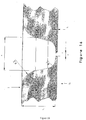
- Figures 13a, 14a, 15a are SEM images of various moulding surfaces, with corresponding figures 13b, 14b, 15b being their respective formed products (i.e. moulded PS).
- Figure 16 illustrates a schematic section through one part of a moulding surface.
- the moulding surface can be the lower moulding surface 2.
- Provided dimensions are an aperture 'a' (e.g. about 5 micrometres diameter), thickness of aperture t 1 (e.g. about 2 micrometres), height from aperture to top of moulding surface t 2 (e.g. about 50 micrometres), internal radius R1 (e.g. about 15 micrometres) and external radius R2 (e.g. about 25 micrometres), and opening 'b' (e.g. about 50 micrometres).
- Figures 17-21 illustrate the mould of figure 16 so used when material (e.g. polymer) is either flowed onto the mould from surface 2 I or surface 2 II .
- material e.g. polymer
- Figure 17 is an SEM image demonstrating the ability of a low stress material (e.g. liquid polymer) to be flowed through a small aperture (a) from surface 2 I to fill the mould cavity.
- a low stress material e.g. liquid polymer
- This figure exemplifies the invention's ability to pass a large volume of material through a small aperture enabling low stress high volume flow of polymer to form a high aspect ratio product.
- the volume of material in the cavity of the mould is over fifty times the volume of the material which may be held in the volume bounded by aperture (a) and thickness t I .
- Figure 18 is an SEM image of the moulding surface 2 II with aperture (a) shown.
- Figure 19 is an SEM image demonstrating the ability of a low stress material (e.g. liquid polymer) to be flowed from the moulding surface 2 I through to the other side 2 II of the mould. Image shows a polymer P(a) flowing out of the aperture (a) at the underside surface of 2 II .
- a low stress material e.g. liquid polymer
- Figure 20 is an SEM image of a formed polymer once removed from the moulding surface.
- the formed polymer product is the result from applying a polymer to moulding surface 2 I , but not flowed or pushed through to extend out beyond the aperture (a).
- Figure 21 is an SEM image of multiple of the products of figure 20 , demonstrating repeatability.
- the method of the invention comprises of forming an item in a manner to include a surface or surfaces with surface detail at a nano or near nano-scale, said method comprising applying by flowing or laying or depositing a formable material onto a surface, and forming the material.
- the method of the invention consists in a method of forming an item with at least one surface that includes nano-sized surface relief, said method comprising introducing onto a surface of a first platen a layer or layers of precursor material(s) to be formed, said material being in a liquid, or molten or near molten or non rigid state when introduced, applying a pressure onto the layer(s) by way of a second platen that is displaced towards said first platen, to at least in part form the precursor material, wherein one or both platen carry or have a surface that includes nano-sized surface relief to form the material with, at least in part, a negative thereof.
- the surface can be a substrate or platen receiving one side of a two-sided die or an imprinter die or a stamping mould or moulding surface.
- the moulding surface can be a part of a continuous forming tool (CFT), a moving belt former (MBF), an imprinter or a die or a suitable imprinter mould.
- CFT continuous forming tool
- MMF moving belt former
- imprinter or a die or a suitable imprinter mould.
- the die or moulding surface is desirably a material having a relatively high heat transfer rate or high thermal conductivity.
- the moulding surface may be a platen or a part of any one of, for example, a moving belt former, a stamp imprinter or a die imprinter or a stamping mould continuous forming tool.
- an endless belt system can be used in operating the process of this invention.
- the material in a manner that does not require the material (e.g.) polymer to move across the die surface, when the material is in a relaxed or a reduced stress condition allows reduced forming pressures for forming desired products.
- the reduction or near elimination of required forming pressures aides in minimising material stresses of deformation and may further reduce material shrinkage stresses when changing from a molten state or a liquid phase to a solid state or solid phase.
- this invention enables the forming of moulded products having minimal surface stress or tension during the forming process which may be imparted to the product so formed.
- the material may be at or near a substantially molten state when applying to the surface of a forming tool.
- the material may be in or near a substantially liquid phase when continuously applying to the surface of a forming tool. Such characteristics allow for the flowable application of the material.
- the material may be applied to the surface by flowing until a sheet of material substantially covering the surface is achieved.
- the heat transfer characteristics of the material may at least in part contribute to the maximum depth of material able to be applied to the surface for a subsequent forming operation.
- a temperature controllable cooling zone can allow production of high heat capacity materials or products of increased depth or thickness in allowing the material (polymer) to reduce to below its (or their) glass transition temperatures prior to removal of the material from the moulding surface.
- the material can be applied to the surface to a depth of less than about 50, 40, 30, 20, 10 mm, or less than about 5 mm, or less than about 3 mm, or less than about 2 mm. Yet further, the material is to a depth of 0.1 mm to about 3 mm. Alternatively, the depth is about 4, or 3, or 2 or 1 mm.
- the depth of material applied to the surface can be to a depth of at least about 0.5, 1, 2, 3, 4, 5, 6, 7, 8, 9, 10, 15, 20, 25, 30, 35 40, 45, 50 or 55 micrometres or about 56, 60, 65, 70, 75, 80, 85, 90, 95, 100, 105, 110, 115, 120, 125, 130, 135, 140, 145, 150, 155, 160, 165, 170, 175, 180, 185, 190, 195, 200, 220, 240, 260, 280, 290, 300, 350, 400, 450, 500, 550, 600, 650, 700, 750, 800, 850, 900, 950, 1000, 1050, 1100, 1150, 1200, 1250, 1300, 1350, 1400, 1450, 1500, 1550, 1600, 1650, 1700, 1750, 1800, 1850, 1900, 1950, 2000, 2050, 2100, 2150, 2200, 2250, 2300, 2350, 2400, 2450,
- the temperature can be controlled to be about 230 °C on contact with the surface
- the material is polycarbonate
- its temperature can be controlled to be about 300 °C on contact with the surface.
- Temperature control can be achieved by any manner of heat regulatory systems, for example electrical heaters or heat exchangers. Temperature control of the surface or of parts of the forming tools can also be controlled. Again, these may be by temperature regulators such as electrical heating systems, infra-red (IR) or other heat exchangers, for example hot oil systems for heating of platens of a forming tool. It will be understood that other methods of heating surfaces or maintaining surface temperatures is contemplated and not limited to those systems described herein only.
- IR infra-red
- the material may be temperature controlled according to predetermined material rheological characteristics, for example to control the physical properties of the material such as to a molten or semi-molten or liquid phase depending on its viscosity or malleability at particular temperatures.
- inputting energy to the material to form a semi-molten, molten or liquid phase of material and allowing the material to collect and pool may assist in subsequent flowing or lying of the material onto the surface.
- the material can be supplied to the surface in a semi-molten, molten or liquid phase. Alternatively, the material may be supplied to the surface in a sheet form.
- Suitable materials may involve one or more of: a molten mouldable material, a thermoformable material applied at a thermo-formable temperature, a thermoformable material to be heated by the surface or a forming tool or tools to a formable condition, a thermoformable material or molten mouldable material to be cooled by the surface or a forming tool or tools or otherwise, a thermoformable material to be thermoset by the surface or a forming tool or tools, and any of the foregoing together with one or more material of a different character.
- the present invention can be used with any flowable material, or a plastically deformable material such as for example polymers and metals.
- a plastically deformable material such as for example polymers and metals.
- most preferred materials include thermosetting polymers or thermoplastic polymers.
- Polymeric materials may include hydrocarbonaceous materials, including polymeric materials comprised of plant derived oil materials as recent trends suggest will become more widely available.
- Particularly suitable and contemplated materials include, but are not limited to the following, polymeric composites, polycarbonates (PC), polystyrenes (PS), general purpose polystyrenes (GPPS) or polymethyl methacrylates (PMMA).
- Materials that may be particularly suitable for optical media applications include, but are not limited to the following: ultraviolet stabilised thermoplastic polyurethanes, polycarbonates, polymethyl methacrylates, or general purpose polystyrenes.
- Suitable materials include conductive polymers and polymers suitable for wound dressings.
- metals metal alloys pure metals
- metallic oxides such as for example ceramics that may be sintered as part of a forming process or a subsequent process step to a forming operation
- non-crystalline ceramics such as for example carbides, borides, nitrides or silicides, or composites of these for example particle reinforced or combinations of oxide and non-oxide ceramics.
- metallic oxides such as oxides of alumina or zirconia, ceramics are to be formed
- the forming step may provide for forming of a green body or intermediates of a green body and a sintered item.
- Ceramics optionally provided in a slurry form or on a supporting substrate for subsequent forming operation may include: Barium titanate (often mixed with strontium titanate), Bismuth strontium calcium copper oxide, Boron nitride, Ferrite (Fe 3 O 4 ), Lead zirconate titanate, Magnesium diboride (MgB 2 ), Sialons / Silicon Aluminium Oxynitrides, Silicon carbide (SiC), Silicon nitride (Si 3 N 4 ), Steatite (magnesium silicates), Titanium Carbide, Uranium oxide (UO 2 ), Yttrium barium copper oxide (YBa 2 Cu 3 O 7-x , Zinc oxide (ZnO), Zirconium dioxide (zirconia).
- Suitable materials may desirably meet the flowable characteristic requirements.
- the material can be temperature controlled before applying to the surface.
- the material can be temperature controlled when applied to the surface.
- the material can be temperature controlled before applying to the surface and temperature controlled when applied to the surface.
- Temperature control can be achieved by measuring the temperature of the material and adjusting it by heaters.
- the heaters can be direct heaters, such as an electrical heater immersed in the material, or can an indirect heater(s) such as a heat exchanger imparting heat from a heat transfer fluid through a conductive surface to the material to be heated (e.g. a shell and tube heat exchanger).
- the surface or surfaces of the forming device can be heated to maintain temperature of the material to be formed or being formed. Provision of a heated surface may also assist in slowing the cooling or annealing of the material or rate of freezing of the material to below the T g of the material being processed before, during or after a forming operation.
- the surface used for the forming operation can be configured or arranged according to predetermined products to be formed.
- the imprinting or forming surface can be formed of metal coated nanotubes arranged or configured as desired, although other surface mould methods are also contemplated for us in this invention.
- Advantages of using a continuous forming tool may include one or more of: the ability to vary the pressure in the forming zone, lateral and axial expansion of forming blocks, raising and lowering of bottom track/platen with moulding surface, ability to vary clamping pressure of the machine between runs and over the length of track.
- CFT manufacturing technology can be used for flat sheet and many other profiles, for example, three-dimension shapes, asymmetric forms and is not limited to axially symmetric forms (for example pipes) or optical lenses. Further advantages of this manufacturing technology include: accommodating of intermediate processes, such as injection moulding, part insertion, top and bottom tracks/platens can differ in length and speed, high degree of accuracy alignment of mating dies, ability to control temperature of each forming block and/or each track separately, high forming speeds, forming block side plates take load, not faces and edges of forming blocks, can work with molten and semi-molten material(s), liquid or semi-liquid material(s) flow form to bottom die and then are pressure formed, very small shapes can be imprinted, at least down to or even below 1 nanometre in width or depth, and the capability of having non-linear pressure forming zones.
- the present invention advantageously provides for the flowing or lying of a polymer continuously on to a die or moulding surface in a way that the polymer does not flow across the die or moulding surface.
- the die or moulding surface is controlled or allowed to be at or close to the temperature of the polymer, the polymer being at or close to its liquid phase.
- the polymer is applied and held on the die or moulding surface in a manner such that the polymer is not moved across the die or moulding surface, the polymer moving due to gravity but not any other forces.
- the polymer is held in its form in the mould for a sufficient time until a compression moulding force is applied.
- the process of the invention is designed to impart minimal stress into the polymer during forming.
- the polymer is provided to the die or moulding surface when in a relaxed state, preferably its most relaxed state possible (i.e. liquid phase) and the amount of movement of the polymer is minimalised by only taking up the surface pattern of the die or moulding surface.
- the polymer is as close to its liquid phase as possible and is laid directly fully across/onto the die or moulding surface.
- the polymer need not be moved significantly across the mould surface to form the surface pattern or relief.
- the upper die or moulding surface is used to apply minimal pressure, for example in the range of 1-3 kg/cm2, to finish or move the polymer into the form of the surface pattern or relief of the moulding surface.
- the forming zone can be an extension of the heating zone.
- the cooling zone is only initiated or begins once the polymer to be formed has been "shaped". In comparison to existing processes, normally the cooling zone is provided immediately on exit or after exiting the extruder or injection moulder.
- the process of this invention is able to transfer a liquid phase polymer into a compression zone at sufficient speed and to maintain the polymer in its liquid phase without significant movement of the polymer across the die or moulding surface,
- the process imparts almost no stress in the polymer during forming - this is due to the polymer being in liquid phase, totally relaxed, minimal movement of the polymer across the die surface, the temperature of the die surface during forming being close to the polymer temperature, a controlled cooling cycle and the high speed of the forming process.
- the polymer is not injected or subjected to high forces/pressures or large flow paths.
- Products produced have lower chance of distortion in use - particularly in elevated temperature and/or exposure to chemicals - causing relaxation of any internal polymer stress, such as shear stress or forming stresses - which otherwise cause distortion of patterns formed.
- a highly thermally conductive die or moulding surface enables the die surface to rapidly take up or be increased or adjusted to the polymer's temperature on application to the die surface. Likewise, such a die or moulding surface is then able to allow cooling or heat transfer away from the polymer when in contact with the die surface.
- this invention enables the forming the polymer with pressure from about 1 kg/cm 2 to about 3 kg/cm 2 , although as previously described other pressures or pressure ranges may be used in the process. These particular forming pressures are relatively very low compared to known forming techniques. Alternatively, the pressure applied may be less than about 1 kg/cm2, optionally about 0.9, 0.8, 0.7, 0.6, 0.5, 0.4, 0.3, 0.2, 0.1 kg/cm 2. .
- Known techniques for injection moulding are often in the region of about 260 - 350kg/cm 2 .
- the ability to form multiple polymers on the moulding surface is enabled with this invention, for example the forming of two polymers simultaneously is possible.
- the alignment of patterns on either side of the extrusion is achieved through the alignment the die surfaces. Alignment can be controlled either through physical alignment of the surfaces by using taper interference or other common physical methods or by controlling the location and relative speeds of the die surfaces through sensor feedback from the die surfaces.
- Aligning the patterns on either side of a product may be used to enhance the optical properties of the product.
- the invention further provides for a process which can vary heating zones HZ and cooling zones CZ time and length, the extruder die height, the speed differential between the extrusion melt from the extruder die head and the process speed to control extrusion gauge and width, including speed control to vary the radius of the extrusion melt applied onto the die or moulding surface.
- Adjusting the variables in relation to process speed, length of heating time, length of cooling time, width of process and productivity can all be used to produce desired products.
- a limiting factor in operation of the invention is currently understood to be extrusion speed, although this may be increased as control of extrudate flow is improved.
- This invention is considered appropriate for those materials, such as polymers, capable of extrusion, including processing of a wide range of polymer viscosities, from about 1 MFI to about 50 (or even greater) MFI (MFI being the 'melt flow index'). Typically this is not possible with other techniques, such as in extrusion, hot embossing or injection moulding.
- Extrusion gauges from about 10 (or less) micrometers to about 20 mm are contemplated, including the patterning of large surface areas, such as for example about 3 m in width or may be wider than this depending on the necessary application or machine or moulding surface to be used.
- the present invention is enabled for the patterning across the total width D of an extrudate.
- other production processes are usually only capable of producing up to about 8" (inch) width products (e.g. wafers).
- a continuous process both a continuous feed of polymer in to the process and a continuous product production, is possible with no joins in the pattern or surface relief pattern being so formed.
- the product being formed can be moulded by the moulding surfaces around three-dimensional surfaces, not just flat or planar surfaces.
- the present invention further contributes to the ability to combine normally non-compatible materials due to their different processing requirements (e.g. glass transition temperatures or MFI or melt flow viscosity at once).
- processing requirements e.g. glass transition temperatures or MFI or melt flow viscosity at once.
- MFI glass transition temperatures
- TPU thermoplastic polyurethane
- the present invention avoids other problems in the prior art, such as "roll-stack chatter” which is apparent under normal extrusion roll stack processing. "Chatter” occurs due to differential speed between the roll stack's rollers during the forming due to pressure, motor dive control and friction influences.
- TPU thermoplastic polyurethane
- PP polypropylene
- Example items that the method according to the present invention can facilitate the forming of include: membranes for separation such as for separation of components from or within water, chemicals, gases, blood, or use within fuel cells, sensor devices, light diffusers, light emitters, wave reflecting or absorbing such as radar etc, electronic circuits or circuitry, particle alignment or aligning technologies, water repellents or water repelling technologies such as hydrophobic materials, optical media such as a liquid crystal display (“LCD”) or a compact disc (“CD”) or a digital video disc (“DVD”) technology or a photo-voltaic cell, memory storage devices, medical devices such as for skin repair or wound repair (e.g.
- membranes for separation such as for separation of components from or within water, chemicals, gases, blood, or use within fuel cells
- sensor devices light diffusers, light emitters, wave reflecting or absorbing such as radar etc
- electronic circuits or circuitry particle alignment or aligning technologies
- water repellents or water repelling technologies such as hydrophobic materials
- optical media such as a liquid crystal display (“LCD
- Particularly preferred items may include forming of or precursors for optical media such as photovoltaic cells, compact discs (CD), digital video discs (DVD), liquid crystal displays (“LCD”) or elements of conductive circuits or circuitry, including non-reflective or anti-reflective patterns or films for subsequent metalising and removal of the formed material to leave a metal negative image of the formed material (for example the formed product can be used to for the base for a subsequent metallisation treatment).
- optical media such as photovoltaic cells, compact discs (CD), digital video discs (DVD), liquid crystal displays (“LCD”) or elements of conductive circuits or circuitry, including non-reflective or anti-reflective patterns or films for subsequent metalising and removal of the formed material to leave a metal negative image of the formed material (for example the formed product can be used to for the base for a subsequent metallisation treatment).
- Polystyrene is:
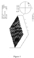
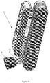
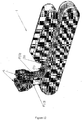
- the product thus formed is that shown in Figure 1 with product analysis shown in Figure 2 and an atomic force microscope image of a part of the product shown in Figure 3 .
- Polycarbonate is:
- PMMA Polymethyl methacrylate
- table 2 above provides details of the approximate temperature profile of PMMA material being processed as it is processed according to this invention. Temperature zones TZ-1, TZ-2, TZ-3, TZ-4, TZ-5, TZ-6, TZ-7 correspond to the various zones of the process illustrated by Figure 6.
- Figure 6 provides graphical representation of the temperature profile of a material as it passes through the process of the invention.
- PS Polystyrene
Landscapes
- Engineering & Computer Science (AREA)
- Mechanical Engineering (AREA)
- Physics & Mathematics (AREA)
- Thermal Sciences (AREA)
- Manufacturing & Machinery (AREA)
- Chemical & Material Sciences (AREA)
- Crystallography & Structural Chemistry (AREA)
- Nanotechnology (AREA)
- Casting Or Compression Moulding Of Plastics Or The Like (AREA)
- Extrusion Moulding Of Plastics Or The Like (AREA)
- Shaping Of Tube Ends By Bending Or Straightening (AREA)
- Processing And Handling Of Plastics And Other Materials For Molding In General (AREA)
Applications Claiming Priority (2)
| Application Number | Priority Date | Filing Date | Title |
|---|---|---|---|
| AU2008905211A AU2008905211A0 (en) | 2008-10-07 | Forming methods | |
| PCT/NZ2009/000214 WO2010041962A1 (en) | 2008-10-07 | 2009-10-07 | Forming methods |
Publications (3)
| Publication Number | Publication Date |
|---|---|
| EP2346661A1 EP2346661A1 (en) | 2011-07-27 |
| EP2346661A4 EP2346661A4 (en) | 2017-03-01 |
| EP2346661B1 true EP2346661B1 (en) | 2020-01-22 |
Family
ID=42100759
Family Applications (1)
| Application Number | Title | Priority Date | Filing Date |
|---|---|---|---|
| EP09819440.0A Active EP2346661B1 (en) | 2008-10-07 | 2009-10-07 | Forming methods |
Country Status (9)
| Country | Link |
|---|---|
| US (2) | US9242396B2 (da) |
| EP (1) | EP2346661B1 (da) |
| JP (1) | JP5622733B2 (da) |
| KR (1) | KR101805000B1 (da) |
| CN (1) | CN102202857B (da) |
| AU (1) | AU2009302979B2 (da) |
| CA (1) | CA2775742C (da) |
| DK (1) | DK2346661T3 (da) |
| WO (1) | WO2010041962A1 (da) |
Families Citing this family (11)
| Publication number | Priority date | Publication date | Assignee | Title |
|---|---|---|---|---|
| KR101502257B1 (ko) * | 2010-12-22 | 2015-03-12 | 더 재팬 스틸 워크스 엘티디 | 미세구조체의 제조방법 |
| US9108338B2 (en) * | 2011-04-13 | 2015-08-18 | Align Technology, Inc. | Methods and systems for thermal forming an object |
| US9587857B2 (en) | 2011-04-25 | 2017-03-07 | Morningside Technology Ventures Ltd | Polymeric solar concentrator and solar thermal device incorporating same |
| ITMI20121679A1 (it) * | 2012-10-08 | 2014-04-09 | Saipem Spa | Metodo, apparecchiatura e stazione di lavoro per applicare un foglio protettivo di materiale polimerico a una tubazione e programma per elaboratore per attuare il metodo |
| JP6006653B2 (ja) * | 2013-02-04 | 2016-10-12 | 出光興産株式会社 | ポリカーボネート樹脂用押出造粒装置およびポリカーボネート樹脂押出造粒方法 |
| KR102219703B1 (ko) * | 2014-05-07 | 2021-02-24 | 삼성전자주식회사 | 임프린트를 이용한 패터닝 방법, 이를 이용하여 제작된 패턴 구조체 및 임프린팅 시스템 |
| US10302847B2 (en) * | 2015-05-22 | 2019-05-28 | Microsoft Technology Licensing, Llc | Micro injection-molded articles |
| US10766185B2 (en) | 2015-10-13 | 2020-09-08 | The Boeing Company | Methods and apparatus for forming microscopic features on a film layer |
| DE102021105459A1 (de) * | 2021-03-08 | 2022-09-08 | Bayerische Motoren Werke Aktiengesellschaft | Kalandriervorrichtung für die herstellung einer elektrode |
| US11904510B2 (en) * | 2022-02-10 | 2024-02-20 | The Boeing Company | Continuous compression molding machines and methods of continuous compression molding a consolidated thermoplastic matrix composite material |
| CN115401842B (zh) * | 2022-08-15 | 2024-07-02 | 安徽康盛橡塑科技有限公司 | 一种橡胶制品生产用成型装置及其成型方法 |
Family Cites Families (46)
| Publication number | Priority date | Publication date | Assignee | Title |
|---|---|---|---|---|
| US2764193A (en) | 1954-01-11 | 1956-09-25 | Coruply Corp | Endless web corrugating machine |
| CH456134A (de) | 1967-07-26 | 1968-05-15 | Jetzer Raimund | Verfahren zur Herstellung von Pressplatten |
| DE2061027C3 (de) | 1970-12-11 | 1982-03-04 | Wilhelm 8730 Bad Kissingen Hegler | Vorrichtung zum Anbringen einer Querprofilierung an einem Rohr aus thermoplastischem Kunststoff |
| DE2501044B2 (de) | 1975-01-13 | 1980-01-10 | Fraenkische Isolierrohr- & Metallwaren-Werke, Gebr. Kirchner, 8729 Koenigsberg | Vorrichtung zum Herstellen von Wellrohren aus thermoplastischem Kunststoff |
| US4319872A (en) | 1976-12-01 | 1982-03-16 | Lupke Gerd Paul Heinrich | Apparatus for producing thermoplastic tubing |
| DE2832350A1 (de) | 1978-07-22 | 1980-01-31 | Wilhelm Hegler | Vorrichtung zur herstellung von rohren aus thermoplastischem kunststoff mit querprofilierung |
| DE3027045A1 (de) | 1980-07-17 | 1982-02-11 | Hegler, Wilhelm, 8730 Bad Kissingen | Flach-hohlkoerper, insbesondere lueftungs- und drainage- bzw. absorber-platte |
| DE3279862D1 (en) | 1981-06-15 | 1989-09-14 | Wavin Bv | Apparatus for making profiled plastics tube |
| JPS59138418A (ja) | 1983-01-27 | 1984-08-08 | Toyobo Co Ltd | ブロ−成形プラスチツクパイプの製造方法および装置 |
| FR2565155B1 (fr) | 1984-05-30 | 1988-06-17 | Gambini Romain | Dispositif pour le moulage et le demoulage rapide d'agglomeres |
| DE3530309A1 (de) * | 1985-08-24 | 1987-02-26 | Held Kurt | Verfahren und vorrichtung zum kontinuierlichen herstellen thermoplastischer kunststoffbahnen |
| US4956140A (en) * | 1985-12-09 | 1990-09-11 | Aluminum Company Of America Alcoa Laboratories | Methods of and apparatus for producing biaxially oriented polymer product |
| JPS62181112A (ja) * | 1986-02-06 | 1987-08-08 | Meiwa Sangyo Kk | 複合形成体の製造方法 |
| US5053180A (en) * | 1986-11-24 | 1991-10-01 | Aluminum Company Of America | Process for deformation of amorphous polymers |
| US4789322A (en) | 1987-11-23 | 1988-12-06 | Harry Chan | Corrugator with intermeshing overlapping moldblock halves |
| US5028372A (en) * | 1988-06-30 | 1991-07-02 | E. I. Du Pont De Nemours And Company | Method for producing para-aramid pulp |
| JP2565375B2 (ja) * | 1988-06-30 | 1996-12-18 | タキロン株式会社 | 連続プレス成形装置 |
| US5167781A (en) | 1990-04-06 | 1992-12-01 | Kemcast Partners-1989 | Continuous plastics molding process and apparatus |
| US5352111A (en) | 1990-12-19 | 1994-10-04 | Selbak's Cookie Cones, Inc. | Apparatus for removing a hand held food product from a baking mold |
| DE4129190A1 (de) * | 1991-09-03 | 1993-03-04 | Held Kurt | Verfahren und vorrichtung zur kontinuierlichen herstellung von harzimpraegnierten materialbahnen |
| DE4210482A1 (de) | 1992-03-31 | 1993-10-07 | Wilhelm Hegler | Verfahren und Vorrichtung zur fortlaufenden Herstellung eines Verbundrohres mit Rohr-Muffe |
| US5582849A (en) | 1994-05-06 | 1996-12-10 | Lupke; Manfred A. A. | Travelling mold with mold block carriers |
| US5843504A (en) * | 1996-10-15 | 1998-12-01 | Townsend Engineering Company | Method and apparatus for coagulating the outer surface of a sausage strand discharged from a sausage extruding machine |
| JPH11927A (ja) * | 1997-06-11 | 1999-01-06 | Nisshinbo Ind Inc | 成形装置 |
| JPH11928A (ja) | 1997-06-11 | 1999-01-06 | Osada Giken Kk | 土木建築用部材及びその製造方法 |
| TW453944B (en) | 1998-11-02 | 2001-09-11 | Rohm & Amp Haas Company | High quality plastic sheet, apparatus for producing same and their optical and electronic display applications |
| CA2271395C (en) | 1999-05-07 | 2006-07-11 | Manfred A. A. Lupke | Molding apparatus with mold block replacement system |
| DE19922726A1 (de) | 1999-05-18 | 2000-11-23 | Ralph Peter Hegler | Vorrichtung zur Herstellung von Kunststoff-Wellrohren |
| US6908295B2 (en) * | 2000-06-16 | 2005-06-21 | Avery Dennison Corporation | Process and apparatus for embossing precise microstructures and embossing tool for making same |
| WO2001098066A1 (en) * | 2000-06-16 | 2001-12-27 | Avery Dennison Corporation | A process and apparatus for precise embossing |
| JP4657494B2 (ja) | 2001-05-29 | 2011-03-23 | 株式会社日本触媒 | 多孔質製品の製造方法 |
| JP2003067625A (ja) | 2001-08-24 | 2003-03-07 | Earth Brown Kk | インターネットのホームページを利用した書類の配布方法 |
| JP2003288635A (ja) | 2002-01-28 | 2003-10-10 | Fuji Electric Co Ltd | 商品見本照明装置 |
| WO2003064300A1 (en) * | 2002-01-28 | 2003-08-07 | Kabushiki Kaisha Bridgestone | Method and device for transferring extrusion-molded articles |
| JP2003347042A (ja) | 2002-05-24 | 2003-12-05 | Denso Corp | 有機電子デバイス用の封止膜およびその製造方法 |
| DE10257365B3 (de) | 2002-12-09 | 2004-06-03 | Unicor Gmbh Rahn Plastmaschinen | Vorrichtung zur Herstellung von Querrippenrohren |
| US20050029708A1 (en) | 2003-08-05 | 2005-02-10 | General Electric Company | Process and apparatus for embossing a film surface |
| JP2005144771A (ja) | 2003-11-13 | 2005-06-09 | Jsr Corp | 表面意匠性フィルムまたはシートの製造方法、および表面意匠性フィルムまたはシート |
| CN1251850C (zh) | 2004-09-24 | 2006-04-19 | 司国权 | 轻质条板的自动化无托板生产工艺及其生产系统 |
| JP4665608B2 (ja) * | 2005-05-25 | 2011-04-06 | 株式会社日立プラントテクノロジー | 微細構造転写装置 |
| JP5386774B2 (ja) * | 2005-09-20 | 2014-01-15 | 東レ株式会社 | 易表面賦形性シート積層体、それを用いた表面賦形方法及び成形品 |
| EP1957250B1 (en) | 2005-11-16 | 2018-05-23 | Manufacturing Systems Limited | Improvements in or relating to forming apparatus |
| JP4854383B2 (ja) | 2006-05-15 | 2012-01-18 | アピックヤマダ株式会社 | インプリント方法およびナノ・インプリント装置 |
| KR100730415B1 (ko) * | 2006-12-20 | 2007-06-19 | 제일모직주식회사 | 광학필름 제조장치 및 이를 이용한 광학필름 제조방법 |
| US8721933B2 (en) * | 2007-03-16 | 2014-05-13 | Dexerials Corporation | Optical sheet manufacture method and optical sheet |
| US20080229941A1 (en) * | 2007-03-19 | 2008-09-25 | Babak Heidari | Nano-imprinting apparatus and method |
-
2009
- 2009-10-07 WO PCT/NZ2009/000214 patent/WO2010041962A1/en not_active Ceased
- 2009-10-07 US US13/123,176 patent/US9242396B2/en active Active
- 2009-10-07 AU AU2009302979A patent/AU2009302979B2/en active Active
- 2009-10-07 JP JP2011530977A patent/JP5622733B2/ja active Active
- 2009-10-07 KR KR1020117010581A patent/KR101805000B1/ko active Active
- 2009-10-07 CA CA2775742A patent/CA2775742C/en active Active
- 2009-10-07 EP EP09819440.0A patent/EP2346661B1/en active Active
- 2009-10-07 DK DK09819440.0T patent/DK2346661T3/da active
- 2009-10-07 CN CN200980146940.9A patent/CN102202857B/zh active Active
-
2015
- 2015-12-21 US US14/976,962 patent/US9592627B2/en active Active
Non-Patent Citations (1)
| Title |
|---|
| None * |
Also Published As
| Publication number | Publication date |
|---|---|
| AU2009302979B2 (en) | 2016-09-15 |
| JP2012505095A (ja) | 2012-03-01 |
| CN102202857B (zh) | 2014-11-19 |
| KR20110091666A (ko) | 2011-08-12 |
| CA2775742A1 (en) | 2010-04-15 |
| CN102202857A (zh) | 2011-09-28 |
| WO2010041962A1 (en) | 2010-04-15 |
| DK2346661T3 (da) | 2020-03-02 |
| US20120100339A1 (en) | 2012-04-26 |
| EP2346661A1 (en) | 2011-07-27 |
| KR101805000B1 (ko) | 2017-12-07 |
| JP5622733B2 (ja) | 2014-11-12 |
| EP2346661A4 (en) | 2017-03-01 |
| AU2009302979A1 (en) | 2010-04-15 |
| US9242396B2 (en) | 2016-01-26 |
| CA2775742C (en) | 2017-07-11 |
| US20160185018A1 (en) | 2016-06-30 |
| US9592627B2 (en) | 2017-03-14 |
Similar Documents
| Publication | Publication Date | Title |
|---|---|---|
| EP2346661B1 (en) | Forming methods | |
| CN103624992B (zh) | 一种聚合物微结构的片材压制设备及压制加工方法 | |
| Xie et al. | Rapid hot embossing of polymer microstructures using carbide-bonded graphene coating on silicon stampers | |
| JP5320540B2 (ja) | 成形装置における又は成形装置に関する改良 | |
| KR102033709B1 (ko) | 벨트프레스식 플라스틱시트 제조장치 | |
| US11110632B2 (en) | Roll-molding | |
| US10618210B2 (en) | High capacity print station, method of making a polymer composite part, and polymer composite part | |
| EP2695720A1 (en) | Method for producing transparent recycled sheet, and transparent recycled sheet | |
| CN100532070C (zh) | 一种用以制造表面具有压花的板件的装置与方法 | |
| AU2013219175A1 (en) | Forming methods | |
| CN101005937A (zh) | 制备树脂板的方法 | |
| US20060244174A1 (en) | Advanced method and apparatus for cost-effectively and continuously producing expanded thermoformable honeycomb materials | |
| WO2019231980A1 (en) | High capacity print station, method of making a polymer composite part, and polymer composite part | |
| CN101360596A (zh) | 成形设备的改进或者涉及成形设备的改进 | |
| CN118269320A (zh) | 智能共挤模压热塑性玻璃钢防滑托盘生产线及生产工艺 | |
| CN203125827U (zh) | 片材延伸机构 | |
| US6976835B1 (en) | Manufacturing system and process | |
| US20140057077A1 (en) | Extrusion molding device, molded article, and method of producing the same | |
| US20250144862A1 (en) | High capacity print station, method of making a polymer composite part, and polymer composite part | |
| CN103341980A (zh) | 多层复合式打包带的生产方法 | |
| US20060157886A1 (en) | Method and apparatus for continuously producing discrete expanded thermoformable materials | |
| CN112743727A (zh) | 用于5g天线的薄膜制备方法 | |
| AU2024346261A1 (en) | Deformation control device for non-polyvinyl chloride wood-plastic plate, production line, and use | |
| CN120363519A (zh) | 一种卫生用品的高强度双拉透气薄膜的制造设备及其方法 | |
| CN2477347Y (zh) | 石化合成纸用押出压延装置 |
Legal Events
| Date | Code | Title | Description |
|---|---|---|---|
| PUAI | Public reference made under article 153(3) epc to a published international application that has entered the european phase |
Free format text: ORIGINAL CODE: 0009012 |
|
| 17P | Request for examination filed |
Effective date: 20110506 |
|
| AK | Designated contracting states |
Kind code of ref document: A1 Designated state(s): AT BE BG CH CY CZ DE DK EE ES FI FR GB GR HR HU IE IS IT LI LT LU LV MC MK MT NL NO PL PT RO SE SI SK SM TR |
|
| AX | Request for extension of the european patent |
Extension state: AL BA RS |
|
| DAX | Request for extension of the european patent (deleted) | ||
| RA4 | Supplementary search report drawn up and despatched (corrected) |
Effective date: 20170201 |
|
| RIC1 | Information provided on ipc code assigned before grant |
Ipc: B29L 31/00 20060101ALN20170126BHEP Ipc: B29C 43/48 20060101AFI20170126BHEP Ipc: B29C 39/06 20060101ALI20170126BHEP |
|
| STAA | Information on the status of an ep patent application or granted ep patent |
Free format text: STATUS: EXAMINATION IS IN PROGRESS |
|
| 17Q | First examination report despatched |
Effective date: 20180928 |
|
| RAP1 | Party data changed (applicant data changed or rights of an application transferred) |
Owner name: MANUFACTURING SYSTEMS LIMITED |
|
| REG | Reference to a national code |
Ref country code: DE Ref legal event code: R079 Ref document number: 602009061070 Country of ref document: DE Free format text: PREVIOUS MAIN CLASS: B29C0039060000 Ipc: B29C0043480000 |
|
| GRAP | Despatch of communication of intention to grant a patent |
Free format text: ORIGINAL CODE: EPIDOSNIGR1 |
|
| RIC1 | Information provided on ipc code assigned before grant |
Ipc: B29C 59/02 20060101ALN20190716BHEP Ipc: B29C 48/07 20190101ALI20190716BHEP Ipc: B29C 43/52 20060101ALI20190716BHEP Ipc: B29C 43/48 20060101AFI20190716BHEP Ipc: B29L 31/00 20060101ALN20190716BHEP Ipc: B29C 48/08 20190101ALI20190716BHEP Ipc: B29C 43/22 20060101ALI20190716BHEP Ipc: B29C 59/04 20060101ALI20190716BHEP Ipc: B29C 43/02 20060101ALN20190716BHEP Ipc: B29C 39/06 20060101ALI20190716BHEP Ipc: B29C 48/88 20190101ALI20190716BHEP |
|
| STAA | Information on the status of an ep patent application or granted ep patent |
Free format text: STATUS: GRANT OF PATENT IS INTENDED |
|
| RIC1 | Information provided on ipc code assigned before grant |
Ipc: B29C 43/52 20060101ALI20190806BHEP Ipc: B29C 59/04 20060101ALI20190806BHEP Ipc: B29C 39/06 20060101ALI20190806BHEP Ipc: B29C 48/88 20190101ALI20190806BHEP Ipc: B29C 48/07 20190101ALI20190806BHEP Ipc: B29C 48/08 20190101ALI20190806BHEP Ipc: B29C 43/48 20060101AFI20190806BHEP Ipc: B29C 43/22 20060101ALI20190806BHEP Ipc: B29L 31/00 20060101ALN20190806BHEP Ipc: B29C 43/02 20060101ALN20190806BHEP Ipc: B29C 59/02 20060101ALN20190806BHEP |
|
| INTG | Intention to grant announced |
Effective date: 20190822 |
|
| GRAS | Grant fee paid |
Free format text: ORIGINAL CODE: EPIDOSNIGR3 |
|
| GRAA | (expected) grant |
Free format text: ORIGINAL CODE: 0009210 |
|
| STAA | Information on the status of an ep patent application or granted ep patent |
Free format text: STATUS: THE PATENT HAS BEEN GRANTED |
|
| AK | Designated contracting states |
Kind code of ref document: B1 Designated state(s): AT BE BG CH CY CZ DE DK EE ES FI FR GB GR HR HU IE IS IT LI LT LU LV MC MK MT NL NO PL PT RO SE SI SK SM TR |
|
| REG | Reference to a national code |
Ref country code: GB Ref legal event code: FG4D |
|
| REG | Reference to a national code |
Ref country code: CH Ref legal event code: EP |
|
| REG | Reference to a national code |
Ref country code: DE Ref legal event code: R096 Ref document number: 602009061070 Country of ref document: DE |
|
| REG | Reference to a national code |
Ref country code: AT Ref legal event code: REF Ref document number: 1226639 Country of ref document: AT Kind code of ref document: T Effective date: 20200215 |
|
| REG | Reference to a national code |
Ref country code: IE Ref legal event code: FG4D |
|
| REG | Reference to a national code |
Ref country code: CH Ref legal event code: NV Representative=s name: VALIPAT S.A. C/O BOVARD SA NEUCHATEL, CH |
|
| REG | Reference to a national code |
Ref country code: DK Ref legal event code: T3 Effective date: 20200226 |
|
| RAP2 | Party data changed (patent owner data changed or rights of a patent transferred) |
Owner name: MANUFACTURING SYSTEMS LIMITED |
|
| REG | Reference to a national code |
Ref country code: NL Ref legal event code: FP |
|
| REG | Reference to a national code |
Ref country code: LT Ref legal event code: MG4D |
|
| PG25 | Lapsed in a contracting state [announced via postgrant information from national office to epo] |
Ref country code: FI Free format text: LAPSE BECAUSE OF FAILURE TO SUBMIT A TRANSLATION OF THE DESCRIPTION OR TO PAY THE FEE WITHIN THE PRESCRIBED TIME-LIMIT Effective date: 20200122 Ref country code: NO Free format text: LAPSE BECAUSE OF FAILURE TO SUBMIT A TRANSLATION OF THE DESCRIPTION OR TO PAY THE FEE WITHIN THE PRESCRIBED TIME-LIMIT Effective date: 20200422 Ref country code: PT Free format text: LAPSE BECAUSE OF FAILURE TO SUBMIT A TRANSLATION OF THE DESCRIPTION OR TO PAY THE FEE WITHIN THE PRESCRIBED TIME-LIMIT Effective date: 20200614 |
|
| PG25 | Lapsed in a contracting state [announced via postgrant information from national office to epo] |
Ref country code: HR Free format text: LAPSE BECAUSE OF FAILURE TO SUBMIT A TRANSLATION OF THE DESCRIPTION OR TO PAY THE FEE WITHIN THE PRESCRIBED TIME-LIMIT Effective date: 20200122 Ref country code: SE Free format text: LAPSE BECAUSE OF FAILURE TO SUBMIT A TRANSLATION OF THE DESCRIPTION OR TO PAY THE FEE WITHIN THE PRESCRIBED TIME-LIMIT Effective date: 20200122 Ref country code: LV Free format text: LAPSE BECAUSE OF FAILURE TO SUBMIT A TRANSLATION OF THE DESCRIPTION OR TO PAY THE FEE WITHIN THE PRESCRIBED TIME-LIMIT Effective date: 20200122 Ref country code: BG Free format text: LAPSE BECAUSE OF FAILURE TO SUBMIT A TRANSLATION OF THE DESCRIPTION OR TO PAY THE FEE WITHIN THE PRESCRIBED TIME-LIMIT Effective date: 20200422 Ref country code: IS Free format text: LAPSE BECAUSE OF FAILURE TO SUBMIT A TRANSLATION OF THE DESCRIPTION OR TO PAY THE FEE WITHIN THE PRESCRIBED TIME-LIMIT Effective date: 20200522 Ref country code: GR Free format text: LAPSE BECAUSE OF FAILURE TO SUBMIT A TRANSLATION OF THE DESCRIPTION OR TO PAY THE FEE WITHIN THE PRESCRIBED TIME-LIMIT Effective date: 20200423 |
|
| REG | Reference to a national code |
Ref country code: DE Ref legal event code: R097 Ref document number: 602009061070 Country of ref document: DE |
|
| PG25 | Lapsed in a contracting state [announced via postgrant information from national office to epo] |
Ref country code: CZ Free format text: LAPSE BECAUSE OF FAILURE TO SUBMIT A TRANSLATION OF THE DESCRIPTION OR TO PAY THE FEE WITHIN THE PRESCRIBED TIME-LIMIT Effective date: 20200122 Ref country code: SK Free format text: LAPSE BECAUSE OF FAILURE TO SUBMIT A TRANSLATION OF THE DESCRIPTION OR TO PAY THE FEE WITHIN THE PRESCRIBED TIME-LIMIT Effective date: 20200122 Ref country code: EE Free format text: LAPSE BECAUSE OF FAILURE TO SUBMIT A TRANSLATION OF THE DESCRIPTION OR TO PAY THE FEE WITHIN THE PRESCRIBED TIME-LIMIT Effective date: 20200122 Ref country code: SM Free format text: LAPSE BECAUSE OF FAILURE TO SUBMIT A TRANSLATION OF THE DESCRIPTION OR TO PAY THE FEE WITHIN THE PRESCRIBED TIME-LIMIT Effective date: 20200122 Ref country code: ES Free format text: LAPSE BECAUSE OF FAILURE TO SUBMIT A TRANSLATION OF THE DESCRIPTION OR TO PAY THE FEE WITHIN THE PRESCRIBED TIME-LIMIT Effective date: 20200122 Ref country code: LT Free format text: LAPSE BECAUSE OF FAILURE TO SUBMIT A TRANSLATION OF THE DESCRIPTION OR TO PAY THE FEE WITHIN THE PRESCRIBED TIME-LIMIT Effective date: 20200122 Ref country code: RO Free format text: LAPSE BECAUSE OF FAILURE TO SUBMIT A TRANSLATION OF THE DESCRIPTION OR TO PAY THE FEE WITHIN THE PRESCRIBED TIME-LIMIT Effective date: 20200122 |
|
| REG | Reference to a national code |
Ref country code: AT Ref legal event code: MK05 Ref document number: 1226639 Country of ref document: AT Kind code of ref document: T Effective date: 20200122 |
|
| PLBE | No opposition filed within time limit |
Free format text: ORIGINAL CODE: 0009261 |
|
| STAA | Information on the status of an ep patent application or granted ep patent |
Free format text: STATUS: NO OPPOSITION FILED WITHIN TIME LIMIT |
|
| 26N | No opposition filed |
Effective date: 20201023 |
|
| PG25 | Lapsed in a contracting state [announced via postgrant information from national office to epo] |
Ref country code: AT Free format text: LAPSE BECAUSE OF FAILURE TO SUBMIT A TRANSLATION OF THE DESCRIPTION OR TO PAY THE FEE WITHIN THE PRESCRIBED TIME-LIMIT Effective date: 20200122 |
|
| PG25 | Lapsed in a contracting state [announced via postgrant information from national office to epo] |
Ref country code: SI Free format text: LAPSE BECAUSE OF FAILURE TO SUBMIT A TRANSLATION OF THE DESCRIPTION OR TO PAY THE FEE WITHIN THE PRESCRIBED TIME-LIMIT Effective date: 20200122 Ref country code: PL Free format text: LAPSE BECAUSE OF FAILURE TO SUBMIT A TRANSLATION OF THE DESCRIPTION OR TO PAY THE FEE WITHIN THE PRESCRIBED TIME-LIMIT Effective date: 20200122 |
|
| PG25 | Lapsed in a contracting state [announced via postgrant information from national office to epo] |
Ref country code: MC Free format text: LAPSE BECAUSE OF FAILURE TO SUBMIT A TRANSLATION OF THE DESCRIPTION OR TO PAY THE FEE WITHIN THE PRESCRIBED TIME-LIMIT Effective date: 20200122 Ref country code: LU Free format text: LAPSE BECAUSE OF NON-PAYMENT OF DUE FEES Effective date: 20201007 |
|
| REG | Reference to a national code |
Ref country code: BE Ref legal event code: MM Effective date: 20201031 |
|
| PG25 | Lapsed in a contracting state [announced via postgrant information from national office to epo] |
Ref country code: BE Free format text: LAPSE BECAUSE OF NON-PAYMENT OF DUE FEES Effective date: 20201031 |
|
| PG25 | Lapsed in a contracting state [announced via postgrant information from national office to epo] |
Ref country code: TR Free format text: LAPSE BECAUSE OF FAILURE TO SUBMIT A TRANSLATION OF THE DESCRIPTION OR TO PAY THE FEE WITHIN THE PRESCRIBED TIME-LIMIT Effective date: 20200122 Ref country code: MT Free format text: LAPSE BECAUSE OF FAILURE TO SUBMIT A TRANSLATION OF THE DESCRIPTION OR TO PAY THE FEE WITHIN THE PRESCRIBED TIME-LIMIT Effective date: 20200122 Ref country code: CY Free format text: LAPSE BECAUSE OF FAILURE TO SUBMIT A TRANSLATION OF THE DESCRIPTION OR TO PAY THE FEE WITHIN THE PRESCRIBED TIME-LIMIT Effective date: 20200122 |
|
| PG25 | Lapsed in a contracting state [announced via postgrant information from national office to epo] |
Ref country code: MK Free format text: LAPSE BECAUSE OF FAILURE TO SUBMIT A TRANSLATION OF THE DESCRIPTION OR TO PAY THE FEE WITHIN THE PRESCRIBED TIME-LIMIT Effective date: 20200122 |
|
| P01 | Opt-out of the competence of the unified patent court (upc) registered |
Effective date: 20230609 |
|
| P02 | Opt-out of the competence of the unified patent court (upc) changed |
Effective date: 20230619 |
|
| REG | Reference to a national code |
Ref country code: CH Ref legal event code: U11 Free format text: ST27 STATUS EVENT CODE: U-0-0-U10-U11 (AS PROVIDED BY THE NATIONAL OFFICE) Effective date: 20251101 |
|
| PGFP | Annual fee paid to national office [announced via postgrant information from national office to epo] |
Ref country code: NL Payment date: 20251021 Year of fee payment: 17 |
|
| PGFP | Annual fee paid to national office [announced via postgrant information from national office to epo] |
Ref country code: DE Payment date: 20251029 Year of fee payment: 17 |
|
| PGFP | Annual fee paid to national office [announced via postgrant information from national office to epo] |
Ref country code: GB Payment date: 20251023 Year of fee payment: 17 |
|
| PGFP | Annual fee paid to national office [announced via postgrant information from national office to epo] |
Ref country code: DK Payment date: 20251022 Year of fee payment: 17 Ref country code: IT Payment date: 20251017 Year of fee payment: 17 |
|
| PGFP | Annual fee paid to national office [announced via postgrant information from national office to epo] |
Ref country code: FR Payment date: 20251027 Year of fee payment: 17 |
|
| PGFP | Annual fee paid to national office [announced via postgrant information from national office to epo] |
Ref country code: CH Payment date: 20251101 Year of fee payment: 17 |
|
| PGFP | Annual fee paid to national office [announced via postgrant information from national office to epo] |
Ref country code: IE Payment date: 20251019 Year of fee payment: 17 |