EP2617533A1 - Dispositif de commande de robot, système de robot, procédé de commande de robot - Google Patents
Dispositif de commande de robot, système de robot, procédé de commande de robot Download PDFInfo
- Publication number
- EP2617533A1 EP2617533A1 EP13151284.0A EP13151284A EP2617533A1 EP 2617533 A1 EP2617533 A1 EP 2617533A1 EP 13151284 A EP13151284 A EP 13151284A EP 2617533 A1 EP2617533 A1 EP 2617533A1
- Authority
- EP
- European Patent Office
- Prior art keywords
- robot
- value
- force
- displacement
- processing
- Prior art date
- Legal status (The legal status is an assumption and is not a legal conclusion. Google has not performed a legal analysis and makes no representation as to the accuracy of the status listed.)
- Withdrawn
Links
Images


Classifications
-
- B—PERFORMING OPERATIONS; TRANSPORTING
- B25—HAND TOOLS; PORTABLE POWER-DRIVEN TOOLS; MANIPULATORS
- B25J—MANIPULATORS; CHAMBERS PROVIDED WITH MANIPULATION DEVICES
- B25J9/00—Program-controlled manipulators
- B25J9/16—Program controls
- B25J9/1628—Program controls characterised by the control loop
- B25J9/1633—Program controls characterised by the control loop compliant, force, torque control, e.g. combined with position control
-
- B—PERFORMING OPERATIONS; TRANSPORTING
- B25—HAND TOOLS; PORTABLE POWER-DRIVEN TOOLS; MANIPULATORS
- B25J—MANIPULATORS; CHAMBERS PROVIDED WITH MANIPULATION DEVICES
- B25J9/00—Program-controlled manipulators
- B25J9/16—Program controls
- B25J9/1694—Program controls characterised by use of sensors other than normal servo-feedback from position, speed or acceleration sensors, perception control, multi-sensor controlled systems, sensor fusion
-
- B—PERFORMING OPERATIONS; TRANSPORTING
- B25—HAND TOOLS; PORTABLE POWER-DRIVEN TOOLS; MANIPULATORS
- B25J—MANIPULATORS; CHAMBERS PROVIDED WITH MANIPULATION DEVICES
- B25J9/00—Program-controlled manipulators
- B25J9/16—Program controls
- B25J9/1602—Program controls characterised by the control system, structure, architecture
- B25J9/1605—Simulation of manipulator lay-out, design, modelling of manipulator
-
- B—PERFORMING OPERATIONS; TRANSPORTING
- B25—HAND TOOLS; PORTABLE POWER-DRIVEN TOOLS; MANIPULATORS
- B25J—MANIPULATORS; CHAMBERS PROVIDED WITH MANIPULATION DEVICES
- B25J9/00—Program-controlled manipulators
- B25J9/16—Program controls
- B25J9/1628—Program controls characterised by the control loop
- B25J9/1648—Program controls characterised by the control loop non-linear control combined or not with linear control
-
- B—PERFORMING OPERATIONS; TRANSPORTING
- B25—HAND TOOLS; PORTABLE POWER-DRIVEN TOOLS; MANIPULATORS
- B25J—MANIPULATORS; CHAMBERS PROVIDED WITH MANIPULATION DEVICES
- B25J9/00—Program-controlled manipulators
- B25J9/16—Program controls
- B25J9/1656—Program controls characterised by programming, planning systems for manipulators
- B25J9/1664—Program controls characterised by programming, planning systems for manipulators characterised by motion, path, trajectory planning
-
- G—PHYSICS
- G05—CONTROLLING; REGULATING
- G05B—CONTROL OR REGULATING SYSTEMS IN GENERAL; FUNCTIONAL ELEMENTS OF SUCH SYSTEMS; MONITORING OR TESTING ARRANGEMENTS FOR SUCH SYSTEMS OR ELEMENTS
- G05B19/00—Program-control systems
- G05B19/02—Program-control systems electric
- G05B19/18—Numerical control [NC], i.e. automatically operating machines, in particular machine tools, e.g. in a manufacturing environment, so as to execute positioning, movement or co-ordinated operations by means of program data in numerical form
- G05B19/408—Numerical control [NC], i.e. automatically operating machines, in particular machine tools, e.g. in a manufacturing environment, so as to execute positioning, movement or co-ordinated operations by means of program data in numerical form characterised by data handling or data format, e.g. reading, buffering or conversion of data
- G05B19/4086—Coordinate conversions; Other special calculations
-
- G—PHYSICS
- G05—CONTROLLING; REGULATING
- G05B—CONTROL OR REGULATING SYSTEMS IN GENERAL; FUNCTIONAL ELEMENTS OF SUCH SYSTEMS; MONITORING OR TESTING ARRANGEMENTS FOR SUCH SYSTEMS OR ELEMENTS
- G05B2219/00—Program-control systems
- G05B2219/30—Nc systems
- G05B2219/39—Robotics, robotics to robotics hand
- G05B2219/39343—Force based impedance control
-
- G—PHYSICS
- G05—CONTROLLING; REGULATING
- G05B—CONTROL OR REGULATING SYSTEMS IN GENERAL; FUNCTIONAL ELEMENTS OF SUCH SYSTEMS; MONITORING OR TESTING ARRANGEMENTS FOR SUCH SYSTEMS OR ELEMENTS
- G05B2219/00—Program-control systems
- G05B2219/30—Nc systems
- G05B2219/41—Servomotor, servo controller till figures
- G05B2219/41124—Nonlinear compensation
-
- G—PHYSICS
- G05—CONTROLLING; REGULATING
- G05B—CONTROL OR REGULATING SYSTEMS IN GENERAL; FUNCTIONAL ELEMENTS OF SUCH SYSTEMS; MONITORING OR TESTING ARRANGEMENTS FOR SUCH SYSTEMS OR ELEMENTS
- G05B2219/00—Program-control systems
- G05B2219/30—Nc systems
- G05B2219/42—Servomotor, servo controller kind till VSS
- G05B2219/42092—Position and force control loop together
-
- G—PHYSICS
- G05—CONTROLLING; REGULATING
- G05B—CONTROL OR REGULATING SYSTEMS IN GENERAL; FUNCTIONAL ELEMENTS OF SUCH SYSTEMS; MONITORING OR TESTING ARRANGEMENTS FOR SUCH SYSTEMS OR ELEMENTS
- G05B2219/00—Program-control systems
- G05B2219/30—Nc systems
- G05B2219/42—Servomotor, servo controller kind till VSS
- G05B2219/42267—Stability analysis
-
- G—PHYSICS
- G06—COMPUTING OR CALCULATING; COUNTING
- G06F—ELECTRIC DIGITAL DATA PROCESSING
- G06F17/00—Digital computing or data processing equipment or methods, specially adapted for specific functions
- G06F17/10—Complex mathematical operations
- G06F17/11—Complex mathematical operations for solving equations, e.g. nonlinear equations, general mathematical optimization problems
- G06F17/13—Differential equations
-
- Y—GENERAL TAGGING OF NEW TECHNOLOGICAL DEVELOPMENTS; GENERAL TAGGING OF CROSS-SECTIONAL TECHNOLOGIES SPANNING OVER SEVERAL SECTIONS OF THE IPC; TECHNICAL SUBJECTS COVERED BY FORMER USPC CROSS-REFERENCE ART COLLECTIONS [XRACs] AND DIGESTS
- Y10—TECHNICAL SUBJECTS COVERED BY FORMER USPC
- Y10S—TECHNICAL SUBJECTS COVERED BY FORMER USPC CROSS-REFERENCE ART COLLECTIONS [XRACs] AND DIGESTS
- Y10S901/00—Robots
- Y10S901/02—Arm motion controller
- Y10S901/09—Closed loop, sensor feedback controls arm movement
Definitions
- the present invention relates to a robot controller, a robot system, a robot control method, etc.
- Operations using robots such as manipulators include operations with various constraints, for example, in contact with objects.
- force control is often required in addition to location control.
- movement in response to the reaction force from the object is necessary in addition to simple location control.
- Representative methods of force control in robots include a method called impedance control.
- the impedance control is a control method of moving a robot, regardless of its real mass, viscosity property, and elasticity property, as if it had those values suitable for an operation.
- This is a control method of solving an equation of motion based on force information obtained from a force sensor attached to the robot and moving the robot according to the solution. By appropriately setting the equation of motion, the robot such as a manipulator can be moved as if it had predetermined mass, viscosity, and elasticity.
- Patent Document 1 JP-A-10-128685
- Patent Document 2 JP-A-2011-8360
- force is specified as expansion and contraction of a virtual spring (virtual displacement).
- Patent Document 1 and Patent Document 2 disclose methods of performing impedance control for linear output with respect to virtual displacement.
- Patent Document 1 discloses a method of performing nonlinear impedance control by using a function non-linear with respect to virtual displacement as the elasticity term of an equation of motion in force control.
- Patent Document 2 discloses a method of providing two (plural) control mechanisms and two control parameters and assuming a hyperplane called a sliding surface in a control state space, switching the two (plural) control mechanisms and the two control parameters depending on which of the spaces divided by the hyperplane contains the control state, and thereby, constraining the control state on the sliding surface and ensuring stability and convergence of the control system.
- An advantage of some aspects of the invention is to provide a robot controller, a robot system, a robot control method etc. that perform nonlinear impedance control and facilitate verification of stability of the solution of the equation of motion and realization as hardware.
- An aspect of the invention relates to a robot controller including a force control unit that outputs a correction value of a target track of a robot based on a detected sensor value acquired from a force sensor, a target value output unit that obtains a target value by performing correction processing on the target track based on the correction value and outputs the obtained target value, and a robot control unit that performs feedback control of the robot based on the target value, wherein the force control unit includes an impedance processing part that obtains a solution of an ordinary differential equation in force control as the correction value before conversion processing, and a nonlinear conversion part that obtains the correction value after the conversion processing by performing nonlinear conversion processing on the correction value before the conversion processing acquired from the impedance processing part and outputs the obtained correction value after the conversion processing.
- the nonlinear impedance control may be realized. Further, by using the combination of linear systems, stability of the solution of the equation of motion can be verified.
- a robot controller including a force control unit that outputs a correction value of a target track of a robot based on a detected sensor value acquired from a force sensor, a target value output unit that obtains a target value by performing correction processing on the target track based on the correction value and outputs the obtained target value, and a robot control unit that performs feedback control of the robot based on the target value
- the force control unit includes a nonlinear conversion part that performs nonlinear conversion processing on the detected sensor value acquired from the force sensor and obtains the detected sensor value after conversion processing, and an impedance processing part that obtains a solution of an ordinary differential equation in force control as the correction value based on the detected sensor value after the conversion processing acquired from the nonlinear conversion part.
- the nonlinear impedance control may be realized. Further, by using the combination of linear systems, stability of the solution of the equation of motion can be verified.
- the force control unit may perform the nonlinear conversion processing so that the first amount of displacement change may be larger than the second amount of displacement change when the virtual displacement is the first displacement larger than the second displacement, and output the correction value.
- the force control unit may perform the nonlinear conversion processing so that the first amount of displacement change may be smaller than the second amount of displacement change when the virtual displacement is the first displacement larger than the second displacement, and output the correction value.
- the force control unit may perform first force control when a direction of the virtual displacement with respect to the robot corresponding to the correction value is a first direction, and perform second force control different from the first force control when the direction of the virtual displacement is a second direction opposite to the first direction.
- the nonlinear conversion part may perform the nonlinear conversion processing using a sigmoid function on the correction value before the conversion processing acquired from the impedance processing part or the detected sensor value acquired from the force sensor.
- the impedance processing part may have a digital filter part that obtains the solution of the ordinary differential equation in force control as the correction value.
- the force control unit may determine stability of an operation of the digital filter part of obtaining the correction value, and obtain the solution of the ordinary differential equation in force control as the correction value if a determination that the operation of the digital filter part is stable is made.
- the ordinary differential equation may be an equation of motion having a virtual mass term, a virtual viscosity term, and a virtual elasticity term as coefficient parameters.
- Still another aspect of the invention relates to a robot system including the robot controller, and the robot that moves the respective parts based on the target value acquired from the target value output unit.
- Yet another aspect of the invention relates to a robot control method including obtaining a solution of an ordinary differential equation in force control as a correction value before conversion processing used for correction processing of a target track of a robot based on a detected sensor value acquired from a force sensor, obtaining the correction value after the conversion processing by performing nonlinear conversion processing on the obtained correction value before conversion processing, performing the correction processing on the target track of the robot to obtain a target value based on the obtained correction value after the conversion processing, and performing feedback control of the robot based on the obtained target value.
- Still yet another aspect of the invention relates to a robot control method including performing nonlinear conversion processing on a detected sensor value acquired from a force sensor, and thereby, obtaining the detected sensor value after conversion processing used for correction processing of a target track of a robot, obtaining a solution of an ordinary differential equation in force control as a correction value based on the obtained detected sensor value after the conversion processing, obtaining a target value by performing the correction processing on the target track of the robot based on the obtained correction value, and performing feedback control of the robot based on the obtained target value.
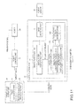
- Fig. 1 shows a basic configuration example of a robot controller and a robot system.
- Figs. 2A and 2B show one examples of the robot system.
- Figs. 3A to 3C are explanatory diagrams of force control.
- Figs. 4A and 4B are explanatory diagrams of compliance control.
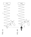
- Figs. 5A and 5B are explanatory diagrams of impedance control.
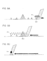
- Figs. 6A to 6C are explanatory diagrams of problems of linear impedance control.
- Fig. 7 shows a basic configuration example of a control system not including force sense feedback.
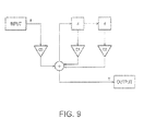
- Fig. 8 shows a basic configuration example of a control system including force sense feedback.
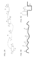
- Fig. 9 shows a basic form of a digital filter when a solution of an equation of motion is obtained.
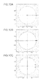
- Figs. 10A to 10C are explanatory diagrams of a stability determination method of the system.
- Fig. 11 shows a basic configuration example of a robot controller and a robot system using the digital filter.
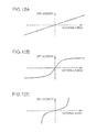
- Figs. 12A to 12C are explanatory diagrams of nonlinear impedance control.
- Fig. 13 shows a detailed system configuration example of the first embodiment.
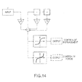
- Fig. 14 shows a digital filter of the first embodiment.
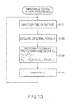
- Fig. 15 is a flowchart for explanation of impedance digital filter processing of the first embodiment.
- Fig. 16 shows linear impedance control response examples for sinusoidal external force.
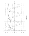
- Fig. 17 shows nonlinear impedance control response examples for sinusoidal external force.
- Fig. 18 shows nonlinear asymmetric impedance control response examples for sinusoidal external force.
- Fig. 19 shows a detailed system configuration example of the second embodiment.
- Fig. 20 shows a digital filter of the second embodiment.
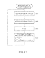
- Fig. 21 is a flowchart for explanation of impedance digital filter processing of the second embodiment.
- Figs. 22A and 22B show specific systems of obtaining target tracks, correction values, and target values.
- Fig. 1 shows a configuration example of a robot controller (manipulator controller) and a robot system including the controller of the embodiment. Note that the robot controller and the robot system of the embodiment are not limited to those having the configuration in Fig. 1 , and various modifications can be made by omitting part of their component elements and adding other component elements.
- the robot controller of the embodiment includes a force control unit 20, a target value output unit 60, and a robot control unit 80. Further, the robot system of the embodiment includes the robot controller and a robot 100 (force sensor 10).
- the target value output unit 60 outputs a target value of feedback control of the robot (manipulator in a narrow sense).
- the feedback control of the robot 100 is realized based on the target value.
- the target value is joint angle information of the robot or the like.
- the joint angle information of the robot is information representing angles of the respective joints (angles formed by joint axes and joint axes) in a link mechanism of arms of the robot, for example.
- the target value output unit 60 may include a track generation part 62 and an inverse kinematics processing part 64.
- the track generation part 62 outputs track information of the robot.
- the track information may include location information (x,y,z) of an end effector part (end point) of the robot and rotation angle information (u,v,w) around the respective coordinate axes.
- the inverse kinematics processing part 64 performs inverse kinematics processing based on the track information from the track generation part 62, and outputs the joint angle information of the robot as the target value, for example.
- the inverse kinematics processing is processing of calculating the movement of the robot having joints and processing of calculating the joint angle information or the like from the location and position of the end effector of the robot using inverse kinematics.
- the force control unit 20 (impedance control unit in a narrow sense) performs force control (force sense control) based on the sensor information from the force sensor 10 and outputs a correction value of the target value. Further, specifically, the force control unit 20 (impedance control unit) performs impedance control (or compliance control) based on sensor information (force information, moment information) from the force sensor 10.
- the force control is control with the addition of force feedback to location control in related art.
- the impedance control is a method of turning the ease of displacement (mechanical impedance) of the end effector part (hand) for external force into a desired condition by control.
- the control is, in a model in which a mass, a viscosity coefficient, and an elastic element are connected to the end effector part of the robot, to bring the part into contact with an object with the mass, viscosity coefficient, and the elastic coefficient set as targets.
- the force sensor 10 is a sensor that detects force as reaction force of the force by the robot 100 and moment.
- the force sensor 10 is typically attached to the wrist part of the arm of the robot 100, and the detected force and moment is used for various force control (impedance control) as sensor information.
- the robot control unit 80 performs feedback control of the robot based on the target value obtained from the target value output unit 60. Specifically, the unit performs the feedback control of the robot based on the target value output as a result of correction processing based on the correction value from the force control unit 20. For example, the unit performs the feedback control of the robot 100 based on the target value and a feedback signal from the robot 100.
- the robot control unit 80 includes plural drive control parts 82-1 to 82-N (motor control parts in a narrow sense), and outputs their control signals to drive parts 102-1 to 102-N of the robot 100.
- the drive parts 102-1 to 102-N are drive mechanisms for moving the respective joints of the robot 100 and realized by motors or the like, for example.
- Fig. 2A shows an example of the robot system including the robot controller of the embodiment.
- the robot system includes a control device 300 (information processing unit) and a robot 310 (robot 100 in Fig. 1 ).
- the control device 300 performs control processing of the robot 310. Specifically, the device performs control of moving the robot 310 based on movement sequence information (scenario information).
- the robot 310 has an arm 320 and a hand (grasping part) 330, and moves according to the movement command from the control device 300. For example, the robot performs movement of grasping and moving work placed on a pallet (not shown). Further, information of the position of the robot and the location of the work is detected based on taken image information acquired by an imaging device (not shown), and the detected information is sent to the control device 300.
- the robot controller of the embodiment is provided in the control device 300 in Fig. 2A , for example, and the robot controller is realized by hardware and programs of the control device 300. Further, according to the robot controller of the embodiment, performance requirement for the control hardware of the control device 300 or the like may be reduced and the robot 310 may be moved with high responsiveness.
- the robot main body 310 (robot) and the control device 300 (robot controller) are separately formed in Fig. 2A , however, the robot of the embodiment is not limited to that having the configuration in Fig. 2A , and the robot main body 310 and the control device 300 may be integrally formed as shown in Fig. 2B .
- the robot includes the robot main body 310 (having the arm 320 and the hand 330) and a base unit part that supports the robot main body 310, and the control device 300 is housed in the base unit part.
- wheels or the like are provided in the base unit part so that the whole robot may be shifted. Note that, though Fig.
- the robot may be a multi-arm robot such as a dual-arm type as shown in Fig. 2B .
- the robot may be manually shifted or motors for driving the wheels may be provided and the motors may be controlled by the control device 300 for shifting.
- Fig. 3A shows shift of the robot gripping an object OB with a left arm AL and a right arm AR.
- the object may be dropped or broken.
- soft objects and fragile objects can be gripped with appropriate force from both sides and shifted as shown in Fig. 3A .
- a surface SF of an object with uncertainty may be traced by an arm AM or the like. It is impossible to realize the control only by the location control. Furthermore, according to the force control, as shown in Fig. 3C , after rough positioning, the object OB may be aligned by searching and fitted into a hole part HL.
- the impedance control is complex control, however, has an advantage of higher versatility and safety.
- Figs. 4A and 4B are diagrams for explanation of the compliance control as one of the impedance control.
- the compliance refers to an inverse of a spring constant, and the spring constant indicates hardness and the compliance indicates softness.
- the control for providing the compliance as mechanical flexibility when an interaction acts between the robot and the environment is referred to as compliance control.
- a force sensor SE is attached to an arm AM of the robot.
- the arm AM of the robot is programmed so that its position may be changed in response to sensor information (force and torque information) obtained by the force sensor SE.
- the robot is controlled as if a virtual spring shown by A1 in Fig. 4A was attached to the tip end of the arm AM.
- the spring constant of the spring shown by A1 is 100 Kg/m.
- the spring contracts by 5 cm as shown by A3.
- the spring is pressed with force of 5 Kg. That is, the force information and the location information are linearly associated.
- the control as if the virtual spring shown by A1 was attached to the tip end of the arm AM is performed. Specifically, the robot is controlled to move in response to the input of the force sensor SE and retract by 5 cm as shown by A3 for the weight of 5 Kg shown by A2, and controlled so that the location information may be changed in response to the force information.
- the simple compliance control does not include the time term, however, the control including the time term and considering the terms to the second-order term is the impedance control.
- the second-order term is the mass term and the first-order term is the viscosity term
- the model of the impedance control may be expressed by an equation of motion as shown in the following equation (1).
- m is a mass
- ⁇ is a coefficient of viscosity
- k is an elastic modulus
- f is force
- x is displacement from a target location.
- the first derivation and the second derivation of x correspond to velocity and acceleration, respectively.
- a control system for providing the property of the equation (1) to the end effector part as the tip end of the arm is configured. That is, the control is performed as if the tip end of the arm had a virtual mass, a virtual coefficient of viscosity, and a virtual elastic modulus.
- the impedance control is control, in a model in which the viscosity element and the elastic element are connected to the mass of the tip end of the arm in the respective directions, of bringing the arm in contact with an object with targeted coefficient of viscosity and elastic modulus.
- a track TRL is a track in which a point PL set inside of the left side of the object OB passes, and a virtual left-hand track determined in the assumption of the impedance control.
- a track TRR is a track in which a point PR set inside of the right side of the object OB passes, and a virtual right-hand track determined in the assumption of the impedance control.
- the arm AL is controlled so that force in response to the distance difference between the tip end of the arm AL and the point PL occurs.
- the arm AR is controlled so that force in response to the distance difference between the tip end of the arm AR and the point PR occurs.
- the impedance control of shifting the object OB while gripping it softly may be realized.
- the arms AL, AR are controlled so that their tip ends may be stopped in the locations of the points PL, PR as shown by B2, B3. That is, unless the virtual track is a collision track, the arms AL, AR may be prevented from colliding with each other.
- control is performed so that force in response to a distance difference DF between a virtual track TRVA and the tip end may act on the tip end of the arm AM. Therefore, the control of tracing the surface SF while applying force to the arm AM can be performed.
- Figs. 6A to 6C show an example when the finger tip of the robot moves along a surface of an object with irregularities or moves while scraping the irregularities of the surface.
- force necessary for scraping the protrusion OBS1 may be produced with small virtual displacement such that the target location of the finger tip of the robot is PD 1.
- Fig. 7 shows a basic configuration example of a control system not including force sense feedback.
- a track generation part 562 generates track information p (xyzuvw) and outputs it to an inverse kinematics processing part 564.
- the track information p includes location information (xyz) of the tip end of the arm (end effector part) and rotation information (uvw) around the respective axes, for example.
- the inverse kinematics processing part 564 performs inverse kinematics processing based on the track information p, and generates and outputs a joint angle ⁇ of each joint as a target value. Then, motor control is performed based on the joint angle ⁇ , and thereby, movement control of the arm of the robot is performed.
- the control of the motor (M) in Fig. 7 is realized by known PID control. Since the PID control is a known technology, its detailed explanation is omitted here.
- the track generation part 562 and the inverse kinematics processing part 564 form a target value output unit.
- the processing of the target value output unit is overall processing of the robot.
- the downstream motor control is control with respect to each joint.
- Fig. 8 shows a basic configuration example of a control system including force sense feedback.
- a force sensor 510 compared to Fig. 7 , a force sensor 510, a position correction part 532, a hand and tool self-weight correction part 534, an equation of motion processing part 536, a forward kinematics processing part 540 are further provided.
- the position correction part 532 performs position correction of the sensor and the hand and tool self-weight correction part 534 performs hand and tool self-weight correction.
- the equation of motion processing part 536 performs processing of obtaining a solution of the equation of motion as shown in the above described equation (1), and outputs a correction value ⁇ p.
- the track information p is corrected according to the correction value ⁇ p, and thereby, correction processing of the joint angle ⁇ as the target value is performed.
- the forward kinematics processing part 540 performs forward kinematics processing, obtains track information p' of the robot, and feeds it back to the track generation part 562.
- the forward kinematics processing part 540 outputs information for specifying the position to the position correction part 532 and the hand and tool self-weight correction part 534.
- the feedback of the track information p' of the robot to the track generation part 562 is for modification processing of the track based on p' or the like, and the feedback is not always necessary unless the modification processing or the like is performed.
- the hand and tool self-weight correction is performed in the hand and tool self-weight correction part 534, and the position correction is performed in the position correction part 532.
- the hand and tool self-weight correction is correction processing for cancelling out the influence by the self weight of the hand of the robot and the self weight of the tool gripped by the hand from the sensor information (force information) from the force sensor 510.
- the position correction is correction processing for cancelling out the influence by the position of the force sensor 510 from the sensor information (force information).
- Fx, Fy, Fz, Fu, Fv, Fw are force information, torque information as the sensor information from the force sensor 510.
- Bx, By, Bz, Bu, Bv, Bw are bias terms.
- the applicant uses a digital filter as a method of solving the ordinary differential equation for addressing the above described problems.
- the equation of motion is expressed in the form of the above described equation (1). Since the equation of motion is the linear ordinary differential equation, when an impulse response as a solution for impulse input is obtained, a solution for an arbitrary external force term may be obtained by convolution of the impulse response and the external force term.
- the step of obtaining the solution of the equation of motion is regarded as a filter of outputting the solution (for example, location information) for the input of the sensor information of the force sensor
- the step may be considered as a bipolar analog filter from the form of the equation (1).
- the solution of the equation of motion may be obtained as the output of the analog filter, and thus, by digitalizing the analog filter, the equation of motion can be solved using a digital filter.
- the impulse invariance method may be used. This is a method of designing a digital filter that provides an impulse response having the same value as a value obtained by sampling of impulse responses of the analog filter in discrete time T.
- the impulse invariance method is a known method and its detailed explanation will be omitted.
- a bipolar digital filter as shown in Fig. 9 is obtained.
- d is a delay per sample
- C 0 , C 1 , C 2 are coefficients of the digital filter (digital filter parameters).
- the relationship between an input value F and an output value Y n of the digital filter in Fig. 9 may be expressed by the following equation (3).
- Y n C 0 ⁇ F + C 1 ⁇ Y n - 1 + C 2 ⁇ Y n - 2
- the processing using the digital filter is easy to be realized as hardware and determination of stability is easy as will be described later. Further, by switching the coefficients of the digital filter, the characteristic (whether to move flexibly or rigidly or the like) may be switched or the responsiveness of the solution may be switched by switching the filter drive frequency.
- an unstable system may be formed depending on the settings of the mass term (m), the viscosity term ( ⁇ ), and the elasticity term (k) of the equation of motion.
- an oscillating system such that once force is applied to the robot, then, the vibration of the robot continues though no further contact is made may be formed.
- the system with lower stability degree of stability
- the solution of the equation of motion may be obtained using the above described Newton method, Runge-Kutta method, or the like, however, the determination of stability is impossible. Accordingly, processing of determining stability is necessary separately from the processing of obtaining the solution, and it is generally known that the determination processing of stability is not easy.
- the equation of motion is processed using the digital filter, and the determination of stability of the system with respect to the equation of motion is none other than determination of stability of the digital filter therefor.
- the determination of stability of the digital filter may be performed easily and it is necessary to only determine whether or not the pole is within a unit circle.
- Figs. 10A to 10C show specific examples. These are the examples in which the pole is within the unit circle, and, if the pole is outside of the unit circle, the determination that the filter is not stable is made. Further, when the pole is in the location inwardly separate from the circumference of the unit circle to an extent as shown in Fig. 10C , there is no particular problem. However, when the pole is in the location significantly near the unit circle as shown in Fig. 10A (note that Fig. 10A shows the example in which two poles are not double root, but in the locations as near as possible), attention is required. This is because, depending on the mounting method of the digital filter, an error may be produced for the designed value. In the case where the error causes movement of the location of the pole toward outside of the unit circle, the digital filter with little margins of stability as shown in Fig. 10A may perform unstable operation when mounted though it is stable in design, and some measures are necessary.
- Fig. 11 shows a configuration example of a robot controller and a robot system including the controller when the solution of the equation of motion is obtained using the digital filter. Note that the robot controller and the robot system of the embodiment are not limited to those having the configuration in Fig. 11 , and various modifications can be made by omitting part of their component elements and adding other component elements.
- the force sensor 10, the target value output unit 60, the robot control unit 80, and the robot 100 are the same as those in Fig. 1 , and their detailed explanation will be omitted.
- a force control unit 20 includes a digital filter part 22.
- the digital filter part 22 performs digital filter processing on sensor information from the force sensor (including information formed by performing correction processing and band limitation processing on the sensor information), and outputs an output value as a correction value to the target value output unit 60.
- the force control unit 20 may include a band limitation part 25 that performs band limitation processing on the sensor information.
- the digital filter part 22 includes a digital filter computation part 221, a digital filter coefficient output part 222, and a digital filter stability determination part 223.
- the digital filter computation part 221 obtains the solution of the equation of motion by performing the digital filter processing based on sensor information and a digital filter coefficient.
- the digital filter coefficient output part 222 obtains the digital filter coefficient based on coefficient parameters (mass term m, viscosity term ⁇ , and elasticity term k, and drive frequency T) of the equation of motion, and outputs the coefficient to the digital filter computation part 221 and the digital filter stability determination part 223.
- the digital filter stability determination part 223 performs determination of stability of the digital filter based on the digital filter coefficient.
- the digital filter coefficient output part 222 may include a digital filter coefficient memory part 224 and a digital filter coefficient conversion part 225.
- the digital filter coefficient conversion part 225 converts the coefficient parameters of the equation of motion into the digital filter coefficient.
- the digital filter coefficient memory part 224 stores the converted digital filter coefficient.
- force control by which a relationship between the magnitude of external force applied to the force sensor and the magnitude of displacement of the robot when external force is applied is nonlinear is performed.
- Fig. 12A shows an example of linear impedance control.
- the graph of Fig. 12A shows a state in which as the external force is larger, the displacement becomes larger in proportion.
- Fig. 12B shows an example of nonlinear impedance control of suppressing increase in displacement when the external force is larger than a predetermined threshold value. That is, the control promotes increase in external force to be produced as the displacement becomes larger.
- Fig. 12C shows an example of nonlinear impedance control of suppressing increase in external force (drag) when the displacement is larger than a predetermined threshold value.
- the control is nonlinear impedance control of significantly increasing the displacement when the external force is large.
- the first embodiment is an example of realizing nonlinear impedance control by performing linear digital filter processing, and then, performing filter processing on an output value.
- the second embodiment is an example of realizing nonlinear impedance control by performing filter processing on an input value of a digital filter, and then, performing linear digital filter processing.
- Fig. 13 shows a configuration example of a robot controller according to the first embodiment.
- the force sensor 10, the target value output unit 60 (the track generation part 62 and the inverse kinematics processing part 64), the robot control unit 80 (the motor control part 82-1 to the motor control part 82-N), etc. are the same as those in Fig. 1 , and their detailed explanation will be omitted.
- an input correction unit 30 performs correction processing on detected sensor value (sensor information), and may include the position correction part 532, the hand and tool self-weight correction part 534, etc. in Fig. 8 , for example.
- a forward kinematics processing unit 40 corresponds to the forward kinematics processing part 540 in Fig. 8 , and outputs a result of forward kinematics processing to the input correction unit 30, and the unit may output the result to the track generation part 62 according to need.
- the force control unit 20 of the robot controller includes an impedance processing part 21, a control parameter memory part 24, and a nonlinear conversion part 29.
- the force control unit 20 of the embodiment is not limited to that having the configuration in Fig. 13 , and various modifications can be made by omitting part of its component elements and adding other component elements.
- the impedance processing part 21 in Fig. 13 corresponds to the digital filter computation part 221 in Fig. 11 and operates in the same manner, and its explanation will be omitted.
- control parameter memory part 24 in Fig. 13 corresponds to the digital filter coefficient memory part 224 in Fig. 11 and stores control parameters.
- control parameter may be a coefficient parameter of an equation of motion, which will be described later, or a parameter of a digital filter.
- an offset parameter may be stored as the control parameter.
- the function of the control parameter memory part may be realized using a memory such as a RAM, an HDD (hard disc drive), or the like, and, in practice, may be formed using one memory or the like or plural memories or the like.
- the nonlinear conversion part 29 performs filter processing on an output value of the impedance processing part and outputs a correction value.
- the correction values (output values, responses) before and after filter processing will be described later using Fig. 17 .
- the digital filter in the first embodiment is as shown in Fig. 14 .
- a value (Output) formed by performing filter processing on the output value Y n (see equation (3)) of the digital filter in Fig. 9 using filter processing function G is obtained as the correction value (output value).
- the function G according to the purpose such as the case of controlling the displacement or the case of controlling the force is used.
- Output G Y n
- Fig. 16 shows linear impedance control response examples for sinusoidal external force
- Fig. 17 shows nonlinear impedance control response examples for sinusoidal external force.
- the explanation of Fig. 16 will be made first, and then, the explanation of Fig. 17 will be made with the explanation of the flow chart of Fig. 15 .
- Fig. 16 shows a curved line of external force F with the horizontal axis of an arbitrary scale and the horizontal axis of time (second). Further, Fig. 16 shows responses of linear impedance control on external force F when the coefficient parameters (virtual mass, virtual viscosity, virtual rigidity) of the equation of motion are set to PR1 and PR2 shown in the drawing, respectively. Further, the drive frequency is set to 125 microseconds (8k samples/sec) the same as the frequency of the current control loop of the manipulator, and external force is sinusoidal wave having a period of one second.
- the coefficient parameters virtual mass, virtual viscosity, virtual rigidity
- the robot responds like the so-called flexible spring in setting of PR1, and responds like the more rigid spring in setting of PR2 twice than in setting of PR1. Note that, because of the viscosity term and mass term, the phase of the response in setting of PR1 or PR2 is out of the phase of external force.
- Fig. 17 The external force F, the response in setting of PR1 and the other settings shown in Fig. 17 are the same as those in the case of Fig. 16 .
- filter processing is performed on the curved line of PR1 (the output value of the impedance processing part 21 in setting of PR1), and a response curve (FPR1) when nonlinear impedance control is realized is newly added.
- Equation (3) is calculated and Y n is obtained (S 103).
- the value of Y n is shown in the graph of Fig. 17 as the curved line of PR1.
- filter processing is performed on the obtained Y n , and an output value (Output) is obtained (S104).
- Output an output value
- the curve of FPR1 shows the value of Output.
- a sigmoid function is used as the filter processing function.
- the sigmoid function is a function of providing the maximum entropy state of the binary system, and appears in various situations. Here, the maximum entropy has no special significance.
- the above described robot controller of the embodiment includes the force control unit 20 that outputs the correction value of the target track of the robot 100 based on the detected sensor value acquired from the force sensor 10, the target value output unit 60 that performs correction processing on the target track based on the correction value and obtains the target value, and outputs the obtained target value, and the robot control unit 80 that performs feedback control of the robot 100 based on the target value.
- the force control unit 20 includes the impedance processing part 21 that obtains the solution of the ordinary differential equation in force control as the correction value before conversion processing, and the nonlinear conversion part 29 that obtains the correction value after the conversion processing by performing nonlinear conversion processing on the correction value before the conversion processing acquired from the impedance processing part 21 and outputs the obtained correction value after the conversion processing.
- control unit 20 includes the impedance processing part 21 that obtains the solution of the ordinary differential equation in force control as a value used for obtaining the correction value, and the nonlinear conversion part 29 that obtains the correction value by performing nonlinear conversion processing on the solution of the ordinary differential equation acquired from the impedance processing part 21 and outputs the obtained correction value.
- the force control obtains the correction value of the target track of the robot 100 based on the detected sensor value acquired from the force sensor 10, and outputs the obtained correction value.
- the detected sensor value may be the output value from the force sensor 10 itself or a value obtained by performing correction processing on the output value using the input correction unit 30. Further, the value may be a value obtained by band limitation processing using a band limitation part 25 (shown in Fig. 11 ). Furthermore, the value may be information mathematically equal to them.
- the correction value is a value obtained by the force control unit 20 and used for correction of the target track by the target value output unit 60.
- the correction value is the displacement shown in the graphs of Figs. 12B and 12C .
- the displacement shown in the graphs of Figs. 12B and 12C or the like is the response (output) of the impedance control for external force, but not a value indicating a distance or the like when the manipulator or the like of the robot 100 actually moves.
- the displacement is also referred to as virtual displacement for discriminating the displacement from the displacement when the manipulator or the like of the robot 100 actually moves.
- the correction value before conversion processing may be restated as an intermediate value or an intermediate correction value.
- the target value output unit performs correction processing on the target track based on the correction value and obtains the target value.
- the target value is the target value in the feedback control of the robot 100, and the control in the robot control unit 80 is performed based on the target value.
- the target value may be acquired by performing the correction processing using the correction value on the target track.
- the target track may represent the change of the spatial target location of the end effector part (end point) of the robot 100 in a narrow sense.
- One target location is expressed by three-dimensional spatial coordinates xyz (rotation angles uvw around the respective axes may be added in consideration of position), for example, and the target track is a collection of the target locations.
- the target track is not limited to that, but may be a collection of target joint angles of the robot 100. In the robot 100 having joints, when the angles of the respective joints are determined, the location of the end effector part is uniquely determined by forward kinematics processing.
- one target location may be represented by N joint angles ( ⁇ 1 to ⁇ N), and, if a collection of the N joint angles is treated as one target joint angle, the target track may be considered as the set of target joint angles. Therefore, the correction value output from the force control unit 20 may be a value related to the location or a value related to the joint angle.
- Figs. 22A and 22B show specific examples. If the equation of motion of the equation (1) is used as the ordinary differential equation in the force control, the solution of the equation of motion is a value related to the location. Therefore, when the target track is the target location, the solution may be used as the correction value without change, and the system configuration example is as shown in Fig. 22A . Note that the target value may be the value related to the location or the value related to the joint angle, and the feedback control of the robot 100 using joint angles is generally assumed.
- the case where the force control unit 20 includes an inverse kinematics processing part 23 as shown in Fig. 22B is considered.
- the case is a care where times of processing and processing rates are different between the target track generation processing in the target value output unit 60 and the correction value output processing in the force control unit 20 or the like.
- the target track is the target joint angle and the force control unit 20 performs conversion processing (for example, inverse kinematics processing) on the solution of the equation of motion and uses it as the correction value.
- the ordinary differential equation in the force control refers to an ordinary differential equation requiring obtainment of the solution in the force control.
- the equation may be a linear ordinary differential equation.
- the equation is an ordinary differential equation requiring obtainment of the solution so that the robot may behave as if it had desired properties (mass, viscosity, elasticity, or the like), and may be the equation of motion as shown in equation (1).
- the nonlinear conversion part 29 obtains the correction value after the conversion processing by performing nonlinear conversion processing on the correction value before the conversion processing acquired from the impedance processing part 21.
- the first embodiment is different from the second embodiment to be described later in that filter processing is performed on the output value of the impedance processing part 21.
- the filter processing is performed using the sigmoid function or the like as described above, however, the filter processing function is not limited to that and a function according to the purpose can be used.
- filter processing by which the larger the external force, the harder the correction value (virtual displacement) becomes larger is performed. That is, in Fig. 17 , the nonlinear impedance control as shown in Fig. 12B is realized.
- the nonlinear impedance control may be realized. Specifically, for example, as described above, the movement of the manipulator caused when the external force suddenly disappears may be limited within a predetermined range regardless of the magnitude of the external force. Or, the external force (drag) may be limited within a predetermined range. This is very effective in practice and safety of the robot.
- the robot controller of the embodiment is a combination of linear systems, and thus, determination of stability of the solution of the equation of motion is easy.
- the force control unit 20 may perform force control by which the first amount of displacement change and the second amount of displacement change are different in the case where the amount of displacement change with respect to external force when the virtual displacement is the first displacement is the first amount of displacement change and the amount of displacement change when the virtual displacement is the second displacement different from the first displacement is the second amount of displacement change.
- the force control unit 20 may perform nonlinear conversion processing so that the first amount of displacement change may be larger than the second amount of displacement change when the virtual displacement is the first displacement larger than the second displacement, and output the correction value.
- the amount of displacement change refers to the amount of change of displacement with respect to external force.
- the amount of displacement change refers to the gradient of the curved line indicating the displacement.
- the gradient of the graph with respect to external force having a certain magnitude is the amount of displacement change.
- the first external force, the second external force, the third external force having different magnitudes from each other are applied to the manipulator, and the displacement of the manipulator when the first external force is applied, the displacement when the second external force is applied, and the displacement when the third external force is applied are respectively obtained.
- the difference between the displacement of the manipulator when the first external force is applied and the displacement when the second external force is applied and the difference between the displacement when the second external force is applied and the displacement when the third external force is applied may be confirmed as the amounts of displacement change. Note that, if the difference between the first external force and the second external force (the second external force and the third external force) is little, the same value as the gradient of the graph may be obtained.
- the amount of displacement change may be the difference between the displacement when the first external force is applied and the displacement when the second external force different from the first external force is applied.
- the difference between first external force and the second external force may be little.
- “little” refers to "closest to zero”.
- the nonlinear impedance control may be realized.
- force control by which the larger the absolute value of the virtual displacement (or external force), the larger the amount of displacement change or the like can be performed. That is, the force control as shown in the graph of Fig. 12C can be performed.
- the manipulator is hard to be pressed in as if the manipulator acted repulsively as long as the force applied to the manipulator of the robot is small to some extent, however, when the force applied to the manipulator becomes larger, the manipulator moves in response to the applied force without resistance.
- the external force may be limited within the predetermined range by performing the control of significantly increasing the displacement as shown in Fig. 12C when the external force is large. This is very effective in practice and safety of the robot.
- the force control unit 20 may perform nonlinear conversion processing so that the first amount of displacement change may be smaller than the second amount of displacement change when the virtual displacement is the first displacement larger than the second displacement, and output the correction value.
- the force control by which the larger the absolute value of the virtual displacement (or external force), the smaller the amount of displacement change or the like can be performed. That is, the force control as shown in Fig. 12B can be performed.
- the manipulator is easy to be pressed in as long as the force applied to the manipulator of the robot is small to some extent and the manipulator moves in response to the applied force, however, when the force applied to the manipulator is larger, the manipulator becomes hard to be pressed in as if the manipulator acted repulsively. Therefore, even when the external force suddenly disappears, the movement of the manipulator may be limited within the predetermined range by performing the control of limiting the displacement if the external force is larger as shown in Fig. 12B .
- the force control unit 20 may perform the first force control when the direction of the virtual displacement with respect to the robot 100 corresponding to the correction value is the first direction and perform the second force control different from the first force control when the direction of the virtual displacement is the second direction opposite to the first direction.
- Fig. 18 shows specific examples. The settings in Fig. 18 are the same as those in Fig. 17 , however, the used filter processing function is different.
- the first force control of easily increasing the correction value (output value) is performed when the virtual displacement direction in the graph of the same drawing is the positive direction (i.e., the gradient of PR1 is positive), and the second force control of hardly increasing the correction value is performed when the virtual displacement direction is the negative direction (i.e., the gradient of PR1 is negative).
- the force control of increasing the virtual displacement can be performed in the direction in which the pencil is pressed into the pencil sharpener (first direction), and the force control of decreasing the virtual displacement can be performed in the direction in which the pencil is pulled out from the pencil sharpener (second direction).
- first direction the direction in which the pencil is pressed into the pencil sharpener
- second direction the direction in which the pencil is pulled out from the pencil sharpener
- the force control unit 20 may perform the first force control when the external force direction indicated by the detected sensor value is the first direction and may perform the second force control different from the first force control when the external force direction is the second direction opposite to the first direction.
- nonlinear conversion part 29 may perform nonlinear conversion processing using a sigmoid function on the correction value before conversion processing acquired from the impedance processing part 21 or the detected sensor value acquired from the force sensor 10.
- the impedance processing part 21 may have a digital filter part 22 that obtains the solution of the ordinary differential equation in the force control as the correction value.
- the necessary processing of obtaining the solution of the ordinary differential equation in the force control can be performed using the digital filter, and realization as hardware is easier than that in the case where the method of the Newton method, the Runge-Kutta method, or the like is used or the case where the sliding mode control as shown in the above described Patent Document 2 is performed. Further, by switching the digital filter to be used for the digital filter processing (for example, switching the filter coefficient), the response characteristic can be easily switched.
- the force control unit 20 may obtain the solution of the ordinary differential equation in the force control as the correction value when the stability of the operation of the digital filter part 22 obtaining the correction value is determined and the determination that the operation of the digital filter part 22 is stable is made.
- the coefficient parameters of the ordinary differential equation may form a practically impossible system (for example, an oscillating robot or the like) depending on the settings. Accordingly, the determination of the stability of the ordinary differential equation is necessary, and the determination becomes easier using the digital filter.
- the ordinary differential equation may be an equation of motion with the virtual mass term, the virtual viscosity term, and the virtual elasticity term as coefficient parameters.
- the robot 100 can be allowed to behave as if it had the mass corresponding the virtual mass term, the viscosity corresponding to the virtual viscosity term, and the elasticity corresponding to the virtual elasticity term.
- another embodiment of the invention relates to a robot system including the robot controller and the robot 100 that allows the respective parts to operate based on the target value acquired from the target value output unit 60.
- Fig. 19 shows a configuration example of a robot controller according to the second embodiment.
- the force sensor 10, the input correction unit 30, the forward kinematics processing unit 40, the target value output unit 60 (the track generation part 62 and the inverse kinematics processing part 64), the robot control unit 80 (the motor control part 82-1 to the motor control part 82-N), etc. are the same as those of the first embodiment shown in Fig. 13 , and their detailed explanation will be omitted.
- the force control unit 20 of the robot controller includes an impedance processing part 21, a control parameter memory part 24, and a nonlinear conversion part 29.
- the controller is different from that of the first embodiment in that the impedance processing part 21 and the nonlinear conversion part 29 are oppositely arranged.
- the nonlinear conversion part 29 performs filter processing on an external value I acquired from the input correction unit 30, and outputs the external force F after nonlinear conversion processing to the impedance processing part 21.
- the force control unit 20 of the embodiment is not limited to that having the configuration in Fig. 19 , and various modifications can be made by omitting part of their component elements and adding other component elements. Further, the operations of the other component elements are the same as those of the first embodiment.
- the digital filter in the second embodiment is as shown in Fig. 20 .
- the function H according to the purpose such as the case of controlling the displacement or the case of controlling the force is used.
- equation (5) is calculated based on the external force (external force value) I, and the external force F after conversion processing is obtained (S203). Further, with the obtained F as an input value, an output value Y n is obtained according to equation (3) (S204).
- a sigmoid function is used as the filter processing function like in the first embodiment, but not limited to that.
- the above described robot controller of the embodiment includes the force control unit 20 that outputs the correction value of the target track of the robot based on the detected sensor value acquired from the force sensor 10, the target value output unit 60 that performs correction processing on the target track based on the correction value and obtains the target value, and outputs the obtained target value, and the robot control unit 80 that performs feedback control of the robot based on the target value.
- the force control unit 20 includes the nonlinear conversion part 29 that obtains the detected sensor value after conversion processing by performing nonlinear conversion processing on the detected sensor value acquired from the force sensor 10, and the impedance processing part 21 that obtains the solution of the ordinary differential equation in force control as the correction value based on the detected sensor value after conversion processing acquired from the nonlinear conversion part 29.
- the nonlinear impedance control may be realized. Further, by using the combination of linear systems, stability of the solution of the equation of motion can be verified.
Landscapes
- Engineering & Computer Science (AREA)
- Robotics (AREA)
- Mechanical Engineering (AREA)
- Physics & Mathematics (AREA)
- Automation & Control Theory (AREA)
- Nonlinear Science (AREA)
- General Physics & Mathematics (AREA)
- Human Computer Interaction (AREA)
- Manufacturing & Machinery (AREA)
- Manipulator (AREA)
- Mathematical Physics (AREA)
- Computational Mathematics (AREA)
- Mathematical Analysis (AREA)
- Mathematical Optimization (AREA)
- Pure & Applied Mathematics (AREA)
- Data Mining & Analysis (AREA)
- Theoretical Computer Science (AREA)
- Operations Research (AREA)
- Algebra (AREA)
- Databases & Information Systems (AREA)
- Software Systems (AREA)
- General Engineering & Computer Science (AREA)
- Numerical Control (AREA)
Applications Claiming Priority (1)
| Application Number | Priority Date | Filing Date | Title |
|---|---|---|---|
| JP2012006775A JP5966372B2 (ja) | 2012-01-17 | 2012-01-17 | ロボット制御装置、ロボットシステム、ロボット制御方法及びロボット |
Publications (1)
| Publication Number | Publication Date |
|---|---|
| EP2617533A1 true EP2617533A1 (fr) | 2013-07-24 |
Family
ID=47683526
Family Applications (1)
| Application Number | Title | Priority Date | Filing Date |
|---|---|---|---|
| EP13151284.0A Withdrawn EP2617533A1 (fr) | 2012-01-17 | 2013-01-15 | Dispositif de commande de robot, système de robot, procédé de commande de robot |
Country Status (4)
| Country | Link |
|---|---|
| US (2) | US9020642B2 (fr) |
| EP (1) | EP2617533A1 (fr) |
| JP (1) | JP5966372B2 (fr) |
| CN (1) | CN103203756B (fr) |
Cited By (1)
| Publication number | Priority date | Publication date | Assignee | Title |
|---|---|---|---|---|
| CN103991077A (zh) * | 2014-02-19 | 2014-08-20 | 吉林大学 | 一种基于力融合的机器人手控器共享控制方法 |
Families Citing this family (48)
| Publication number | Priority date | Publication date | Assignee | Title |
|---|---|---|---|---|
| JP5743495B2 (ja) * | 2010-11-05 | 2015-07-01 | キヤノン株式会社 | ロボット制御装置 |
| JP5966372B2 (ja) | 2012-01-17 | 2016-08-10 | セイコーエプソン株式会社 | ロボット制御装置、ロボットシステム、ロボット制御方法及びロボット |
| JP5962020B2 (ja) * | 2012-01-17 | 2016-08-03 | セイコーエプソン株式会社 | ロボット制御装置、ロボットシステム、ロボット及びロボット制御方法 |
| CN103878769B (zh) * | 2014-02-21 | 2016-09-07 | 东南大学 | 一种遥操作柔性环境力反馈系统 |
| US9618937B1 (en) | 2014-08-25 | 2017-04-11 | Google Inc. | Slip detection using robotic limbs |
| US9387588B1 (en) | 2014-08-25 | 2016-07-12 | Google Inc. | Handling gait disturbances with asynchronous timing |
| JP5927259B2 (ja) * | 2014-09-30 | 2016-06-01 | ファナック株式会社 | 力制御を実行するロボットシステム |
| US9499218B1 (en) | 2014-12-30 | 2016-11-22 | Google Inc. | Mechanically-timed footsteps for a robotic device |
| CN106200685B (zh) * | 2015-05-04 | 2019-03-19 | 中国科学院沈阳自动化研究所 | 非线性位置与速度的遥操作控制算法 |
| CN106239516B (zh) * | 2015-06-03 | 2021-09-24 | 精工爱普生株式会社 | 机器人控制装置、机器人以及机器人系统 |
| EP3349949B1 (fr) | 2015-09-14 | 2024-09-04 | Tolomatic, Inc. | Diagnostic et pronostic d'actionneur |
| JP6542629B2 (ja) * | 2015-09-18 | 2019-07-10 | 川崎重工業株式会社 | 加工ツールの位置決め装置及び位置決め方法 |
| US9925667B1 (en) | 2016-01-25 | 2018-03-27 | Boston Dynamics, Inc. | Continuous slip recovery |
| JP2017177297A (ja) * | 2016-03-31 | 2017-10-05 | ソニー株式会社 | 制御装置及び制御方法 |
| US20180021949A1 (en) * | 2016-07-20 | 2018-01-25 | Canon Kabushiki Kaisha | Robot apparatus, robot controlling method, program, and recording medium |
| WO2018180143A1 (fr) * | 2017-03-31 | 2018-10-04 | ソニー株式会社 | Dispositif de traitement d'informations, procédé de traitement d'informations, programme informatique et procédé de conception de programme |
| CN110462533A (zh) * | 2017-03-31 | 2019-11-15 | 索尼公司 | 信息处理装置和信息处理方法、计算机程序以及程序制造方法 |
| CN107016209B (zh) * | 2017-04-17 | 2020-06-16 | 珞石(山东)智能科技有限公司 | 一种工业机器人和导轨协同规划方法 |
| US10406685B1 (en) * | 2017-04-20 | 2019-09-10 | X Development Llc | Robot end effector control |
| CN108406765B (zh) * | 2018-02-06 | 2021-05-07 | 南京航空航天大学 | 一种开链式多臂机器人阻抗控制方法 |
| JP7008569B2 (ja) * | 2018-04-27 | 2022-01-25 | キヤノン株式会社 | 電子機器及びその制御方法 |
| CN108646561B (zh) * | 2018-05-15 | 2021-05-18 | 浙江工业大学 | 一种基于交叉耦合的多机械臂系统固定时间参数辨识与位置同步控制方法 |
| JP7124440B2 (ja) * | 2018-05-23 | 2022-08-24 | セイコーエプソン株式会社 | ロボット制御装置およびロボットシステム |
| DK180068B1 (en) * | 2018-07-16 | 2020-03-19 | Onrobot A/S | Safe Collaborative Gripping Device |
| CN109483534B (zh) * | 2018-11-08 | 2022-08-02 | 腾讯科技(深圳)有限公司 | 一种物体抓取方法、装置和系统 |
| US10335947B1 (en) * | 2019-01-18 | 2019-07-02 | Mujin, Inc. | Robotic system with piece-loss management mechanism |
| CN110065070B (zh) * | 2019-04-29 | 2020-09-18 | 华中科技大学 | 一种基于动力学模型的机器人自适应阻抗控制系统 |
| CN110842911B (zh) * | 2019-09-29 | 2022-04-29 | 哈尔滨工程大学 | 考虑关节电机特性的柔性机械臂联合建模和滑模控制方法 |
| CN111640495B (zh) * | 2020-05-29 | 2024-05-31 | 北京机械设备研究所 | 基于阻抗控制的变力跟踪控制方法及装置 |
| CN112060094B (zh) * | 2020-09-11 | 2022-02-15 | 浙大宁波理工学院 | 基于阻抗控制的机械臂控制方法 |
| CN112372637B (zh) * | 2020-10-27 | 2022-05-06 | 东方红卫星移动通信有限公司 | 低轨卫星空间机械臂自适应阻抗柔顺控制方法、模块及系统 |
| CN112454351B (zh) * | 2020-10-28 | 2022-06-21 | 上海景奕智能控制技术有限公司 | 机械手控制方法、装置及机械手 |
| CN112792808B (zh) * | 2020-12-24 | 2022-09-02 | 珞石(山东)智能科技有限公司 | 基于变结构滤波器的工业机器人在线轨迹规划方法及装置 |
| CN112904728B (zh) * | 2021-01-21 | 2023-08-11 | 青岛大学 | 一种基于改进型趋近律的机械臂滑模控制轨迹跟踪方法 |
| US11673264B2 (en) * | 2021-03-25 | 2023-06-13 | Mitsubishi Electric Research Laboratories, Inc. | System and method for robotic assembly based on adaptive compliance |
| CN113070881B (zh) * | 2021-04-02 | 2022-11-11 | 深圳市优必选科技股份有限公司 | 机器人运动控制方法、装置和机器人 |
| CN113780460A (zh) * | 2021-09-18 | 2021-12-10 | 广东人工智能与先进计算研究院 | 一种材质识别方法、装置、机器人、电子设备及存储介质 |
| CN113878577B (zh) | 2021-09-28 | 2023-05-30 | 深圳市海柔创新科技有限公司 | 机器人的控制方法、机器人、控制终端和控制系统 |
| DE102022200943B3 (de) * | 2022-01-28 | 2023-05-11 | Kuka Deutschland Gmbh | Steuern eines Teleroboters |
| CN115157241B (zh) * | 2022-06-21 | 2025-02-18 | 江苏大学 | 一种面向电子元器件柔顺装配的机械臂分层多回路控制方法 |
| CN114800532B (zh) * | 2022-06-27 | 2022-09-16 | 西南交通大学 | 机械臂控制参数确定方法、装置、设备、介质和机器人 |
| CN115157271B (zh) * | 2022-09-05 | 2022-12-16 | 杭州柳叶刀机器人有限公司 | 机械臂控制方法、装置、控制终端及存储介质 |
| CN116000923B (zh) * | 2022-12-26 | 2025-03-28 | 江苏科技大学 | 一种机器人六自由度视觉目标检测detr模型的fpga部署系统及方法 |
| DE102023101809B3 (de) | 2023-01-25 | 2024-02-01 | Deutsches Zentrum für Luft- und Raumfahrt e.V. | Aktuatorsystem sowie Verfahren zur Federsteifigkeitsanpassung in einem Aktuatorsystem |
| CN116619400A (zh) * | 2023-04-03 | 2023-08-22 | 上海交大智邦科技有限公司 | Agv复合型协作机器人系统 |
| CN117086880B (zh) * | 2023-09-21 | 2026-01-02 | 南京邮电大学 | 基于可变阻抗的机器人表面处理接触力控制模型的建模法 |
| CN118444565B (zh) * | 2024-04-28 | 2025-03-18 | 浙江工业大学 | 一种基于临界稳定裕度的四足机器人稳定性判据方法 |
| CN119387018A (zh) * | 2024-09-23 | 2025-02-07 | 中煤科工集团沈阳设计研究院有限公司 | 基于ai定位的轨道式液压机器人自主破碎物料方法 |
Citations (4)
| Publication number | Priority date | Publication date | Assignee | Title |
|---|---|---|---|---|
| US4547858A (en) * | 1983-06-13 | 1985-10-15 | Allied Corporation | Dynamic control for manipulator |
| JPH10128685A (ja) | 1996-10-29 | 1998-05-19 | Toshiba Corp | ロボット制御装置 |
| EP1930131A2 (fr) * | 2006-12-07 | 2008-06-11 | Fanuc Ltd | Appareil de commande de robot pour le contrôle de la force |
| JP2011008360A (ja) | 2009-06-23 | 2011-01-13 | Sumitomo Heavy Ind Ltd | スライディングモード制御系の設計方法及びその設計支援装置 |
Family Cites Families (64)
| Publication number | Priority date | Publication date | Assignee | Title |
|---|---|---|---|---|
| GB1193881A (en) * | 1968-02-08 | 1970-06-03 | Telephone Mfg Co Ltd | Improvements in or relating to Low Pass Filters |
| US3639739A (en) * | 1969-02-05 | 1972-02-01 | North American Rockwell | Digital low pass filter |
| US4193118A (en) * | 1978-07-18 | 1980-03-11 | Motorola, Inc. | Low pass digital averaging filter |
| JPS61264414A (ja) | 1985-05-20 | 1986-11-22 | Fujitsu Ltd | 移動体制御装置 |
| US5023808A (en) * | 1987-04-06 | 1991-06-11 | California Institute Of Technology | Dual-arm manipulators with adaptive control |
| US4860215A (en) * | 1987-04-06 | 1989-08-22 | California Institute Of Technology | Method and apparatus for adaptive force and position control of manipulators |
| JPS6444510A (en) | 1987-08-13 | 1989-02-16 | Omron Tateisi Electronics Co | Robot control device |
| US4808063A (en) * | 1987-11-03 | 1989-02-28 | Westinghouse Electric Corp. | Robot system employing force/position control |
| EP0331265B1 (fr) * | 1988-03-01 | 1995-08-23 | Hitachi Construction Machinery Co., Ltd. | Dispositif de commande de position/force pour machine à usiner avec des degrés de liberté multiples |
| JPH0683976B2 (ja) * | 1988-03-15 | 1994-10-26 | インターナシヨナル・ビジネス・マシーンズ・コーポレーシヨン | コンプライアンス制御方法 |
| US4925312A (en) * | 1988-03-21 | 1990-05-15 | Staubli International Ag | Robot control system having adaptive feedforward torque control for improved accuracy |
| JP2770982B2 (ja) * | 1989-05-25 | 1998-07-02 | 株式会社豊田中央研究所 | マニピユレータの位置と力の協調制御装置 |
| US5210706A (en) * | 1989-08-25 | 1993-05-11 | Tokyo Electric Co. Ltd. | Device for measuring a physical force |
| JPH04141391A (ja) * | 1990-10-02 | 1992-05-14 | Citizen Watch Co Ltd | コンプライアンス制御方法 |
| JPH0569358A (ja) * | 1990-12-20 | 1993-03-23 | Fujitsu Ltd | ロボツトの力制御装置 |
| JP2798518B2 (ja) * | 1991-04-04 | 1998-09-17 | 株式会社神戸製鋼所 | マニピュレータの制御装置 |
| JPH04306712A (ja) | 1991-04-04 | 1992-10-29 | Kobe Steel Ltd | マニピュレータの制御装置 |
| JPH05108108A (ja) | 1991-05-10 | 1993-04-30 | Nok Corp | コンプライアンス制御方法及び制御装置 |
| JPH05265508A (ja) * | 1992-03-19 | 1993-10-15 | Fujitsu Ltd | ディジタル波形整形フィルタ |
| US5239246A (en) * | 1992-07-08 | 1993-08-24 | The United States Of America As Represented By The Administrator Of The National Aeronautics And Space Administration | Force reflection with compliance control |
| JPH06170763A (ja) | 1992-12-04 | 1994-06-21 | Fanuc Ltd | 力制御を用いた研磨方法 |
| JP3466223B2 (ja) * | 1993-02-24 | 2003-11-10 | 株式会社安川電機 | ロボットのコンプライアンス制御装置 |
| US5497061A (en) * | 1993-03-31 | 1996-03-05 | Hitachi, Ltd. | Method of controlling robot's compliance |
| JPH0724665A (ja) * | 1993-07-05 | 1995-01-27 | Yamatake Honeywell Co Ltd | 自動組立装置 |
| JP3424849B2 (ja) * | 1994-01-14 | 2003-07-07 | 株式会社安川電機 | マニピュレータのコンプライアンス制御装置 |
| JP3412324B2 (ja) * | 1995-03-13 | 2003-06-03 | 株式会社安川電機 | アーム駆動装置 |
| JPH09185416A (ja) * | 1995-12-28 | 1997-07-15 | Yaskawa Electric Corp | マニピュレータの力制御装置 |
| JPH10582A (ja) * | 1996-06-13 | 1998-01-06 | Toshiba Corp | ロボット制御装置 |
| JPH10151590A (ja) * | 1996-11-20 | 1998-06-09 | Yaskawa Electric Corp | マニピュレータの力制御装置 |
| US6216056B1 (en) * | 1996-12-16 | 2001-04-10 | Kabushiki Kaisha Sanyo Seiki Seisakusho | Method of controlling force assisting device and control apparatus using the same |
| EP0965416B1 (fr) | 1996-12-19 | 2005-12-07 | Honda Giken Kogyo Kabushiki Kaisha | Controleur d'attitude de robot mobile sur jambes |
| JP3672426B2 (ja) | 1996-12-19 | 2005-07-20 | 本田技研工業株式会社 | 脚式移動ロボットの姿勢制御装置 |
| JPH1158278A (ja) * | 1997-08-25 | 1999-03-02 | Yaskawa Electric Corp | ロボットの制御装置 |
| JPH11123683A (ja) * | 1997-10-22 | 1999-05-11 | Fanuc Ltd | 引き抜き分解機能を有する力制御ロボット |
| JP3659045B2 (ja) * | 1999-01-27 | 2005-06-15 | 三菱電機株式会社 | ロボット制御装置 |
| JP4480843B2 (ja) | 2000-04-03 | 2010-06-16 | ソニー株式会社 | 脚式移動ロボット及びその制御方法、並びに、脚式移動ロボット用相対移動測定センサ |
| JP3833567B2 (ja) | 2002-05-01 | 2006-10-11 | 本田技研工業株式会社 | 移動ロボットの姿勢制御装置 |
| JP3997405B2 (ja) | 2002-07-26 | 2007-10-24 | 株式会社安川電機 | 移動マニピュレータの制御装置および移動マニピュレータ |
| JP4247382B2 (ja) * | 2003-06-27 | 2009-04-02 | 独立行政法人 宇宙航空研究開発機構 | 回転機構用制御装置 |
| JP4517726B2 (ja) | 2004-05-25 | 2010-08-04 | 株式会社安川電機 | アシスト装置 |
| US9110456B2 (en) * | 2004-09-08 | 2015-08-18 | Abb Research Ltd. | Robotic machining with a flexible manipulator |
| ATE556302T1 (de) * | 2005-06-21 | 2012-05-15 | Mettler Toledo Ag | Verfahren zur verarbeitung des ausgangssignals eines messumformers sowie eine kraftmessvorrichtung zur durchführung des verfahrens. |
| JP2007007779A (ja) * | 2005-06-30 | 2007-01-18 | Nachi Fujikoshi Corp | ロボット制御装置 |
| CN101870108B (zh) * | 2006-01-13 | 2011-09-28 | 松下电器产业株式会社 | 机械手臂的控制装置 |
| JP4202365B2 (ja) * | 2006-03-07 | 2008-12-24 | ファナック株式会社 | 力制御装置 |
| EP1860410B1 (fr) * | 2006-05-22 | 2018-11-21 | Mettler-Toledo GmbH | Procédé de traitement du signal de sortie d'un transducteur de mesure tout comme dispositif de mesure de force |
| JP4508164B2 (ja) | 2006-06-26 | 2010-07-21 | トヨタ自動車株式会社 | 多関節ロボット及びその制御プログラム |
| US20080065257A1 (en) * | 2006-09-13 | 2008-03-13 | Jianmin He | Controlled material removal rate (CMRR) and self-tuning force control in robotic machining process |
| EP1915963A1 (fr) * | 2006-10-25 | 2008-04-30 | The European Atomic Energy Community (EURATOM), represented by the European Commission | Estimation de la force pour un systeme d'intervention chirurgicale robotisée à effraction minimale |
| JP4258545B2 (ja) * | 2006-11-22 | 2009-04-30 | トヨタ自動車株式会社 | デジタルローパスフィルタ |
| CN101327591B (zh) * | 2008-07-22 | 2011-03-30 | 吉林大学 | 两自由度位置反馈型双向伺服手控器控制系统 |
| JP5219956B2 (ja) | 2009-07-23 | 2013-06-26 | 本田技研工業株式会社 | 移動体の制御装置 |
| WO2011036865A1 (fr) * | 2009-09-28 | 2011-03-31 | パナソニック株式会社 | Dispositif de commande et procédé de commande pour bras de robot, robot, programme de commande pour bras de robot et circuit électronique intégré pour la commande d'un bras de robot |
| JP5483997B2 (ja) | 2009-10-28 | 2014-05-07 | 本田技研工業株式会社 | 脚式移動ロボットの制御装置 |
| JP5232124B2 (ja) | 2009-10-28 | 2013-07-10 | 本田技研工業株式会社 | 脚式移動ロボットの制御装置 |
| JP4896276B2 (ja) * | 2010-01-04 | 2012-03-14 | パナソニック株式会社 | ロボット、ロボットの制御装置、制御方法、及び制御プログラム |
| KR101687626B1 (ko) | 2010-01-06 | 2016-12-21 | 삼성전자주식회사 | 로봇 및 그 제어방법 |
| US8428780B2 (en) | 2010-03-01 | 2013-04-23 | Honda Motor Co., Ltd. | External force target generating device of legged mobile robot |
| JP5398592B2 (ja) | 2010-03-01 | 2014-01-29 | 本田技研工業株式会社 | 脚式移動ロボットの運動状態評価装置 |
| EP2572838A1 (fr) * | 2010-08-31 | 2013-03-27 | Kabushiki Kaisha Yaskawa Denki | Robot, système robotisé, dispositif de commande de robot et procédé de détermination d'état |
| JP5645564B2 (ja) * | 2010-09-14 | 2014-12-24 | キヤノン株式会社 | センサ装置及びロボット装置 |
| JP5854695B2 (ja) | 2010-09-22 | 2016-02-09 | キヤノン株式会社 | ロボット装置の制御方法及びロボット装置 |
| JP5962020B2 (ja) * | 2012-01-17 | 2016-08-03 | セイコーエプソン株式会社 | ロボット制御装置、ロボットシステム、ロボット及びロボット制御方法 |
| JP5966372B2 (ja) | 2012-01-17 | 2016-08-10 | セイコーエプソン株式会社 | ロボット制御装置、ロボットシステム、ロボット制御方法及びロボット |
-
2012
- 2012-01-17 JP JP2012006775A patent/JP5966372B2/ja not_active Expired - Fee Related
-
2013
- 2013-01-15 EP EP13151284.0A patent/EP2617533A1/fr not_active Withdrawn
- 2013-01-15 CN CN201310014616.XA patent/CN103203756B/zh active Active
- 2013-01-16 US US13/742,653 patent/US9020642B2/en active Active
-
2015
- 2015-03-30 US US14/672,668 patent/US9517562B2/en not_active Expired - Fee Related
Patent Citations (4)
| Publication number | Priority date | Publication date | Assignee | Title |
|---|---|---|---|---|
| US4547858A (en) * | 1983-06-13 | 1985-10-15 | Allied Corporation | Dynamic control for manipulator |
| JPH10128685A (ja) | 1996-10-29 | 1998-05-19 | Toshiba Corp | ロボット制御装置 |
| EP1930131A2 (fr) * | 2006-12-07 | 2008-06-11 | Fanuc Ltd | Appareil de commande de robot pour le contrôle de la force |
| JP2011008360A (ja) | 2009-06-23 | 2011-01-13 | Sumitomo Heavy Ind Ltd | スライディングモード制御系の設計方法及びその設計支援装置 |
Non-Patent Citations (2)
| Title |
|---|
| SERAJI H ET AL: "Nonlinear contact control for space station dexterous arms", ROBOTICS AND AUTOMATION, 1998. PROCEEDINGS. 1998 IEEE INTERNATIONAL CO NFERENCE ON LEUVEN, BELGIUM 16-20 MAY 1998, NEW YORK, NY, USA,IEEE, US, vol. 1, 16 May 1998 (1998-05-16), pages 899 - 906, XP010281097, ISBN: 978-0-7803-4300-9, DOI: 10.1109/ROBOT.1998.677102 * |
| SERAJI H: "NONLINEAR AND ADAPTIVE CONTROL OF FORCE AND COMPLIANCE IN MANIPULATORS", INTERNATIONAL JOURNAL OF ROBOTICS RESEARCH, SAGE SCIENCE PRESS, THOUSAND OAKS, US, vol. 17, no. 5, 1 May 1998 (1998-05-01), pages 467 - 484, XP000754908, ISSN: 0278-3649 * |
Cited By (2)
| Publication number | Priority date | Publication date | Assignee | Title |
|---|---|---|---|---|
| CN103991077A (zh) * | 2014-02-19 | 2014-08-20 | 吉林大学 | 一种基于力融合的机器人手控器共享控制方法 |
| CN103991077B (zh) * | 2014-02-19 | 2015-12-09 | 吉林大学 | 一种基于力融合的机器人手控器共享控制方法 |
Also Published As
| Publication number | Publication date |
|---|---|
| US20130184868A1 (en) | 2013-07-18 |
| JP2013146793A (ja) | 2013-08-01 |
| CN103203756A (zh) | 2013-07-17 |
| US9020642B2 (en) | 2015-04-28 |
| US20150202775A1 (en) | 2015-07-23 |
| JP5966372B2 (ja) | 2016-08-10 |
| CN103203756B (zh) | 2016-12-28 |
| US9517562B2 (en) | 2016-12-13 |
Similar Documents
| Publication | Publication Date | Title |
|---|---|---|
| EP2617533A1 (fr) | Dispositif de commande de robot, système de robot, procédé de commande de robot | |
| US9050721B2 (en) | Robot controller, robot system, robot control method | |
| US8958914B2 (en) | Robot control system, robot system, and sensor information processing apparatus | |
| JP5281377B2 (ja) | ロボット装置 | |
| CN106945043B (zh) | 一种主从式遥操作手术机器人多臂协同控制系统 | |
| US8335591B2 (en) | Robot apparatus and method of controlling the same | |
| KR20200031081A (ko) | 구성 종속적인 동역학적 시스템의 진동 제어 | |
| JP6044511B2 (ja) | ロボットの制御方法及びロボットシステム | |
| Wahrburg et al. | Contact force estimation for robotic assembly using motor torques | |
| WO2016073367A1 (fr) | Commande de position/force d'un manipulateur souple sous une commande sans modèle | |
| JP2013146792A (ja) | ロボット制御装置、ロボットシステム、センサー情報処理装置及びロボット制御方法 | |
| CN115502966A (zh) | 用于机器人的可变导纳控制方法 | |
| CN106863308A (zh) | 一种移动机器人轨迹修正控制算法 | |
| JP2013000856A (ja) | ロボット制御システム、ロボットシステム | |
| JP6390669B2 (ja) | ロボット制御システム、ロボットシステム | |
| JP2013113661A (ja) | 外力検知装置、ロボット制御システム及び外力検知方法 | |
| JP2013119133A (ja) | ロボット及びロボット制御方法 | |
| Lee et al. | Successive stiffness increment and time domain passivity approach for stable and high bandwidth control of series elastic actuator | |
| KR100969585B1 (ko) | 범용의 로봇 직접교시를 위한 모듈 | |
| Bodor et al. | Predictive control of robot manipulators with flexible joints | |
| Saiki et al. | Force sensorless impedance control of dual-arm manipulator-hand system | |
| CN119871397B (zh) | 绳驱柔性连续型机器人基于滑模阻抗的轨迹跟踪控制方法 | |
| Aminzadeh et al. | Friction Compensation and Control Strategy for the Dexterous Robotic Hands | |
| CN121912393A (zh) | 一种机器人关节的力位混合自适应跟踪控制方法及系统 | |
| HAND | Mechanical Engineering Laboratory, AIST-MITI, Tsukuba, Japan |
Legal Events
| Date | Code | Title | Description |
|---|---|---|---|
| PUAI | Public reference made under article 153(3) epc to a published international application that has entered the european phase |
Free format text: ORIGINAL CODE: 0009012 |
|
| AK | Designated contracting states |
Kind code of ref document: A1 Designated state(s): AL AT BE BG CH CY CZ DE DK EE ES FI FR GB GR HR HU IE IS IT LI LT LU LV MC MK MT NL NO PL PT RO RS SE SI SK SM TR |
|
| AX | Request for extension of the european patent |
Extension state: BA ME |
|
| 17P | Request for examination filed |
Effective date: 20140115 |
|
| RBV | Designated contracting states (corrected) |
Designated state(s): AL AT BE BG CH CY CZ DE DK EE ES FI FR GB GR HR HU IE IS IT LI LT LU LV MC MK MT NL NO PL PT RO RS SE SI SK SM TR |
|
| STAA | Information on the status of an ep patent application or granted ep patent |
Free format text: STATUS: THE APPLICATION HAS BEEN WITHDRAWN |
|
| 18W | Application withdrawn |
Effective date: 20190304 |