EP2617538B2 - Dispositif de coupe de plaques de plancher laminées - Google Patents
Dispositif de coupe de plaques de plancher laminées Download PDFInfo
- Publication number
- EP2617538B2 EP2617538B2 EP13164222.5A EP13164222A EP2617538B2 EP 2617538 B2 EP2617538 B2 EP 2617538B2 EP 13164222 A EP13164222 A EP 13164222A EP 2617538 B2 EP2617538 B2 EP 2617538B2
- Authority
- EP
- European Patent Office
- Prior art keywords
- support
- frame
- cutting
- cutting knife
- trestle
- Prior art date
- Legal status (The legal status is an assumption and is not a legal conclusion. Google has not performed a legal analysis and makes no representation as to the accuracy of the status listed.)
- Active
Links
Images












Classifications
-
- B—PERFORMING OPERATIONS; TRANSPORTING
- B26—HAND CUTTING TOOLS; CUTTING; SEVERING
- B26D—CUTTING; DETAILS COMMON TO MACHINES FOR PERFORATING, PUNCHING, CUTTING-OUT, STAMPING-OUT OR SEVERING
- B26D1/00—Cutting through work characterised by the nature or movement of the cutting member or particular materials not otherwise provided for; Apparatus or machines therefor; Cutting members therefor
- B26D1/01—Cutting through work characterised by the nature or movement of the cutting member or particular materials not otherwise provided for; Apparatus or machines therefor; Cutting members therefor involving a cutting member which does not travel with the work
- B26D1/12—Cutting through work characterised by the nature or movement of the cutting member or particular materials not otherwise provided for; Apparatus or machines therefor; Cutting members therefor involving a cutting member which does not travel with the work having a cutting member moving about an axis
- B26D1/25—Cutting through work characterised by the nature or movement of the cutting member or particular materials not otherwise provided for; Apparatus or machines therefor; Cutting members therefor involving a cutting member which does not travel with the work having a cutting member moving about an axis with a non-circular cutting member
- B26D1/26—Cutting through work characterised by the nature or movement of the cutting member or particular materials not otherwise provided for; Apparatus or machines therefor; Cutting members therefor involving a cutting member which does not travel with the work having a cutting member moving about an axis with a non-circular cutting member moving about an axis substantially perpendicular to the line of cut
- B26D1/30—Cutting through work characterised by the nature or movement of the cutting member or particular materials not otherwise provided for; Apparatus or machines therefor; Cutting members therefor involving a cutting member which does not travel with the work having a cutting member moving about an axis with a non-circular cutting member moving about an axis substantially perpendicular to the line of cut with limited pivotal movement to effect cut
-
- B—PERFORMING OPERATIONS; TRANSPORTING
- B26—HAND CUTTING TOOLS; CUTTING; SEVERING
- B26D—CUTTING; DETAILS COMMON TO MACHINES FOR PERFORATING, PUNCHING, CUTTING-OUT, STAMPING-OUT OR SEVERING
- B26D7/00—Details of apparatus for cutting, cutting-out, stamping-out, punching, perforating, or severing by means other than cutting
- B26D7/01—Means for holding or positioning work
-
- E—FIXED CONSTRUCTIONS
- E04—BUILDING
- E04F—FINISHING WORK ON BUILDINGS, e.g. STAIRS, FLOORS
- E04F21/00—Implements for finishing work on buildings
- E04F21/0076—Implements for finishing work on buildings for marking and cutting tiles
-
- B—PERFORMING OPERATIONS; TRANSPORTING
- B26—HAND CUTTING TOOLS; CUTTING; SEVERING
- B26D—CUTTING; DETAILS COMMON TO MACHINES FOR PERFORATING, PUNCHING, CUTTING-OUT, STAMPING-OUT OR SEVERING
- B26D5/00—Arrangements for operating and controlling machines or devices for cutting, cutting-out, stamping-out, punching, perforating, or severing by means other than cutting
- B26D5/02—Means for moving the cutting member into its operative position for cutting
-
- B—PERFORMING OPERATIONS; TRANSPORTING
- B26—HAND CUTTING TOOLS; CUTTING; SEVERING
- B26D—CUTTING; DETAILS COMMON TO MACHINES FOR PERFORATING, PUNCHING, CUTTING-OUT, STAMPING-OUT OR SEVERING
- B26D5/00—Arrangements for operating and controlling machines or devices for cutting, cutting-out, stamping-out, punching, perforating, or severing by means other than cutting
- B26D5/08—Means for actuating the cutting member to effect the cut
- B26D5/10—Hand or foot actuated means
-
- B—PERFORMING OPERATIONS; TRANSPORTING
- B26—HAND CUTTING TOOLS; CUTTING; SEVERING
- B26D—CUTTING; DETAILS COMMON TO MACHINES FOR PERFORATING, PUNCHING, CUTTING-OUT, STAMPING-OUT OR SEVERING
- B26D7/00—Details of apparatus for cutting, cutting-out, stamping-out, punching, perforating, or severing by means other than cutting
-
- E—FIXED CONSTRUCTIONS
- E04—BUILDING
- E04F—FINISHING WORK ON BUILDINGS, e.g. STAIRS, FLOORS
- E04F21/00—Implements for finishing work on buildings
Definitions
- the invention relates to a device for cutting a porous, essentially rigid board, in particular a laminate floor board with a frame, a support for the plate formed by the frame, an immersion slot assigned to the support and a pivot axis on the frame that can be pivoted about a pivot bearing formed by a pivot bearing attached cutting knife that its cutting edge dips into the immersion slot when the cutting knife is pivoted from an open position to a closed position, with an intersection between support and cutting edge lying in the pivot plane from the side of the support proximal to the pivot bearing to that of the pivot bearing during the closing of the cutting blade distal side of the pad migrates.
- the invention is based on the object of developing the cutting device of the generic type in an advantageous manner.
- the further development according to the invention of a generic laminate cutter relates to the design of the frame.
- the latter has two hollow bodies.
- the frame preferably has two essentially identically designed hollow bodies which are arranged mirror-symmetrically to one another.
- the hollow bodies are preferably extruded aluminum parts.
- the two front ends of the hollow bodies are connected with front side panels. These face claddings can also form the feet of the cutting device.
- the end face linings hold the two hollow bodies at such a distance from one another that the immersion slot is formed between them.
- the two hollow bodies also form the two above-mentioned guide walls that are spaced apart from one another and on which the bearing link is guided.
- a further development of the invention relates to a support bracket.
- the support frame is temporarily attached to the frame. It can be attached using a snap-in or clip connection.
- the support bracket is preferably an arcuate part which is placed on the frame formed by two hollow bodies.
- a head section of the support block lies above the support of the frame.
- Two foot sections each form a lower edge with which the support frame can be set up on a sub-floor.
- a middle section extends between the foot section and the head section.
- the latter has a cross-sectional contour line that follows the outer wall of the frame.
- the height of the support bracket corresponds to the height of the frame.
- the support frame can be placed on the ground at a distance from the frame. Its top surface is then spaced from the ground by approximately the same amount as the support of the frame.
- the support bracket is used to support a panel to be cut.
- teeth are provided in the area of the support. These teeth are used to hold the workpiece on the support and are able to dig into the back of the workpiece when pressure is applied from above to the workpiece.
- the teeth change from a hidden position to a stepping-ahead position when the cutting knife is pivoted from the open position in the direction of the closed position. It can be provided that the teeth move into a recessed position when the cutting knife is pivoted into the open position. As soon as the cutting knife is shifted from the open position towards the closed position, the teeth change from the hidden position to the advance position.
- the teeth are preferably assigned to a toothed strip.
- This toothed strip is located in a receiving groove that extends parallel to the immersion slot.
- Such receiving grooves can be provided on both sides of the immersion slot, each of which is equipped with a toothed strip.
- the racks can be raised and lowered.
- the teeth which can also be formed by a toothed strip, sit firmly on the frame.
- the teeth run in rows parallel to the immersion slot.
- the surface of the bar which has a substantially rectangular cross-section, forms the support for the plate to be cut. In an unloaded state, the imaginary plane in which the top of the bar lies protrudes over the tips of the teeth. The top of the bar can be shifted in a downward direction by applying pressure.
- the bar can be made from a compressible, in particular rubber-elastic material, for example foam rubber.
- the downward displacement of the upper side of the bar takes place, for example, by placing the plate to be cut or by exerting the cutting force.
- the upper side moves downwards under the tips of the teeth so that the teeth of the row of teeth can dig into the underside of the plate.
- a row of teeth and a bar preferably run on both sides of the immersion slot, the two rows of teeth running between the two bars running parallel to one another.
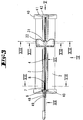
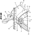
- the frame 2 of the laminate cutter is formed from two essentially mirror-symmetrically arranged hollow bodies which are manufactured using the aluminum extrusion process.
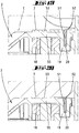
- the two hollow bodies each have a bottom wall 46, an outer wall 43, an inner wall 44 running parallel to the outer wall and a guide wall 45 extending between outer wall 43 and inner wall 44. While the guide wall 45 extends essentially in the vertical direction, the bottom wall 46 extends essentially in the horizontal direction.
- the two housing halves are spaced from one another. The distance between the two housing halves defines a slot 4.
- the slot extends between two web extensions 55, which each form support flanks 18.
- At the two mutually facing ends of the support flanks 18 are stiffening webs 19 which form a pocket that is open at the top.
- the web extensions 55 form a support 3 for a laminate plate 1.
- toothed strips 20 are located in each of the two pockets extending parallel to the immersion slot 4.
- a mechanism (not shown) can be provided in order to displace these toothed racks 20 in the vertical direction.
- the toothed racks 20 are stuck firmly in the grooves 50.
- foam rubber strips 53 are located in recesses 56 of the web extensions 55.
- the upwardly facing surfaces of the foam rubber strips 53 lie in a common plane E, which runs above the tips 52 of the teeth 51 of the toothed strip 20.
- the strips 53 can be compressed. This is done by applying vertical pressure from above. In the unloaded state, the plane E of the upper sides of the strips 53 runs above the tooth tips 52, so that the risk of injury is minimized. Will - as in the Fig.
- a laminate plate 1 is placed on the upper side of the strips 53 and a vertical pressure is exerted downward on the latter, so the upper side of the strips 53 is displaced downwards as a result of a compression of the latter.
- the tips 52 of the teeth 51 can dig into the underside of the plate 1 to be cut.
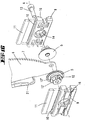
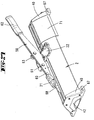
- the teeth of the rack 20 are in a hidden position. They are in a recessed position with respect to the top of the strips 53 forming the support 3. If the cutting knife 6 is removed from the in Fig. 1 The open position shown is displaced clockwise in the direction of the closed position, the point of intersection 8 between the cutting edge 7 and support 3 being displaced in the direction of a stop 22, the toothed racks 20 emerge from the recessed position. You can dig into the underside of the laminate board to fix it.
- the two housing halves are fixed to one another by means of end panels 40, which can be made of plastic. These face claddings also form the feet with which the frame 2 can be set up on a level surface. They protrude beyond the bottom wall 46. In the area of the corner between the bottom wall 46 and the inner wall 44 there is a guide slot 47.
- the two opposite guide slots 47 of the two housing halves form a guide for a drawer 39 designed as a plate. With this drawer 39, the space between the two housing halves can be closed. This gap forms a chip collecting chamber.
- a bottom plate of the drawer 39 is seated on an end plate 42 which, when the drawer is closed, lies in a recess 41 in the front panel.
- There are two drawers 39 which can be inserted from the opposite ends.
- the cutting knife 6 has a bearing opening at its bearing end and a handle at its other end.
- a marginal edge of the cutting knife 6 directly adjoining the bearing end forms a cutting edge 7.
- the opposite edge forms the back of the cutting knife 6 and runs essentially in a straight line.
- the cutting edge 7 extends arcuately in such a way that when the cutting knife 6 is closed, the intersection 8 between the support 3 and the cutting edge 7 moves away from the pivot bearing of the cutting knife 6.
- the arcuate cutting edge 7 has a plurality of spaced apart teeth 17.
- the flanks 17 ′′ of the teeth 17 pointing towards the pivot bearing axis 5 have a steeper angle to the contour line of the cutting edge 7 than the tooth flanks 17 'pointing away from the pivot bearing Teeth 17 one after the other into the surface of the laminate plate 1 when the cutting knife 6 is closed, so as to prevent the laminate plate 1 from slipping during the cut.
- laminate panels can be cut that are wider than the length of the cutting edge 7.
- a laminate panel 1 is placed with one edge against a contact flank of the angle stop 22, the angle stop 22 being at a greater distance from the pivot bearing axis 5 than the length of the Cutting edge 7.
- the illustrated position of the cutting knife 6 generates a first partial cut.
- the cutting knife 6 is located there at the maximum distance from the angle stop 22.
- the cutting knife 6 can be in the in Fig. 1
- the fully open position shown is displaced in the direction of the angle stop 22.
- the user can grip a handle 21 attached to the back of the cutting knife 6.
- the pivot bearing axis 5 is supported by a bearing link 9, which can be moved along the guide walls 45 in the cutting direction.
- the pivot bearing axis 5 consists of two bearing halves which are connected to one another by a connecting screw 13 which extends through the bearing eye of the cutting knife 6.
- the two end sections of the pivot bearing axis 5 that point axially away from one another form eccentric sections 12.
- a first section 12 ' consists of a tangential surface.
- a circular cylinder jacket surface 12 ′′ adjoins this secant surface 12 ′′.
- the circular cylinder jacket surface 12 ′′ is mounted in a bearing opening 14 of a link shell 9 of the bearing link.
- the eccentric section 12 also has a stop 12 "'.
- the link shells 9 each support one of the two eccentric sections 12 pointing away from one another and, following the bearing opening 14, each form pockets 10, in each of which a terminal strip 11 rests.
- the link shells 9 also form dovetail grooves 16 into which dovetail webs 15 engage.
- the dovetail webs 15 run on the outer sides of the guide walls 45, thus point towards one another and extend parallel to the immersion slot 4.
- the clamping strips 11 rest on one side of the eccentric section 12 of the pivot bearing axis 5. On the other hand, the clamping strips 11 rest against the support flanks 18.
- the stop 12 ′′′ rests on a counter-stop of the link shell 9.
- the bearing link 9 can thus be displaced in the direction in which the immersion slot 4 extends. In doing so, it slides along the dovetail webs 15.
- the terminal strip 11 is acted upon by the circumferential section 12 ′′.
- the terminal strip 11 then presses against the support flank 18 so that the displaceability of the bearing link 19 is frictionally blocked.
- the angle stop 22 rests on the support 3 and has an opening 30 through which a screw 23 is inserted.
- the opening 30 is closed with a plug 31 which covers the head of the screw 23.
- the threaded shaft of the screw 23 is screwed into a threaded opening 27 of a clamping link 24.
- the clamping link 24 is located in the space between the two guide walls 45. It has two latching webs 28 which protrude into the immersion slot 4 and can protrude beyond the support 3.
- the clamping link 24 also has two grooves 26 which run parallel to one another and in which threaded pins 25 are inserted as elements which increase friction.
- clamping tongues 29 each protrude from the underside of the clamping link 24 and can be supported on the dovetail webs 15.
- a locking web 28 engages in a locking niche 34 of the angle stop 22.
- the screw 23 is loosened.
- the device has optional stiffening means. These consist of two steel rails 36 extending parallel to one another, which are arranged below the support flank 18 and which limit the displacement path of the bearing link 9.
- the stiffening rails 36 are fastened with several fastening brackets 37 in the space between the guide walls 45.
- the dovetail webs 15 are used for fastening.
- two stiffening rails 36 arranged on different sides of the immersion slot 4 are connected to one another by means of connecting webs 38.
- the connecting webs 38 each connect two retaining brackets 37 to one another.
- a stop buffer 49 is adjacent to this last tooth 48 and is located at the handle end of the cutting knife 6.
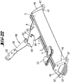
- the exemplary embodiment shown corresponds essentially to the exemplary embodiment described above, but here a foot step 57 is provided on the end plate 42.
- the design of the cutting knife 6 is essential in this exemplary embodiment.
- the handle 62 is placed on the end of the handle arm 59. It consists of two handle scales.
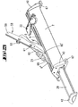
- the actuating lever 58 consists of two essentially identical steel plates which receive the cutting knife 6 made of steel between them.
- the two steel plates forming the actuating lever 58 are connected to one another by a hinge axis 61.
- the hinge axis 61 protrudes through a hinge hole in the cutting knife 6.
- the actuating lever 58 can be pivoted relative to the cutting knife 6 about this hinge axis 61.
- stop means are provided to limit the pivoting angle of the actuating lever 58 with respect to the cutting knife 6. These consist of a stop pin 65 which passes through an arcuate slot 66 of the cutting knife 6. The two ends of the curved slot 66 limit the pivoting angle of the actuating lever 58.
- the second arm 60 of the actuating lever 58 extends approximately at a 180 ° angle to the first arm 59. Both arms 60, 59 are approximately the same length.
- the free end 60 'of the second arm 60 is able to perform a hold-down function for a plate 1 to be cut. Accordingly, the second arm of the actuating lever 58 forms a hold-down arm 60.
- the pivot angle of the actuating lever 58 and the length of the hold-down arm 60 are adjusted to the position of the axis of rotation 61 so that when the cutting knife 6 is opened from a closed position in the direction of an open position, the end 60 'closes the support 3, but at least the upper side of a cutting laminate plate 1 applied downwards.
- the opening of the cutting knife 6 is thus associated not only with a pivoting of the cutting knife 6, but also with a relative pivoting movement of the actuating lever 58 with respect to the cutting knife 6, the free end 60 'of the hold-down arm 60 away from the axis of rotation A of the cutting knife 6 and slides along the top of the cut laminate plate 1, thereby exerting a force on the laminate plate 1 which is directed in the direction of the support 3.
- a locking device 63 is provided which consists of a threaded pin and a rotary knob 63 screwed onto it.
- the cutting knife 6 has an open-edged slot 64 into which the threaded shaft can enter. If the rotary knob 63 is tightened in this position, the pivotability of the actuating lever 58 is blocked, since the cutting knife 6 is clamped between the two steel plates of the actuating lever 58.
- the function of the hold-down device is as follows: If a multiple cut is required to cut a wide laminate board 1, the cutting knife 6 must be swiveled back upwards through the cutting gap in the laminate board 1 after each cut. Since the walls of the cutting gap adhere to the broad side surface of the cutting knife 6 with a friction fit, there is a tendency to lift the laminate sheet 1 when the cutting knife 6 is opened. With the locking device 63 released, however, a torque is exerted on the actuating lever 58 when the handle arm 59 is lifted, since the latter can be pivoted easily about the axis of rotation 61. The hold-down arm 60 inclines downward until its end 60 ′ comes into contact with the upper side of the laminate board 1.
- the end 60 ' is then supported on the upper side of the laminate plate 1 and forms a pivot point about which the actuating lever 58 then rotates when the handle 62 is pulled further upwards.
- the cutting knife 6 is then pulled out of the cut slot, a hold-down force being exerted on the laminate board 1 at the same time via the ends 60 '.
- either the cutting knife 6 is displaced in the direction of the angle stop 22 or the laminate sheet 1 to be cut is displaced in the direction of the cutting knife 6. If the handle 62 is then loaded again in the downward direction, the actuating lever 58 first swivels into its stop position in which either the stop pin 65 hits the upper end of the curved slot 66 or the threaded shaft hits the bottom of the open-edged slot 64. Once this pivoting end position has been reached, a torque can be applied to the cutting knife 6 via the handle arm 59 and its rigid coupling with the cutting knife 6, so that the next cut can be made.
- the plate forms a drawer 39 for receiving chips.
- the plate is not divided into two parts. A single plate extending over the entire length of the frame 2 is provided.
- the two end panels 40 closing the ends of the two parallel hollow profiles of the frame 2 form end caps which, with their underside, form a standing surface 78 with which the laminate cutter can be mounted on a substrate.
- Wings protrude from the end caps 40 on both sides, each of which is provided with a fastening bore 67. Fastening screws can be screwed into these fastening bores 67 in order to permanently fasten the frame to a worktop.
- the illustrated embodiment has only one drawer 39, with which the cavity formed below the immersion slot 4 is closed.
- the drawer 39 essentially consists of a sheet metal strip which has an end plate 42 at its end.
- the end plate 42 forms a handle with which the drawer 39 can be pushed back and forth in a guide.
- the cutting edge 7 of the cutting knife 6 also forms fine teeth in this exemplary embodiment. These are teeth with a tooth height of around 1.5 mm and a pitch of 3 mm. This toothing forms the chest 6 'of the cutting knife.
- the breast 6 ' runs on a contour line which is designed in the shape of an arc.
- the edge of the cutting knife opposite the breast 6 ' forms its back 6 ′′. The latter runs essentially in a straight line and carries a plastic handle 21.
- a zone of reduced cross-section is located between the plastic handle 21 and the pivot bearing axis 5.
- This zone of reduced cross-section is formed by two broad side recesses 68. These are groove-like depressions 68.
- the two grooves 68 which are only a few tenths of a millimeter deep, run parallel to one another and are assigned to the broad broad sides of the cutting knife 6 pointing away from one another.
- the two grooves 68 have a lower step 70 and an upper step 69, which each run parallel to one another.
- the steps 69, 70 shown in the fully open position of the cutting knife 6 run parallel to the support 3. While the groove runs in the horizontal direction in this open position, the back 6 ′′ of the cutting knife 6 runs in the vertical direction Support 3.
- the upper step 69 of the recess 68 lies above the support 3. The distance between the upper step 69 and the support 3 is greater than the material thickness of the plate to be cut.
- a porous plate for example a laminate plate
- the plate must be cut in several, consecutive cuts.
- a first cut is made, which extends only over part of the width of the laminate board. This is done by pivoting the cutting knife 6 from an open position in a closed position. Then the cutting knife must be swiveled out of the partial cut again. This takes place with the aid of the hold-down device 60 already described above and its hold-down function surface 60 '.
- the cutting knife 6 is in the Figures 25 and 26th shown fully open position pivoted.
- the stop pin 65 strikes one end of the arcuate slot 66, as shown in FIG Fig. 25 is shown.
- the zone 68 with reduced cross-section runs in the horizontal direction directly above the support 3.
- the workpiece lying on the support 3 can now be moved further or it can Cutting knife 6 are displaced in the direction of the stop 22.
- This displacement is easy because only the area 68 of reduced cross-section is moved through the slot in the laminate plate 1.
- the bottom of the recesses 68 has a small distance from the walls of the cut gap in the laminate board 1, so that a reduction in sliding friction takes place.
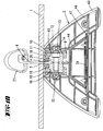
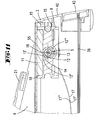
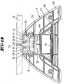
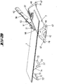
- FIGS. 27 and 28 show a support frame 71 clipped onto the frame.
- the latter consists of a U- or V-shaped molded part, the inner cross-sectional contour of which corresponds approximately to the outer cross-sectional contour of the frame 2.
- the support frame 71 has a head section 75 which rests on the support 3. In the middle, the head section 75 has an indentation 76 which protrudes into the immersion slot 4.
- Middle sections 74 protrude on both sides of the head section 75 and follow the outer wall 72 of the two hollow bodies that form the frame 2.
- a foot section 73 adjoins each of the two middle sections 74. The foot sections 73 run essentially in the vertical direction and parallel to one another.
- the support frame 71 has inwardly projecting locking lips 77 which catch the hollow bodies forming the frame 2 in a locking manner. With these locking lips 77 a temporary fixation of the support frame 71 on the frame 2 is possible.
- the laminate cutter can be used with the support frame 71 clipped onto the frame 2. This is because the support block 71 does not lie in the cutting area of the cutting knife 6.
- the support block 71 can be removed from the frame 2 in order to serve as a support for a laminate plate 1, as it is Fig. 29 indicates. Since the distance between the standing surface 78 and the support 3 and the edge 73 ′ and the head section 75 is the same, the laminate plate 1 runs parallel to the mounting surface of the frame 2 and the support frame 71.
Landscapes
- Engineering & Computer Science (AREA)
- Architecture (AREA)
- Life Sciences & Earth Sciences (AREA)
- Forests & Forestry (AREA)
- Mechanical Engineering (AREA)
- Civil Engineering (AREA)
- Structural Engineering (AREA)
- Knives (AREA)
- Details Of Cutting Devices (AREA)
Claims (15)
- Dispositif, destiné à couper un panneau (1) poreux, majoritairement rigide en flexion, notamment un panneau de sol laminé, comprenant un châssis (2), un support (3) pour le panneau (1) formé par le châssis (2) une fente d'immersion (4) associée au support (3) et une lame de coupe (6) fixée de manière pivotante sur le châssis (2) en étant susceptible de pivoter autour d'un axe de pivotement (A) formé par un palier pivotant (5, 9) de telle sorte que lors du pivotement de la lame de coupe (6) d'une position ouverte dans une position fermée, son tranchant (7) plonge dans la fente d'immersion (4), pendant la fermeture de la lame de coupe (6), un point d'intersection (8) entre le support (3) et le tranchant (7) situé dans le plan de pivotement migrant du côté du support (3) proximal du palier pivotant (5, 9) vers le côté du support (3) distal du palier pivotant (5, 9), caractérisé en ce que le châssis (2) comporte deux corps creux, qui par leurs parois (43, 44, 45, 46) forment des profilés creux, lesquels sont reliés avec des habillages de face frontale (40), de telle sorte que la fente d'immersion (4) se situe entre les corps creux.
- Dispositif selon la revendication 1, caractérisé en ce que les corps creux sont placés en symétrie spéculaire l'un par rapport à l'autre et forment des profilés creux s'écoulant à la parallèle l'une de l'autre.
- Dispositif selon l'une quelconque des revendications précédentes, caractérisé en ce que les habillages de face frontale (40) ferment les extrémités des deux profilés creux du châssis (2) s'écoulant à la parallèle l'un de l'autre.
- Dispositif selon la revendication 2, caractérisé en ce que les habillages de face frontale (40) forment des capuchons d'extrémité, qui par leur face inférieure forment une surface d'assise (78) permettant de poser le dispositif sur un sol.
- Dispositif selon l'une quelconque des revendications précédentes, caractérisé en ce que les corps creux sont des pièces en aluminium extrudé.
- Dispositif selon l'une quelconque des revendications précédentes, caractérisé en ce que les deux corps creux comportent chacun une paroi de fond inférieur (46), une paroi extérieure (43) et une paroi intérieure (44) s'écoulant à la parallèle de la paroi extérieure (43), la paroi de fond inférieur (46) s'étendant sensiblement dans la direction horizontale.
- Dispositif selon l'une quelconque des revendications précédentes, caractérisé en ce que les deux moitiés de boîtier formées par les corps creux sont écartées l'une de l'autre, l'écart entre les deux moitiés de boîtier définissant la fente d'immersion (4).
- Dispositif selon l'une quelconque des revendications 3 à 7, caractérisé en ce que les pieds formés par les habillages de face frontale saillissent par-dessus la paroi de fond inférieur (46).
- Dispositif selon l'une quelconque des revendications précédentes, caractérisé par un support d'appui (71), susceptible d'être fixé temporairement sur le châssis (2), pourvu d'une partie basse (73) et d'une partie haute (75).
- Dispositif selon la revendication 9, caractérisé en ce que le support d'appui (71) comporte deux segments médians (74) saillant à partir de la partie haute (75), qui lorsqu'ils sont temporairement reliés avec le châssis (2), sont adjacents à la paroi latérale (72) du châssis (2).
- Dispositif selon l'une quelconque des revendications 9 ou 10, caractérisé en ce que le support d'appui (71) accroche par le bas le châssis (2) avec des lèvres d'enclenchement (77) saillant vers l'intérieur.
- Dispositif selon l'une quelconque des revendications 9 à 11, caractérisé en ce que le contour de la section transversale intérieure du support d'appui (71) correspond approximativement au contour de la section transversale extérieure du châssis (2), le support d'appui (71) détenant une partie haute (75) qui repose sur le support (3).
- Dispositif selon l'une quelconque des revendications 9 à 12, caractérisé en ce que la partie haute (75) comporte au centre une empreinte (76) qui saillit à l'intérieur de la fente d'immersion (4).
- Dispositif selon l'une quelconque des revendications 9 à 13, caractérisé en ce que le dispositif est utilisable avec le support d'appui (71) porté par le châssis (2), le support d'appui (71) ne se situant pas dans la zone de coupe de la lame de coupe (6).
- Dispositif selon l'une quelconque des revendications précédentes, caractérisé en ce dans la région de la zone de support sont prévues des dents, lesquelles sont associées notamment à une baguette dentée, laquelle s'étend notamment dans une rainure de logement, de préférence de part et d'autre de la fente d'immersion étant prévues des rainures de logement qui sont équipées chacune dans une baguette dentée.
Applications Claiming Priority (3)
| Application Number | Priority Date | Filing Date | Title |
|---|---|---|---|
| DE102009003490A DE102009003490A1 (de) | 2009-02-16 | 2009-02-16 | Vorrichtung zum Schneiden von Laminat-Fußbodenplatten |
| EP10704558.5A EP2396151B1 (fr) | 2009-02-16 | 2010-02-16 | Dispositif pour la coupe de plates de parquet laminé |
| PCT/EP2010/051919 WO2010092183A2 (fr) | 2009-02-16 | 2010-02-16 | Dispositif de coupe de plaques de revêtement de sol colaminé |
Related Parent Applications (2)
| Application Number | Title | Priority Date | Filing Date |
|---|---|---|---|
| EP10704558.5 Division | 2010-02-16 | ||
| EP10704558.5A Division EP2396151B1 (fr) | 2009-02-16 | 2010-02-16 | Dispositif pour la coupe de plates de parquet laminé |
Publications (3)
| Publication Number | Publication Date |
|---|---|
| EP2617538A1 EP2617538A1 (fr) | 2013-07-24 |
| EP2617538B1 EP2617538B1 (fr) | 2014-07-02 |
| EP2617538B2 true EP2617538B2 (fr) | 2021-12-08 |
Family
ID=42136038
Family Applications (3)
| Application Number | Title | Priority Date | Filing Date |
|---|---|---|---|
| EP10704558.5A Active EP2396151B1 (fr) | 2009-02-16 | 2010-02-16 | Dispositif pour la coupe de plates de parquet laminé |
| EP13158871.7A Active EP2636494B1 (fr) | 2009-02-16 | 2010-02-16 | Dispositif de coupe de plaques de plancher laminées |
| EP13164222.5A Active EP2617538B2 (fr) | 2009-02-16 | 2010-02-16 | Dispositif de coupe de plaques de plancher laminées |
Family Applications Before (2)
| Application Number | Title | Priority Date | Filing Date |
|---|---|---|---|
| EP10704558.5A Active EP2396151B1 (fr) | 2009-02-16 | 2010-02-16 | Dispositif pour la coupe de plates de parquet laminé |
| EP13158871.7A Active EP2636494B1 (fr) | 2009-02-16 | 2010-02-16 | Dispositif de coupe de plaques de plancher laminées |
Country Status (4)
| Country | Link |
|---|---|
| EP (3) | EP2396151B1 (fr) |
| DE (2) | DE102009003490A1 (fr) |
| ES (2) | ES2491819T5 (fr) |
| WO (1) | WO2010092183A2 (fr) |
Families Citing this family (11)
| Publication number | Priority date | Publication date | Assignee | Title |
|---|---|---|---|---|
| DE102010016459A1 (de) | 2010-04-15 | 2011-10-20 | Wolfcraft Gmbh | Vorrichtung zum Schneiden insbesondere von Laminat-Fußbodenplatten insbesondere mit einer verzahnten Schneidkante |
| DE102009043992A1 (de) | 2009-07-17 | 2011-01-20 | Wolfcraft Gmbh | Vorrichtung zum Schneiden insbesondere von Laminat-Fußbodenplatten insbesondere mit einer verzahnten Schneidkante |
| DE102010060244B4 (de) | 2010-10-29 | 2025-08-14 | Wolfcraft Gmbh | Vorrichtung zum Schneiden von biegesteifen Platten |
| DE102011050665A1 (de) | 2011-05-27 | 2012-11-29 | Wolfcraft Gmbh | Schneidevorrichtung für Fußbodenbeläge aus Kunststoff, Gummi oder einem anderen zähen oder elastischen Werkstoff |
| DE102011050664A1 (de) | 2011-05-27 | 2012-11-29 | Wolfcraft Gmbh | Schneidevorrichtung für Fußbodenbeläge aus Kunststoff, Gummi oder einem anderen zähen oder elastischen Werkstoff |
| CN102806587B (zh) * | 2012-07-05 | 2015-04-22 | 杭州一楠五金工具有限公司 | 复合木板切割机专用刀板 |
| CN102806588B (zh) * | 2012-07-05 | 2015-04-22 | 杭州一楠五金工具有限公司 | 复合木板切割机 |
| DE202013009304U1 (de) | 2013-10-22 | 2014-02-12 | Meister Werkzeuge Gmbh | Handbetätigte Vorrichtung zum Zerteilen von Platten eines Fußbodenbelags |
| FR3016312B1 (fr) * | 2014-01-13 | 2016-01-22 | Grehal Pierre Ets Cie Sa | Butee amovible pour un outil de coupe de plaque et outil de coupe comportant une telle butee amovible. |
| FR3068905B1 (fr) * | 2017-07-16 | 2019-08-09 | Etablissements Pierre Grehal Et Cie Sa | Outil de decoupe de plaque notamment en materiau reconstitue. |
| DE102019108632A1 (de) | 2019-04-02 | 2020-10-08 | Wolfcraft Gmbh | Hebelübersetzte Schneidvorrichtung |
Citations (1)
| Publication number | Priority date | Publication date | Assignee | Title |
|---|---|---|---|---|
| EP2098342A1 (fr) † | 2008-03-07 | 2009-09-09 | D-Cut Products INC. | Outil de coupe |
Family Cites Families (27)
| Publication number | Priority date | Publication date | Assignee | Title |
|---|---|---|---|---|
| DE53249C (de) * | A. MAY in Frankfurt a. M., Palmstr. 5 | Beschneide-Apparat | ||
| FR575749A (fr) | 1924-01-11 | 1924-08-05 | Appareil à couper les baguettes pour fils électriques | |
| FR612747A (fr) | 1926-03-13 | 1926-10-29 | Cisaille pour plaques de fibro-ciment, ardoises et autres matériaux analogues | |
| US1730474A (en) * | 1928-04-21 | 1929-10-08 | Oller Emmett Elmer | Tin-cutting device |
| DE681039C (de) * | 1937-12-09 | 1939-09-13 | Burger Eisenwerke G M B H | Einrichtung zum Schneiden von harten und sproeden Kunststeinplatten o. dgl. |
| US2168704A (en) * | 1938-09-02 | 1939-08-08 | Forshey Thomas Henry | Metal cutting and forming machine |
| GB506375A (en) * | 1938-11-23 | 1939-05-26 | Hugh Lucas Parsons | A cutting and punching tool for slate and like materials |
| FR847014A (fr) | 1938-12-05 | 1939-10-02 | Outils tranchants | |
| US2372784A (en) * | 1944-01-13 | 1945-04-03 | Bollie M Jansen | Cutting apparatus |
| US2435559A (en) * | 1945-08-24 | 1948-02-03 | Harvey M Pushker | Trimming board |
| US2496018A (en) * | 1945-12-13 | 1950-01-31 | Oscar H Pearson | Shear |
| US2643720A (en) * | 1948-05-27 | 1953-06-30 | Johns Manville | Apparatus for cutting sheet material |
| FR1016823A (fr) | 1950-04-28 | 1952-11-24 | Nouvelle cisaille perfectionnée | |
| FR60493E (fr) * | 1950-08-17 | 1954-11-03 | Nouvelle cisaille perfectionnée | |
| GB693702A (en) * | 1950-08-21 | 1953-07-08 | Harry Freeman | Improvements relating to machines for cutting sheet material such as asbestos cementsheeting |
| FR1061929A (fr) * | 1952-05-12 | 1954-04-16 | Nouvelle cisaille pour matériaux ondulés | |
| US2779325A (en) * | 1954-12-20 | 1957-01-29 | Texas Foundries Inc | Shingle cutter |
| US3362070A (en) * | 1966-06-27 | 1968-01-09 | W P B Ind Products Co Inc | Steel siding shear |
| DE2262862A1 (de) * | 1972-12-22 | 1974-07-18 | Hamme | Handgeraet, insbesondere fuer den haushalt |
| DE8136527U1 (de) * | 1981-12-15 | 1982-05-13 | Jöcker, Eduard, 5600 Wuppertal | Fliesenschneidgerät |
| DD297043A7 (de) * | 1989-08-07 | 1992-01-02 | Energiewerke Schwarze Pumpe Ag,De | Vorrichtung zum schneiden von foerdergurten, vorzugsweise von stahlseilfoerdergurten |
| US5038477A (en) * | 1990-06-26 | 1991-08-13 | Parrow Harold A | Universal siding cutting |
| FR2882955B1 (fr) * | 2005-03-10 | 2008-10-17 | Grehal Pierre Ets Cie Sa | Outil de coupe pour decouper une plaque |
| US20070137453A1 (en) | 2005-07-06 | 2007-06-21 | Etablissements Pierre Grehat Et Cie Sa | Cutting tool for cutting a sheet |
| WO2008049976A1 (fr) * | 2006-10-23 | 2008-05-02 | Etablissements Pierre Grehal Et Cie S.A. | Lame pour un outil de coupe pour découper une plaque et outil comportant une telle lame |
| DE202008007769U1 (de) * | 2008-06-11 | 2008-08-14 | Schwelling, Hermann | Schneidegerät |
| DE202008015612U1 (de) * | 2008-11-25 | 2009-03-05 | Grahmann, Joachim | Gerät zum Zuschneiden von Paneelen und Verbundplatten wie Bodenbeläge aus Laminat |
-
2009
- 2009-02-16 DE DE102009003490A patent/DE102009003490A1/de active Pending
-
2010
- 2010-02-16 EP EP10704558.5A patent/EP2396151B1/fr active Active
- 2010-02-16 EP EP13158871.7A patent/EP2636494B1/fr active Active
- 2010-02-16 ES ES13164222T patent/ES2491819T5/es active Active
- 2010-02-16 DE DE202010018003U patent/DE202010018003U1/de not_active Expired - Lifetime
- 2010-02-16 ES ES13158871.7T patent/ES2535383T3/es active Active
- 2010-02-16 WO PCT/EP2010/051919 patent/WO2010092183A2/fr not_active Ceased
- 2010-02-16 EP EP13164222.5A patent/EP2617538B2/fr active Active
Patent Citations (1)
| Publication number | Priority date | Publication date | Assignee | Title |
|---|---|---|---|---|
| EP2098342A1 (fr) † | 2008-03-07 | 2009-09-09 | D-Cut Products INC. | Outil de coupe |
Also Published As
| Publication number | Publication date |
|---|---|
| EP2396151A2 (fr) | 2011-12-21 |
| ES2491819T3 (es) | 2014-09-08 |
| EP2636494A2 (fr) | 2013-09-11 |
| EP2636494B1 (fr) | 2015-03-18 |
| DE202010018003U1 (de) | 2013-09-12 |
| ES2535383T3 (es) | 2015-05-08 |
| WO2010092183A2 (fr) | 2010-08-19 |
| WO2010092183A3 (fr) | 2010-12-23 |
| EP2636494A3 (fr) | 2013-12-04 |
| ES2491819T5 (es) | 2022-04-11 |
| EP2617538A1 (fr) | 2013-07-24 |
| EP2617538B1 (fr) | 2014-07-02 |
| DE102009003490A1 (de) | 2010-08-19 |
| EP2396151B1 (fr) | 2013-05-29 |
Similar Documents
| Publication | Publication Date | Title |
|---|---|---|
| EP2617538B2 (fr) | Dispositif de coupe de plaques de plancher laminées | |
| DE69935744T2 (de) | Tischsäge | |
| EP2484473B1 (fr) | Dispositif de sciage fonctionnant de manière stationnaire et mobile | |
| EP3138674B1 (fr) | Dispositif de coupe en onglet | |
| DE3043334A1 (de) | Scharnierarm mit befestigungsplatte | |
| EP2949844B1 (fr) | Agencement de bande pour portes, fenêtres ou analogues, doté d'un dispositif de réglage de jeu de joint | |
| DE202007011076U1 (de) | Bandanordnung mit Führungsprofil | |
| DE102008054368A1 (de) | Roboterzelle | |
| DE202018102164U1 (de) | Aufbau einer Vorrichtung zum Heben und/oder Senken von Stuhllehnen | |
| DE102013105257A1 (de) | Doppelkeil zum Rahmensetzen | |
| EP4187050B1 (fr) | Dispositif de fixation pour un dispositif de fermeture de bâtiment, procédé de fabrication du dispositif de fixation ainsi que dispositif de fermeture de bâtiment | |
| EP1794053B1 (fr) | Dispositif de fixation d'un objet sur un rail | |
| EP0445363A1 (fr) | Dispositif de fraisage ou perçage | |
| DE4313134C1 (de) | Amboß-Gehrungsschere zum Schneiden von Dichtungsprofilen | |
| EP1659242B1 (fr) | Dispositif de retenue de porte | |
| EP3533944B1 (fr) | Construction de superstructure pour une évacuation d'eau à suspension du rabat de recouvrement réglable | |
| EP3640425A1 (fr) | Dispositif de réception d'une plaque de garde-corps | |
| DE20120238U1 (de) | Montageplatte zur verstellbaren Halterung von Möbelscharnieren am Korpus von Möbelstücken | |
| EP2712717A1 (fr) | Dispositif de découpe de pièces, notamment machine à couper les carreaux doté d'un élément fonctionnel fixé de façon mobile à une plaque de base | |
| DE8905851U1 (de) | Fräs- oder Bohrvorrichtung | |
| EP2162267B1 (fr) | Dispositif de fixation d'une règle de butée sur la table de machine d'une scie circulaire de table | |
| DE20108850U1 (de) | Betätigungsvorrichtung für ein Lamellenfenster | |
| DE10209135A1 (de) | Laufwerkanordnung für Schiebetür | |
| DE8914809U1 (de) | Messerkopf | |
| DE20009747U1 (de) | Tischkreissäge |
Legal Events
| Date | Code | Title | Description |
|---|---|---|---|
| PUAI | Public reference made under article 153(3) epc to a published international application that has entered the european phase |
Free format text: ORIGINAL CODE: 0009012 |
|
| AC | Divisional application: reference to earlier application |
Ref document number: 2396151 Country of ref document: EP Kind code of ref document: P |
|
| AK | Designated contracting states |
Kind code of ref document: A1 Designated state(s): AT BE BG CH CY CZ DE DK EE ES FI FR GB GR HR HU IE IS IT LI LT LU LV MC MK MT NL NO PL PT RO SE SI SK SM TR |
|
| 17P | Request for examination filed |
Effective date: 20130808 |
|
| RBV | Designated contracting states (corrected) |
Designated state(s): AT BE BG CH CY CZ DE DK EE ES FI FR GB GR HR HU IE IS IT LI LT LU LV MC MK MT NL NO PL PT RO SE SI SK SM TR |
|
| 17Q | First examination report despatched |
Effective date: 20131021 |
|
| GRAP | Despatch of communication of intention to grant a patent |
Free format text: ORIGINAL CODE: EPIDOSNIGR1 |
|
| INTG | Intention to grant announced |
Effective date: 20140128 |
|
| GRAS | Grant fee paid |
Free format text: ORIGINAL CODE: EPIDOSNIGR3 |
|
| GRAA | (expected) grant |
Free format text: ORIGINAL CODE: 0009210 |
|
| AC | Divisional application: reference to earlier application |
Ref document number: 2396151 Country of ref document: EP Kind code of ref document: P |
|
| AK | Designated contracting states |
Kind code of ref document: B1 Designated state(s): AT BE BG CH CY CZ DE DK EE ES FI FR GB GR HR HU IE IS IT LI LT LU LV MC MK MT NL NO PL PT RO SE SI SK SM TR |
|
| REG | Reference to a national code |
Ref country code: GB Ref legal event code: FG4D Free format text: NOT ENGLISH |
|
| REG | Reference to a national code |
Ref country code: CH Ref legal event code: EP Ref country code: CH Ref legal event code: NV Representative=s name: R. A. EGLI AND CO. PATENTANWAELTE, CH Ref country code: AT Ref legal event code: REF Ref document number: 675665 Country of ref document: AT Kind code of ref document: T Effective date: 20140715 |
|
| REG | Reference to a national code |
Ref country code: IE Ref legal event code: FG4D Free format text: LANGUAGE OF EP DOCUMENT: GERMAN |
|
| REG | Reference to a national code |
Ref country code: DE Ref legal event code: R096 Ref document number: 502010007405 Country of ref document: DE Effective date: 20140814 |
|
| REG | Reference to a national code |
Ref country code: ES Ref legal event code: FG2A Ref document number: 2491819 Country of ref document: ES Kind code of ref document: T3 Effective date: 20140908 |
|
| REG | Reference to a national code |
Ref country code: SE Ref legal event code: TRGR |
|
| REG | Reference to a national code |
Ref country code: NL Ref legal event code: T3 |
|
| REG | Reference to a national code |
Ref country code: DE Ref legal event code: R026 Ref document number: 502010007405 Country of ref document: DE |
|
| PLBI | Opposition filed |
Free format text: ORIGINAL CODE: 0009260 |
|
| 26 | Opposition filed |
Opponent name: D CUT PRODUCTS, INC. Effective date: 20141023 |
|
| REG | Reference to a national code |
Ref country code: LT Ref legal event code: MG4D |
|
| REG | Reference to a national code |
Ref country code: DE Ref legal event code: R026 Ref document number: 502010007405 Country of ref document: DE Effective date: 20141023 |
|
| PG25 | Lapsed in a contracting state [announced via postgrant information from national office to epo] |
Ref country code: PT Free format text: LAPSE BECAUSE OF FAILURE TO SUBMIT A TRANSLATION OF THE DESCRIPTION OR TO PAY THE FEE WITHIN THE PRESCRIBED TIME-LIMIT Effective date: 20141103 Ref country code: NO Free format text: LAPSE BECAUSE OF FAILURE TO SUBMIT A TRANSLATION OF THE DESCRIPTION OR TO PAY THE FEE WITHIN THE PRESCRIBED TIME-LIMIT Effective date: 20141002 Ref country code: BG Free format text: LAPSE BECAUSE OF FAILURE TO SUBMIT A TRANSLATION OF THE DESCRIPTION OR TO PAY THE FEE WITHIN THE PRESCRIBED TIME-LIMIT Effective date: 20141002 Ref country code: GR Free format text: LAPSE BECAUSE OF FAILURE TO SUBMIT A TRANSLATION OF THE DESCRIPTION OR TO PAY THE FEE WITHIN THE PRESCRIBED TIME-LIMIT Effective date: 20141003 Ref country code: LT Free format text: LAPSE BECAUSE OF FAILURE TO SUBMIT A TRANSLATION OF THE DESCRIPTION OR TO PAY THE FEE WITHIN THE PRESCRIBED TIME-LIMIT Effective date: 20140702 Ref country code: CZ Free format text: LAPSE BECAUSE OF FAILURE TO SUBMIT A TRANSLATION OF THE DESCRIPTION OR TO PAY THE FEE WITHIN THE PRESCRIBED TIME-LIMIT Effective date: 20140702 |
|
| PG25 | Lapsed in a contracting state [announced via postgrant information from national office to epo] |
Ref country code: CY Free format text: LAPSE BECAUSE OF FAILURE TO SUBMIT A TRANSLATION OF THE DESCRIPTION OR TO PAY THE FEE WITHIN THE PRESCRIBED TIME-LIMIT Effective date: 20140702 Ref country code: LV Free format text: LAPSE BECAUSE OF FAILURE TO SUBMIT A TRANSLATION OF THE DESCRIPTION OR TO PAY THE FEE WITHIN THE PRESCRIBED TIME-LIMIT Effective date: 20140702 Ref country code: IS Free format text: LAPSE BECAUSE OF FAILURE TO SUBMIT A TRANSLATION OF THE DESCRIPTION OR TO PAY THE FEE WITHIN THE PRESCRIBED TIME-LIMIT Effective date: 20141102 Ref country code: PL Free format text: LAPSE BECAUSE OF FAILURE TO SUBMIT A TRANSLATION OF THE DESCRIPTION OR TO PAY THE FEE WITHIN THE PRESCRIBED TIME-LIMIT Effective date: 20140702 Ref country code: HR Free format text: LAPSE BECAUSE OF FAILURE TO SUBMIT A TRANSLATION OF THE DESCRIPTION OR TO PAY THE FEE WITHIN THE PRESCRIBED TIME-LIMIT Effective date: 20140702 |
|
| PG25 | Lapsed in a contracting state [announced via postgrant information from national office to epo] |
Ref country code: SK Free format text: LAPSE BECAUSE OF FAILURE TO SUBMIT A TRANSLATION OF THE DESCRIPTION OR TO PAY THE FEE WITHIN THE PRESCRIBED TIME-LIMIT Effective date: 20140702 Ref country code: RO Free format text: LAPSE BECAUSE OF FAILURE TO SUBMIT A TRANSLATION OF THE DESCRIPTION OR TO PAY THE FEE WITHIN THE PRESCRIBED TIME-LIMIT Effective date: 20140702 Ref country code: DK Free format text: LAPSE BECAUSE OF FAILURE TO SUBMIT A TRANSLATION OF THE DESCRIPTION OR TO PAY THE FEE WITHIN THE PRESCRIBED TIME-LIMIT Effective date: 20140702 Ref country code: EE Free format text: LAPSE BECAUSE OF FAILURE TO SUBMIT A TRANSLATION OF THE DESCRIPTION OR TO PAY THE FEE WITHIN THE PRESCRIBED TIME-LIMIT Effective date: 20140702 |
|
| PLAX | Notice of opposition and request to file observation + time limit sent |
Free format text: ORIGINAL CODE: EPIDOSNOBS2 |
|
| PLBB | Reply of patent proprietor to notice(s) of opposition received |
Free format text: ORIGINAL CODE: EPIDOSNOBS3 |
|
| PG25 | Lapsed in a contracting state [announced via postgrant information from national office to epo] |
Ref country code: BE Free format text: LAPSE BECAUSE OF NON-PAYMENT OF DUE FEES Effective date: 20150228 |
|
| PG25 | Lapsed in a contracting state [announced via postgrant information from national office to epo] |
Ref country code: LU Free format text: LAPSE BECAUSE OF FAILURE TO SUBMIT A TRANSLATION OF THE DESCRIPTION OR TO PAY THE FEE WITHIN THE PRESCRIBED TIME-LIMIT Effective date: 20150216 |
|
| PG25 | Lapsed in a contracting state [announced via postgrant information from national office to epo] |
Ref country code: MC Free format text: LAPSE BECAUSE OF FAILURE TO SUBMIT A TRANSLATION OF THE DESCRIPTION OR TO PAY THE FEE WITHIN THE PRESCRIBED TIME-LIMIT Effective date: 20140702 |
|
| REG | Reference to a national code |
Ref country code: IE Ref legal event code: MM4A |
|
| PG25 | Lapsed in a contracting state [announced via postgrant information from national office to epo] |
Ref country code: SI Free format text: LAPSE BECAUSE OF FAILURE TO SUBMIT A TRANSLATION OF THE DESCRIPTION OR TO PAY THE FEE WITHIN THE PRESCRIBED TIME-LIMIT Effective date: 20140702 |
|
| PG25 | Lapsed in a contracting state [announced via postgrant information from national office to epo] |
Ref country code: IE Free format text: LAPSE BECAUSE OF NON-PAYMENT OF DUE FEES Effective date: 20150216 |
|
| REG | Reference to a national code |
Ref country code: FR Ref legal event code: PLFP Year of fee payment: 7 |
|
| APBM | Appeal reference recorded |
Free format text: ORIGINAL CODE: EPIDOSNREFNO |
|
| APBP | Date of receipt of notice of appeal recorded |
Free format text: ORIGINAL CODE: EPIDOSNNOA2O |
|
| APAH | Appeal reference modified |
Free format text: ORIGINAL CODE: EPIDOSCREFNO |
|
| APBM | Appeal reference recorded |
Free format text: ORIGINAL CODE: EPIDOSNREFNO |
|
| APBP | Date of receipt of notice of appeal recorded |
Free format text: ORIGINAL CODE: EPIDOSNNOA2O |
|
| PG25 | Lapsed in a contracting state [announced via postgrant information from national office to epo] |
Ref country code: MT Free format text: LAPSE BECAUSE OF FAILURE TO SUBMIT A TRANSLATION OF THE DESCRIPTION OR TO PAY THE FEE WITHIN THE PRESCRIBED TIME-LIMIT Effective date: 20140702 |
|
| APBQ | Date of receipt of statement of grounds of appeal recorded |
Free format text: ORIGINAL CODE: EPIDOSNNOA3O |
|
| APBQ | Date of receipt of statement of grounds of appeal recorded |
Free format text: ORIGINAL CODE: EPIDOSNNOA3O |
|
| REG | Reference to a national code |
Ref country code: FR Ref legal event code: PLFP Year of fee payment: 8 |
|
| PG25 | Lapsed in a contracting state [announced via postgrant information from national office to epo] |
Ref country code: HU Free format text: LAPSE BECAUSE OF FAILURE TO SUBMIT A TRANSLATION OF THE DESCRIPTION OR TO PAY THE FEE WITHIN THE PRESCRIBED TIME-LIMIT; INVALID AB INITIO Effective date: 20100216 Ref country code: SM Free format text: LAPSE BECAUSE OF FAILURE TO SUBMIT A TRANSLATION OF THE DESCRIPTION OR TO PAY THE FEE WITHIN THE PRESCRIBED TIME-LIMIT Effective date: 20140702 |
|
| PG25 | Lapsed in a contracting state [announced via postgrant information from national office to epo] |
Ref country code: TR Free format text: LAPSE BECAUSE OF FAILURE TO SUBMIT A TRANSLATION OF THE DESCRIPTION OR TO PAY THE FEE WITHIN THE PRESCRIBED TIME-LIMIT Effective date: 20140702 |
|
| REG | Reference to a national code |
Ref country code: FR Ref legal event code: PLFP Year of fee payment: 9 |
|
| PG25 | Lapsed in a contracting state [announced via postgrant information from national office to epo] |
Ref country code: MK Free format text: LAPSE BECAUSE OF FAILURE TO SUBMIT A TRANSLATION OF THE DESCRIPTION OR TO PAY THE FEE WITHIN THE PRESCRIBED TIME-LIMIT Effective date: 20140702 |
|
| PLAB | Opposition data, opponent's data or that of the opponent's representative modified |
Free format text: ORIGINAL CODE: 0009299OPPO |
|
| PLAB | Opposition data, opponent's data or that of the opponent's representative modified |
Free format text: ORIGINAL CODE: 0009299OPPO |
|
| R26 | Opposition filed (corrected) |
Opponent name: D CUT PRODUCTS, INC. Effective date: 20141023 |
|
| R26 | Opposition filed (corrected) |
Opponent name: D CUT PRODUCTS, INC. Effective date: 20141023 |
|
| PLAB | Opposition data, opponent's data or that of the opponent's representative modified |
Free format text: ORIGINAL CODE: 0009299OPPO |
|
| R26 | Opposition filed (corrected) |
Opponent name: D CUT PRODUCTS, INC. Effective date: 20141023 |
|
| PLBP | Opposition withdrawn |
Free format text: ORIGINAL CODE: 0009264 |
|
| APBU | Appeal procedure closed |
Free format text: ORIGINAL CODE: EPIDOSNNOA9O |
|
| PUAH | Patent maintained in amended form |
Free format text: ORIGINAL CODE: 0009272 |
|
| STAA | Information on the status of an ep patent application or granted ep patent |
Free format text: STATUS: PATENT MAINTAINED AS AMENDED |
|
| 27A | Patent maintained in amended form |
Effective date: 20211208 |
|
| AK | Designated contracting states |
Kind code of ref document: B2 Designated state(s): AT BE BG CH CY CZ DE DK EE ES FI FR GB GR HR HU IE IS IT LI LT LU LV MC MK MT NL NO PL PT RO SE SI SK SM TR |
|
| REG | Reference to a national code |
Ref country code: DE Ref legal event code: R102 Ref document number: 502010007405 Country of ref document: DE |
|
| REG | Reference to a national code |
Ref country code: NL Ref legal event code: FP |
|
| REG | Reference to a national code |
Ref country code: SE Ref legal event code: RPEO |
|
| REG | Reference to a national code |
Ref country code: ES Ref legal event code: DC2A Ref document number: 2491819 Country of ref document: ES Kind code of ref document: T5 Effective date: 20220411 |
|
| P01 | Opt-out of the competence of the unified patent court (upc) registered |
Effective date: 20230513 |
|
| REG | Reference to a national code |
Ref country code: CH Ref legal event code: U11 Free format text: ST27 STATUS EVENT CODE: U-0-0-U10-U11 (AS PROVIDED BY THE NATIONAL OFFICE) Effective date: 20260301 |
|
| PGFP | Annual fee paid to national office [announced via postgrant information from national office to epo] |
Ref country code: NL Payment date: 20260218 Year of fee payment: 17 |
|
| PGFP | Annual fee paid to national office [announced via postgrant information from national office to epo] |
Ref country code: SE Payment date: 20260218 Year of fee payment: 17 |
|
| PGFP | Annual fee paid to national office [announced via postgrant information from national office to epo] |
Ref country code: GB Payment date: 20260218 Year of fee payment: 17 |
|
| PGFP | Annual fee paid to national office [announced via postgrant information from national office to epo] |
Ref country code: ES Payment date: 20260310 Year of fee payment: 17 |
|
| PGFP | Annual fee paid to national office [announced via postgrant information from national office to epo] |
Ref country code: DE Payment date: 20250401 Year of fee payment: 17 |
|
| PGFP | Annual fee paid to national office [announced via postgrant information from national office to epo] |
Ref country code: AT Payment date: 20260218 Year of fee payment: 17 |
|
| PGFP | Annual fee paid to national office [announced via postgrant information from national office to epo] |
Ref country code: FI Payment date: 20260218 Year of fee payment: 17 Ref country code: IT Payment date: 20260225 Year of fee payment: 17 |
|
| PGFP | Annual fee paid to national office [announced via postgrant information from national office to epo] |
Ref country code: FR Payment date: 20260218 Year of fee payment: 17 |
|
| PGFP | Annual fee paid to national office [announced via postgrant information from national office to epo] |
Ref country code: CH Payment date: 20260301 Year of fee payment: 17 |