EP2716250A2 - Dispositifs médicaux pour le traitement thermique de tissus - Google Patents
Dispositifs médicaux pour le traitement thermique de tissus Download PDFInfo
- Publication number
- EP2716250A2 EP2716250A2 EP13187073.5A EP13187073A EP2716250A2 EP 2716250 A2 EP2716250 A2 EP 2716250A2 EP 13187073 A EP13187073 A EP 13187073A EP 2716250 A2 EP2716250 A2 EP 2716250A2
- Authority
- EP
- European Patent Office
- Prior art keywords
- tissue
- solid state
- heating element
- heat
- state heating
- Prior art date
- Legal status (The legal status is an assumption and is not a legal conclusion. Google has not performed a legal analysis and makes no representation as to the accuracy of the status listed.)
- Withdrawn
Links
- 238000010438 heat treatment Methods 0.000 claims abstract description 136
- 239000007787 solid Substances 0.000 claims abstract description 118
- 239000012636 effector Substances 0.000 claims description 58
- 230000020169 heat generation Effects 0.000 claims description 6
- 230000001419 dependent effect Effects 0.000 claims description 2
- 239000000758 substrate Substances 0.000 description 28
- 239000003990 capacitor Substances 0.000 description 18
- 238000000034 method Methods 0.000 description 13
- 230000000712 assembly Effects 0.000 description 10
- 238000000429 assembly Methods 0.000 description 10
- 230000004913 activation Effects 0.000 description 8
- 238000007669 thermal treatment Methods 0.000 description 8
- 230000000694 effects Effects 0.000 description 7
- 230000008878 coupling Effects 0.000 description 6
- 238000010168 coupling process Methods 0.000 description 6
- 238000005859 coupling reaction Methods 0.000 description 6
- 238000007789 sealing Methods 0.000 description 5
- 230000005669 field effect Effects 0.000 description 4
- 239000000463 material Substances 0.000 description 4
- 230000007246 mechanism Effects 0.000 description 4
- 238000012544 monitoring process Methods 0.000 description 4
- 238000004891 communication Methods 0.000 description 3
- 238000011282 treatment Methods 0.000 description 3
- 206010028980 Neoplasm Diseases 0.000 description 2
- 230000003213 activating effect Effects 0.000 description 2
- 230000005540 biological transmission Effects 0.000 description 2
- 230000015572 biosynthetic process Effects 0.000 description 2
- 239000000919 ceramic Substances 0.000 description 2
- 238000001816 cooling Methods 0.000 description 2
- 230000007423 decrease Effects 0.000 description 2
- 230000000994 depressogenic effect Effects 0.000 description 2
- 238000010586 diagram Methods 0.000 description 2
- 230000000977 initiatory effect Effects 0.000 description 2
- 238000012986 modification Methods 0.000 description 2
- 230000004048 modification Effects 0.000 description 2
- 239000004065 semiconductor Substances 0.000 description 2
- XLYOFNOQVPJJNP-UHFFFAOYSA-N water Substances O XLYOFNOQVPJJNP-UHFFFAOYSA-N 0.000 description 2
- 102000008186 Collagen Human genes 0.000 description 1
- 108010035532 Collagen Proteins 0.000 description 1
- 102000016942 Elastin Human genes 0.000 description 1
- 108010014258 Elastin Proteins 0.000 description 1
- 229910001218 Gallium arsenide Inorganic materials 0.000 description 1
- 239000004696 Poly ether ether ketone Substances 0.000 description 1
- 239000004642 Polyimide Substances 0.000 description 1
- 238000001069 Raman spectroscopy Methods 0.000 description 1
- XUIMIQQOPSSXEZ-UHFFFAOYSA-N Silicon Chemical compound [Si] XUIMIQQOPSSXEZ-UHFFFAOYSA-N 0.000 description 1
- 238000002679 ablation Methods 0.000 description 1
- 238000010521 absorption reaction Methods 0.000 description 1
- 230000009471 action Effects 0.000 description 1
- 239000012080 ambient air Substances 0.000 description 1
- 238000003491 array Methods 0.000 description 1
- JUPQTSLXMOCDHR-UHFFFAOYSA-N benzene-1,4-diol;bis(4-fluorophenyl)methanone Chemical compound OC1=CC=C(O)C=C1.C1=CC(F)=CC=C1C(=O)C1=CC=C(F)C=C1 JUPQTSLXMOCDHR-UHFFFAOYSA-N 0.000 description 1
- 230000002146 bilateral effect Effects 0.000 description 1
- 229920001436 collagen Polymers 0.000 description 1
- 239000002131 composite material Substances 0.000 description 1
- 230000006835 compression Effects 0.000 description 1
- 238000007906 compression Methods 0.000 description 1
- 239000004020 conductor Substances 0.000 description 1
- 239000000498 cooling water Substances 0.000 description 1
- 230000003247 decreasing effect Effects 0.000 description 1
- 229920002549 elastin Polymers 0.000 description 1
- 230000005684 electric field Effects 0.000 description 1
- 238000012976 endoscopic surgical procedure Methods 0.000 description 1
- 230000035876 healing Effects 0.000 description 1
- 238000010348 incorporation Methods 0.000 description 1
- 239000011810 insulating material Substances 0.000 description 1
- 238000005259 measurement Methods 0.000 description 1
- 239000007769 metal material Substances 0.000 description 1
- 238000002156 mixing Methods 0.000 description 1
- 239000000203 mixture Substances 0.000 description 1
- 230000004899 motility Effects 0.000 description 1
- 238000002355 open surgical procedure Methods 0.000 description 1
- 230000003287 optical effect Effects 0.000 description 1
- 238000004806 packaging method and process Methods 0.000 description 1
- 230000000149 penetrating effect Effects 0.000 description 1
- 239000004033 plastic Substances 0.000 description 1
- 229920000728 polyester Polymers 0.000 description 1
- 229920002530 polyetherether ketone Polymers 0.000 description 1
- 229920000139 polyethylene terephthalate Polymers 0.000 description 1
- 229920001721 polyimide Polymers 0.000 description 1
- 238000012545 processing Methods 0.000 description 1
- 239000000523 sample Substances 0.000 description 1
- 229910052710 silicon Inorganic materials 0.000 description 1
- 239000010703 silicon Substances 0.000 description 1
- 238000012546 transfer Methods 0.000 description 1
- 238000002834 transmittance Methods 0.000 description 1
- 230000000007 visual effect Effects 0.000 description 1
- 238000010792 warming Methods 0.000 description 1
Images


Classifications
-
- A—HUMAN NECESSITIES
- A61—MEDICAL OR VETERINARY SCIENCE; HYGIENE
- A61B—DIAGNOSIS; SURGERY; IDENTIFICATION
- A61B18/00—Surgical instruments, devices or methods for transferring non-mechanical forms of energy to or from the body
- A61B18/04—Surgical instruments, devices or methods for transferring non-mechanical forms of energy to or from the body by heating
- A61B18/08—Surgical instruments, devices or methods for transferring non-mechanical forms of energy to or from the body by heating by means of electrically-heated probes
- A61B18/082—Probes or electrodes therefor
- A61B18/085—Forceps, scissors
-
- A—HUMAN NECESSITIES
- A61—MEDICAL OR VETERINARY SCIENCE; HYGIENE
- A61B—DIAGNOSIS; SURGERY; IDENTIFICATION
- A61B18/00—Surgical instruments, devices or methods for transferring non-mechanical forms of energy to or from the body
- A61B18/04—Surgical instruments, devices or methods for transferring non-mechanical forms of energy to or from the body by heating
- A61B18/08—Surgical instruments, devices or methods for transferring non-mechanical forms of energy to or from the body by heating by means of electrically-heated probes
- A61B18/10—Power sources therefor
-
- A—HUMAN NECESSITIES
- A61—MEDICAL OR VETERINARY SCIENCE; HYGIENE
- A61B—DIAGNOSIS; SURGERY; IDENTIFICATION
- A61B18/00—Surgical instruments, devices or methods for transferring non-mechanical forms of energy to or from the body
- A61B18/04—Surgical instruments, devices or methods for transferring non-mechanical forms of energy to or from the body by heating
- A61B18/12—Surgical instruments, devices or methods for transferring non-mechanical forms of energy to or from the body by heating by passing a current through the tissue to be heated, e.g. high-frequency current
- A61B18/14—Probes or electrodes therefor
- A61B18/1442—Probes having pivoting end effectors, e.g. forceps
- A61B18/1445—Probes having pivoting end effectors, e.g. forceps at the distal end of a shaft, e.g. forceps or scissors at the end of a rigid rod
-
- A—HUMAN NECESSITIES
- A61—MEDICAL OR VETERINARY SCIENCE; HYGIENE
- A61B—DIAGNOSIS; SURGERY; IDENTIFICATION
- A61B18/00—Surgical instruments, devices or methods for transferring non-mechanical forms of energy to or from the body
- A61B2018/00005—Cooling or heating of the probe or tissue immediately surrounding the probe
- A61B2018/00011—Cooling or heating of the probe or tissue immediately surrounding the probe with fluids
-
- A—HUMAN NECESSITIES
- A61—MEDICAL OR VETERINARY SCIENCE; HYGIENE
- A61B—DIAGNOSIS; SURGERY; IDENTIFICATION
- A61B18/00—Surgical instruments, devices or methods for transferring non-mechanical forms of energy to or from the body
- A61B2018/00053—Mechanical features of the instrument of device
- A61B2018/00059—Material properties
- A61B2018/00089—Thermal conductivity
- A61B2018/00095—Thermal conductivity high, i.e. heat conducting
-
- A—HUMAN NECESSITIES
- A61—MEDICAL OR VETERINARY SCIENCE; HYGIENE
- A61B—DIAGNOSIS; SURGERY; IDENTIFICATION
- A61B18/00—Surgical instruments, devices or methods for transferring non-mechanical forms of energy to or from the body
- A61B2018/00053—Mechanical features of the instrument of device
- A61B2018/00059—Material properties
- A61B2018/00089—Thermal conductivity
- A61B2018/00101—Thermal conductivity low, i.e. thermally insulating
-
- A—HUMAN NECESSITIES
- A61—MEDICAL OR VETERINARY SCIENCE; HYGIENE
- A61B—DIAGNOSIS; SURGERY; IDENTIFICATION
- A61B18/00—Surgical instruments, devices or methods for transferring non-mechanical forms of energy to or from the body
- A61B2018/00571—Surgical instruments, devices or methods for transferring non-mechanical forms of energy to or from the body for achieving a particular surgical effect
- A61B2018/0063—Sealing
-
- A—HUMAN NECESSITIES
- A61—MEDICAL OR VETERINARY SCIENCE; HYGIENE
- A61B—DIAGNOSIS; SURGERY; IDENTIFICATION
- A61B18/00—Surgical instruments, devices or methods for transferring non-mechanical forms of energy to or from the body
- A61B2018/00636—Sensing and controlling the application of energy
- A61B2018/00642—Sensing and controlling the application of energy with feedback, i.e. closed loop control
-
- A—HUMAN NECESSITIES
- A61—MEDICAL OR VETERINARY SCIENCE; HYGIENE
- A61B—DIAGNOSIS; SURGERY; IDENTIFICATION
- A61B18/00—Surgical instruments, devices or methods for transferring non-mechanical forms of energy to or from the body
- A61B2018/00636—Sensing and controlling the application of energy
- A61B2018/00696—Controlled or regulated parameters
- A61B2018/00761—Duration
-
- A—HUMAN NECESSITIES
- A61—MEDICAL OR VETERINARY SCIENCE; HYGIENE
- A61B—DIAGNOSIS; SURGERY; IDENTIFICATION
- A61B18/00—Surgical instruments, devices or methods for transferring non-mechanical forms of energy to or from the body
- A61B2018/00636—Sensing and controlling the application of energy
- A61B2018/00773—Sensed parameters
- A61B2018/00791—Temperature
- A61B2018/00815—Temperature measured by a thermistor
-
- A—HUMAN NECESSITIES
- A61—MEDICAL OR VETERINARY SCIENCE; HYGIENE
- A61B—DIAGNOSIS; SURGERY; IDENTIFICATION
- A61B18/00—Surgical instruments, devices or methods for transferring non-mechanical forms of energy to or from the body
- A61B18/04—Surgical instruments, devices or methods for transferring non-mechanical forms of energy to or from the body by heating
- A61B18/08—Surgical instruments, devices or methods for transferring non-mechanical forms of energy to or from the body by heating by means of electrically-heated probes
- A61B18/082—Probes or electrodes therefor
- A61B2018/087—Probes or electrodes therefor using semiconductors as heating element
-
- A—HUMAN NECESSITIES
- A61—MEDICAL OR VETERINARY SCIENCE; HYGIENE
- A61B—DIAGNOSIS; SURGERY; IDENTIFICATION
- A61B18/00—Surgical instruments, devices or methods for transferring non-mechanical forms of energy to or from the body
- A61B18/04—Surgical instruments, devices or methods for transferring non-mechanical forms of energy to or from the body by heating
- A61B18/12—Surgical instruments, devices or methods for transferring non-mechanical forms of energy to or from the body by heating by passing a current through the tissue to be heated, e.g. high-frequency current
- A61B18/1206—Generators therefor
- A61B2018/1226—Generators therefor powered by a battery
-
- A—HUMAN NECESSITIES
- A61—MEDICAL OR VETERINARY SCIENCE; HYGIENE
- A61B—DIAGNOSIS; SURGERY; IDENTIFICATION
- A61B18/00—Surgical instruments, devices or methods for transferring non-mechanical forms of energy to or from the body
- A61B18/04—Surgical instruments, devices or methods for transferring non-mechanical forms of energy to or from the body by heating
- A61B18/12—Surgical instruments, devices or methods for transferring non-mechanical forms of energy to or from the body by heating by passing a current through the tissue to be heated, e.g. high-frequency current
- A61B18/14—Probes or electrodes therefor
- A61B2018/1495—Electrodes being detachable from a support structure
-
- F—MECHANICAL ENGINEERING; LIGHTING; HEATING; WEAPONS; BLASTING
- F04—POSITIVE - DISPLACEMENT MACHINES FOR LIQUIDS; PUMPS FOR LIQUIDS OR ELASTIC FLUIDS
- F04C—ROTARY-PISTON, OR OSCILLATING-PISTON, POSITIVE-DISPLACEMENT MACHINES FOR LIQUIDS; ROTARY-PISTON, OR OSCILLATING-PISTON, POSITIVE-DISPLACEMENT PUMPS
- F04C2270/00—Control; Monitoring or safety arrangements
- F04C2270/04—Force
- F04C2270/042—Force radial
- F04C2270/0421—Controlled or regulated
Definitions
- the present disclosure relates to medical devices and, more particularly, to medical devices capable of heating tissue to thermally treat tissue.
- Energy-based medical devices are typically used in conjunction with energy sources (external energy sources or portable energy sources incorporated into the instruments themselves) to apply and control the application of energy to tissue to thermally treat, e.g., heat, tissue to achieve a desired tissue effect.
- energy-based surgical forceps for example, utilize both the mechanical clamping action of the jaw members and the energy provided by the energy source and delivered to tissue to heat tissue grasped between the jaw members to achieve a desired tissue effect, e.g., to seal tissue.
- Various forms of energy e.g., RF energy, ultrasonic energy, microwave energy, thermal energy, light energy, etc., may be employed to heat tissue to achieve a desired tissue effect.
- distal refers to the portion that is being described which is further from a user
- proximal refers to the portion that is being described which is closer to a user
- a medical device for treating tissue provided in accordance with aspects of the present disclosure includes a tissue-contacting surface and a solid state heating element thermally coupled to the tissue-contacting surface.
- the solid state heating element is configured to generate heat to thermally treat tissue.
- the medical device further includes control circuitry coupled to the solid state heating element.
- the control circuitry is configured to regulate heat generation by the solid state heating element
- control circuitry and the solid state heating element are packaged or integrated together. More specifically, the control circuitry and the solid state heating element may be part of an integrated circuit.
- the medical device further includes one or more temperature-sensing elements.
- the one or more temperature-sensing elements are configured to sense a temperature of the solid state heating element, tissue, and/or another element thermally coupled to the solid state heating element or tissue.
- the temperature-sensing element and the solid state heating element are packaged or integrated together. More specifically, the temperature-sensing element and the solid state heating element may be part of an integrated circuit.
- the temperature-sensing element is coupled to the control circuitry for feedback-based control of the solid state heating element. More specifically, the feedback-based control may be provided to limit the temperature of the solid state heating element.
- the medical device further includes a power source coupled to the solid state heating element.
- the power source is configured to supply energy to the solid state heating element.
- the power source is integrated or packaged with the solid state heating element.
- the power source may be a battery.
- the solid state heating element includes one or more transistors configured to generate heat to thermally treat tissue.
- Another medical device for treating tissue includes an end effector assembly having first and second jaw members.
- One or both of the jaw members is movable relative to the other between a spaced-apart position and an approximated position for grasping tissue therebetween.
- Each of the jaw members includes a tissue-contacting surface.
- a solid state heating element is thermally coupled to one or both of the tissue-contacting surfaces. The solid state heating element is configured to generate heat to thermally treat tissue.
- the medical device further includes control circuitry coupled to the solid state heating element.
- the control circuitry is configured to regulate heat generation by the solid state heating element.
- control circuitry and the solid state heating element are packaged or integrated together.
- the medical device further includes one or more temperature-sensing elements.
- the one or more temperature-sensing elements are configured to sense a temperature of the solid state heating element, tissue, and/or another element thermally coupled to the solid state heating element or tissue.
- the temperature-sensing element is coupled to the control circuitry for feedback-based control of the solid state heating element.
- the solid state heating element is disposed within one of the jaw members and the temperature-sensing element is disposed within the other of the jaw members.
- the medical device further includes a power source coupled to the solid state heating element and configured to supply energy to the solid state heating element.
- the solid state heating element includes one or more transistors configured to generate heat to thermally treat tissue.
- the medical device includes at least one tissue-contacting surface that is thermally coupled to one or more solid state heat-generating elements such that heat produced by the one or more heat-generating elements is conducted to the at least one tissue-contacting surface for conductively heating tissue.
- the medical device includes jaw members each including a tissue contacting surface and the one or more solid state heat-generating elements are configured to conduct heat to tissue grasped between the jaw members to thermally treat, e.g., seal, tissue.
- one or both of the jaw members includes a substrate disposed therein and positioned adjacent to and in thermal communication with a tissue-contacting surface of the jaw member.
- the substrate incorporates, contains, mounts, supports, or otherwise couples to the solid-state heat-generating element and is configured to facilitate thermal conduction between the heat-generating element and the tissue-contacting surface.
- the control circuitry is solid state control circuitry.
- the control circuitry includes a timing circuit configured to turn OFF the heating element once the heating element has been turned ON and the target tissue has been heated to a target temperature for a pre-determined amount of time.
- control circuitry includes a temperature-sensing element, optionally in the form of a positive temperature coefficient thermistor, and a capacitor, wherein the temperature sensing element is arranged to be heated when the heating element is ON and is heating tissue, and the capacitor is arranged to be charged with a time constant determined at least in part by the capacitance of the capacitor and the resistance of the temperature-sensing element, the capacitor and heat sensing element coupled with a switch for turning OFF the heating element once the capacitor has charged to a predetermined extent.
- the control circuitry includes a timing circuit including a capacitor and a heat sensing element arranged so that the timing circuit is activated and the charging of the capacitor begins once tissue to be thermally treated reaches the target temperature, as sensed by the sensing element, so that the timing circuit turns OFF the heating element once tissue has been heated to a target temperature for a pre-determined amount of time.
- the timing circuit includes a switch coupled to the capacitor and the heat sensing element, arranged so that once the capacitor is charged to a target level over a pre-determined amount of time, the switch is switched OFF to cut off a supply of power to the heating element.
- the medical device includes a solid state heat-generating circuit including the heating element.
- the heat generating circuit includes a biasing circuit configured to operate a power dissipating, heat-producing transistor forming the heating element to produce heat for conductively heating tissue. Additionally or alternatively, the solid state heat generating circuit includes a temperature-control circuit for maintaining the heating element at a constant temperature.
- the temperature control circuit includes a positive temperature coefficient thermistor and a transistor connected such that as the heating element heats up, the thermistor likewise heats up, thereby increasing in resistance and reducing a drive to the heating element by switching ON the transistor and when the heating element cools down, the thermistor likewise cools down and its resistance decreases such that the drive to the heating element is increased by switching OFF the transistor, thereby maintaining the heating element at a constant temperature.
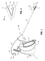
- Fig. 1 is a front, perspective view of an endoscopic surgical forceps configured for use in accordance with the present disclosure
- Fig. 2 is a front, perspective view of an open surgical forceps configured for use in accordance with the present disclosure
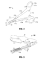
- Fig. 3 is a front, perspective view of the distal end of a surgical forceps including reposable jaw members configured for use in accordance with the present disclosure
- Fig. 4 is a front, perspective view of a surgical tissue clip configured for use in accordance with the present disclosure
- Fig. 5A is a transverse, cross-sectional view of an end effector assembly configured for use with any of the instruments of Figs. 1-4 ;
- Fig. 5B is a transverse, cross-sectional view of another end effector assembly configured for use with any of the instruments of Figs. 1-4 ;
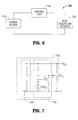
- Fig. 6 is a schematic illustration of power, heating, and control electronics configured for use with any of the end effector assemblies of Figs. 5A-5B ;
- Fig. 7 is a schematic diagram of a heating circuit configured for use with any of the end effector assemblies of Figs. 5A-5B ;
- Fig. 8 is a schematic diagram of a control circuit configured for use with any of the end effector assemblies of Figs. 5A-5B .
- Tissue heating can be accomplished by Joule heating, e.g., passing current through tissue; conductive heating, e.g., placing a heated surface in contact with or in close proximity to tissue; dielectric heating, e.g., applying a changing electric field to tissue; and/or frictional heating, e.g., creating friction within tissue.
- Joule heating e.g., passing current through tissue
- conductive heating e.g., placing a heated surface in contact with or in close proximity to tissue
- dielectric heating e.g., applying a changing electric field to tissue
- frictional heating e.g., creating friction within tissue.
- some of the challenges include achieving high power densities, a low thermal mass, a manufacturable package, temperature-sensing that is thermally linked with the heating elements, and temperature control.
- the present disclosure provides for the use of solid state devices, e.g., transistors and other heat generating components of solid state devices, as a source of heat for conductively heating tissue to thermally treat tissue.
- solid state heating systems can be incorporated into any suitable medical device configured to treat tissue.
- a solid state heating system of the present disclosure may be incorporated into: one or both jaw members of a surgical forceps configured to grasp tissue between its jaw members and heat tissue to seal tissue; an ablation probe used to internally heat tumors or other tissue to destroy the tumors or other tissue; or on a surface of a medical device configured to be placed over, around, or about tissue for warming the tissue to provide relief and/or promote healing. Accordingly, since the present disclosure is not limited to a particular instrument and/or configuration, the present disclosure will be described initially in a more general respect, followed by a more specific description of exemplary configurations.
- the solid state heating systems of the present disclosure may incorporate one or more solid state devices which include, for example, transistors, microprocessors, RAM, semiconductor diodes, integrated circuits (IC's), etc. Each of these components may themselves include any suitable type of transistor(s) (e.g., bipolar junction, field-effect, etc.), and/or other solid state heating components (e.g., resistive elements).
- the transistors may be configured to operate in various modes (e.g., switching or active) to generate heat for treating tissue. More specifically, heat generation by the transistors may be controlled by changing the operating point of one or more of the transistors (where the transistors are operating in an active mode), or by changing the switching frequency of one or more of the transistors (where the transistors are operating in a switching mode).
- This and other control functionality may be provided via analog circuitry, digital logic circuitry, and/or software operating on a microcontroller, the same or another solid state device, or a separate control device or system.
- Transistors based on different materials e.g., Si, GaAs, SiC, etc.
- Resistive elements within the solid state devices may also be specifically provided for generating heat via resistive loss, and may likewise be made from different materials (e.g., Si or other suitable metallic materials) depending on a particular purpose.
- the solid state devices may be operated at relatively high voltages to allow power to be transmitted at relatively smaller currents and to reduce transmission losses.
- the solid state heating systems of the present disclosure may include control circuitry, one or more temperature sensitive elements coupled to the control circuitry, and transistors (coupled to or integrated with the control circuitry) that are utilized to generate heat for heating tissue.
- the control circuitry can control the transistors, thereby controlling heat generation to achieve any desired trace of temperature versus time at the location of the temperature sensor.
- solid state devices can be very small, it is possible to achieve tight thermal coupling of the transistors, the temperature monitoring element, and the target tissue to thereby enable rapid and accurate thermal dosing of the target tissue.
- monitoring of the temperature sensitive element effectively becomes monitoring of the temperature of the target tissue and of the transistors.
- the solid state heating systems of the present disclosure may be formed from one or more solid state devices packaged individually and/or packaged together in one or more sets. Multiple packages of a system may be provided together on a substrate, may be coupled to one another, or may be remote from one another. In some embodiments, the package(s) themselves function as a tissue-contacting surface to facilitate the heating and thermal treatment of tissue using the heat generated by the transistors (or other components) of the solid state devices.
- the packages may further include control circuitry and/or sensor circuitry integrated therewith.
- the package(s) may be configured to define any suitable configuration, e.g., linear, curved, etc., depending on a particular purpose.
- Trapezoidal-shaped packages for example, allow adjacent packages to be fit together in either a linear or curved configuration (depending on their orientation), with minimal spacing between adjacent packages, to define a suitable tissue-contacting surface.
- the packages may further include specific features to facilitate tissue treatment, e.g., textured surfaces or projections to facilitate grasping tissue, stop features to inhibit contact between surfaces and/or define a gap distance therebetween, etc, and may additionally or alternatively be etched, cut, grinded, coated with a textured material, film, etc. to provide a particular surface feature such as, for example, anti-stick characteristics.
- the solid state heating systems of the present disclosure may be coupled to a separate control system, e.g., a control system that is not integrated into the heat-generating system.
- the solid state heating system may include one or more solid state devices configured for heat-generation and one or more solid state devices configured for control.
- the one or more heating generating devices and one or more control devices may comprise the same solid state device, may be separate solid state devices integrated into a single package, or may be separate packages (or standalone devices) of the system.
- Power may be provided to the solid state heating system, for example, via a battery (either integrated into the system or separate therefrom), or other power supply.
- Transistors of the solid state heating systems of the present disclosure may be provided in one or more groups and/or solid state devices, with multiple temperature sensors and/or other control components, to provide greater controllability of the system for achieving more uniform thermal treatment across tissue or providing different thermal treatments to different portions of tissue.
- Thermally conducting elements integrated into the solid state devices and/or thermally coupled to one or more of the solid state devices of a solid state heating system may also be provided to distribute heat generated by the heating components to likewise achieve more uniform thermal treatment across tissue or provide different thermal treatments to different portions of tissue.
- the solid state heating systems of the present disclosure may integrate or utilize one or more sensing elements such as temperature, pressure, proximity, optical absorption, reflectance, transmittance, Raman, or other types of sensors that measure characteristics of tissue and/or the system. These sensing elements may be integrated into the solid state devices or may be separate therefrom. For example, with respect to a surgical forceps, the solid state devices may be disposed within one of the jaw members, while one or more temperature sensors are disposed within on or the other jaw member to provide for better control of tissue heating by providing information on the rate at which heat is penetrating through tissue. Alternatively, solid state devices may be provided on both jaw members, with either or both including sensing elements.
- sensing elements such as temperature, pressure, proximity, optical absorption, reflectance, transmittance, Raman, or other types of sensors that measure characteristics of tissue and/or the system.
- the solid state devices or solid state heating systems of the present disclosure may be utilized, in addition to generating heat for thermally treating tissue, to provide control and/or power supply functionality.
- the solid state devices or solid state heating systems may be utilized to minimize thermal gradients between tissue heating components and the rest of the medical device, e.g., via mounting the solid state devices or solid state heating systems on the opposite side(s) of the device relative to the tissue-contacting surface(s) thereof, thus allowing for maximum power delivery to tissue with decreased thermal load on the device.
- the solid state heating systems of the present disclosure may utilize or incorporate heat-conducting elements to thermally connect the heat-generating transistors to tissue-contacting surface(s) of a device.
- active or passive elements may be thermally connected to the heat-generating components or the tissue-contacting surface(s) of a device to provide cooling.
- Such elements may include heat sinks that are cooled (rapidly or slowly) by: being thermally coupled to the heating system, ambient air, cooling water, thermo-electric cooling elements, etc.
- the heating systems of the present disclosure may be configured to provide suitable clearance within a device or portion thereof for other mechanical, electrical, or electro-mechanical components, mechanisms and/or systems. This may be accomplished by distributing one or more components of the heating system about the device, e.g., in one or more solid state devices or packages thereof, and/or distributing multiple solid state systems about the device.
- the distributed solid state devices and/or heating systems may be coupled to one another or may be independent of one another.
- Fig. 1 depicts an endoscopic surgical forceps 100 for use in connection with endoscopic surgical procedures
- Fig. 2 depicts an open surgical forceps 200 contemplated for use in connection with traditional open surgical procedures
- Fig. 3 depicts a reposable forceps 300
- Fig. 4 depicts a tissue clip 400.
- endoscopic forceps 100, open forceps 200, reposable forceps 300, tissue clip 400, or any other suitable medical device may be utilized in accordance with the present disclosure.
- different electrical and mechanical connections and considerations apply to each particular type of device; however, the novel aspects of the present disclosure and the operating characteristics thereof remain generally consistent regardless of the configuration of the device used therewith.
- endoscopic forceps 100 defines a longitudinal axis "A-A" and includes a housing 120, a handle assembly 130, a rotating assembly 170, a trigger assembly 180 and an end effector assembly 10.
- Forceps 100 further includes a shaft 112 having a distal end 114 configured to mechanically engage end effector assembly 10 and a proximal end 116 that mechanically engages housing 120.
- End effector assembly incorporates power, heat-generating, and control electronics therein for conductively heating tissue and controlling the heating of tissue to thermally treat tissue, thus obviating the need for supplying power, energy, and/or control signals to/from end effector assembly 10.
- forceps 100 may also include one or more wires (not shown) extending through shaft 112 to connect end effector assembly 10 to activation button 190 of housing 120 for activating/deactivating the power, heat-generating, and/or control electronics.
- end effector assembly 10 may be coupled to control circuitry, an external display, and/or a remote power source, e.g., an external power source, or a power source contained in another part of forceps 100, for example, handle assembly 130.
- handle assembly 130 includes a fixed handle 150 and a movable handle 140.
- Fixed handle 150 is integrally associated with housing 120 and handle 140 is movable relative to fixed handle 150.
- Rotating assembly 170 is rotatable in either direction about a longitudinal axis "A-A" to rotate end effector 10 about longitudinal axis "A-A.”
- Housing 120 houses the internal working components of forceps 100.
- End effector assembly 10 is shown attached at distal end 114 of shaft 112 and includes a pair of opposing jaw members 11 and 12.
- One or both of the jaw members 11 and 12 includes a thermally-conductive tissue-contacting surface 13, 14, respectively, configured to conduct thermal energy to tissue grasped between jaw members 11, 12 to thermally treat, e.g., seal, tissue.
- End effector assembly 10 is designed as a unilateral assembly, i.e., where jaw member 12 is fixed relative to shaft 112 and jaw member 11 is movable relative to shaft 112 and fixed jaw member 12.
- end effector assembly 10 may alternatively be configured as a bilateral assembly, i.e., where both jaw member 11 and jaw member 12 are movable relative to one another and to shaft 112.
- a knife assembly (not shown) is disposed within shaft 112 and a knife channel 615, 625 ( Fig. 5B ) is defined within one or both jaw members 11, 12 to permit reciprocation of a knife blade (not shown) therethrough, e.g., upon activation of trigger 182 of trigger assembly 180.
- end effector assembly 10 will be described in greater detail hereinbelow.
- movable handle 140 of handle assembly 130 is ultimately connected to a drive assembly (not shown) that, together, mechanically cooperate to impart movement of jaw members 11 and 12 between a spaced-apart position and an approximated position to grasp tissue between tissue-contacting surfaces 13 and 14 of jaw members 11, 12, respectively.
- a drive assembly (not shown) that, together, mechanically cooperate to impart movement of jaw members 11 and 12 between a spaced-apart position and an approximated position to grasp tissue between tissue-contacting surfaces 13 and 14 of jaw members 11, 12, respectively.
- movable handle 140 is initially spaced-apart from fixed handle 150 and, correspondingly, jaw members 11, 12 are disposed in the spaced-apart position.
- Movable handle 140 is depressible from this initial position to a depressed position corresponding to the approximated position of jaw members 11, 12.
- open forceps 200 is shown including two elongated shafts 212a and 212b, each having a proximal end 216a and 216b, and a distal end 214a and 214b, respectively.
- Forceps 200 is configured for use with an end effector assembly 20 that is similar to end effector assembly 10 of forceps 100 (see Fig. 1 ). More specifically, end effector assembly 20 is attached to distal ends 214a and 214b of shafts 212a and 212b, respectively, and includes a pair of opposing jaw members 21 and 22 that are movable relative to one another.
- Each shaft 212a and 212b includes a handle 217a and 217b disposed at the proximal end 216a and 216b thereof.
- Each handle 217a and 217b defines a finger hole 218a and 218b therethrough for receiving a finger of the user.
- finger holes 218a and 218b facilitate movement of shafts 212a and 212b relative to one another from an open position, wherein jaw members 21 and 22 are disposed in spaced-apart relation relative to one another, to a closed position, wherein jaw members 21 and 22 cooperate to grasp tissue therebetween.
- a ratchet 230 may be included for selectively locking jaw members 21 and 22 of forceps 200 relative to one another at various different positions.
- Ratchet 230 may include graduations or other visual markings that enable the user to easily and quickly ascertain and control the amount of closure force desired between the jaw members 21 and 22.
- end effector assembly 20 incorporates power, heat-generating, and control electronics therein for conductively heating tissue grasped between jaw members 21, 22 to thermally treat, e.g., seal, tissue, thus obviating the need for supplying power, energy, and/or control signals to/from end effector assembly 20, although end effector assembly 20 of forceps 200 may additionally or alternatively be coupled to a remote power source (not shown), control circuitry (not shown), and/or an external display (not shown).
- One or both of the jaw members 21 and 22 further includes a thermally-conductive tissue-contacting surface 23, 24, respectively, configured to facilitate the conduction of thermal energy to tissue grasped between jaw members 21, 22 to treat, e.g., seal, tissue.
- forceps 200 may further include a knife assembly (not shown) disposed within either of shafts 212a, 212b and a knife channel 615, 625 ( Fig. 5B ) defined within one or both jaw members 21, 22 to permit reciprocation of a knife blade (not shown) therethrough.
- a knife assembly (not shown) disposed within either of shafts 212a, 212b and a knife channel 615, 625 ( Fig. 5B ) defined within one or both jaw members 21, 22 to permit reciprocation of a knife blade (not shown) therethrough.
- reposable forceps 300 may be configured as an open forceps, e.g., similar to forceps 200 ( Fig. 2 ), an endoscopic forceps, e.g., similar to forceps 100 ( Fig. 1 ), or in any other suitable configuration.
- Reposable forceps 300 includes an end effector assembly 30 similar to end effector assemblies 10, 20 ( Figs. 1 , 2 , respectively), except that jaw members 31, 32 each include a fixed jaw frame 31 a, 32a and a removable jaw body 31 b, 32b, respectively.
- Jaw bodies 31 b, 32b are removably engagable with respective jaw frames 31 a, 32a and incorporate power, heat-generating, and control electronics therein for conductively heating tissue to thermally treat, e.g., seal, tissue.
- a pair of jaw bodies 31 b, 32b having a particular configuration e.g., including particularly configured power, heat-generating, and/or control electronics, may be selected and engaged to jaw frames 31 a, 31 b, respectively.
- This configuration not only provides for customization of forceps 300, but also obviates the need for supplying power, energy, and/or control signals to jaw bodies 31 b, 32b.
- jaw bodies 31 b, 32b allows the remainder of forceps 300 to include only mechanical components, thus reducing the complexity of forceps 300 and obviating the need for releasable electrical couplings between jaw bodies 31 b, 32b and respective jaw frames 31 a, 32a.
- Either or both of jaw bodies 31 b, 32b further includes a thermally-conductive tissue-treating surface 33, 34, respectively, adapted to conduct heat to tissue grasped between jaw members 31, 32 to thermally treat, e.g., seal, tissue.
- tissue clip 400 is an integrated or stand-alone end effector assembly including first and second jaw members 41, 42, respectively, coupled to one another by a flexible joint 43, although jaw members 41, 42 may alternatively be coupled to one another by a hinge, pivot, or any other suitable mechanism.
- Flexible joint 43 permits jaw members 41, 42 to move relative to one another between spaced-apart and approximated positions for grasping tissue therebetween.
- Jaw members 41, 42 of tissue clip 400 each further include a thermally-conductive tissue-contacting surface 44, 45, respectively.
- Power, heat-generating, and control electronics are disposed within either or both of jaw members 41, 42 for providing power to tissue clip 400, converting the power into thermal energy, and controlling the conduction of thermal energy to thermally-conductive tissue-contacting surfaces 44, 45 of jaw members 41, 42, respectively, to thermally treat, e.g., seal, tissue grasped between jaw members 41, 42.
- tissue clip 400 is a fully integrated tissue-treating unit incorporating all the necessary mechanical and electrical components therein for conductively heating tissue to thermally treat tissue.
- a latch mechanism 49 including first and second latch components 49a, 49b disposed on first and second jaw members 41, 42, respectively, may also be provided for selectively locking jaw members 41 and 42 relative to one another in various different positions.
- FIGs. 5A-5B various embodiments of end effector assemblies 500, 600, configured for use with forceps 100 ( Fig. 1 ), forceps 200 ( Fig. 2 ), forceps 300 ( Fig. 3 ), and/or tissue clip 400 ( Fig. 4 ) are shown. Although shown as separate embodiments, any or of all of the features of end effector assemblies 500, 600, to the extent that they are consistent, may similarly be used in conjunction with the other end effector assembly 500, 600. Further any of the features detailed above may be incorporated into end effector assemblies 500, 600 in addition to or as an alternative to the features detailed below.
- each end effector assembly 500, 600 incorporate heat-generating systems and control systems.
- End effector assembly 500 further incorporates a power system
- end effector assembly 600 is configured to couple to a remotely disposed power system, e.g., exteriorly of the surgical instrument or in another portion of the surgical instrument such as, for example, the handle assembly.
- the heat-generating systems of end effector assemblies 500, 600 are formed from one or more solid state devices incorporated into, forming, packaged to define, or otherwise disposed in thermal communication with the tissue-contacting surface(s) of one or both of the jaw members thereof to facilitate conductive heating of tissue grasped between the jaw members to thermally treat, e.g., seal, tissue.
- the control systems may likewise be incorporated into one or more solid state devices, packaged together or separate from the heat-generating systems.
- the need for external power, heat-generating, and/or control electronics is obviated.
- the use of a solid state heat-generating and/or control systems for conductive heating of tissue obviates the need to produce electrical energy, e.g., RF energy, microwave energy, etc., for transmission through tissue, thereby reducing the overall power requirements and complexity of the end effector assembly 500, 600.
- sufficiently small power sources e.g., batteries capable of being fully disposed within the end effector assembly 500, 600
- miniature solid state heat-generating elements e.g., transistor-based heating elements, and miniature solid state control elements, can be utilized.
- end effector assembly 500 includes first and second jaw members 510, 520, respectively, each including a jaw housing 511, 521 and a thermally-conductive tissue-contacting surface 512, 522, respectively.
- Jaw housings 511, 521 are formed from insulative materials and are supported on a respective jaw frame 513, 523.
- Jaw frames 513, 523 are coupled to one another, e.g., via a pivot (not shown), to permit movement of jaw members 510, 520 relative to one another between a spaced-apart position and an approximated position for grasping tissue therebetween.
- Tissue-contacting surfaces 512, 522 are disposed on jaw housings 511, 521, respectively, and are configured to grasp tissue therebetween upon movement of jaw members 510, 520 to the approximated position.
- Either or both of the tissue-contacting surfaces, e.g., tissue-contacting surface 512 is thermally coupled to one or more solid state heat-generating elements 530 such that heat produced by heat-generating elements 530 may be conducted to tissue-contacting surface 512 (and/or tissue-contacting surface 522) for conductively heating tissue grasped between jaw members 510, 520 to thermally treat, e.g., seal, tissue.
- a solid state, transistor-based heat-generating element 530 is described below (see Fig. 7 ), although other suitable solid state heat-generating elements 530 may also be provided as an alternative or in addition to transistor-based heating elements.
- One of the jaw members may include a power source, e.g., a battery 540, disposed therein that is coupled to heat generating elements 530 for providing power to end effector assembly 500, e.g., for powering heat-generating elements 530.
- a power source e.g., a battery 540
- one of the jaw members e.g., jaw member 510
- Control unit 550 may further be configured to control other components of the medical device associated with end effector assembly 500.
- one or both of the jaw members further includes a substrate 514 disposed therein and positioned adjacent to and in thermal communication with the tissue-contacting surface 512 thereof.
- Substrate 514 incorporates, contains, mounts, supports, or otherwise couples to solid-state heat-generating elements 530 and/or solid state control unit 550.
- Substrate 514 may be the substrate upon which heat generating elements 530 and/or control unit 550 is formed, e.g., a silicon wafer.
- substrate 514 may be formed at least partially from a printed circuit board (PCB), a ceramic substrate, FR4 substrate, rigid plastic or composite substrate, flexible substrate (e.g., a flex circuit including polyimide, PEEK, polyester, PET, etc.), or any other suitable substrate or assembly that incorporates, mounts, receives or couples to heat-generating elements 530 and/or control unit 550.
- PCB printed circuit board
- ceramic substrate e.g., FR4 substrate
- rigid plastic or composite substrate e.g., a flex circuit including polyimide, PEEK, polyester, PET, etc.
- flexible substrate e.g., a flex circuit including polyimide, PEEK, polyester, PET, etc.
- any other suitable substrate or assembly that incorporates, mounts, receives or couples to heat-generating elements 530 and/or control unit 550.
- Substrate 514 may further be configured to facilitate the conduction or transfer of heat from the heat-generating elements 530 to tissue-contacting surface 512, e.g., substrate 514 may be formed from a thermally-conductive material in contact with tissue-contacting surface 512 or may otherwise be configured to facilitate thermal conduction between heat-generating elements 530 and tissue-contacting surface 512 (e.g., via wires, traces, other conductive elements, etc.). Substrate 514 may also define or incorporate the tissue-contact surface 512 therein or thereon and, in such embodiments, may further be configured to include any of the features detailed above. Insulative jaw housing 511 encapsulates substrate 514 such that substrate 514 is thermally coupled to tissue-contacting surface 512, but is otherwise surrounded by a thermally insulating material.
- Battery 540 and/or control unit 550 may likewise be incorporated into, mounted, or otherwise coupled to substrate 514, similarly as detailed above with respect to heat-generating elements 530. More specifically, heat-generating elements 530, battery 540, and/or control unit 550 may be formed on substrate 514 as one or more solid state devices, e.g., integrated circuits (ICs) on a PCB, multi-chip modules (MCMs) packaged in a ceramic (or other suitable) substrate, System-in-Package (SiP) modules, a microprocessor, or other suitable electronics for generating heat to conductively heat tissue and control the heating of tissue.
- solid state devices e.g., integrated circuits (ICs) on a PCB, multi-chip modules (MCMs) packaged in a ceramic (or other suitable) substrate, System-in-Package (SiP) modules, a microprocessor, or other suitable electronics for generating heat to conductively heat tissue and control the heating of tissue.
- ICs integrated circuits
- Fig. 3 in addition to Fig. 5A , with regard to reposable forceps 300, rather than requiring an entirely new or different instrument customized for a particular procedure, all that is required is a new or different pair of jaw bodies 31 b, 32b having a desired configuration of power, heat-generating, and/or control electronics.
- various different jaw bodies 31 b, 32b may be provided for use with reposable forceps 300, each having a differently configured control unit and/or heat-generating element(s) to, for example, provide various different thermal treatment parameters and/or sealing algorithms.
- a generic reusable instrument configured to engage a desired set of jaw bodies 31 b, 32b may be customized in accordance with the particular procedure to be performed.
- Jaw bodies 31 b, 32b may also be configured for use with various different instruments, e.g., an endoscopic forceps similar to forceps 100 ( Fig.
- tissue clips 400 ( Fig. 4 ) or an open forceps similar to forceps 200 ( Fig. 2 ), depending on a particular purpose.
- tissue clips 400 various different tissue clips 400 ( Fig. 4 ), each having a control unit and heat-generating element configured, e.g., having particular thermal treatment parameters and/or sealing algorithms, in accordance with a particular procedure, type/size of tissue, etc., may be provided.
- Exemplary control circuitry for incorporation into the control unit 550 of the various jaw bodies 31 b, 32b and/or tissue clips 400 ( Fig. 4 ) are described below.
- coupling control unit 550, and/or heat-generating elements 530 together within one or more solid state devices on or in a substrate or package allows for a minimal number of required external connections.
- such an integrated solid state device or device(s) in a package may require only three external connections: power, ground (return), and a control line for manually activating the device or manually terminating operation (see Fig. 5B ).
- the control line may further be configured to enable calibration, programming, synchronizing, updating, selecting different operating modes, etc.
- control unit 550 is coupled to battery 540 and/or heat-generating elements 530, or may include or be integrated with battery 540 and/or heat-generating elements 530 in one or more solid state devices, via packaging, or a substrate.
- Control unit 550 may include solid state or other components including, for example, logic or processing circuitry, e.g., microprocessors, field-programmable gate arrays (FPGAs), discrete logic circuits, etc.; timing circuitry; and/or other control circuitry for controlling, e.g., turning on/off, heat-generating elements 530 in accordance with one or more parameters, algorithms, or cycles.
- logic or processing circuitry e.g., microprocessors, field-programmable gate arrays (FPGAs), discrete logic circuits, etc.
- timing circuitry e.g., timing circuitry
- other control circuitry for controlling, e.g., turning on/off, heat-generating elements 530 in accordance with one or more parameters, algorithms, or cycles.
- control unit 550 may include or be coupled to one or more sensing elements 560, e.g., temperature sensors, pressure sensors, tissue property sensors, etc.
- Sensing element 560 may be configured, for example, to sense the temperature and/or other properties of tissue grasped between jaw members 510, 520 such that control unit 550, in conjunction with sensing element 560, can control the thermal treatment of tissue via a feedback loop.
- Control unit 550 may include one or more solid state devices, e.g., ICs, incorporated into substrate 514 or a package, or may assume any other suitable configuration, such as those mentioned above.
- control circuitry of the control unit 550 and/or the type and configuration of sensing elements 560 used therewith may be selected in accordance with the particular procedure to be performed, the type/size of tissue to be treated, and/or other factors.
- various reposable jaw bodies 31 b, 32b ( Fig. 3 ) and/or various tissue clips 400 ( Fig. 4 ) may be provided, each incorporating a differently configured control unit 550 adapted for use in a particular procedure (or procedures).
- end effector assembly 500 in conjunction with forceps 100 is described. Although the use and operation of end effector assembly 500 is described with respect to forceps 100, end effector assembly 500 may be similarly configured for use with forceps 200, forceps 300, or tissue clip 400 ( Figs. 2, 3 , and 4 , respectively).
- end effector assembly 500 is maneuvered into position such that tissue to be grasped and thermally treated, e.g., sealed, is disposed between jaw members 510, 520.
- movable handle 140 is depressed, or pulled proximally relative to fixed handle 150 such that jaw member 510 is pivoted relative to jaw member 520 from the spaced-apart position to the approximated position to grasp tissue therebetween.
- a drive assembly (not shown) is activated such that a drive bar (not shown) is translated proximally through shaft 112, urging jaw member 510 to pivot relative to jaw member 520 from the spaced-apart position to the approximated position.
- control unit 550 is activated, e.g., manually via depression of activation switch 190 of forceps 100 or automatically upon approximation of jaw members 510, 520 (or upon occurrence of some other condition) as determined by control unit 550 and sensing elements 560, such that power is supplied from battery 540 to heat-generating elements 530.
- heat-generating elements 530 produce heat that is conducted to tissue grasped between jaw members 510, 520 via substrate 514 and tissue-contacting surfaces 512, 514 to conductively heat tissue.
- Control unit 550 may be configured to control the heating of tissue in conjunction with sensing elements 560 via feedback control, using a timing circuit, e.g., maintaining heat-generating elements 530 at a pre-determined temperature for a pre-determined time, or via any other suitable control mechanism to thermally treat tissue as desired.
- a timing circuit e.g., maintaining heat-generating elements 530 at a pre-determined temperature for a pre-determined time, or via any other suitable control mechanism to thermally treat tissue as desired.
- Control unit 550 of end effector assembly 500 may thus be configured to control the heating of tissue in accordance with one or more of these factors, such that formation of an effective tissue seal (or otherwise effectively treating tissue) can be achieved.
- control unit 550 and heat-generating elements 530 cooperate to start, regulate, and end the heating of tissue to facilitate formation of an effective tissue seal.
- control unit 550 may be configured to individually and/or collectively control heat-generating elements 530 to achieve a more uniform tissue seal or other desired tissue effect.
- the particular control settings and configuration of control unit 550 may be varied.
- control unit 550 may further include or may be coupled to one or more sensing elements 560 disposed on or along jaw member 510 (and/or jaw member 520) that are configured to automatically sense various properties of tissue or jaw members 510, 520 including, but not limited to: tissue type, tissue clarity, tissue compliance, tissue temperature, temperature of jaw members 510, 520, temperature of heat-generating elements 530, temperature of substrate 514, water content in tissue, opening angle of jaw members 510, 520, water motility in tissue, and/or jaw member closure pressure.
- Sensing elements 560 provide measurements to control unit 550, thus allowing control unit 550 to control heat-generating elements 530, e.g., to turn on/off one or more of heat generating elements 530, to heat tissue in accordance with the one or more properties of tissue and/or jaw members 510, 520 (and/or any of the components thereof) detected by sensing elements 560.
- a knife (not shown) may be advanced from shaft 112 of forceps 100 between jaw members 510, 520 to cut the previously-sealed tissue grasped therebetween, e.g., upon actuation of trigger 182 of trigger assembly 180.
- control unit 550 incorporates a thermal cutting algorithm or thermal cutting parameters
- heat generating-elements 530 may be configured to conduct thermal energy to tissue to thermally dissect tissue along the previously-formed tissue seal.
- jaw members 510, 520 may be returned to the spaced-apart position to release the sealed and/or divided tissue, e.g., via moving movable handle 140 back to the initial position.
- FIG. 5B another embodiment of an end effector assembly 600 configured for use with forceps 100 ( Fig. 1 ), forceps 200 ( Fig. 2 ), forceps 300 ( Fig. 3 ), and/or tissue clip 400 ( Fig. 4 ) is shown.
- End effector assembly 600 is similar to end effector assembly 500 ( Fig. 5A ) and may includes any of the features thereof, and vice versa. For purposes of brevity, only the differences between end effector assembly 600 and end effector assembly 500 ( Fig. 5A ) will be described in detail hereinbelow.
- End effector assembly 600 includes first and second jaw members 610, 620, respectively, each including a jaw housing 611, 621 supported on a jaw frame 613, 623 and a pair of tissue-contacting surfaces 612a, 612b and 622a, 622b disposed on respective jaw housings 611, 621.
- One or both of jaw members 610, 620 is movable relative to the other between a spaced-apart position and an approximated position for grasping tissue therebetween.
- each jaw member 610, 620 are disposed on either side of a respective knife channel 615, 625 extending longitudinally through the respective jaw member 610, 620, and are configured to conduct heat to tissue grasped between jaw members 610, 620 to thermally treat, e.g., seal, tissue.
- each jaw member 610, 620 includes a pair of packages 614a, 614b and 624a, 624b disposed on either side of knife channels 615, 625, respectively, that define the respective tissue-contacting surfaces 612a, 612b and 622a, 622b of jaw members 610, 620.
- packages 614a, 614b and 624a, 624b substrates defining tissue-contacting surfaces 612a, 612b and 622a, 622b may alternatively be provided.
- Each package 614a, 614b and 624a, 624b incorporates one or more solid state heat-generating elements 630 and one or more solid state control units 650 for controlling the respective heat-generating elements 630.
- Packages 614a, 614b and 624a, 624b are coupled to an external power source (not explicitly shown) via wires 641, 642 and 643, 644, respectively.
- Sensing elements may also be provided for use in conjunction with one or more of packages 614a, 614b, 624a, 624b.
- the heat-generating element(s) 630 corresponding to each package 614a, 614b and 624a, 624b may be independently or collectively operated to achieve a desired tissue effect.
- FIG. 6-8 schematics of an electronics system 700, e.g., the power source 710, the heat-generating element 720, and the control unit 750, configured for use with end effector assemblies 500, 600 ( Figs. 5A-5B , respectively), or any other suitable end effector assembly, are shown and described. As shown in Fig.
- the electronics system 700 of each end effector assembly generally incorporates a power source 710, e.g., a battery, one or more heat-generating elements 720, and a control unit 750 that are coupled to one another (in any suitable configuration, such as those detailed above) to conductively heat and control the heating of tissue to achieve a desired tissue effect, e.g., to seal tissue.
- a power source 710 e.g., a battery
- heat-generating elements 720 e.g., a heat-generating elements 720
- control unit 750 that are coupled to one another (in any suitable configuration, such as those detailed above) to conductively heat and control the heating of tissue to achieve a desired tissue effect, e.g., to seal tissue.
- Heat-generating circuit 730 for the heat-generating element 720 is shown configured as a constant-temperature heat source.
- Heat-generating circuit 730 is formed as a transistor-based, solid state heating device configured to receive power from power source 710 and to produce heat for conduction to tissue to thermally treat tissue.
- heat-generating circuit 730 includes a power supply V cc that is coupled to power source 710 for receiving power therefrom, a power-dissipating, e.g., heat-producing, Field-Effect Transistor (FET) FET 1 , e.g., a Metal-Oxide-Semiconductor Field-Effect transistor (MOSFET) or a junction gate field-effect transistor (JFET), a temperature-control circuit 732, and a biasing circuit 734.
- the biasing circuit 734 is configured to operate FET 1 in a highly dissipating manner to produce heat for conductively heating tissue.
- the temperature-control circuit 732 includes a positive temperature coefficient thermistor PTC 1 thermally coupled to FET 1 for substantially maintaining FET 1 at a constant temperature. That is, as FET 1 heats up, PTC 1 likewise heats up, thereby increasing in resistance and reducing the drive to FET 1 by switching ON the transistor Tr. When the FET 1 cools down, PTC 1 likewise cools down and its resistance decreases such that the drive to FET 1 is increased by switching OFF the transistor Tr. Thus, FET 1 can be heated to and maintained at a substantially constant temperature, or within a sufficiently narrow temperature range.
- control circuit 760 for the control unit 750 is shown configured for electrical coupling between the power source 710 and heat-generating element 720 for controlling, e.g., turning ON/OFF, the supply of electrical energy to heat-generating element 720.
- Control circuit 760 is configured as an analog timing circuit for heating tissue to a pre-determined temperature for a pre-determined amount of time, although other suitable control circuits are also contemplated utilizing either analog or digital methods. More specifically, control circuit 760 includes a sensing element 762 (similar to sensing element 560 ( Fig.
- a PTC thermistor PTC 2 configured to sense the temperature of tissue to be thermally treated
- a FET FET 2 that is coupled between power source 710 and heat-generating element 720 for turning ON/OFF the supply of power to heat-generating element 720 such that tissue in thermal contact with temperature-sensing element 762 can be heated to a target temperature and maintained at or above that target temperature for a pre-determined amount of time to facilitate thermal tissue treatment, e.g., tissue sealing.
- control circuit 760 may be used with a constant-temperature heat-generating element 720, although control circuit 760 may also be used with other suitable heat-generating elements 720.
- temperature-sensing element 762 may be positioned on or in the jaw member opposing the jaw member containing heat-generating element 720. In this configuration, upon activation of heat-generating element 720, tissue contacting the jaw member containing heat-generating element 720 is heated relatively quickly to and is maintained at the predetermined "constant" temperature.
- Heat-generating element 720 is maintained at this predetermined "constant" temperature until temperature-sensing element 762, which is disposed on or in the opposing jaw member, has been sufficiently heated, indicating that tissue adjacent temperature-sensing element 762 has been sufficiently heated.
- control circuit 760 operates to turn OFF the supply of power to heat-generating element 720.
- momentary contact switch S is used to zero the voltage across capacitor C, turning on FET 2 , and initiating heating by heat-generating element 720.
- Capacitor C charges very slowly through resistor R 2 , which defines an upper bound on the duration of the heating cycle.
- temperature-sensing element 762 As temperature-sensing element 762 is heated, its resistance increases, raising the voltage of the node between it and resistor R 1 and eventually allowing capacitor C to be charged through diode D with a time constant determined by the capacitance and the resistance of the voltage divider formed by R 1 and temperature-sensing element 762. This rate is typically much faster than the charging of capacitor C via R 2 .
- the increasing voltage across capacitor C eventually turns off FET 2 , ending the heating cycle.
- timing circuit 760 is activated (and the charging of capacitor C begins) once tissue to be thermally treated reaches the target temperature, as sensed by sensing element 762. Capacitor C is charged to equilibrium (over a pre-determined amount of time), at which point FET 2 is switched OFF to cut off the supply of power to heat-generating element 720. That is, timing circuit 760 turns OFF heat-generating element 720 once tissue has been heated to the target temperature for a pre-determined amount of time.
- Thermistor PTC 2 , resistors R 1, R 2 , and capacitor C may be configured in accordance with a desired target temperature and "on time" of the control circuit 760.
- the target temperature and "on time” may depend on the particular procedure to be performed, the type/size of tissue to be thermally treated and/or other factors.
- various different jaw bodies 31 b, 32b of a reposable forceps 300 see Fig. 3
- various different tissue clips 400 Fig. 4
- each configured for a particular procedure (or procedures) e.g., each incorporating a control circuit 760 having a target temperature and "on time" adapted for a particular procedure (or procedures).
- Momentary contact switch S which, as mentioned above, is used to zero the voltage across capacitor C, turn on FET 2 , and initiate heating by heat-generating element 720, may be coupled to activation switch 190 ( Fig. 1 ) of forceps 100 for manually controlling the initiation of the heating cycle upon activation of activation switch 190, while completion of the heating cycle, e.g., once tissue has been heated to the target temperature for the pre-determined amount of time, is automatically controlled via control circuit 760.
Landscapes
- Health & Medical Sciences (AREA)
- Surgery (AREA)
- Engineering & Computer Science (AREA)
- Life Sciences & Earth Sciences (AREA)
- Biomedical Technology (AREA)
- Molecular Biology (AREA)
- Nuclear Medicine, Radiotherapy & Molecular Imaging (AREA)
- Plasma & Fusion (AREA)
- Physics & Mathematics (AREA)
- Heart & Thoracic Surgery (AREA)
- Medical Informatics (AREA)
- Otolaryngology (AREA)
- Animal Behavior & Ethology (AREA)
- General Health & Medical Sciences (AREA)
- Public Health (AREA)
- Veterinary Medicine (AREA)
- Surgical Instruments (AREA)
- Thermotherapy And Cooling Therapy Devices (AREA)
Applications Claiming Priority (3)
| Application Number | Priority Date | Filing Date | Title |
|---|---|---|---|
| US201261708840P | 2012-10-02 | 2012-10-02 | |
| US201361809061P | 2013-04-05 | 2013-04-05 | |
| US14/029,893 US9439711B2 (en) | 2012-10-02 | 2013-09-18 | Medical devices for thermally treating tissue |
Publications (2)
| Publication Number | Publication Date |
|---|---|
| EP2716250A2 true EP2716250A2 (fr) | 2014-04-09 |
| EP2716250A3 EP2716250A3 (fr) | 2017-05-03 |
Family
ID=49322210
Family Applications (1)
| Application Number | Title | Priority Date | Filing Date |
|---|---|---|---|
| EP13187073.5A Withdrawn EP2716250A3 (fr) | 2012-10-02 | 2013-10-02 | Dispositifs médicaux pour le traitement thermique de tissus |
Country Status (4)
| Country | Link |
|---|---|
| US (2) | US9439711B2 (fr) |
| EP (1) | EP2716250A3 (fr) |
| AU (1) | AU2013237661A1 (fr) |
| CA (1) | CA2828245C (fr) |
Cited By (2)
| Publication number | Priority date | Publication date | Assignee | Title |
|---|---|---|---|---|
| US11344707B2 (en) | 2016-11-28 | 2022-05-31 | Therma Bright Inc. | Devices for applying a topical treatment |
| US11992640B2 (en) | 2016-11-28 | 2024-05-28 | The Jenex Corporation | Devices for applying a topical treatment |
Families Citing this family (3)
| Publication number | Priority date | Publication date | Assignee | Title |
|---|---|---|---|---|
| WO2015167623A2 (fr) * | 2014-04-29 | 2015-11-05 | William Dean Wallace | Procédés de traitement et dispositifs chirurgicaux portatifs pour le traitement de cellules hyperplasiques et néoplasiques dans le col de l'utérus et autres troubles dermatologiques ou superficiels |
| CN109922749B (zh) * | 2016-11-09 | 2021-10-12 | 奥林巴斯株式会社 | 医疗设备 |
| WO2018150533A1 (fr) * | 2017-02-17 | 2018-08-23 | オリンパス株式会社 | Outil de traitement |
Family Cites Families (215)
| Publication number | Priority date | Publication date | Assignee | Title |
|---|---|---|---|---|
| SU401367A1 (ru) | 1971-10-05 | 1973-10-12 | Тернопольский государственный медицинский институт | Биактивный электрохирургическнп инструмент |
| DE2415263A1 (de) | 1974-03-29 | 1975-10-02 | Aesculap Werke Ag | Chirurgische hf-koagulationssonde |
| DE2514501A1 (de) | 1975-04-03 | 1976-10-21 | Karl Storz | Bipolares coagulationsinstrument fuer endoskope |
| FR2315286A2 (fr) | 1975-06-26 | 1977-01-21 | Lamidey Marcel | Pince a dissequer, hemostatique, haute frequence |
| USD249549S (en) | 1976-10-22 | 1978-09-19 | Aspen Laboratories, Inc. | Electrosurgical handle |
| US4219025A (en) * | 1978-11-16 | 1980-08-26 | Corning Glass Works | Electrically heated surgical cutting instrument |
| USD263020S (en) | 1980-01-22 | 1982-02-16 | Rau Iii David M | Retractable knife |
| DE3490633T (de) | 1984-01-30 | 1985-12-12 | Char'kovskaja oblastnaja kliničeskaja bol'nica, Char'kov | Bipolares elektrochirurgisches Gerät |
| JPS60211451A (ja) | 1984-04-05 | 1985-10-23 | Asahi Chem Ind Co Ltd | 感光性エラストマ−組成物 |
| DE3423356C2 (de) | 1984-06-25 | 1986-06-26 | Berchtold Medizin-Elektronik GmbH & Co, 7200 Tuttlingen | Elektrochirurgisches Hochfrequenz-Schneidinstrument |
| US4657016A (en) | 1984-08-20 | 1987-04-14 | Garito Jon C | Electrosurgical handpiece for blades, needles and forceps |
| USD299413S (en) | 1985-07-17 | 1989-01-17 | The Stanley Works | Folding pocket saw handle |
| USD295893S (en) | 1985-09-25 | 1988-05-24 | Acme United Corporation | Disposable surgical clamp |
| USD295894S (en) | 1985-09-26 | 1988-05-24 | Acme United Corporation | Disposable surgical scissors |
| USD298353S (en) | 1986-05-06 | 1988-11-01 | Vitalmetrics, Inc. | Handle for surgical instrument |
| JPH0540112Y2 (fr) | 1987-03-03 | 1993-10-12 | ||
| DE8712328U1 (de) | 1987-09-11 | 1988-02-18 | Jakoubek, Franz, 7201 Emmingen-Liptingen | Endoskopiezange |
| JP2806511B2 (ja) | 1990-07-31 | 1998-09-30 | 松下電工株式会社 | 合金系焼結体の製法 |
| US5389102A (en) | 1990-09-13 | 1995-02-14 | United States Surgical Corporation | Apparatus and method for subcuticular stapling of body tissue |
| US5190541A (en) | 1990-10-17 | 1993-03-02 | Boston Scientific Corporation | Surgical instrument and method |
| JP2951418B2 (ja) | 1991-02-08 | 1999-09-20 | トキコ株式会社 | 試料液成分分析装置 |
| US5330471A (en) | 1991-06-07 | 1994-07-19 | Hemostatic Surgery Corporation | Bi-polar electrosurgical endoscopic instruments and methods of use |
| USD348930S (en) | 1991-10-11 | 1994-07-19 | Ethicon, Inc. | Endoscopic stapler |
| JPH0630945A (ja) | 1992-05-19 | 1994-02-08 | Olympus Optical Co Ltd | 縫合器 |
| USD349341S (en) | 1992-10-28 | 1994-08-02 | Microsurge, Inc. | Endoscopic grasper |
| DE4303882C2 (de) | 1993-02-10 | 1995-02-09 | Kernforschungsz Karlsruhe | Kombinationsinstrument zum Trennen und Koagulieren für die minimal invasive Chirurgie |
| JP3390041B2 (ja) | 1993-04-05 | 2003-03-24 | オリンパス光学工業株式会社 | 鉗 子 |
| GB9309142D0 (en) | 1993-05-04 | 1993-06-16 | Gyrus Medical Ltd | Laparoscopic instrument |
| USD343453S (en) | 1993-05-05 | 1994-01-18 | Laparomed Corporation | Handle for laparoscopic surgical instrument |
| USD354564S (en) | 1993-06-25 | 1995-01-17 | Richard-Allan Medical Industries, Inc. | Surgical clip applier |
| US5693051A (en) | 1993-07-22 | 1997-12-02 | Ethicon Endo-Surgery, Inc. | Electrosurgical hemostatic device with adaptive electrodes |
| US5688270A (en) | 1993-07-22 | 1997-11-18 | Ethicon Endo-Surgery,Inc. | Electrosurgical hemostatic device with recessed and/or offset electrodes |
| GB9322464D0 (en) | 1993-11-01 | 1993-12-22 | Gyrus Medical Ltd | Electrosurgical apparatus |
| USD358887S (en) | 1993-12-02 | 1995-05-30 | Cobot Medical Corporation | Combined cutting and coagulating forceps |
| DE4403252A1 (de) | 1994-02-03 | 1995-08-10 | Michael Hauser | Instrumentenschaft für die minimalinvasive Chirurgie |
| GB9413070D0 (en) | 1994-06-29 | 1994-08-17 | Gyrus Medical Ltd | Electrosurgical apparatus |
| USD384413S (en) | 1994-10-07 | 1997-09-30 | United States Surgical Corporation | Endoscopic suturing instrument |
| GB9425781D0 (en) | 1994-12-21 | 1995-02-22 | Gyrus Medical Ltd | Electrosurgical instrument |
| DE19506363A1 (de) | 1995-02-24 | 1996-08-29 | Frost Lore Geb Haupt | Verfahren zur nicht-invasiven Thermometrie in Organen unter medizinischen Hyperthermie- und Koagulationsbedingungen |
| JPH08289895A (ja) | 1995-04-21 | 1996-11-05 | Olympus Optical Co Ltd | 縫合器 |
| DE19515914C1 (de) | 1995-05-02 | 1996-07-25 | Aesculap Ag | Zangen- oder scherenförmiges chirurgisches Instrument |
| JPH09538A (ja) | 1995-06-21 | 1997-01-07 | Fuji Photo Optical Co Ltd | 高周波処置具 |
| US6293942B1 (en) | 1995-06-23 | 2001-09-25 | Gyrus Medical Limited | Electrosurgical generator method |
| JPH1024051A (ja) | 1995-09-20 | 1998-01-27 | Olympus Optical Co Ltd | 切離機能付凝固鉗子 |
| USH1745H (en) | 1995-09-29 | 1998-08-04 | Paraschac; Joseph F. | Electrosurgical clamping device with insulation limited bipolar electrode |
| AU703455B2 (en) | 1995-10-20 | 1999-03-25 | Ethicon Endo-Surgery, Inc. | Self protecting knife for curved jaw surgical instruments |
| US5980518A (en) * | 1995-10-27 | 1999-11-09 | Carr; William N. | Microcautery surgical tool |
| US5673842A (en) | 1996-03-05 | 1997-10-07 | Ethicon Endo-Surgery | Surgical stapler with locking mechanism |
| DE19608716C1 (de) | 1996-03-06 | 1997-04-17 | Aesculap Ag | Bipolares chirurgisches Faßinstrument |
| USD408018S (en) | 1996-03-12 | 1999-04-13 | Mcnaughton Patrick J | Switch guard |
| CA2221414C (fr) | 1996-03-18 | 2006-05-02 | 688726 Alberta Ltd. | Dispositif d'electrotherapie |
| USD416089S (en) | 1996-04-08 | 1999-11-02 | Richard-Allan Medical Industries, Inc. | Endoscopic linear stapling and dividing surgical instrument |
| DE29616210U1 (de) | 1996-09-18 | 1996-11-14 | Olympus Winter & Ibe Gmbh, 22045 Hamburg | Handhabe für chirurgische Instrumente |
| US5923475A (en) | 1996-11-27 | 1999-07-13 | Eastman Kodak Company | Laser printer using a fly's eye integrator |
| JP3836551B2 (ja) | 1996-12-04 | 2006-10-25 | ペンタックス株式会社 | 内視鏡用ホットバイオプシー鉗子 |
| US5891142A (en) | 1996-12-06 | 1999-04-06 | Eggers & Associates, Inc. | Electrosurgical forceps |
| US6626901B1 (en) | 1997-03-05 | 2003-09-30 | The Trustees Of Columbia University In The City Of New York | Electrothermal instrument for sealing and joining or cutting tissue |
| USH1904H (en) | 1997-05-14 | 2000-10-03 | Ethicon Endo-Surgery, Inc. | Electrosurgical hemostatic method and device |
| USH2037H1 (en) | 1997-05-14 | 2002-07-02 | David C. Yates | Electrosurgical hemostatic device including an anvil |
| JP3986126B2 (ja) | 1997-08-04 | 2007-10-03 | オリンパス株式会社 | 内視鏡下手術器械 |
| JP3986127B2 (ja) | 1997-08-06 | 2007-10-03 | オリンパス株式会社 | 内視鏡下手術器械 |
| US6083223A (en) * | 1997-08-28 | 2000-07-04 | Baker; James A. | Methods and apparatus for welding blood vessels |
| DE19738457B4 (de) | 1997-09-03 | 2009-01-02 | Celon Ag Medical Instruments | Verfahren und Vorrichtung für die In-vivo-Tiefenkoagulation biologischer Gewebevolumina bei gleichzeitiger Schonung der Gewebeoberfläche mit hochfrequentem Wechselstrom |
| US5980510A (en) | 1997-10-10 | 1999-11-09 | Ethicon Endo-Surgery, Inc. | Ultrasonic clamp coagulator apparatus having improved clamp arm pivot mount |
| USD402028S (en) | 1997-10-10 | 1998-12-01 | Invasatec, Inc. | Hand controller for medical system |
| DE19751108A1 (de) | 1997-11-18 | 1999-05-20 | Beger Frank Michael Dipl Desig | Elektrochirurgisches Operationswerkzeug |
| JPH11169381A (ja) | 1997-12-15 | 1999-06-29 | Olympus Optical Co Ltd | 高周波処置具 |
| EP0923907A1 (fr) | 1997-12-19 | 1999-06-23 | Gyrus Medical Limited | Instrument électrochirurgical. |
| US6322584B2 (en) * | 1998-07-31 | 2001-11-27 | Surx, Inc. | Temperature sensing devices and methods to shrink tissues |
| JP4225624B2 (ja) | 1998-08-27 | 2009-02-18 | オリンパス株式会社 | 高周波処置装置 |
| USD425201S (en) | 1998-10-23 | 2000-05-16 | Sherwood Services Ag | Disposable electrode assembly |
| USD449886S1 (en) | 1998-10-23 | 2001-10-30 | Sherwood Services Ag | Forceps with disposable electrode |
| CA2347014C (fr) | 1998-10-23 | 2011-01-04 | Sherwood Services Ag | Pince de suture de vaisseaux ouverts dotee d'electrodes |
| USD424694S (en) | 1998-10-23 | 2000-05-09 | Sherwood Services Ag | Forceps |
| DE19858512C1 (de) | 1998-12-18 | 2000-05-25 | Storz Karl Gmbh & Co Kg | Bipolares medizinisches Instrument |
| US6235027B1 (en) * | 1999-01-21 | 2001-05-22 | Garrett D. Herzon | Thermal cautery surgical forceps |
| US20030171747A1 (en) | 1999-01-25 | 2003-09-11 | Olympus Optical Co., Ltd. | Medical treatment instrument |
| DE19915061A1 (de) | 1999-04-01 | 2000-10-26 | Erbe Elektromedizin | Chirurgisches Instrument |
| GB9911954D0 (en) | 1999-05-21 | 1999-07-21 | Gyrus Medical Ltd | Electrosurgery system and instrument |
| GB9911956D0 (en) | 1999-05-21 | 1999-07-21 | Gyrus Medical Ltd | Electrosurgery system and method |
| GB9912627D0 (en) | 1999-05-28 | 1999-07-28 | Gyrus Medical Ltd | An electrosurgical instrument |
| GB9912625D0 (en) | 1999-05-28 | 1999-07-28 | Gyrus Medical Ltd | An electrosurgical generator and system |
| GB9913652D0 (en) | 1999-06-11 | 1999-08-11 | Gyrus Medical Ltd | An electrosurgical generator |
| JP2001003400A (ja) | 1999-06-21 | 2001-01-09 | Sumitomo Constr Mach Co Ltd | 油圧ショベルのモニター装置 |
| JP2001029355A (ja) | 1999-07-21 | 2001-02-06 | Olympus Optical Co Ltd | 電気メス装置 |
| DE19940689A1 (de) | 1999-08-27 | 2001-04-05 | Storz Karl Gmbh & Co Kg | Bipolares medizinisches Instrument |
| USD465281S1 (en) | 1999-09-21 | 2002-11-05 | Karl Storz Gmbh & Co. Kg | Endoscopic medical instrument |
| DE19946527C1 (de) | 1999-09-28 | 2001-07-12 | Storz Karl Gmbh & Co Kg | Medizinisches bipolares Instrument zum Fassen, Koagulieren und Schneiden von Gewebe |
| DE19954424A1 (de) * | 1999-11-11 | 2001-06-07 | Hansgeorg Schuldzig | Einrichtung zur lokalen thermischen Behandlung von Insektenstichen und -bissen |
| JP4315557B2 (ja) | 2000-01-12 | 2009-08-19 | オリンパス株式会社 | 医療用処置具 |
| DE10003020C2 (de) | 2000-01-25 | 2001-12-06 | Aesculap Ag & Co Kg | Bipolares Faßinstrument |
| DE10031773B4 (de) | 2000-05-04 | 2007-11-29 | Erbe Elektromedizin Gmbh | Chirurgisches Greifinstrument, insbesondere Pinzette oder Zange |
| DE10027727C1 (de) | 2000-06-03 | 2001-12-06 | Aesculap Ag & Co Kg | Scheren- oder zangenförmiges chirurgisches Instrument |
| DE10045375C2 (de) | 2000-09-14 | 2002-10-24 | Aesculap Ag & Co Kg | Medizinisches Instrument |
| EP1331887A4 (fr) | 2000-10-20 | 2006-07-12 | Dvl Acquisition Sub Inc | Instrument pour suture chirurgicale et procede d'utilisation correspondant |
| JP3523839B2 (ja) | 2000-10-30 | 2004-04-26 | オリンパス株式会社 | 手術器械 |
| USD453923S1 (en) | 2000-11-16 | 2002-02-26 | Carling Technologies, Inc. | Electrical rocker switch guard |
| DE10061278B4 (de) | 2000-12-08 | 2004-09-16 | GFD-Gesellschaft für Diamantprodukte mbH | Instrument für chirurgische Zwecke |
| US20020111624A1 (en) | 2001-01-26 | 2002-08-15 | Witt David A. | Coagulating electrosurgical instrument with tissue dam |
| DE20121161U1 (de) | 2001-01-31 | 2002-04-04 | Olympus Winter & Ibe Gmbh, 22045 Hamburg | Endoskopisches Instrument |
| USD466209S1 (en) | 2001-02-27 | 2002-11-26 | Visionary Biomedical, Inc. | Steerable catheter |
| USD454951S1 (en) | 2001-02-27 | 2002-03-26 | Visionary Biomedical, Inc. | Steerable catheter |
| USD457959S1 (en) | 2001-04-06 | 2002-05-28 | Sherwood Services Ag | Vessel sealer |
| USD457958S1 (en) | 2001-04-06 | 2002-05-28 | Sherwood Services Ag | Vessel sealer and divider |
| US7090673B2 (en) * | 2001-04-06 | 2006-08-15 | Sherwood Services Ag | Vessel sealer and divider |
| FR2828248B1 (fr) | 2001-08-02 | 2003-11-14 | Peugeot Citroen Automobiles Sa | Axe de liaison pivot entre deux pieces |
| US6994709B2 (en) | 2001-08-30 | 2006-02-07 | Olympus Corporation | Treatment device for tissue from living tissues |
| JP2003116871A (ja) | 2001-10-16 | 2003-04-22 | Olympus Optical Co Ltd | 処置具 |
| US6929644B2 (en) | 2001-10-22 | 2005-08-16 | Surgrx Inc. | Electrosurgical jaw structure for controlled energy delivery |
| US6926716B2 (en) | 2001-11-09 | 2005-08-09 | Surgrx Inc. | Electrosurgical instrument |
| US6676660B2 (en) | 2002-01-23 | 2004-01-13 | Ethicon Endo-Surgery, Inc. | Feedback light apparatus and method for use with an electrosurgical instrument |
| US7025763B2 (en) | 2002-03-26 | 2006-04-11 | Olympus Corporation | Medical apparatus |
| US7588565B2 (en) | 2002-05-15 | 2009-09-15 | Rocky Mountain Biosystems, Inc. | Method and device for anastomoses |
| ES2283808T3 (es) | 2002-10-04 | 2007-11-01 | Covidien Ag | Conjunto de electrodo para sellar y cortar tejidos. |
| JP2003175052A (ja) | 2002-11-01 | 2003-06-24 | Olympus Optical Co Ltd | 凝固処置具 |
| US7108694B2 (en) | 2002-11-08 | 2006-09-19 | Olympus Corporation | Heat-emitting treatment device |
| USD493888S1 (en) | 2003-02-04 | 2004-08-03 | Sherwood Services Ag | Electrosurgical pencil with pistol grip |
| US7326202B2 (en) | 2003-03-07 | 2008-02-05 | Starion Instruments Corporation | Tubular resistance heater with electrically insulating high thermal conductivity core for use in a tissue welding device |
| US8128624B2 (en) | 2003-05-01 | 2012-03-06 | Covidien Ag | Electrosurgical instrument that directs energy delivery and protects adjacent tissue |
| USD496997S1 (en) | 2003-05-15 | 2004-10-05 | Sherwood Services Ag | Vessel sealer and divider |
| USD499181S1 (en) | 2003-05-15 | 2004-11-30 | Sherwood Services Ag | Handle for a vessel sealer and divider |
| USD502994S1 (en) | 2003-05-21 | 2005-03-15 | Blake, Iii Joseph W | Repeating multi-clip applier |
| US7150749B2 (en) | 2003-06-13 | 2006-12-19 | Sherwood Services Ag | Vessel sealer and divider having elongated knife stroke and safety cutting mechanism |
| USD545432S1 (en) | 2003-08-08 | 2007-06-26 | Olympus Corporation | Distal portion of hemostatic forceps for endoscope |
| USD509297S1 (en) | 2003-10-17 | 2005-09-06 | Tyco Healthcare Group, Lp | Surgical instrument |
| US7442193B2 (en) | 2003-11-20 | 2008-10-28 | Covidien Ag | Electrically conductive/insulative over-shoe for tissue fusion |
| JP4624697B2 (ja) | 2004-03-12 | 2011-02-02 | オリンパス株式会社 | 手術用処置具 |
| USD541938S1 (en) | 2004-04-09 | 2007-05-01 | Sherwood Services Ag | Open vessel sealer with mechanical cutter |
| DE102004026179B4 (de) | 2004-05-14 | 2009-01-22 | Erbe Elektromedizin Gmbh | Elektrochirurgisches Instrument |
| USD533942S1 (en) | 2004-06-30 | 2006-12-19 | Sherwood Services Ag | Open vessel sealer with mechanical cutter |
| JP2006015078A (ja) | 2004-07-05 | 2006-01-19 | Olympus Corp | 医療用装置 |
| DE102004040959B4 (de) | 2004-08-24 | 2008-12-24 | Erbe Elektromedizin Gmbh | Chirurgisches Instrument |
| USD535027S1 (en) | 2004-10-06 | 2007-01-09 | Sherwood Services Ag | Low profile vessel sealing and cutting mechanism |
| USD525361S1 (en) | 2004-10-06 | 2006-07-18 | Sherwood Services Ag | Hemostat style elongated dissecting and dividing instrument |
| USD541418S1 (en) | 2004-10-06 | 2007-04-24 | Sherwood Services Ag | Lung sealing device |
| USD531311S1 (en) | 2004-10-06 | 2006-10-31 | Sherwood Services Ag | Pistol grip style elongated dissecting and dividing instrument |
| USD567943S1 (en) | 2004-10-08 | 2008-04-29 | Sherwood Services Ag | Over-ratchet safety for a vessel sealing instrument |
| USD533274S1 (en) | 2004-10-12 | 2006-12-05 | Allegiance Corporation | Handle for surgical suction-irrigation device |
| USD582038S1 (en) | 2004-10-13 | 2008-12-02 | Medtronic, Inc. | Transurethral needle ablation device |
| USD564662S1 (en) | 2004-10-13 | 2008-03-18 | Sherwood Services Ag | Hourglass-shaped knife for electrosurgical forceps |
| US8197472B2 (en) | 2005-03-25 | 2012-06-12 | Maquet Cardiovascular, Llc | Tissue welding and cutting apparatus and method |
| USD538932S1 (en) | 2005-06-30 | 2007-03-20 | Medical Action Industries Inc. | Surgical needle holder |
| CA2561034C (fr) | 2005-09-30 | 2014-12-09 | Sherwood Services Ag | Catheter endoscopique flexible avec un effecteur terminal pouvant coaguler et couper les tissus |
| USD541611S1 (en) | 2006-01-26 | 2007-05-01 | Robert Bosch Gmbh | Cordless screwdriver |
| USD547154S1 (en) | 2006-09-08 | 2007-07-24 | Winsource Industries Limited | Rotary driving tool |
| US8133224B2 (en) | 2006-10-05 | 2012-03-13 | Erbe Elektromedizin Gmbh | Medical instrument |
| USD575395S1 (en) | 2007-02-15 | 2008-08-19 | Tyco Healthcare Group Lp | Hemostat style elongated dissecting and dividing instrument |
| USD649249S1 (en) | 2007-02-15 | 2011-11-22 | Tyco Healthcare Group Lp | End effectors of an elongated dissecting and dividing instrument |
| USD575401S1 (en) | 2007-06-12 | 2008-08-19 | Tyco Healthcare Group Lp | Vessel sealer |
| DE202007009318U1 (de) | 2007-06-26 | 2007-08-30 | Aesculap Ag & Co. Kg | Chirurgisches Instrument |
| DE202007009317U1 (de) | 2007-06-26 | 2007-08-30 | Aesculap Ag & Co. Kg | Chirurgisches Instrument |
| DE202007009165U1 (de) | 2007-06-29 | 2007-08-30 | Kls Martin Gmbh + Co. Kg | Chirurgisches Instrument |
| US8142425B2 (en) | 2007-10-30 | 2012-03-27 | Hemostatix Medical Techs, LLC | Hemostatic surgical blade, system and method of blade manufacture |
| DE202007016233U1 (de) | 2007-11-20 | 2008-01-31 | Aesculap Ag & Co. Kg | Chirurgische Pinzette |
| DE102008018406B3 (de) | 2008-04-10 | 2009-07-23 | Bowa-Electronic Gmbh & Co. Kg | Elektrochirurgisches Gerät |
| US8469956B2 (en) | 2008-07-21 | 2013-06-25 | Covidien Lp | Variable resistor jaw |
| CN201299462Y (zh) | 2008-10-28 | 2009-09-02 | 宋洪海 | 一种多层金属复合炊锅 |
| US20100185197A1 (en) | 2009-01-21 | 2010-07-22 | Satomi Sakao | Medical treatment apparatus, treatment instrument and treatment method for living tissue using energy |
| US20100228250A1 (en) * | 2009-03-05 | 2010-09-09 | Intuitive Surgical Operations, Inc. | Cut and seal instrument |
| USD621503S1 (en) | 2009-04-28 | 2010-08-10 | Tyco Healthcare Group Ip | Pistol grip laparoscopic sealing and dissection device |
| US8187273B2 (en) | 2009-05-07 | 2012-05-29 | Tyco Healthcare Group Lp | Apparatus, system, and method for performing an electrosurgical procedure |
| USD617903S1 (en) | 2009-05-13 | 2010-06-15 | Tyco Healthcare Group Lp | End effector pointed tip |
| USD617900S1 (en) | 2009-05-13 | 2010-06-15 | Tyco Healthcare Group Lp | End effector tip with undercut bottom jaw |
| USD617901S1 (en) | 2009-05-13 | 2010-06-15 | Tyco Healthcare Group Lp | End effector chamfered tip |
| USD649643S1 (en) | 2009-05-13 | 2011-11-29 | Tyco Healthcare Group Lp | End effector with a rounded tip |
| USD618798S1 (en) | 2009-05-13 | 2010-06-29 | Tyco Healthcare Group Lp | Vessel sealing jaw seal plate |
| USD617902S1 (en) | 2009-05-13 | 2010-06-15 | Tyco Healthcare Group Lp | End effector tip with undercut top jaw |
| US8246618B2 (en) | 2009-07-08 | 2012-08-21 | Tyco Healthcare Group Lp | Electrosurgical jaws with offset knife |
| USD630324S1 (en) | 2009-08-05 | 2011-01-04 | Tyco Healthcare Group Lp | Dissecting surgical jaw |
| DE102009037614A1 (de) | 2009-08-14 | 2011-02-24 | Erbe Elektromedizin Gmbh | Elektrochirurgisches Instrument |
| USD627462S1 (en) | 2009-09-09 | 2010-11-16 | Tyco Healthcare Group Lp | Knife channel of a jaw device |
| US8512371B2 (en) | 2009-10-06 | 2013-08-20 | Covidien Lp | Jaw, blade and gap manufacturing for surgical instruments with small jaws |
| USD628289S1 (en) | 2009-11-30 | 2010-11-30 | Tyco Healthcare Group Lp | Surgical instrument handle |
| USD628290S1 (en) | 2009-11-30 | 2010-11-30 | Tyco Healthcare Group Lp | Surgical instrument handle |
| JP5579427B2 (ja) | 2009-12-14 | 2014-08-27 | 中国電力株式会社 | 間接活線作業用具支持装置 |
| US8480671B2 (en) | 2010-01-22 | 2013-07-09 | Covidien Lp | Compact jaw including split pivot pin |
| US8439913B2 (en) | 2010-04-29 | 2013-05-14 | Covidien Lp | Pressure sensing sealing plate |
| US8469991B2 (en) | 2010-06-02 | 2013-06-25 | Covidien Lp | Apparatus for performing an electrosurgical procedure |
| US8491624B2 (en) | 2010-06-02 | 2013-07-23 | Covidien Lp | Apparatus for performing an electrosurgical procedure |
| USD661394S1 (en) | 2011-02-24 | 2012-06-05 | Tyco Healthcare Group Lp | Device jaw |
| US8968298B2 (en) | 2012-03-15 | 2015-03-03 | Covidien Lp | Electrosurgical instrument |
| US9375282B2 (en) | 2012-03-26 | 2016-06-28 | Covidien Lp | Light energy sealing, cutting and sensing surgical device |
| US9265569B2 (en) | 2012-03-29 | 2016-02-23 | Covidien Lp | Method of manufacturing an electrosurgical forceps |
| US10966780B2 (en) | 2012-04-17 | 2021-04-06 | Covidien Lp | Electrosurgical instrument having a coated electrode |
| US9713493B2 (en) | 2012-04-30 | 2017-07-25 | Covidien Lp | Method of switching energy modality on a cordless RF device |
| US9820765B2 (en) | 2012-05-01 | 2017-11-21 | Covidien Lp | Surgical instrument with stamped double-flange jaws |
| US9034009B2 (en) | 2012-05-01 | 2015-05-19 | Covidien Lp | Surgical forceps |
| US8968311B2 (en) | 2012-05-01 | 2015-03-03 | Covidien Lp | Surgical instrument with stamped double-flag jaws and actuation mechanism |
| US9375258B2 (en) | 2012-05-08 | 2016-06-28 | Covidien Lp | Surgical forceps |
| US20130304066A1 (en) | 2012-05-09 | 2013-11-14 | Tyco Healthcare Group Lp | Apparatus for Activating an Electrosurgical Vessel Sealing Instrument Having an Electrical Cutting Mechanism |
| US9113901B2 (en) | 2012-05-14 | 2015-08-25 | Covidien Lp | Modular surgical instrument with contained electrical or mechanical systems |
| US9192432B2 (en) | 2012-05-29 | 2015-11-24 | Covidien Lp | Lever latch assemblies for surgical improvements |
| US8679140B2 (en) | 2012-05-30 | 2014-03-25 | Covidien Lp | Surgical clamping device with ratcheting grip lock |
| US8968313B2 (en) | 2012-06-12 | 2015-03-03 | Covidien Lp | Electrosurgical instrument with a knife blade stop |
| US9770255B2 (en) | 2012-06-26 | 2017-09-26 | Covidien Lp | One-piece handle assembly |
| US9011436B2 (en) | 2012-06-26 | 2015-04-21 | Covidien Lp | Double-length jaw system for electrosurgical instrument |
| US9510891B2 (en) | 2012-06-26 | 2016-12-06 | Covidien Lp | Surgical instruments with structures to provide access for cleaning |
| US9072524B2 (en) | 2012-06-29 | 2015-07-07 | Covidien Lp | Surgical forceps |
| US9039691B2 (en) | 2012-06-29 | 2015-05-26 | Covidien Lp | Surgical forceps |
| US8939975B2 (en) | 2012-07-17 | 2015-01-27 | Covidien Lp | Gap control via overmold teeth and hard stops |
| US10368945B2 (en) | 2012-07-17 | 2019-08-06 | Covidien Lp | Surgical instrument for energy-based tissue treatment |
| US9833285B2 (en) | 2012-07-17 | 2017-12-05 | Covidien Lp | Optical sealing device with cutting ability |
| US9023039B2 (en) | 2012-07-19 | 2015-05-05 | Covidien Lp | Electrosurgical device including an optical sensor |
| US9161812B2 (en) | 2012-07-19 | 2015-10-20 | Covidien Lp | Finger-mountable ablation device |
| US9265573B2 (en) | 2012-07-19 | 2016-02-23 | Covidien Lp | Ablation needle including fiber Bragg grating |
| US9301798B2 (en) | 2012-07-19 | 2016-04-05 | Covidien Lp | Surgical forceps including reposable end effector assemblies |
| US9113904B2 (en) | 2012-07-19 | 2015-08-25 | Covidien Lp | Surgical instrument with fiber bragg grating |
| US9192421B2 (en) | 2012-07-24 | 2015-11-24 | Covidien Lp | Blade lockout mechanism for surgical forceps |
| US9161769B2 (en) | 2012-07-30 | 2015-10-20 | Covidien Lp | Endoscopic instrument |
| US9636168B2 (en) | 2012-08-09 | 2017-05-02 | Covidien Lp | Electrosurgical instrument including nested knife assembly |
| US10231782B2 (en) | 2012-09-06 | 2019-03-19 | Covidien Lp | Medical devices and methods incorporating frustrated total internal reflection for energy-efficient sealing and cutting of tissue using light energy |
| US10226297B2 (en) | 2012-09-06 | 2019-03-12 | Covidien Lp | Medical devices and methods incorporating frustrated total internal reflection for energy-efficient sealing and cutting of tissue using light energy |
| US9433461B2 (en) | 2012-09-07 | 2016-09-06 | Covidien Lp | Instruments, systems, and methods for sealing tissue structures |
| US20140100564A1 (en) | 2012-10-08 | 2014-04-10 | Covidien Lp | Jaw assemblies for electrosurgical instruments and methods of manufacturing jaw assemblies |
| US9681908B2 (en) | 2012-10-08 | 2017-06-20 | Covidien Lp | Jaw assemblies for electrosurgical instruments and methods of manufacturing jaw assemblies |
-
2013
- 2013-09-18 US US14/029,893 patent/US9439711B2/en active Active
- 2013-09-25 CA CA2828245A patent/CA2828245C/fr active Active
- 2013-10-02 EP EP13187073.5A patent/EP2716250A3/fr not_active Withdrawn
- 2013-10-02 AU AU2013237661A patent/AU2013237661A1/en not_active Abandoned
-
2016
- 2016-08-04 US US15/228,035 patent/US10154872B2/en active Active
Non-Patent Citations (1)
| Title |
|---|
| None |
Cited By (2)
| Publication number | Priority date | Publication date | Assignee | Title |
|---|---|---|---|---|
| US11344707B2 (en) | 2016-11-28 | 2022-05-31 | Therma Bright Inc. | Devices for applying a topical treatment |
| US11992640B2 (en) | 2016-11-28 | 2024-05-28 | The Jenex Corporation | Devices for applying a topical treatment |
Also Published As
| Publication number | Publication date |
|---|---|
| US20140094786A1 (en) | 2014-04-03 |
| US20160338756A1 (en) | 2016-11-24 |
| US9439711B2 (en) | 2016-09-13 |
| CA2828245A1 (fr) | 2014-04-02 |
| US10154872B2 (en) | 2018-12-18 |
| EP2716250A3 (fr) | 2017-05-03 |
| CA2828245C (fr) | 2022-11-29 |
| AU2013237661A1 (en) | 2014-04-17 |
Similar Documents
| Publication | Publication Date | Title |
|---|---|---|
| US10595926B2 (en) | Energy-based medical devices | |
| US10154872B2 (en) | Medical devices for thermally treating tissue | |
| CN103260538B (zh) | 治疗用处置装置及其控制方法 | |
| US9439717B2 (en) | Surgical forceps including thermal spread control | |
| ES2358373T3 (es) | Electrodo de retorno para la monitorización de la temperatura. | |
| US9375230B2 (en) | Ultrasonic surgical instruments | |
| US8388612B2 (en) | Temperature monitoring return electrode | |
| JP2015066448A (ja) | 電力変調を有する電気外科医療デバイス | |
| US20120271321A1 (en) | System And Device For Heating Or Cooling Shape Memory Surgical Devices | |
| US10456188B2 (en) | Heating treatment apparatus and controller of the same | |
| US9504515B2 (en) | Treatment device | |
| US10314636B2 (en) | Treatment apparatus and method for controlling the same | |
| AU2017200345B2 (en) | Temperature monitoring return electrode | |
| US10045808B2 (en) | Device for effecting change in tissue at a treatment site | |
| JPWO2017130384A1 (ja) | 処置具及び処置システム | |
| AU2013206385A1 (en) | Temperature monitoring return electrode |
Legal Events
| Date | Code | Title | Description |
|---|---|---|---|
| PUAI | Public reference made under article 153(3) epc to a published international application that has entered the european phase |
Free format text: ORIGINAL CODE: 0009012 |
|
| AK | Designated contracting states |
Kind code of ref document: A2 Designated state(s): AL AT BE BG CH CY CZ DE DK EE ES FI FR GB GR HR HU IE IS IT LI LT LU LV MC MK MT NL NO PL PT RO RS SE SI SK SM TR |
|
| PUAL | Search report despatched |
Free format text: ORIGINAL CODE: 0009013 |
|
| AK | Designated contracting states |
Kind code of ref document: A3 Designated state(s): AL AT BE BG CH CY CZ DE DK EE ES FI FR GB GR HR HU IE IS IT LI LT LU LV MC MK MT NL NO PL PT RO RS SE SI SK SM TR |
|
| RIC1 | Information provided on ipc code assigned before grant |
Ipc: A61B 18/00 20060101ALN20170327BHEP Ipc: A61B 18/08 20060101ALI20170327BHEP Ipc: A61B 18/12 20060101ALN20170327BHEP Ipc: A61B 18/14 20060101AFI20170327BHEP |
|
| STAA | Information on the status of an ep patent application or granted ep patent |
Free format text: STATUS: THE APPLICATION IS DEEMED TO BE WITHDRAWN |
|
| 18D | Application deemed to be withdrawn |
Effective date: 20171104 |