EP2740672A1 - Tiefziehverpackungsmaschine mit taktgenauer Positionierung einer Siegelstation und entsprechendes Verfahren - Google Patents
Tiefziehverpackungsmaschine mit taktgenauer Positionierung einer Siegelstation und entsprechendes Verfahren Download PDFInfo
- Publication number
- EP2740672A1 EP2740672A1 EP13002228.8A EP13002228A EP2740672A1 EP 2740672 A1 EP2740672 A1 EP 2740672A1 EP 13002228 A EP13002228 A EP 13002228A EP 2740672 A1 EP2740672 A1 EP 2740672A1
- Authority
- EP
- European Patent Office
- Prior art keywords
- reference element
- station
- sealing station
- packaging machine
- controller
- Prior art date
- Legal status (The legal status is an assumption and is not a legal conclusion. Google has not performed a legal analysis and makes no representation as to the accuracy of the status listed.)
- Granted
Links
Images



Classifications
-
- B—PERFORMING OPERATIONS; TRANSPORTING
- B65—CONVEYING; PACKING; STORING; HANDLING THIN OR FILAMENTARY MATERIAL
- B65B—MACHINES, APPARATUS OR DEVICES FOR, OR METHODS OF, PACKAGING ARTICLES OR MATERIALS; UNPACKING
- B65B47/00—Apparatus or devices for forming pockets or receptacles in or from sheets, blanks, or webs, comprising essentially a die into which the material is pressed or a folding die through which the material is moved
- B65B47/02—Apparatus or devices for forming pockets or receptacles in or from sheets, blanks, or webs, comprising essentially a die into which the material is pressed or a folding die through which the material is moved with means for heating the material prior to forming
-
- B—PERFORMING OPERATIONS; TRANSPORTING
- B65—CONVEYING; PACKING; STORING; HANDLING THIN OR FILAMENTARY MATERIAL
- B65B—MACHINES, APPARATUS OR DEVICES FOR, OR METHODS OF, PACKAGING ARTICLES OR MATERIALS; UNPACKING
- B65B57/00—Automatic control, checking, warning, or safety devices
- B65B57/02—Automatic control, checking, warning, or safety devices responsive to absence, presence, abnormal feed, or misplacement of binding or wrapping material, containers, or packages
- B65B57/04—Automatic control, checking, warning, or safety devices responsive to absence, presence, abnormal feed, or misplacement of binding or wrapping material, containers, or packages and operating to control, or to stop, the feed of such material, containers, or packages
-
- B—PERFORMING OPERATIONS; TRANSPORTING
- B65—CONVEYING; PACKING; STORING; HANDLING THIN OR FILAMENTARY MATERIAL
- B65B—MACHINES, APPARATUS OR DEVICES FOR, OR METHODS OF, PACKAGING ARTICLES OR MATERIALS; UNPACKING
- B65B61/00—Auxiliary devices, not otherwise provided for, for operating on sheets, blanks, webs, binding material, containers or packages
- B65B61/02—Auxiliary devices, not otherwise provided for, for operating on sheets, blanks, webs, binding material, containers or packages for perforating, scoring, slitting, or applying code or date marks on material prior to packaging
- B65B61/025—Auxiliary devices, not otherwise provided for, for operating on sheets, blanks, webs, binding material, containers or packages for perforating, scoring, slitting, or applying code or date marks on material prior to packaging for applying, e.g. printing, code or date marks on material prior to packaging
-
- B—PERFORMING OPERATIONS; TRANSPORTING
- B65—CONVEYING; PACKING; STORING; HANDLING THIN OR FILAMENTARY MATERIAL
- B65B—MACHINES, APPARATUS OR DEVICES FOR, OR METHODS OF, PACKAGING ARTICLES OR MATERIALS; UNPACKING
- B65B9/00—Enclosing successive articles, or quantities of material, e.g. liquids or semiliquids, in flat, folded, or tubular webs of flexible sheet material; Subdividing filled flexible tubes to form packages
- B65B9/02—Enclosing successive articles, or quantities of material between opposed webs
- B65B9/04—Enclosing successive articles, or quantities of material between opposed webs one or both webs being formed with pockets for the reception of the articles, or of the quantities of material
-
- B—PERFORMING OPERATIONS; TRANSPORTING
- B29—WORKING OF PLASTICS; WORKING OF SUBSTANCES IN A PLASTIC STATE IN GENERAL
- B29C—SHAPING OR JOINING OF PLASTICS; SHAPING OF MATERIAL IN A PLASTIC STATE, NOT OTHERWISE PROVIDED FOR; AFTER-TREATMENT OF THE SHAPED PRODUCTS, e.g. REPAIRING
- B29C65/00—Joining or sealing of preformed parts, e.g. welding of plastics materials; Apparatus therefor
- B29C65/78—Means for handling the parts to be joined, e.g. for making containers or hollow articles, e.g. means for handling sheets, plates, web-like materials, tubular articles, hollow articles or elements to be joined therewith; Means for discharging the joined articles from the joining apparatus
- B29C65/7802—Positioning the parts to be joined, e.g. aligning, indexing or centring
-
- B—PERFORMING OPERATIONS; TRANSPORTING
- B29—WORKING OF PLASTICS; WORKING OF SUBSTANCES IN A PLASTIC STATE IN GENERAL
- B29C—SHAPING OR JOINING OF PLASTICS; SHAPING OF MATERIAL IN A PLASTIC STATE, NOT OTHERWISE PROVIDED FOR; AFTER-TREATMENT OF THE SHAPED PRODUCTS, e.g. REPAIRING
- B29C65/00—Joining or sealing of preformed parts, e.g. welding of plastics materials; Apparatus therefor
- B29C65/78—Means for handling the parts to be joined, e.g. for making containers or hollow articles, e.g. means for handling sheets, plates, web-like materials, tubular articles, hollow articles or elements to be joined therewith; Means for discharging the joined articles from the joining apparatus
- B29C65/7858—Means for handling the parts to be joined, e.g. for making containers or hollow articles, e.g. means for handling sheets, plates, web-like materials, tubular articles, hollow articles or elements to be joined therewith; Means for discharging the joined articles from the joining apparatus characterised by the feeding movement of the parts to be joined
- B29C65/7888—Means for handling of moving sheets or webs
- B29C65/7891—Means for handling of moving sheets or webs of discontinuously moving sheets or webs
-
- B—PERFORMING OPERATIONS; TRANSPORTING
- B29—WORKING OF PLASTICS; WORKING OF SUBSTANCES IN A PLASTIC STATE IN GENERAL
- B29C—SHAPING OR JOINING OF PLASTICS; SHAPING OF MATERIAL IN A PLASTIC STATE, NOT OTHERWISE PROVIDED FOR; AFTER-TREATMENT OF THE SHAPED PRODUCTS, e.g. REPAIRING
- B29C66/00—General aspects of processes or apparatus for joining preformed parts
- B29C66/01—General aspects dealing with the joint area or with the area to be joined
- B29C66/05—Particular design of joint configurations
- B29C66/10—Particular design of joint configurations particular design of the joint cross-sections
- B29C66/11—Joint cross-sections comprising a single joint-segment, i.e. one of the parts to be joined comprising a single joint-segment in the joint cross-section
- B29C66/112—Single lapped joints
-
- B—PERFORMING OPERATIONS; TRANSPORTING
- B29—WORKING OF PLASTICS; WORKING OF SUBSTANCES IN A PLASTIC STATE IN GENERAL
- B29C—SHAPING OR JOINING OF PLASTICS; SHAPING OF MATERIAL IN A PLASTIC STATE, NOT OTHERWISE PROVIDED FOR; AFTER-TREATMENT OF THE SHAPED PRODUCTS, e.g. REPAIRING
- B29C66/00—General aspects of processes or apparatus for joining preformed parts
- B29C66/01—General aspects dealing with the joint area or with the area to be joined
- B29C66/05—Particular design of joint configurations
- B29C66/10—Particular design of joint configurations particular design of the joint cross-sections
- B29C66/13—Single flanged joints; Fin-type joints; Single hem joints; Edge joints; Interpenetrating fingered joints; Other specific particular designs of joint cross-sections not provided for in groups B29C66/11 - B29C66/12
- B29C66/131—Single flanged joints, i.e. one of the parts to be joined being rigid and flanged in the joint area
-
- B—PERFORMING OPERATIONS; TRANSPORTING
- B29—WORKING OF PLASTICS; WORKING OF SUBSTANCES IN A PLASTIC STATE IN GENERAL
- B29C—SHAPING OR JOINING OF PLASTICS; SHAPING OF MATERIAL IN A PLASTIC STATE, NOT OTHERWISE PROVIDED FOR; AFTER-TREATMENT OF THE SHAPED PRODUCTS, e.g. REPAIRING
- B29C66/00—General aspects of processes or apparatus for joining preformed parts
- B29C66/50—General aspects of joining tubular articles; General aspects of joining long products, i.e. bars or profiled elements; General aspects of joining single elements to tubular articles, hollow articles or bars; General aspects of joining several hollow-preforms to form hollow or tubular articles
- B29C66/51—Joining tubular articles, profiled elements or bars; Joining single elements to tubular articles, hollow articles or bars; Joining several hollow-preforms to form hollow or tubular articles
- B29C66/53—Joining single elements to tubular articles, hollow articles or bars
- B29C66/534—Joining single elements to open ends of tubular or hollow articles or to the ends of bars
- B29C66/5346—Joining single elements to open ends of tubular or hollow articles or to the ends of bars said single elements being substantially flat
- B29C66/53461—Joining single elements to open ends of tubular or hollow articles or to the ends of bars said single elements being substantially flat joining substantially flat covers and/or substantially flat bottoms to open ends of container bodies
-
- B—PERFORMING OPERATIONS; TRANSPORTING
- B29—WORKING OF PLASTICS; WORKING OF SUBSTANCES IN A PLASTIC STATE IN GENERAL
- B29C—SHAPING OR JOINING OF PLASTICS; SHAPING OF MATERIAL IN A PLASTIC STATE, NOT OTHERWISE PROVIDED FOR; AFTER-TREATMENT OF THE SHAPED PRODUCTS, e.g. REPAIRING
- B29C66/00—General aspects of processes or apparatus for joining preformed parts
- B29C66/80—General aspects of machine operations or constructions and parts thereof
- B29C66/84—Specific machine types or machines suitable for specific applications
- B29C66/849—Packaging machines
-
- B—PERFORMING OPERATIONS; TRANSPORTING
- B29—WORKING OF PLASTICS; WORKING OF SUBSTANCES IN A PLASTIC STATE IN GENERAL
- B29L—INDEXING SCHEME ASSOCIATED WITH SUBCLASS B29C, RELATING TO PARTICULAR ARTICLES
- B29L2031/00—Other particular articles
- B29L2031/712—Containers; Packaging elements or accessories, Packages
-
- B—PERFORMING OPERATIONS; TRANSPORTING
- B65—CONVEYING; PACKING; STORING; HANDLING THIN OR FILAMENTARY MATERIAL
- B65B—MACHINES, APPARATUS OR DEVICES FOR, OR METHODS OF, PACKAGING ARTICLES OR MATERIALS; UNPACKING
- B65B47/00—Apparatus or devices for forming pockets or receptacles in or from sheets, blanks, or webs, comprising essentially a die into which the material is pressed or a folding die through which the material is moved
-
- B—PERFORMING OPERATIONS; TRANSPORTING
- B65—CONVEYING; PACKING; STORING; HANDLING THIN OR FILAMENTARY MATERIAL
- B65B—MACHINES, APPARATUS OR DEVICES FOR, OR METHODS OF, PACKAGING ARTICLES OR MATERIALS; UNPACKING
- B65B61/00—Auxiliary devices, not otherwise provided for, for operating on sheets, blanks, webs, binding material, containers or packages
- B65B61/04—Auxiliary devices, not otherwise provided for, for operating on sheets, blanks, webs, binding material, containers or packages for severing webs, or for separating joined packages
- B65B61/06—Auxiliary devices, not otherwise provided for, for operating on sheets, blanks, webs, binding material, containers or packages for severing webs, or for separating joined packages by cutting
Definitions
- the invention relates to a thermoforming packaging machine according to the features of claim 1 and to a method for operating the thermoforming packaging machine according to the features of claim 10.
- An adjustment of the sealing station after detection of a printed mark affects many feeds or advantages of the detected print mark later, since an insertion path for inserting products to be packaged into the molded troughs is provided between the forming station and the sealing station. Negative influences due to irregular film shrinkage or tolerances during feed movements of the feed chains are not taken into account.
- the result is a generous design of the width of the pack webs and edges in the feed direction, so that the seal seam can be produced on the edges with a sufficient width and after the subsequent cutting process, the seal still has a width to achieve a desired seal quality. This generous design leads to increased film consumption due to a large amount of film waste.
- a print mark sensor is used for the upper film.
- This print mark sensor is located just in front of the sealing station, as well as the forming station in front of the sealing station is arranged so that the print mark sensor always detects exactly the print mark corresponding to the film portion belonging to the lower mold formed in the same machine cycle.
- the not pre-published DE 10 2011 108 939 further describes a packaging machine, in which the position of sealing seams is detected, in order subsequently to be able to align a cutting device to match the position of the sealing seams.
- the object of the present invention is to improve a thermoforming packaging machine in terms of film consumption.
- thermoforming packaging machine with the features of claim 1 or by a method for operating such a thermoforming packaging machine having the features of claim 10.
- Advantageous developments of the invention are specified in the subclaims.
- thermoforming packaging machine operates during operation with a specific feed length per working cycle. It comprises a forming station for forming depressions in a lower film, a sealing station, preferably a cutting station and a controller, wherein the sealing station has an adjusting device along a production direction and a path measuring device.
- a measuring system for determining the position of the reference element is provided at the sealing station or within a feed length before the sealing station, ie within a maximum of one feed length before the sealing station and the controller is configured to the sealing station according to the determined position of the reference element to the wells to position the adjusting.
- a determination of the position of the reference element with a stationary lower film has the advantage that inaccuracies in the positioning of the lower film or the troughs in the sealing station at the end of the feed movement are taken into account and inaccuracies of dynamic detection of the reference element can still be eliminated during the advancing movement.
- the position control in the end position in the feed movement of the lower film by means of a servo drive can be simplified, as well as the detection of the reference element.
- the measuring system is provided for the contactless determination of the position of the reference element.
- the forming station comprises a device, or the device is arranged in front of (i.e., upstream of) the forming station to introduce a reference element into the lower film, whereby the position of the wells can be detected by means of a detection of the reference element via the measuring system.
- the device is preferably coupled to the forming station.
- the forming station and the device can be driven by means of a common drive;
- the reference element has a fixed and constant spacing relative to the depressions formed in the same working cycle.
- the reference element may be, for example, a punched hole formed in the form of a hole or embossed by the device which is part of the forming station.
- the reference element may be, for example, several narrow punched, z. B. on both sides of the wells are mounted near a respectively provided on both sides of the staple chain for film transport.
- two measuring systems are provided before or at the sealing station in order to detect such reference elements from both sides.
- the measuring system preferably has a camera or a reflex sensor, for example a light barrier.
- the reflex sensor is above all suitable for being able to detect a reference element in the form of a punch-out. Especially for detecting the position of the reference element at a standstill after a feed movement of the lower film and thus the troughs, the camera is suitable.
- the path measuring device of the sealing station is a magnetostrictive linear encoder in order to provide a hygienic design.
- a linear encoder works without contact with a sensor such that even the gap between the linear encoder and sensor is easy to clean and resistant to conventional cleaning agents.
- an adjustment path of the sealing station is provided to 1000 mm, preferably greater than 300 mm, not only to compensate for fluctuations in and against the production direction, but for example to be able to move the sealing station in a tool change position in which a sealing tool below and / or top side or can be removed upwardly from the thermoforming packaging machine for maintenance, cleaning or replacement purposes.
- a further measuring system for non-contact determination of the position of the troughs, which are supplied in a next cycle of the cutting station, provided and the controller is configured to the cutting station according to the determined position of the troughs exactly in position to the wells means to regulate a further adjustment.
- a tendency control for the forming station is provided by means of the control.
- the term tendency control means that a positioning of the sealing station repeatedly executed in succession in one direction is recognized by the controller and, counteracting this, the controller adjusts the forming station in the opposite direction so that a further unidirectional positioning of the sealing station can be avoided.
- the forming station and / or the sealing station is movable in a tool change position in or against the production direction, in order to this in relation to the Thermoforming packaging machine laterally accessible position to adjust to make a tool change ergonomic and without affecting a film.
- thermoforming packaging machine which comprises a forming station for forming depressions in a lower film, a sealing station and a controller, provides that a device introduces a reference element in the lower film and by means of a measuring system, the position of the reference element and thus at least indirectly Also, the position of the wells is determined and the controller positioned by means of an adjustment the sealing station in a predetermined or predeterminable position to the wells.
- the position of the troughs can be determined, which are one stroke before the sealing station or, on the other hand, the position of the troughs, which are already in the sealing station and have completed the advancing movement.
- the sealing station can always be positioned exactly with respect to the position of the troughs to be sealed and tolerances are disregarded, which leads to a reduction of the film consumption.
- the measuring system preferably detects a reference element which has been introduced into the sub-foil by means of a device in the forming station or a device arranged in front of the forming station in order to determine the position of the troughs in the control.
- the controller preferably determines a tendency from a changing position of the troughs and adjusts the position of the forming station by means of a further adjusting device with respect to a production direction.
- a parameter for the length of the intermittent feed rates in the controller can also be adapted.
- the controller detects the position of the sealing station by means of a path measuring device of the adjusting device aligned longitudinally to the direction of production.
- a mechanical scanning device is conceivable in order to scan a punch-out or a nub as a reference element.
- a camera detects the position of the reference element at standstill after a feed movement of the lower film by means of a film transport chain.
- a consideration of the feed movement of the film transport chain can be omitted and thereby the accuracy of the positioning of the sealing station can be further increased.
- Inaccuracies or different positions of the film transport chain, which occur due to different friction conditions along the guides of the film transport chain, are completely taken into account, since the detection of the position of the reference element and thus the position of the wells only after the positioning of the film transport chains at a standstill of the wells to be sealed is carried out.
- Fig. 1 shows an inventive, cyclically working thermoforming packaging machine 1 with a machine frame 2, which is aligned along a production direction R.
- a rolling device 3 is provided for a lower film 4.
- the lower film 4 is fed by means of two feed chains not shown with a feed length V per working cycle in the production direction R of a forming station 5.
- a sealing station 9 for closing the troughs 8 filled with product 7 with a cover film 10 and a first cutting station 11, which is designed as a cross-cut.
- a second cutting device 12, which is arranged downstream of the first cutting device 11 downstream, is designed as a longitudinal cutting and separates the packages 13.
- a plurality of troughs 8 shaped in the direction of production R can be arranged in the bottom foil, which are transported as a format with, for example, three side-by-side troughs 8 intermittently downstream by one trough 8 at a time.
- the forming station 5 forms a plurality of rows of troughs 8 and in each case this format of troughs 8, which are formed in a working cycle in the forming station 5 in the lower film 4, cyclically in the production direction R is further transported.
- thermoforming packaging machine 1 The unrolled from the unwinding device 3 lower film 4 is detected by the feed chains on both sides and fed to the forming station 5.
- a reference element 40 (see Fig. 3 ) is introduced by means of a punching device 14 in the lower film 4 in a region which lies outside of the wells 8 and outside or between later produced sealing seams 41.
- the reference element 40 may be a hole with a diameter of 5 mm.
- the lower film 4 with the shaped recesses 8 is transported intermittently along the insertion path 6.
- the troughs 8 are filled manually or automatically, for example by means of pickers with products 7.
- a measuring system 15 is mounted above the lower film 4 to detect the reference element 40 during the cyclic feed movement of the lower film 4 or at standstill the position of the reference element 40 to determine, for example by means of a camera 15a.
- the information about the position of the reference element 40 in the cycle Tx is transmitted to a controller 16.
- the controller 16 the position of the well 8 is deposited to the reference element 40, so that the controller 16, the sealing station 9 for the clock Ty adjusted by means of an adjustment 17 so that the wells 8, which were detected in the clock Tx, in the following clock Ty in the sealing station 9 correspond exactly with this with respect to their position.
- the adjusting device 17 is actuated after the sealing process for sealing the cover film 10 to the lower film 4 has been completed and a sealing tool lower part 18 has moved downwards out of the collision region of the recesses 8 in order to allow the next advancing movement of the lower film 8.
- the controller 16 can also carry out an adjustment of the first cutting station 11 in order to partially separate the packages 13 or the lower film 4 and the cover film 10 directly aligned with the sealing seam 41 transversely to the production direction R.
- the detection of the wells 8 in clock Tx be provided by means of the measuring system 15 in front of the sealing station 9, or another measuring system 19 in tact Tz before the cutting station 11 determines the position of the wells 8 or the sealing seams 41 generated in the sealing station 9 (see FIG. 3 ).
- the arranged at the end of the thermoforming packaging machine 1 second cutting device 12 is formed as a longitudinal cutting and separates the packaging 13 along the direction of production R, so that the packaging 13 can be supplied isolated to the further production process.
- the sealing station 9 is shown without a sealing tool upper part and the sealing tool lower part 18.
- the sealing station 9 is attached to the machine frame 2.
- a lifting device 22 in and against the production direction R is movable.
- the lifting device 22 relative to the machine frame 2 by means of a toothed belt 25 along the production direction R is adjustable.
- the position of the sealing station 9 or the lifting device 22 can be detected relative to the machine frame 2 by way of a displacement measuring device 26, wherein the displacement measuring device 26 is a magnetostrictive non-contact linear transmitter, which is along the machine frame 2 is aligned.
- An associated sensor 27 is attached to the lifting device 22.
- the lifting device 22 has a Kniehebelhubtechnik 28 with a servo drive 29 to the (not in Fig. 2 shown) sealing tool lower part 18 which is provided on the receptacles 30 to raise and lower vertically.
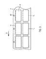
- Fig. 3 shows in a plan view of the lower film 4 each two troughs 8, which are arranged in two lanes, and a single-row clock or feed.
- the reference element 40 is located on the right edge of the lower film 4 seen in the direction of production R next to or outside the sealed seam 41.
- the cycle Tx before the sealing station 9 passes with a feed in the next cycle Ty in the sealing station.
- a tendency control for the forming station 5 is explained in more detail. If the controller 16 determines that the sealing station 9 has been adjusted several times in succession in the same direction, the forming station 5 can be displaced in the opposite direction by means of its own adjusting device in order to minimize or to increase the continuous adjustment of the sealing station 9 in only one direction break up.
- the adjustment of the sealing station 9 is used primarily to compensate for irregularities in the feed of the lower film 4 or irregularities in the lower film 4 itself by the position of the trough 8 is taken clock-accurate reference.
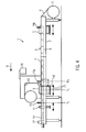
- Fig. 4 shows a variant of the invention in Fig. 1 Thermoforming packaging machine 1 shown.
- a device 14a for generating a reference element 40x, 40y is arranged in front of the forming station 5 and mechanically connected to the forming station 5.
- troughs 8 of a stroke Tx are deep-drawn simultaneously in the forming station, while the device 14a a reference element 40x integrally formed on the right edge of the lower film 4.
- the two adjacent troughs 8 of the clock Tx have a defined distance to the associated reference element 40x. This distance is input to the controller 16, and is charged in the detection of the reference element 40x in front of the sealing station 9 by means of a camera 15a in the controller 16 to position the sealing station 9 according to the troughs 8 of the clock Tx therein.
- Fig. 5 shows a plan view of the forming station of the inventive variant of Fig. 4 ,
- the device 14a forms a reference member 40x in the form of a nub of diameter For example, 3 mm in the lower film 4.
- troughs 8 of a clock Ty and a reference Elperent 40y were generated.
- the reference element 40x, 40y Since the respective reference element 40x, 40y has a distance A upstream of the troughs 8 in the production direction R, the reference element 40x, 40y can be detected outside or in front of the sealing station 9 after the associated troughs 8 are in the sealing station. The feed movement is completed and the wells 8 and the reference element 40x, 40y stand still.
- the camera 15a has a defined distance to the sealing station 9 and this distance can be entered into the controller 16 and is charged accordingly.
- a reference image of the reference element 40x, 40y is stored or learned in the camera 15a.
- a deviation of the current position of the reference element 40x, 40y relative to the reference image is charged together with the distance of the camera 15a to the sealing station 9 and the distance A of the reference element 40x to the wells 8 in the controller 16 and the sealing station 9 is positioned so that the ansch manend produced sealed seam 41 is in an exact position to the wells 8.
- the distance A may be, for example, the distance from the center of a circular nub deformation of the reference element 40x to the central axis of the troughs 8 of the clock Tx. But there are other alternative definitions of the distance A between the reference element 40x and troughs 8 of the clock Tx conceivable.
- the reference element 40x may have various shapes, preferably centric shapes such as a circle or a circular nub, which is formed upwards or downwards in the lower film 4. Punches are also conceivable, preferably circular punched holes.
Landscapes
- Engineering & Computer Science (AREA)
- Mechanical Engineering (AREA)
- Containers And Plastic Fillers For Packaging (AREA)
- Closing Of Containers (AREA)
Abstract
Description
- Die Erfindung bezieht sich auf eine Tiefziehverpackungsmaschine gemäß den Merkmalen des Anspruchs 1 und auf ein Verfahren zum Betrieb der Tiefziehverpackungsmaschine gemäß den Merkmalen des Anspruchs 10.
- Aus der
EP 0 569 933 A1 sind Tiefziehverpackungsmaschinen mit in Produktionsrichtung verstellbaren Arbeitsstationen, beispielsweise eine Form-, Siegel-, und Schneidstation, bekannt, die in Abhängigkeit der Position einer Druckmarke auf einer Unterfolie verstellt werden können, wobei die Druckmarke mittels eines Druckmarkensensors vor der Formstation erfasst wird. Die Arbeitsstationen weisen motorische Verstellantriebe mit Wegmesseinrichtungen auf. Sich veränderbare Abstände zwischen aufeinanderfolgenden Druckmarken werden mittels des Druckmarkensensors von der Steuerung ermittelt und die Position der Form-, Siegel- und Schneidstation entsprechend geregelt, um die Abstände der Arbeitsstationen untereinander anzupassen. Damit soll erreicht werden, dass die Formstation Mulden passend zur Position der Druckmarke formt, die Siegelstation Siegelnähte entsprechend der Lage der Mulden erzeugt und die Schneidstation die gesiegelten Packungen passend zu den Siegelnähten schneidet und die Packungen vereinzelt. - Eine Verstellung der Siegelstation nach Erfassen einer Druckmarke wirkt sich erst viele Vorschübe oder Vorzüge der erfassten Druckmarke später aus, da zwischen der Formstation und der Siegelstation eine Einlegestrecke zum Einlegen von zu verpackenden Produkten in die geformten Mulden vorgesehen ist. Dabei bleiben negative Einflüsse durch unregelmäßige Folienschrumpfung oder Toleranzen bei Vorschubbewegungen der Vorschubketten unberücksichtigt. Die Folge ist eine großzügige Auslegung der Breite der Packungsstege und -ränder in Vorschubrichtung, damit die Siegelnaht auf den Rändern mit einer ausreichenden Breite erzeugt werden kann und nach dem anschließenden Schneidvorgang die Siegelnaht noch eine Breite aufweist, um eine gewünschte Siegelqualität zu erreichen. Diese großzügige Auslegung führt zu einem erhöhten Folienverbrauch durch eine große Menge von Folienabfall.
- Aus der
DE 24 37 127 A1 ist eine weitere Verpackungsmaschine bekannt, bei der ein Druckmarkensensor für die Oberfolie verwendet wird. Dieser Druckmarkensensor ist genau so weit vor der Siegelstation angeordnet, wie auch die Formstation vor der Siegelstation angeordnet ist, sodass der Druckmarkensensor stets genau die Druckmarke erfasst, die dem Folienabschnitt entspricht, der zu der gerade im selben Maschinenzyklus geformten unteren Form gehört. - Die nicht vorveröffentliche
DE 10 2011 108 939 beschreibt ferner eine Verpackungsmaschine, bei der die Lage von Siegelnähten erfasst wird, um anschließend eine Schneideinrichtung passend zu der Lage der Siegelnähte ausrichten zu können. - Aufgabe der vorliegenden Erfindung ist es, eine Tiefziehverpackungsmaschine in Bezug auf den Folienverbrauch zu verbessern.
- Diese Aufgabe wird gelöst durch eine Tiefziehverpackungsmaschine mit den Merkmalen des Anspruchs 1 bzw. durch ein Verfahren zum Betrieb einer solchen Tiefziehverpackungsmaschine mit den Merkmalen des Anspruchs 10. Vorteilhafte Weiterbildungen der Erfindung sind in den Unteransprüchen angegeben.
- Die erfindungsgemäße Tiefziehverpackungsmaschine arbeitet im Betrieb mit einer bestimmten Vorschublänge pro Arbeitstakt. Sie umfasst eine Formstation zum Formen von Mulden in eine Unterfolie, eine Siegelstation, vorzugsweise eine Schneidstation und eine Steuerung, wobei die Siegelstation eine Verstelleinrichtung entlang einer Produktionsrichtung und eine Wegmesseinrichtung aufweist. Erfindungsgemäß ist an der Siegelstation oder innerhalb einer Vorschublänge vor der Siegelstation, d. h. innerhalb maximal einer Vorschublänge vor der Siegelstation, ein Messsystem zum Ermitteln der Lage des Referenzelements vorgesehen und die Steuerung ist dazu konfiguriert, die Siegelstation entsprechend der ermittelten Lage des Referenzelements zu den Mulden mittels der Verstelleinrichtung zu positionieren. Zum einen kann die Lage der Mulden ermittelt werden, die sich einen Takt vor der Siegelstation befinden oder zum anderen die Lage der Mulden, die sich bereits in der Siegelstation befinden, wenn die Vorschubbewegung der Unterfolie bzw. der Mulden abgeschlossen ist. Eine Ermittlung der Lage des Referenzelements bei einer stillstehenden Unterfolie bringt den Vorteil, dass Ungenauigkeiten in der Positionierung der Unterfolie bzw. der Mulden in die Siegelstation zum Ende der Vorschubbewegung hin berücksichtigt werden und Ungenauigkeiten einer dynamischen Erfassung des Referenzelements noch während der Vorschubbewegung eliminiert werden können. Die Lageregelung in der Endposition bei der Vorschubbewegung der Unterfolie mittels eines Servoantriebs kann vereinfacht werden, ebenso wie die Erfassung des Referenzelements.
- Dies bringt den Vorteil mit sich, dass die Siegelstation immer exakt in Bezug auf die Lage der zu siegelnden Mulden positioniert werden kann. Somit sind keine Toleranzen bezüglich Vorschubunterschieden mehr zu berücksichtigen und die für die Siegelung notwendige Fläche des Packungsrands kann auf ein Minimum reduziert werden. In Folge kann die Länge eines Folienvorschubs reduziert werden oder es können die Packungsabmessungen in Vorschubrichtung vergrößert werden, was zu einer Reduzierung des Folienabfalls führt.
- Bevorzugt ist das Messsystem zum berührungslosen Ermitteln der Lage des Referenzelements vorgesehen.
- Vorzugsweise weist die Formstation eine Vorrichtung auf oder die Vorrichtung ist vor (d.h. stromaufwärts) der Formstation angeordnet, um ein Referenzelement in die Unterfolie einzubringen, wobei mittels einer Erfassung des Referenzelements über das Messsystem die Lage der Mulden erfassbar ist. Die Vorrichtung ist bevorzugt mit der Formstation gekoppelt. Zum einen können die Formstation und die Vorrichtung mittels eines gemeinsamen Antriebs angetrieben werden, zum anderen weist das Referenzelement einen gegenüber den im selben Arbeitstakt geformten Mulden festgelegten und gleichbleibenden Abstand auf. Somit existiert ein fester Bezug zwischen der Lage der Mulden eines gemeinsamen Taktes und dem zugehörigen Referenzelement. Dies ermöglicht den Einsatz von kostengünstigen Messsystemen, da lediglich das Referenzelement erfasst werden muss, da die Mulden eine vorgegebene Lage zu dem Referenzelement aufweisen. Das Referenzelement kann beispielsweise eine durch die Vorrichtung, die Teil der Formstation ist, erzeugte Ausstanzung in Form eines Loches oder ein Prägen eines Noppens sein. Denkbar sind auch mehrere schmale Ausstanzungen, die z. B. beidseitig der Mulden nahe einer jeweils an beiden Seiten vorgesehenen Klammerkette zum Folientransport angebracht sind. Hierfür sind vor oder an der Siegelstation zwei Messsysteme vorgesehen, um solche Referenzelemente von beiden Seiten zu erfassen.
- Das Messsystem weist bevorzugt eine Kamera oder einen Reflextaster, beispielsweise eine Lichtschranke auf. Der Reflextaster ist vor allem geeignet, um ein Referenzelement in Form einer Ausstanzung erfassen zu können. Besonders zum Erfassen der Lage des Referenzelementes im Stillstand nach einer Vorschubbewegung der Unterfolie und damit der Mulden eignet sich die Kamera.
- Gemäß einer besonderen Ausführungsform ist die Wegmesseinrichtung der Siegelstation ein magnetostriktiver Lineargeber, um eine hygienegerechte Ausführung bereitzustellen. Ein solcher Lineargeber arbeitet berührungslos mit einem Messaufnehmer derart zusammen, dass selbst der Spalt zwischen Lineargeber und Messaufnehmer leicht reinigbar und beständig gegenüber üblichen Reinigungsmitteln ist.
- Bevorzugt ist ein Verstellweg der Siegelstation bis 1000 mm, vorzugsweise größer als 300 mm vorgesehen, um nicht nur Schwankungen in und entgegen der Produktionsrichtung auszugleichen, sondern beispielsweise die Siegelstation auch in eine Werkzeugwechselposition verfahren zu können, in der ein Siegelwerkzeugunter und/oder -oberteil seitlich oder nach oben aus der Tiefziehverpackungsmaschine zu Wartungs-, Reinigungs- oder Wechselzwecken entnehmbar ist.
- In einer vorteilhaften Ausführung ist ein weiteres Messsystem zum berührungslosen Ermitteln der Lage der Mulden, die in einem nächsten Arbeitstakt der Schneidstation zugeführt werden, vorgesehen und die Steuerung ist dazu konfiguriert, die Schneidstation entsprechend der ermittelten Lage der Mulden taktgenau in ihrer Position zu den Mulden mittels einer weiteren Verstelleinrichtung zu regeln. Dies stellt sicher, dass auch die Schneidstation taktgenau in Bezug auf die Lage der Mulden oder der in der Siegelstation erzeugten Siegelnähte positioniert werden kann. Denkbar ist bei einer direkt nach der Siegelstation angeordneten Schneidstation, dass die Steuerung die Schneidstation anhand der Erfassung der Mulden bzw. des oder der Referenzelemente positioniert.
- In einer weiteren besonderen Ausführungsform ist mittels der Steuerung eine Tendenzregelung für die Formstation vorgesehen. Der Begriff Tendenzregelung bedeutet, dass eine wiederholt nacheinander in nur eine Richtung ausgeführte Positionierung der Siegelstation von der Steuerung erkannt wird und dazu entgegensteuernd die Steuerung die Formstation so in der Gegenrichtung verstellt, dass eine weitere in eine Richtung fortlaufende Positionierung der Siegelstation vermieden werden kann.
- Vorzugsweise ist die Formstation und/oder die Siegelstation in eine Werkzeugwechselposition in oder gegen der Produktionsrichtung verfahrbar, um diese in eine bezogen auf die Tiefziehverpackungsmaschine seitlich zugängliche Position zu verstellen, um einen Werkzeugwechsel ergonomisch und ohne Einfluss auf eine Folie vornehmen zu können.
- Das erfindungsgemäße Verfahren zum Betrieb einer Tiefziehverpackungsmaschine, die eine Formstation zum Formen von Mulden in eine Unterfolie, eine Siegelstation und eine Steuerung umfasst, sieht vor, dass eine Vorrichtung ein Referenzelement in die Unterfolie einbringt und mittels eines Messsystems die Lage des Referenzelements und damit zumindest indirekt auch die Lage der Mulden ermittelt wird und die Steuerung mittels einer Verstelleinrichtung die Siegelstation in einer vorgegebenen bzw. vorgebbaren Position zu den Mulden positioniert. Zum einen kann die Lage der Mulden ermittelt werden, die sich einen Takt vor der Siegelstation befinden oder zum anderen die Lage der Mulden, die sich bereits in der Siegelstation befinden und die Vorschubbewegung abgeschlossen haben. Somit kann die Siegelstation immer exakt in Bezug auf die Lage der zu siegelnden Mulden positioniert werden und Toleranzen unberücksichtigt gelassen werden, welches zu einer Reduzierung des Folienverbrauchs führt.
- Das Messsystem erfasst vorzugsweise ein Referenzelement, das in die Unterfolie mittels einer Vorrichtung in der Formstation oder einer Vorrichtung, die vor der Formstation angeordnet ist, eingebracht wurde, um die Lage der Mulden in die Steuerung zu ermitteln.
- Die Steuerung ermittelt aus einer sich verändernden Lage der Mulden bevorzugt eine Tendenz und passt die Position der Formstation mittels einer weiteren Verstelleinrichtung in Bezug auf eine Produktionsrichtung an. Als Variante kann auch ein Parameter für die Länge der intermittierenden Vorschübe in der Steuerung angepasst werden.
- In einer besonderen Variante des erfindungsgemäßen Verfahrens erfasst die Steuerung mittels einer längs zur Produktionsrichtung ausgerichteten Wegmesseinrichtung der Verstelleinrichtung die Position der Siegelstation.
- Als eine weitere Variante zur berührungslosen Ermittlung der Lage der Mulden ist eine mechanische Abtasteinrichtung denkbar, um eine Ausstanzung oder einen Noppen als Referenzelement abzutasten.
- Bevorzugt erfasst eine Kamera die Lage des Referenzelements im Stillstand nach einer Vorschubbewegung der Unterfolie mittels einer Folientransportkette. Bei einer solchen Erfassung des Referenzelements im anschließenden Stillstand kann eine Berücksichtigung der Vorschubbewegung der Folientransportkette entfallen und dadurch die Genauigkeit der Positionierung der Siegelstation weiter erhöht werden. Ungenauigkeiten bzw. unterschiedliche Positionierungen der Folientransportkette, die durch unterschiedliche Reibungsverhältnisse entlang der Führungen der Folientransportkette auftreten, werden komplett berücksichtigt, da die Erfassung der Lage des Referenzelements und damit auch die Lage der Mulden erst anschließend an die Positionierung der Folientransportketten im Stillstand der zu versiegelnden Mulden durchgeführt wird.
- Denkbar ist auch die Möglichkeit, dass der Bediener Sollpositionen als Vorgabe für verschiedene Formwerkzeuge und damit auch mögliche unterschiedliche Vorschublängen in Programmen für die Prozesse in der Steuerung abzuspeichern.
- Im Folgenden wird ein vorteilhaftes Ausführungsbeispiel der Erfindung anhand einer Zeichnung näher erläutert. Im Einzelnen zeigen:
- Fig. 1
- eine erfindungsgemäße Tiefziehverpackungsmaschine in einer schematischen Seitenansicht,
- Fig. 2
- eine Teildarstellung einer Siegelstation in einer perspektivischen Ansicht,
- Fig. 3
- eine Draufsicht auf die Unterfolie vor, in und nach der Siegelstation,
- Fig. 4
- eine weitere Ausführung einer erfindungsgemäßen Tiefziehverpackungsmaschine in einer schematischen Seitenansicht und
- Fig. 5
- eine Draufsicht auf die Formstation.
- Gleiche Komponenten sind in den Figuren durchgängig mit gleichen Bezugszeichen versehen.
-
Fig. 1 zeigt eine erfindungsgemäße, taktweise arbeitende Tiefziehverpackungsmaschine 1 mit einem Maschinenrahmen 2, der entlang einer Produktionsrichtung R ausgerichtet ist. Am rechts in derFig.1 gezeigten Anfang der Tiefziehverpackungsmaschine 1 ist eine Abrollvorrichtung 3 für eine Unterfolie 4 vorgesehen. Die Unterfolie 4 wird mittels zweier nicht näher dargestellter Vorschubketten mit einer Vorschublänge V pro Arbeitstakt in Produktionsrichtung R einer Formstation 5 zugeführt. Des Weiteren ist eine Einlegestrecke 6 zum Einlegen eines Produkts 7 in geformte Mulden 8 stromabwärts nach der Formstation 5 gezeigt. Im weiteren Produktionsverlauf folgen eine Siegelstation 9 zum Verschließen der mit Produkt 7 gefüllten Mulden 8 mit einer Deckelfolie 10 und eine erste Schneidstation 11, die als Querschneidung ausgeführt ist. Eine zweite Schneideinrichtung 12, die nach der ersten Schneideinrichtung 11 stromabwärts angeordnet ist, ist als Längsschneidung ausgeführt und vereinzelt die Verpackungen 13. - Es können mehrere in Produktionsrichtung R geformte Mulden 8 in der Unterfolie angeordnet sein, die als Format mit beispielsweise drei nebeneinander angeordneten Mulden 8 um jeweils eine Mulde 8 in einem Takt intermittierend stromabwärts transportiert werden. Es ist aber ebenso denkbar, dass die Formstation 5 mehrere Reihen von Mulden 8 formt und jeweils dieses Format von Mulden 8, die in einem Arbeitstakt in der Formstation 5 in die Unterfolie 4 geformt werden, taktweise in Produktionsrichtung R weiter transportiert wird.
- Im Folgenden soll die Arbeitsweise der gezeigten Tiefziehverpackungsmaschine 1 näher erläutert werden. Die von der Abrollvorrichtung 3 abgerollte Unterfolie 4 wird von den Vorschubketten beidseitig erfasst und der Formstation 5 zugeführt. In der Formstation 5 werden eine oder mehrere Mulden 8 in die Unterfolie 4 geformt und in definierter Position relativ zu den Mulden 8 ein Referenzelement 40 (siehe
Fig. 3 ) mittels einer Stanzvorrichtung 14 in die Unterfolie 4 in einem Bereich eingebracht, der außerhalb der Mulden 8 und außerhalb oder zwischen später erzeugten Siegelnähten 41 liegt. Beispielsweise kann es sich bei dem Referenzelement 40 um ein Loch mit einem Durchmesser von 5 mm handeln. - Im nächsten Arbeitstakt wird die Unterfolie 4 mit den geformten Mulden 8 intermittierend entlang der Einlegestrecke 6 weitertransportiert. Dabei werden die Mulden 8 manuell oder automatisch beispielsweise mittels Pickern mit Produkten 7 gefüllt. In einem Takt Tx direkt vor Erreichen der Siegelstation 9, d. h. maximal eine Vorschublänge V vor der Siegelstation 9, ist ein Messsystem 15 oberhalb der Unterfolie 4 angebracht, um das Referenzelement 40 während der taktweisen Vorschubbewegung der Unterfolie 4 erfassen oder im Stillstand die Lage des Referenzelements 40 beispielsweise mittels einer Kamera 15a zu ermitteln.
- Die Information über die Lage des Referenzelements 40 im Takt Tx wird einer Steuerung 16 übermittelt. In der Steuerung 16 ist die Lage der Mulde 8 zum Referenzelement 40 hinterlegt, so dass die Steuerung 16 die Siegelstation 9 für den Takt Ty mittels einer Verstelleinrichtung 17 so verstellt, dass die Mulden 8, die im Takt Tx erfasst wurden, im folgenden Takt Ty in der Siegelstation 9 exakt mit dieser bezüglich ihrer Lage korrespondieren. Die Verstelleinrichtung 17 wird betätigt, nachdem der Siegelvorgang zum Ansiegeln der Deckelfolie 10 auf die Unterfolie 4 abgeschlossen wurde und sich ein Siegelwerkzeugunterteil 18 nach unten aus dem Kollisionsbereich der Mulden 8 entfernt hat, um die nächste Vorschubbewegung der Unterfolie 8 zuzulassen.
- Somit bezieht sich die Verstellung der Siegelstation 9 immer taktgenau auf die im Takt zuvor erfasste Lage der Mulden, da die Erfassung der Mulden 8 im Takt Tx eine Verstellung der Siegelstation 9 im direkt nachfolgenden Takt Ty zur Folge hat.
- Die Steuerung 16 kann zusätzlich zur Verstellung der Siegelstation 9 auch eine Verstellung der ersten Schneidstation 11 ausführen, um die Verpackungen 13 bzw. die Unterfolie 4 und die Deckelfolie 10 direkt an der Siegelnaht 41 quer zur Produktionsrichtung R ausgerichtet teilweise herauszutrennen. Hierzu kann die Erfassung der Mulden 8 im Takt Tx mittels des Messsystems 15 vor der Siegelstation 9 vorgesehen sein, oder ein weiteres Messsystem 19 im Takt Tz vor der Schneidstation 11 ermittelt die Lage der Mulden 8 oder der in der Siegelstation 9 erzeugten Siegelnähte 41 (siehe
Figur 3 ). Die zum Ende der Tiefziehverpackungsmaschine 1 angeordnete zweite Schneideinrichtung 12 ist als Längsschneidung ausgebildet und trennt die Verpackungen 13 längs zur Produktionsrichtung R aus, so dass die Verpackungen 13 vereinzelt dem weiteren Produktionsprozess zugeführt werden können. - In
Figur 2 ist die Siegelstation 9 ohne ein Siegelwerkzeugoberteil und das Siegelwerkzeugunterteil 18 dargestellt. Über sechs Befestigungselemente 20 ist die Siegelstation 9 am Maschinenrahmen 2 angebracht. Entlang von Führungsschienen 21 ist eine Hubeinrichtung 22 in und entgegen der Produktionsrichtung R bewegbar. Über einen Servoantrieb 23 und ein Riemengetriebe 24 ist die Hubeinrichtung 22 relativ zum Maschinenrahmen 2 mittels eines Zahnriemens 25 längs der Produktionsrichtung R verstellbar. Die Position der Siegelstation 9 bzw. der Hubeinrichtung 22 ist gegenüber dem Maschinenrahmen 2 über eine Wegmesseinrichtung 26 erfassbar, wobei die Wegmesseinrichtung 26 ein magnetostriktiver berührungslos arbeitender Lineargeber ist, der entlang des Maschinenrahmens 2 ausgerichtet ist. Ein zugehöriger Messaufnehmer 27 ist an der Hubeinrichtung 22 angebracht. Die Hubeinrichtung 22 weist ein Kniehebelhubwerk 28 mit einem Servoantrieb 29 auf, um das (nicht inFig. 2 dargestellte) Siegelwerkzeugunterteil 18, das auf den Aufnahmen 30 vorgesehen ist, vertikal anzuheben und abzusenken. -
Fig. 3 zeigt in einer Draufsicht auf die Unterfolie 4 jeweils zwei Mulden 8, die zweispurig angeordnet sind, und einen einreihigen Takt beziehungsweise Vorschub. Das Referenzelement 40 befindet sich am in Produktionsrichtung R gesehen rechten Rand der Unterfolie 4 neben bzw. außerhalb der Siegelnaht 41. Der Takt Tx vor der Siegelstation 9 geht mit einem Vorschub in den nächsten Takt Ty in der Siegelstation über. - Anhand der
Fig. 1 wird eine Tendenzregelung für die Formstation 5 näher erläutert. Stellt die Steuerung 16 fest, dass mehrmals hintereinander die Siegelstation 9 in die wiederholt gleiche Richtung verstellt wurde, so kann die Formstation 5 mittels einer eigenen Verstelleinrichtung in entgegengesetzter Richtung verstellt werden, um eine fortlaufende Verstellung der Siegelstation 9 in nur einer Richtung zu minimieren oder zu beenden. Die Verstellung der Siegelstation 9 dient in erster Linie dazu, Unregelmäßigkeiten im Vorschub der Unterfolie 4 oder Unregelmäßigkeiten in der Unterfolie 4 selbst auszugleichen, indem auf die Lage der Mulde 8 taktgenau Bezug genommen wird. -
Fig. 4 zeigt eine erfindungsgemäße Variante der inFig. 1 dargestellten Tiefziehverpackungsmaschine 1. Eine Vorrichtung 14a zum Erzeugen eines Referenzelements 40x, 40y ist vor der Formstation 5 angeordnet und mit der Formstation 5 mechanisch verbunden. In einem Arbeitstakt werden zugleich in der Formstation 5 Mulden 8 eines Taktes Tx tiefgezogen, während die Vorrichtung 14a ein Referenzelement 40x am rechten Rand der Unterfolie 4 einformt. Die zwei nebeneinander angeordneten Mulden 8 des Taktes Tx haben einen definierten Abstand zu dem zugeordneten Referenzelement 40x. Dieser Abstand ist in die Steuerung 16 eingebbar, und wird bei der Erfassung des Referenzelements 40x vor der Siegelstation 9 mittels einer Kamera 15a in der Steuerung 16 verrechnet, um die Siegelstation 9 entsprechend der darin befindlichen Mulden 8 des Taktes Tx zu positionieren. -
Fig. 5 zeigt eine Draufsicht auf die Formstation der erfindungsgemäßen Variante vonFig. 4 . In der Formstation 5 werden zwei Mulden 8 des Taktes Tx erzeugt und die Vorrichtung 14a formt ein Referenzelement 40x in Form einer Noppe mit einem Durchmesser von beispielsweise 3 mm in die Unterfolie 4. In einem zuvor stattgefunden Arbeitstakt wurden Mulden 8 eines Taktes Ty und ein Referenzelerpent 40y erzeugt. - Da das jeweilige Referenzelement 40x, 40y einen Abstand A stromaufwärts der Mulden 8 in Produktionsrichtung R aufweist, kann das Referenzelement 40x, 40y außerhalb bzw. vor der Siegelstation 9 erfasst werden, nachdem sich die zugehörigen Mulden 8 in der Siegelstation befinden. Dabei ist die Vorschubbewegung abgeschlossen und die Mulden 8 sowie das Referenzelement 40x, 40y stehen still. Die Kamera 15a hat einen definierten Abstand zur Siegelstation 9 und dieser Abstand kann in die Steuerung 16 eingegeben werden und wird entsprechend verrechnet. In der Kamera 15a wird ein Referenzbild des Referenzelements 40x, 40y hinterlegt bzw. eingelernt. Eine Abweichung der aktuellen Lage des Referenzelements 40x, 40y gegenüber dem Referenzbild wird zusammen mit dem Abstand der Kamera 15a zur Siegelstation 9 und dem Abstand A des Referenzelements 40x zu den Mulden 8 in der Steuerung 16 verrechnet und die Siegelstation 9 so positioniert, dass sich die anschießend erzeugte Siegelnaht 41 in einer exakten Lage zu den Mulden 8 befindet.
- Der Abstand A kann beispielsweise der Abstand vom Mittelpunkt einer kreisrunden Noppenverformung des Referenzelements 40x zur Mittelachse der Mulden 8 des Taktes Tx sein. Es sind aber weitere alternative Definitionen des Abstands A zwischen dem Referenzelement 40x und Mulden 8 des Taktes Tx denkbar.
- Das Referenzelement 40x kann verschiedene Formen aufweisen, vorzugsweise zentrische Formen wie ein Kreis bzw. eine kreisrunde Noppe, die nach oben oder unten in die Unterfolie 4 geformt ist. Denkbar sind auch Stanzungen, dabei bevorzugt kreisrunde Lochstanzungen.
Claims (13)
- Tiefziehverpackungsmaschine (1), umfassend eine Formstation (5) zum Formen von Mulden (8) in eine Unterfolie (4), eine Siegelstation (9) und eine Steuerung (16), wobei die Siegelstation (9) eine Verstelleinrichtung (17) für ein Verstellen ihrer Position entlang einer Produktionsrichtung (R) und eine Wegmesseinrichtung (26) aufweist, wobei die Tiefziehverpackungsmaschine (1) dazu eingerichtet ist, taktweise mit einer Vorschublänge (V) pro Arbeitstakt betrieben zu werden, dadurch gekennzeichnet, dass eine Vorrichtung (14a) zum Einbringen eines Referenzelements (40x, 40y) in die Unterfolie (4) vorgesehen ist, wobei an der Siegelstation (9) oder innerhalb einer Vorschublänge (V) stromaufwärts der Siegelstation (9) ein Messsystem (15a) zum Ermitteln der Lage des Referenzelements (40x, 40y) vorgesehen ist, wobei die Steuerung (16) dazu konfiguriert ist, die Position der Siegelstation (9) entsprechend der ermittelten Lage des Referenzelements (40x, 40y)zu den Mulden (8) mittels der Verstelleinrichtung (17) zu regeln.
- Tiefziehverpackungsmaschine nach Anspruch 1, dadurch gekennzeichnet, dass das Messsystem (15a) zum berührungslosen Ermitteln der Lage des Referenzelements (40x, 40y) vorgesehen ist.
- Tiefziehverpackungsmaschine nach einem der vorangehenden Ansprüche, dadurch gekennzeichnet, dass die Formstation (5) eine Vorrichtung (14a) aufweist oder eine Vorrichtung (14a) vor der Formstation (5) angeordnet ist, die konfiguriert ist um in definierter Lage relativ zu den Mulden (8) ein Referenzelement (40x, 40y) in die Unterfolie (4) einzubringen, wobei mittels einer Erfassung des Referenzelements (40x, 40y) über das Messsystem (15a) die Lage der Mulden (8) erfassbar ist.
- Tiefziehverpackungsmaschine nach einem der vorangehenden Ansprüche, dadurch gekennzeichnet, dass das Messsystem (15a) eine Kamera aufweist.
- Tiefziehverpackungsmaschine nach einem der vorangehenden Ansprüche, dadurch gekennzeichnet, dass die Wegmesseinrichtung (26) ein magnetostriktiver Lineargeber ist.
- Tiefziehverpackungsmaschine nach einem der vorangehenden Ansprüche, dadurch gekennzeichnet, dass ein Verstellweg der Siegelstation (9) bis 1000 mm vorgesehen ist.
- Tiefziehverpackungsmaschine nach einem der vorangehenden Ansprüche, dadurch gekennzeichnet, dass ein weiteres Messsystem (19) zum berührungslosen Ermitteln der Lage der Mulden (8), die in einem nächsten Arbeitstakt (Tz) der Schneidstation (11) zugeführt werden, vorgesehen ist und dass die Steuerung (16) dazu konfiguriert ist, die Schneidstation (11) entsprechend der ermittelten Lage der Mulden (8) taktgenau in ihrer Position zu den Mulden (8) mittels einer weiteren Verstelleinrichtung zu regeln.
- Tiefziehverpackungsmaschine nach einem der vorangehenden Ansprüche, dadurch gekennzeichnet, dass die Formstation (5) und/oder die Siegelstation (9) in eine Werkzeugwechselposition verfahrbar ist.
- Tiefziehverpackungsmaschine nach einem der vorangehenden Ansprüche, dadurch gekennzeichnet, dass die Steuerung (16) dazu konfiguriert ist, Sollpositionen der Formstation (5) und/oder der Siegelstation (9) in Rezepten in der Steuerung (16) einzugeben und abzuspeichern.
- Verfahren zum Betrieb einer Tiefziehverpackungsmaschine (1), die eine Formstation (5) zum Formen von Mulden (8) in eine Unterfolie (4), eine Siegelstation (9), und eine Steuerung (16) umfasst, dadurch gekennzeichnet, dass eine Vorrichtung (14a) ein Referenzelement (40x, 40y) in die Unterfolie (4) einbringt und mittels eines Messsystems (15a die Lage des Referenzelements (40x, 40y) ermittelt wird, wobei die Steuerung (16) mittels einer Verstelleinrichtung (17) die Siegelstation (9) in einer vorgegebenen Position zu dem Referenzelement (40x, 40y) positioniert.
- Verfahren nach Anspruch 10, dadurch gekennzeichnet, dass das Messsystem (15a) durch das Erfassen des Referenzelements (40x, 40y) eine Information bereitstellt, auf Grund derer die Steuerung (16) die Lage der Mulden (8) ermittelt.
- Verfahren nach Anspruch 10 oder 11, dadurch gekennzeichnet, dass das Referenzelement (40x, 40y) einen definierten und gleichbleibenden Abstand (A) gegenüber den Mulden (8) der zugehörigen Takte (Tx, Tx) hat.
- Verfahren nach einem der Ansprüche 10 bis 12, dadurch gekennzeichnet, dass die Steuerung (16) mittels einer längs zur Produktionsrichtung (R) ausgerichteten Wegmesseinrichtung (26) der Verstelleinrichtung (17) die Position der Siegelstation (9) erfasst.
Priority Applications (2)
| Application Number | Priority Date | Filing Date | Title |
|---|---|---|---|
| EP13002228.8A EP2740672B2 (de) | 2012-12-04 | 2013-04-26 | Tiefziehverpackungsmaschine mit taktgenauer Positionierung einer Siegelstation und entsprechendes Verfahren |
| US14/095,852 US20140150377A1 (en) | 2012-12-04 | 2013-12-03 | Thermo-forming packaging machine with true-to-cycle positioning of a sealing station |
Applications Claiming Priority (2)
| Application Number | Priority Date | Filing Date | Title |
|---|---|---|---|
| EP12008109.6A EP2740679B2 (de) | 2012-12-04 | 2012-12-04 | Tiefziehverpackungsmaschine mit taktgenauer Positionierung einer Siegelstation und entsprechendes Verfahren |
| EP13002228.8A EP2740672B2 (de) | 2012-12-04 | 2013-04-26 | Tiefziehverpackungsmaschine mit taktgenauer Positionierung einer Siegelstation und entsprechendes Verfahren |
Publications (3)
| Publication Number | Publication Date |
|---|---|
| EP2740672A1 true EP2740672A1 (de) | 2014-06-11 |
| EP2740672B1 EP2740672B1 (de) | 2016-12-07 |
| EP2740672B2 EP2740672B2 (de) | 2020-01-22 |
Family
ID=47429510
Family Applications (2)
| Application Number | Title | Priority Date | Filing Date |
|---|---|---|---|
| EP12008109.6A Active EP2740679B2 (de) | 2012-12-04 | 2012-12-04 | Tiefziehverpackungsmaschine mit taktgenauer Positionierung einer Siegelstation und entsprechendes Verfahren |
| EP13002228.8A Active EP2740672B2 (de) | 2012-12-04 | 2013-04-26 | Tiefziehverpackungsmaschine mit taktgenauer Positionierung einer Siegelstation und entsprechendes Verfahren |
Family Applications Before (1)
| Application Number | Title | Priority Date | Filing Date |
|---|---|---|---|
| EP12008109.6A Active EP2740679B2 (de) | 2012-12-04 | 2012-12-04 | Tiefziehverpackungsmaschine mit taktgenauer Positionierung einer Siegelstation und entsprechendes Verfahren |
Country Status (3)
| Country | Link |
|---|---|
| US (1) | US20140150377A1 (de) |
| EP (2) | EP2740679B2 (de) |
| ES (2) | ES2620763T5 (de) |
Cited By (6)
| Publication number | Priority date | Publication date | Assignee | Title |
|---|---|---|---|---|
| WO2019011448A1 (de) * | 2017-07-14 | 2019-01-17 | Multivac Sepp Haggenmüller Se & Co. Kg | Verfahren zum herstellen von verpackungen und tiefziehverpackungsmaschine |
| CN109414953A (zh) * | 2016-05-13 | 2019-03-01 | 鲍勃斯脱梅克斯股份有限公司 | 具有可置换工具的加工工件片材的加工装置 |
| US20190127101A1 (en) * | 2017-10-26 | 2019-05-02 | MULTIVAC Sepp Haggenmuller SE & Co. KG | Thermoform packaging machine and method of operating a thermoform packaging machine |
| DE102023135171A1 (de) | 2023-12-14 | 2025-06-18 | Multivac Sepp Haggenmüller Se & Co. Kg | Anpassung eines Vorschubparameters in einer Tiefziehverpackungsmaschine |
| DE102024117535A1 (de) * | 2024-06-21 | 2025-12-24 | Multivac Sepp Haggenmüller Se & Co. Kg | Positionsgenauer Materialvorschub in Verpackungsmaschine |
| US12583646B2 (en) | 2022-05-12 | 2026-03-24 | Weber Food Technology Se & Co. Kg | Separating unit |
Families Citing this family (16)
| Publication number | Priority date | Publication date | Assignee | Title |
|---|---|---|---|---|
| ITBO20130162A1 (it) * | 2013-04-12 | 2014-10-13 | Marchesini Group Spa | Metodo e sistema per sincronizzare una stazione di lavorazione di una macchina blisteratrice con l'avanzamento di un nastro blister |
| AR105231A1 (es) * | 2015-06-09 | 2017-09-20 | Cryovac Inc | Aparato y proceso para envasar productos |
| USD839938S1 (en) * | 2016-05-18 | 2019-02-05 | Bobst Mex Sa | Packaging machine |
| USD837849S1 (en) * | 2016-05-18 | 2019-01-08 | Bobst Mex Sa | Packaging machine |
| USD837850S1 (en) * | 2016-05-18 | 2019-01-08 | Bobst Mex Sa | Packaging machine |
| US10875670B2 (en) * | 2016-11-04 | 2020-12-29 | Alkar-Rapidpak, Inc. | Web-packaging machines with multiple sealing stations |
| DE102016122625A1 (de) | 2016-11-23 | 2018-05-24 | Multivac Sepp Haggenmüller Se & Co. Kg | Tiefziehverpackungsmaschine mit Zugvorrichtung |
| EP3428079B1 (de) * | 2017-07-14 | 2019-12-25 | MULTIVAC Sepp Haggenmüller SE & Co. KG | Tiefziehverpackungsmaschine mit flexibler packungsunterstützung |
| DE102018204044A1 (de) * | 2018-03-16 | 2019-09-19 | Multivac Sepp Haggenmüller Se & Co. Kg | Tiefziehverpackungsmaschine mit Folienumlenkung |
| US11891202B2 (en) * | 2018-05-18 | 2024-02-06 | Gea Food Solutions Germany Gmbh | Unwinding a film roll in a packaging machine |
| EP4566954A3 (de) | 2018-05-18 | 2026-02-25 | Gea Food Solutions Germany GmbH | Verfahren zur steuerung der lage der warenbahnkante |
| DE102018214666A1 (de) | 2018-08-29 | 2020-03-05 | Multivac Sepp Haggenmüller Se & Co. Kg | Verfahren zum Verpacken von Produkten und Tiefziehverpackungsmaschine |
| DE102019218756A1 (de) | 2019-12-03 | 2021-06-10 | Multivac Sepp Haggenmüller Se & Co. Kg | Tiefziehverpackungsmaschine und Verfahren zum Betreiben einer Tiefziehverpackungsmaschine |
| JP7459617B2 (ja) * | 2020-03-31 | 2024-04-02 | 大日本印刷株式会社 | 製袋機、製袋機の制御方法、および袋の製造方法 |
| DE102021126066A1 (de) | 2021-10-07 | 2023-04-13 | Multivac Sepp Haggenmüller Se & Co. Kg | Tiefziehverpackungsmaschine mit oberfolienträger |
| CN115320954B (zh) * | 2022-09-16 | 2024-05-17 | 合肥哈工龙延智能装备有限公司 | 一种新型智能化制托入托一体化设备 |
Citations (6)
| Publication number | Priority date | Publication date | Assignee | Title |
|---|---|---|---|---|
| GB1296251A (de) * | 1969-01-18 | 1972-11-15 | ||
| DE2437127A1 (de) | 1974-08-01 | 1976-02-19 | Multivac Hagenmueller Kg | Vakuumverpackungsmaschine zur herstellung versiegelter packungen aus einer ersten druckmarken aufweisenden und einer zweiten packstoffbahn |
| EP0569933A1 (de) | 1992-05-15 | 1993-11-18 | Multivac Sepp Haggenmüller Kg | Verpackungsmaschine mit bewegbaren Arbeitsstationen |
| DE20309826U1 (de) * | 2003-06-26 | 2004-11-04 | Finnah Engineering Und Packaging Gmbh | Maschine zum Abfüllen von Molkereiprodukten in Becher |
| DE202010004162U1 (de) * | 2010-03-24 | 2010-07-22 | Variovac Ps Systempack Gmbh | Verpackungsmaschine zur Herstellung von Packungen mit Packungsmarkierungen |
| DE102011108939A1 (de) | 2011-07-29 | 2013-01-31 | Multivac Sepp Haggenmüller Gmbh & Co. Kg | Verfahren zum Schneiden von Packungen |
Family Cites Families (21)
| Publication number | Priority date | Publication date | Assignee | Title |
|---|---|---|---|---|
| DE1815983B1 (de) * | 1968-12-20 | 1970-09-03 | Demag Ag | Vorrichtung zum automatischen Herstellen von Behaeltern,Behaelterunterteilen od.dgl. |
| US4773839A (en) | 1987-02-05 | 1988-09-27 | Amoco Corporation | Quick-change thermoformer |
| IT215984Z2 (it) | 1988-11-21 | 1991-03-26 | Gamma Srl | Dispositivo per il controllo della centratura di un nastro alveolato rispetto agli organi realizzanti la termosaldatura di un film allo stesso nastro alveolato |
| IT1235993B (it) † | 1989-12-29 | 1992-12-15 | Massimo Marchesini | Dispositivo perfezionato realizzante la termosaldatura di un film ad un nastro alveolato,in particolare nastro di polipropilene |
| DE4041547A1 (de) | 1990-01-30 | 1991-08-01 | Hassia Verpackung Ag | Tiefziehmaschine |
| DE4017923C1 (en) † | 1990-06-05 | 1991-02-21 | Hassia Verpackungsmaschinen Gmbh, 6479 Ranstadt, De | Thermoplastic films moulding machine - compensates for shrinkage of film and incorporates several work stations |
| DE69312899T2 (de) † | 1992-12-25 | 1997-12-11 | Ishida Scale Mfg Co Ltd | Vorrichtung zur Korrektur einer Zick-Zack-Bewegung einer langgestreckten laufenden Bahn |
| US6195967B1 (en) | 1998-11-03 | 2001-03-06 | Klockner Bartelt, Inc. | Packaging machine having continuous and intermittent modes |
| JP4053207B2 (ja) † | 2000-04-03 | 2008-02-27 | シーケーディ株式会社 | 成形充填密封打抜装置 |
| DE10065389A1 (de) * | 2000-11-24 | 2002-05-29 | Cfs Gmbh Kempten | Verfahren und Vorrichtung zum Positionieren von Folienbahnen einer Verpackungsvorrichtung |
| DE10117761A1 (de) | 2001-04-09 | 2002-10-17 | Bsh Bosch Siemens Hausgeraete | Verfahren und Vorrichtung zum Formen von Gegenständen aus einem Materialstrang und zum Vereinzeln der Gegenstände |
| US6777299B1 (en) | 2003-07-07 | 2004-08-17 | Taiwan Semiconductor Manufacturing Company, Ltd. | Method for removal of a spacer |
| US7249860B2 (en) | 2003-09-05 | 2007-07-31 | Donnelly Corporation | Interior rearview mirror assembly |
| US7172667B2 (en) | 2003-09-30 | 2007-02-06 | Tyco Healthcare Retail Services Ag | System and method for incorporating graphics into absorbent articles |
| DE102004020510B4 (de) | 2004-04-26 | 2007-11-29 | Edwin Kohl | Anlage zur Bestückung von Verpackungseinheiten mit dem verordnungsgemäßen Wochenbedarf von Patienten entsprechenden Medikamenten |
| DE102004025387B4 (de) † | 2004-05-17 | 2011-05-05 | Balluff Gmbh | Magnetostriktive Wegaufnehmervorrichtung |
| DE102005044537C5 (de) | 2005-09-17 | 2008-07-17 | Illig Maschinenbau Gmbh & Co. Kg | Thermoformmaschine und Verfahren zum lagegenauen Transportieren einer Folienbahn in dieser Thermoformmaschine |
| DE202007004908U1 (de) * | 2007-04-03 | 2007-06-14 | Poly-Clip System Gmbh & Co. Kg | Unsichtbare Druckmarkierung |
| DE102009049179B4 (de) * | 2009-10-13 | 2023-10-12 | Multivac Sepp Haggenmüller Se & Co. Kg | Verfahren und Verpackungsmaschine zum Verpacken von Produkten |
| JP5771449B2 (ja) | 2011-06-10 | 2015-08-26 | 株式会社イシダ | 製袋包装機 |
| EP2860119B1 (de) * | 2013-10-09 | 2016-08-31 | MULTIVAC Sepp Haggenmüller SE & Co. KG | Tiefziehverpackungsmaschine und Verfahren |
-
2012
- 2012-12-04 ES ES12008109T patent/ES2620763T5/es active Active
- 2012-12-04 EP EP12008109.6A patent/EP2740679B2/de active Active
-
2013
- 2013-04-26 EP EP13002228.8A patent/EP2740672B2/de active Active
- 2013-04-26 ES ES13002228T patent/ES2610583T5/es active Active
- 2013-12-03 US US14/095,852 patent/US20140150377A1/en not_active Abandoned
Patent Citations (6)
| Publication number | Priority date | Publication date | Assignee | Title |
|---|---|---|---|---|
| GB1296251A (de) * | 1969-01-18 | 1972-11-15 | ||
| DE2437127A1 (de) | 1974-08-01 | 1976-02-19 | Multivac Hagenmueller Kg | Vakuumverpackungsmaschine zur herstellung versiegelter packungen aus einer ersten druckmarken aufweisenden und einer zweiten packstoffbahn |
| EP0569933A1 (de) | 1992-05-15 | 1993-11-18 | Multivac Sepp Haggenmüller Kg | Verpackungsmaschine mit bewegbaren Arbeitsstationen |
| DE20309826U1 (de) * | 2003-06-26 | 2004-11-04 | Finnah Engineering Und Packaging Gmbh | Maschine zum Abfüllen von Molkereiprodukten in Becher |
| DE202010004162U1 (de) * | 2010-03-24 | 2010-07-22 | Variovac Ps Systempack Gmbh | Verpackungsmaschine zur Herstellung von Packungen mit Packungsmarkierungen |
| DE102011108939A1 (de) | 2011-07-29 | 2013-01-31 | Multivac Sepp Haggenmüller Gmbh & Co. Kg | Verfahren zum Schneiden von Packungen |
Cited By (8)
| Publication number | Priority date | Publication date | Assignee | Title |
|---|---|---|---|---|
| CN109414953A (zh) * | 2016-05-13 | 2019-03-01 | 鲍勃斯脱梅克斯股份有限公司 | 具有可置换工具的加工工件片材的加工装置 |
| US11731383B2 (en) | 2016-05-13 | 2023-08-22 | Bobst Mex Sa | Device having a changeable tool for processing workpiece sheets |
| WO2019011448A1 (de) * | 2017-07-14 | 2019-01-17 | Multivac Sepp Haggenmüller Se & Co. Kg | Verfahren zum herstellen von verpackungen und tiefziehverpackungsmaschine |
| US20190127101A1 (en) * | 2017-10-26 | 2019-05-02 | MULTIVAC Sepp Haggenmuller SE & Co. KG | Thermoform packaging machine and method of operating a thermoform packaging machine |
| US11008122B2 (en) * | 2017-10-26 | 2021-05-18 | Multivac Sepp Haggenmueller Se & Co. Kg | Thermoform packaging machine and method of operating a thermoform packaging machine |
| US12583646B2 (en) | 2022-05-12 | 2026-03-24 | Weber Food Technology Se & Co. Kg | Separating unit |
| DE102023135171A1 (de) | 2023-12-14 | 2025-06-18 | Multivac Sepp Haggenmüller Se & Co. Kg | Anpassung eines Vorschubparameters in einer Tiefziehverpackungsmaschine |
| DE102024117535A1 (de) * | 2024-06-21 | 2025-12-24 | Multivac Sepp Haggenmüller Se & Co. Kg | Positionsgenauer Materialvorschub in Verpackungsmaschine |
Also Published As
| Publication number | Publication date |
|---|---|
| EP2740679A1 (de) | 2014-06-11 |
| EP2740679B1 (de) | 2017-02-15 |
| ES2620763T5 (es) | 2020-07-17 |
| ES2610583T5 (es) | 2020-09-29 |
| EP2740672B2 (de) | 2020-01-22 |
| EP2740679B2 (de) | 2019-12-04 |
| US20140150377A1 (en) | 2014-06-05 |
| ES2620763T3 (es) | 2017-06-29 |
| ES2610583T3 (es) | 2017-04-28 |
| EP2740672B1 (de) | 2016-12-07 |
Similar Documents
| Publication | Publication Date | Title |
|---|---|---|
| EP2740672B1 (de) | Tiefziehverpackungsmaschine mit taktgenauer Positionierung einer Siegelstation und entsprechendes Verfahren | |
| EP2860119B1 (de) | Tiefziehverpackungsmaschine und Verfahren | |
| EP0616860B1 (de) | Presse mit einem Tafelanlage- und Vorschubsystem | |
| EP2896573B1 (de) | Tiefziehverpackungsmaschine mit Oberfolienformstation und entsprechendes Verfahren | |
| EP3202673B1 (de) | Tiefziehverpackungsmaschine | |
| EP2551203B1 (de) | Verfahren zum Schneiden von Packungen | |
| EP3793907B1 (de) | Verfahren zur steuerung der lage der warenbahnkante | |
| EP2517963B1 (de) | Verpackungsmaschine mit Transporteinrichtung | |
| EP3521185B1 (de) | Verfahren zum steuern des vorschubs einer folienbahn in einer verpackungsmaschine | |
| EP2574431A1 (de) | Komplettschnittstation und Verfahren zum Vereinzeln von Verpackungen | |
| DE60003301T2 (de) | Einheit zum Bearbeiten einer Verpackungsmaterialbahn für die Herstellung versiegelter Packungen mit fliessfähigen Nahrungsmitteln | |
| DE102008053591B4 (de) | Steuerungsverfahren für Stanzautomat | |
| EP3476753B1 (de) | Tiefziehverpackungsmaschine und verfahren zum betreiben einer tiefziehverpackungsmaschine | |
| EP3088315B2 (de) | Tiefziehverpackungsmaschine mit streifenstanze | |
| EP2213390A1 (de) | Verfahranlage für Stanzbleche | |
| DE202016000302U1 (de) | Tiefziehverpackungsmaschine | |
| DE102014103331B4 (de) | Steuerungsvorrichtung und -verfahren für eine Umreifungsmaschine | |
| DE102016203816B4 (de) | Vorrichtung zum Transport von Packmittel, insbesondere von Flaschen oder Bechern | |
| DE4345184C2 (de) | Tafelanlage- und Vorschubsystem für Pressen | |
| DE102016203814B4 (de) | Vorrichtung zum Transport von Packmittel, insbesondere von Flaschen oder Bechern | |
| DE602004008088T2 (de) | Verfahren zur kontrollierten förderung einer bahn | |
| DE102024117535A1 (de) | Positionsgenauer Materialvorschub in Verpackungsmaschine | |
| DE102023135171A1 (de) | Anpassung eines Vorschubparameters in einer Tiefziehverpackungsmaschine | |
| DE10161488B4 (de) | Verfahren und Vorrichtung zur Herstellung von Blechpaketen | |
| DE102019000963B4 (de) | Thermoformmaschine und Verfahren zur Herstellung von Formteilen |
Legal Events
| Date | Code | Title | Description |
|---|---|---|---|
| PUAI | Public reference made under article 153(3) epc to a published international application that has entered the european phase |
Free format text: ORIGINAL CODE: 0009012 |
|
| 17P | Request for examination filed |
Effective date: 20130426 |
|
| AK | Designated contracting states |
Kind code of ref document: A1 Designated state(s): AL AT BE BG CH CY CZ DE DK EE ES FI FR GB GR HR HU IE IS IT LI LT LU LV MC MK MT NL NO PL PT RO RS SE SI SK SM TR |
|
| AX | Request for extension of the european patent |
Extension state: BA ME |
|
| R17P | Request for examination filed (corrected) |
Effective date: 20141210 |
|
| RBV | Designated contracting states (corrected) |
Designated state(s): AL AT BE BG CH CY CZ DE DK EE ES FI FR GB GR HR HU IE IS IT LI LT LU LV MC MK MT NL NO PL PT RO RS SE SI SK SM TR |
|
| RAP1 | Party data changed (applicant data changed or rights of an application transferred) |
Owner name: MULTIVAC SEPP HAGGENMUELLER SE & CO. KG |
|
| GRAP | Despatch of communication of intention to grant a patent |
Free format text: ORIGINAL CODE: EPIDOSNIGR1 |
|
| INTG | Intention to grant announced |
Effective date: 20160718 |
|
| GRAS | Grant fee paid |
Free format text: ORIGINAL CODE: EPIDOSNIGR3 |
|
| GRAA | (expected) grant |
Free format text: ORIGINAL CODE: 0009210 |
|
| AK | Designated contracting states |
Kind code of ref document: B1 Designated state(s): AL AT BE BG CH CY CZ DE DK EE ES FI FR GB GR HR HU IE IS IT LI LT LU LV MC MK MT NL NO PL PT RO RS SE SI SK SM TR |
|
| REG | Reference to a national code |
Ref country code: GB Ref legal event code: FG4D Free format text: NOT ENGLISH |
|
| REG | Reference to a national code |
Ref country code: CH Ref legal event code: EP Ref country code: CH Ref legal event code: NV Representative=s name: BOVARD AG PATENT- UND MARKENANWAELTE, CH Ref country code: AT Ref legal event code: REF Ref document number: 851450 Country of ref document: AT Kind code of ref document: T Effective date: 20161215 |
|
| REG | Reference to a national code |
Ref country code: IE Ref legal event code: FG4D Free format text: LANGUAGE OF EP DOCUMENT: GERMAN |
|
| REG | Reference to a national code |
Ref country code: DE Ref legal event code: R096 Ref document number: 502013005627 Country of ref document: DE |
|
| PG25 | Lapsed in a contracting state [announced via postgrant information from national office to epo] |
Ref country code: LV Free format text: LAPSE BECAUSE OF FAILURE TO SUBMIT A TRANSLATION OF THE DESCRIPTION OR TO PAY THE FEE WITHIN THE PRESCRIBED TIME-LIMIT Effective date: 20161207 |
|
| REG | Reference to a national code |
Ref country code: NL Ref legal event code: FP |
|
| REG | Reference to a national code |
Ref country code: LT Ref legal event code: MG4D |
|
| REG | Reference to a national code |
Ref country code: FR Ref legal event code: PLFP Year of fee payment: 5 |
|
| PG25 | Lapsed in a contracting state [announced via postgrant information from national office to epo] |
Ref country code: NO Free format text: LAPSE BECAUSE OF FAILURE TO SUBMIT A TRANSLATION OF THE DESCRIPTION OR TO PAY THE FEE WITHIN THE PRESCRIBED TIME-LIMIT Effective date: 20170307 Ref country code: LT Free format text: LAPSE BECAUSE OF FAILURE TO SUBMIT A TRANSLATION OF THE DESCRIPTION OR TO PAY THE FEE WITHIN THE PRESCRIBED TIME-LIMIT Effective date: 20161207 Ref country code: SE Free format text: LAPSE BECAUSE OF FAILURE TO SUBMIT A TRANSLATION OF THE DESCRIPTION OR TO PAY THE FEE WITHIN THE PRESCRIBED TIME-LIMIT Effective date: 20161207 Ref country code: GR Free format text: LAPSE BECAUSE OF FAILURE TO SUBMIT A TRANSLATION OF THE DESCRIPTION OR TO PAY THE FEE WITHIN THE PRESCRIBED TIME-LIMIT Effective date: 20170308 |
|
| REG | Reference to a national code |
Ref country code: ES Ref legal event code: FG2A Ref document number: 2610583 Country of ref document: ES Kind code of ref document: T3 Effective date: 20170428 |
|
| PG25 | Lapsed in a contracting state [announced via postgrant information from national office to epo] |
Ref country code: HR Free format text: LAPSE BECAUSE OF FAILURE TO SUBMIT A TRANSLATION OF THE DESCRIPTION OR TO PAY THE FEE WITHIN THE PRESCRIBED TIME-LIMIT Effective date: 20161207 Ref country code: RS Free format text: LAPSE BECAUSE OF FAILURE TO SUBMIT A TRANSLATION OF THE DESCRIPTION OR TO PAY THE FEE WITHIN THE PRESCRIBED TIME-LIMIT Effective date: 20161207 Ref country code: FI Free format text: LAPSE BECAUSE OF FAILURE TO SUBMIT A TRANSLATION OF THE DESCRIPTION OR TO PAY THE FEE WITHIN THE PRESCRIBED TIME-LIMIT Effective date: 20161207 |
|
| PG25 | Lapsed in a contracting state [announced via postgrant information from national office to epo] |
Ref country code: IS Free format text: LAPSE BECAUSE OF FAILURE TO SUBMIT A TRANSLATION OF THE DESCRIPTION OR TO PAY THE FEE WITHIN THE PRESCRIBED TIME-LIMIT Effective date: 20170407 Ref country code: EE Free format text: LAPSE BECAUSE OF FAILURE TO SUBMIT A TRANSLATION OF THE DESCRIPTION OR TO PAY THE FEE WITHIN THE PRESCRIBED TIME-LIMIT Effective date: 20161207 Ref country code: SK Free format text: LAPSE BECAUSE OF FAILURE TO SUBMIT A TRANSLATION OF THE DESCRIPTION OR TO PAY THE FEE WITHIN THE PRESCRIBED TIME-LIMIT Effective date: 20161207 Ref country code: RO Free format text: LAPSE BECAUSE OF FAILURE TO SUBMIT A TRANSLATION OF THE DESCRIPTION OR TO PAY THE FEE WITHIN THE PRESCRIBED TIME-LIMIT Effective date: 20161207 Ref country code: CZ Free format text: LAPSE BECAUSE OF FAILURE TO SUBMIT A TRANSLATION OF THE DESCRIPTION OR TO PAY THE FEE WITHIN THE PRESCRIBED TIME-LIMIT Effective date: 20161207 |
|
| PG25 | Lapsed in a contracting state [announced via postgrant information from national office to epo] |
Ref country code: PT Free format text: LAPSE BECAUSE OF FAILURE TO SUBMIT A TRANSLATION OF THE DESCRIPTION OR TO PAY THE FEE WITHIN THE PRESCRIBED TIME-LIMIT Effective date: 20170407 Ref country code: SM Free format text: LAPSE BECAUSE OF FAILURE TO SUBMIT A TRANSLATION OF THE DESCRIPTION OR TO PAY THE FEE WITHIN THE PRESCRIBED TIME-LIMIT Effective date: 20161207 Ref country code: PL Free format text: LAPSE BECAUSE OF FAILURE TO SUBMIT A TRANSLATION OF THE DESCRIPTION OR TO PAY THE FEE WITHIN THE PRESCRIBED TIME-LIMIT Effective date: 20161207 Ref country code: BG Free format text: LAPSE BECAUSE OF FAILURE TO SUBMIT A TRANSLATION OF THE DESCRIPTION OR TO PAY THE FEE WITHIN THE PRESCRIBED TIME-LIMIT Effective date: 20170307 |
|
| REG | Reference to a national code |
Ref country code: DE Ref legal event code: R026 Ref document number: 502013005627 Country of ref document: DE |
|
| PLBI | Opposition filed |
Free format text: ORIGINAL CODE: 0009260 |
|
| PLAX | Notice of opposition and request to file observation + time limit sent |
Free format text: ORIGINAL CODE: EPIDOSNOBS2 |
|
| 26 | Opposition filed |
Opponent name: HARRO HOEFLIGER VERPACKUNGSMASCHINEN GMBH Effective date: 20170907 Opponent name: WEBER MASCHINENBAU GMBH BREIDENBACH Effective date: 20170907 |
|
| PG25 | Lapsed in a contracting state [announced via postgrant information from national office to epo] |
Ref country code: SI Free format text: LAPSE BECAUSE OF FAILURE TO SUBMIT A TRANSLATION OF THE DESCRIPTION OR TO PAY THE FEE WITHIN THE PRESCRIBED TIME-LIMIT Effective date: 20161207 Ref country code: DK Free format text: LAPSE BECAUSE OF FAILURE TO SUBMIT A TRANSLATION OF THE DESCRIPTION OR TO PAY THE FEE WITHIN THE PRESCRIBED TIME-LIMIT Effective date: 20161207 |
|
| REG | Reference to a national code |
Ref country code: IE Ref legal event code: MM4A |
|
| PG25 | Lapsed in a contracting state [announced via postgrant information from national office to epo] |
Ref country code: MC Free format text: LAPSE BECAUSE OF FAILURE TO SUBMIT A TRANSLATION OF THE DESCRIPTION OR TO PAY THE FEE WITHIN THE PRESCRIBED TIME-LIMIT Effective date: 20161207 |
|
| PLBB | Reply of patent proprietor to notice(s) of opposition received |
Free format text: ORIGINAL CODE: EPIDOSNOBS3 |
|
| PG25 | Lapsed in a contracting state [announced via postgrant information from national office to epo] |
Ref country code: LU Free format text: LAPSE BECAUSE OF NON-PAYMENT OF DUE FEES Effective date: 20170426 |
|
| REG | Reference to a national code |
Ref country code: BE Ref legal event code: MM Effective date: 20170430 |
|
| REG | Reference to a national code |
Ref country code: FR Ref legal event code: PLFP Year of fee payment: 6 |
|
| PG25 | Lapsed in a contracting state [announced via postgrant information from national office to epo] |
Ref country code: IE Free format text: LAPSE BECAUSE OF NON-PAYMENT OF DUE FEES Effective date: 20170426 |
|
| PG25 | Lapsed in a contracting state [announced via postgrant information from national office to epo] |
Ref country code: BE Free format text: LAPSE BECAUSE OF NON-PAYMENT OF DUE FEES Effective date: 20170430 |
|
| PG25 | Lapsed in a contracting state [announced via postgrant information from national office to epo] |
Ref country code: MT Free format text: LAPSE BECAUSE OF FAILURE TO SUBMIT A TRANSLATION OF THE DESCRIPTION OR TO PAY THE FEE WITHIN THE PRESCRIBED TIME-LIMIT Effective date: 20161207 |
|
| REG | Reference to a national code |
Ref country code: AT Ref legal event code: MM01 Ref document number: 851450 Country of ref document: AT Kind code of ref document: T Effective date: 20180426 |
|
| PG25 | Lapsed in a contracting state [announced via postgrant information from national office to epo] |
Ref country code: HU Free format text: LAPSE BECAUSE OF FAILURE TO SUBMIT A TRANSLATION OF THE DESCRIPTION OR TO PAY THE FEE WITHIN THE PRESCRIBED TIME-LIMIT; INVALID AB INITIO Effective date: 20130426 |
|
| PG25 | Lapsed in a contracting state [announced via postgrant information from national office to epo] |
Ref country code: AT Free format text: LAPSE BECAUSE OF NON-PAYMENT OF DUE FEES Effective date: 20180426 Ref country code: CY Free format text: LAPSE BECAUSE OF NON-PAYMENT OF DUE FEES Effective date: 20161207 |
|
| PG25 | Lapsed in a contracting state [announced via postgrant information from national office to epo] |
Ref country code: MK Free format text: LAPSE BECAUSE OF FAILURE TO SUBMIT A TRANSLATION OF THE DESCRIPTION OR TO PAY THE FEE WITHIN THE PRESCRIBED TIME-LIMIT Effective date: 20161207 |
|
| PUAH | Patent maintained in amended form |
Free format text: ORIGINAL CODE: 0009272 |
|
| STAA | Information on the status of an ep patent application or granted ep patent |
Free format text: STATUS: PATENT MAINTAINED AS AMENDED |
|
| REG | Reference to a national code |
Ref country code: CH Ref legal event code: AELC |
|
| 27A | Patent maintained in amended form |
Effective date: 20200122 |
|
| AK | Designated contracting states |
Kind code of ref document: B2 Designated state(s): AL AT BE BG CH CY CZ DE DK EE ES FI FR GB GR HR HU IE IS IT LI LT LU LV MC MK MT NL NO PL PT RO RS SE SI SK SM TR |
|
| REG | Reference to a national code |
Ref country code: DE Ref legal event code: R102 Ref document number: 502013005627 Country of ref document: DE |
|
| PG25 | Lapsed in a contracting state [announced via postgrant information from national office to epo] |
Ref country code: TR Free format text: LAPSE BECAUSE OF FAILURE TO SUBMIT A TRANSLATION OF THE DESCRIPTION OR TO PAY THE FEE WITHIN THE PRESCRIBED TIME-LIMIT Effective date: 20161207 |
|
| REG | Reference to a national code |
Ref country code: NL Ref legal event code: FP |
|
| PG25 | Lapsed in a contracting state [announced via postgrant information from national office to epo] |
Ref country code: AL Free format text: LAPSE BECAUSE OF FAILURE TO SUBMIT A TRANSLATION OF THE DESCRIPTION OR TO PAY THE FEE WITHIN THE PRESCRIBED TIME-LIMIT Effective date: 20161207 |
|
| REG | Reference to a national code |
Ref country code: ES Ref legal event code: DC2A Ref document number: 2610583 Country of ref document: ES Kind code of ref document: T5 Effective date: 20200929 |
|
| P01 | Opt-out of the competence of the unified patent court (upc) registered |
Effective date: 20230801 |
|
| PGFP | Annual fee paid to national office [announced via postgrant information from national office to epo] |
Ref country code: NL Payment date: 20250422 Year of fee payment: 13 |
|
| PGFP | Annual fee paid to national office [announced via postgrant information from national office to epo] |
Ref country code: DE Payment date: 20250417 Year of fee payment: 13 |
|
| PGFP | Annual fee paid to national office [announced via postgrant information from national office to epo] |
Ref country code: ES Payment date: 20250519 Year of fee payment: 13 |
|
| PGFP | Annual fee paid to national office [announced via postgrant information from national office to epo] |
Ref country code: IT Payment date: 20250430 Year of fee payment: 13 |
|
| PGFP | Annual fee paid to national office [announced via postgrant information from national office to epo] |
Ref country code: FR Payment date: 20250422 Year of fee payment: 13 |
|
| PGFP | Annual fee paid to national office [announced via postgrant information from national office to epo] |
Ref country code: CH Payment date: 20250501 Year of fee payment: 13 |
|
| PGFP | Annual fee paid to national office [announced via postgrant information from national office to epo] |
Ref country code: GB Payment date: 20260324 Year of fee payment: 14 |