EP2871005B1 - Dispositif de formage pour la déformation plastique d'un composant et procédé de formage d'un composant - Google Patents
Dispositif de formage pour la déformation plastique d'un composant et procédé de formage d'un composant Download PDFInfo
- Publication number
- EP2871005B1 EP2871005B1 EP13192503.4A EP13192503A EP2871005B1 EP 2871005 B1 EP2871005 B1 EP 2871005B1 EP 13192503 A EP13192503 A EP 13192503A EP 2871005 B1 EP2871005 B1 EP 2871005B1
- Authority
- EP
- European Patent Office
- Prior art keywords
- component
- bending
- bending rail
- forming device
- area
- Prior art date
- Legal status (The legal status is an assumption and is not a legal conclusion. Google has not performed a legal analysis and makes no representation as to the accuracy of the status listed.)
- Active
Links
Images

Classifications
-
- B—PERFORMING OPERATIONS; TRANSPORTING
- B21—MECHANICAL METAL-WORKING WITHOUT ESSENTIALLY REMOVING MATERIAL; PUNCHING METAL
- B21D—WORKING OR PROCESSING OF SHEET METAL OR METAL TUBES, RODS OR PROFILES WITHOUT ESSENTIALLY REMOVING MATERIAL; PUNCHING METAL
- B21D5/00—Bending sheet metal along straight lines, e.g. to form simple curves
- B21D5/04—Bending sheet metal along straight lines, e.g. to form simple curves on brakes making use of clamping means on one side of the work
- B21D5/042—With a rotational movement of the bending blade
Definitions
- the invention relates to a forming device for plastic deformation of a component, in particular a sheet metal component according to the preamble of claim 1. Furthermore, the invention relates to a method for forming a component, using the inventive unforming device.
- a forming device for plastic deformation of a component in particular a sheet metal component according to the preamble of claim 1.
- the invention relates to a method for forming a component, using the inventive unforming device.
- From the DE 10 2005 018 866 B3 is a generic device for bending or folding of an object, in particular a formed as a sheet metal part, known, which has means for clamping the object to be processed and a movable bending device.
- the local means comprise a trained as a top beam upper part, a lower part and a movable bending cheek of the bending device.
- the movable bending cheek is formed in two parts, wherein the two parts of the bending cheek are connected to each other by means of respective, designed as screws or bolts coupling elements and movable relative to each other.
- a warping of a bending rail designed as a crowning element can be set, wherein the bending rail is arranged on one of the two parts.
- the warping of the bending rail to compensate for any unwanted angular deviations on the component is now present in that due to the relative movement of the two parts to each other, the part on which the bending rail is arranged, is warped and thereby the bending rail is subjected to this warping.
- a component to be deformed is then inserted between the upper part and the bending rail of the lower part and deformed under a relative movement between the upper part and the lower part, or bent.
- the two parts of the bending cheek are made with high manufacturing costs particularly precise and matched exactly by means of the respective coupling elements.
- a forming machine which comprises a tool frame on both sides held and relatively movable tool carrier with a tool holder in a positionally variable recorded tool.
- the tool carrier is equipped over its length with a plurality of actuating elements which act on the tool from a side facing away from the workpiece.
- Each actuating element in this case comprises a hydraulic cylinder, wherein the hydraulic cylinders are hydraulically connected to each other such that during a forming process, a substantially uniform contact pressure on a workpiece is set along the tool.
- the EP 0 934 131 B1 discloses a bending machine for flat material, with a machine frame, on which a lower cheek with lower cheek tool and a top cheek with Oberwangenwerkmaschine is arranged.
- the upper and lower cheeks are movable relative to each other for fixing and bending the sheet.
- the bending machine also includes a bending cheek having a be equipped with a bending beam tool Biegegewangentechnikmaschinemaschineability and which is held about a rotation axis pivotally mounted on the machine frame.
- the bending cheek tool holder is provided with an adjustable crowning device which, viewed in the bending direction, supports one foot of the bending beam tool only in one subarea, so that the foot bears on a rear abutment surface of the bending cheek tool holder when bending forces occur.
- the bending rail has a slot which spaces the first region from the second region over at least a substantial portion of a longitudinal extension of the bending rail and the bending rail comprises at least one recess between the first region and the second region in which the deformation component is arranged is.
- the bending rail is elastically deformable in itself, wherein at least the first region can be arched and additionally or alternatively, the second region is subjected to a curvature.
- a higher degree of freedom is created in the warping of the first region of the bending rail and thus its edge.
- any angular deviations of a bending angle can be compensated, if e.g. the bending of the upper part of the forming device - for example, as a result of asymmetric stiffening struts or material accumulations or material inhomogeneities of the upper or lower part of the forming device or the component - takes place off-center during forming.
- the edge of the first region of the bending rail could not only be concave or convex, but also, for example, wave-shaped elastically deformed in order to compensate for corresponding deviations.
- the bending rail characterized in that it comprises at least one deformation component and thus in itself is partially elastically deformable, formed as a so-called barbed bending rail.
- the component to be formed is designed, for example, as a metal sheet, a respective different springback behavior of the bent metal sheet over the entire working width of the shaping device or the length of the bending rail can be compensated by means of the bightable bending rail. Since it is a particularly inexpensive and easy to manufacture component of the forming device in the bending rail, a particularly economical way is also created to compensate for deviations along the bending line.
- the bending rail By arranging the deformation components in the recess, the bending rail can be made particularly compact. By such an arrangement, the bending rail can also be designed to save space. By a corresponding contouring of the recess, the elastic deformability of the bending rail can be influenced. If the recess is generously dimensioned and correspondingly much material is removed from the bending rail, the distance between the edge of the recess and the edge of the bending rail is reduced. Thus, a greater deformation of the bending rail can be made possible, or less force is required for a deformation of the bending rail.
- the recess is dimensioned to be particularly small, more material remains in the area between the edge and the recess on the bending rail, which makes it particularly stiff and resistant to a force acting on the component side when it is deformed.
- an efficient and economical way is created in a particularly simple manner to buckle the edge of the bending rail according to the respective requirements.
- the deformation component comprises a first component and a second component, which are movable relative to each other.
- first component and the second components By using the first component and the second components, any undesired plastic deformations on the bending rail can be prevented in a particularly effective manner, in particular if the first component and the second component are designed as pressure-distributing shell elements.
- the first component and the second component are moved apart by applying a pressure, thereby causing the deformation of the bending rail.
- the pressure exerted by the deformation component and the bending rail partially elastically deforming pressure is then distributed by the first component and the second component particularly evenly on the bending rail, whereby elastic deformation of the bending rail due to impermissibly high pressure peaks can be particularly effectively prevented.
- the first component and the second component of the deformation component are movable relative to one another by means of an eccentric part.
- the eccentric part which is arranged between the first component and the second component
- the deformation component is infinitely adjustable and, accordingly, the elastic deformation of the bending rail can be adjusted particularly precisely.
- the first and second components can be moved relative to each other by exerting a particularly high deformation force or by traversing a particularly large deformation path.
- first region and / or the second region of the bending rail is movable as a function of the relative movement between the first component and the second component of the deformation component.
- An elastic deformation of the bending bar is correspondingly particularly intuitive by the forming device operating personnel possible if associated with a relative movement of the first component to the second components of the deformation component and an elastic deformation of the bending bar. This applies in particular when, with an increase in the distance between the first component and the second component, a greater elastic deformation of the bending rail takes place, whereby ergonomically speaking, a particularly intuitive operation of the forming device is made possible.
- the bending rail is integrally formed. Since the production costs, in particular of precision components increase with the number of individual components of which the respective component is composed, a one-piece design of the bending rail is particularly resource-friendly.
- the bending rail comprises respective cover plates for guided relative movement between the first and the second region.
- cover plates can be particularly efficient prevented any lateral bending of the first region relative to the second region or vice versa.
- cover plates therefore, a particularly exact movement, which essentially extends in one plane, can be realized between the first region and the second region.
- a warping of the bending rail in an undesired spatial direction is accordingly particularly effectively prevented.
- the forming device is designed as a folding machine. Swivel bending machines are particularly suitable for reshaping components which are designed as metal sheets with large thicknesses with great precision.
- the bending bar can be adapted to the rigidity of the pivoting bending machine with particularly little effort and, accordingly, can compensate deviations of a long bending line particularly effectively.
- an adjustment takes place respective predefined deformation parameters by means of at least one deformation component.
- the deformation component at least one of the component facing and at least partially an edge forming first region of a first region and a second region having bending rail is elastically deformed at least partially.
- the forming of the component takes place under the relative movement between the lower part and the upper part of the shaping device by exerting a deformation force by the intermediary of the bending rail.
- the bending rail is elastically deformed in dependence of respective geometry sizes of the component by means of the deformation component.
- geometry sizes include, for example, the length, the width or the depth at the location of the component at which the transformation is to take place.
- the deformation of the component, or the suitability of the component for a slight or substantial deformation thus depends on such dimensions, for example, the depth, so the material thickness of the component influences the maximum possible bending radius or the bending angle.
- the clamping means ie the upper part and, additionally or alternatively, the lower part of the shaping device, are subjected to particularly high local stress locally and, if necessary, during the component deformation itself elastically deformed. This can be effectively compensated by the crowning, so the elastic deformation of the bending rail.
- the bending bar is elastically deformed by means of the deformation component as a function of respective parameters relating to the strength of the component.
- the strength of the component includes in particular material properties that influence the forming process. Such material properties include, for example, the modulus of elasticity or notched impact strength of the component. Further parameters which relate to the strength of the component are, for example, the concentration of alloy constituents or a possible hardening process to which the component has been subjected or a specific hardening depth which was previously selected in the corresponding hardening process of the component to be formed.
- the advantages and preferred embodiments described for the forming device according to the invention also apply to the method according to the invention and vice versa.
- the device according to the invention can be used.
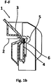
- Fig. 1 a shows a front view of a forming device 1 designed as a folding machine, which comprises a top part 3 designed as a top beam and a bottom part 4.
- a bending rail 6 is arranged, wherein - as from a in Fig. 1b illustrated sectional view according to a section line FF Fig. 1 a - it can be seen that a reshaping component 2, which is presently designed as a metal sheet, between the upper part 3 and the bending rail 6 of the lower part 4 is fixed.
- the lower part 4 As well as the bending rail 6 arranged on the lower part 4 are pivoted so far relative to the upper part 3 in accordance with a relative movement 5 marked with a double arrow, until the component has been bent in accordance with the desired bending angle or Bend radius bent and accordingly plastically deformed.
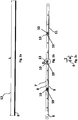
- Fig. 2a shows a plan view and Fig. 2b a front view of the bending rail 6.
- the bending rail 6 has a longitudinal extent 12 of length L and, as in a side view of the bending rail 6 in Fig. 2c is recognizable, a width B and a depth T on.
- the bending rail 6 has an at least partially an edge 7 forming first region 8 and a second region 9, wherein the bending rail 6 is arranged in the forming device 1 such that the first region 8 faces the component to be formed 2, and accordingly the edge 7th rests against the component 2.
- the bending rail 6 further comprises in the present case a plurality of deformation components 10, by means of which the first region 8 is at least partially elastically deformable.
- the bending rail 6 likewise has a slot 11 which spaces the first area 8 from the second area 9 at least over a substantial area of the longitudinal extension 12 of the bending rail 6. In other words, therefore, the slot 11 of the bending rail 6 extends over a large part of the length L of the bending rail 6.
- the deformation components 10 are arranged in respective recesses 13 of the bending rail, wherein the recesses 13 are surrounded by the first region 8 and the second region 9 , In the present case, the recesses 13 are thus arranged between the first region 8 and the second region 9.
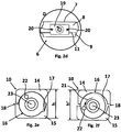
- Fig. 2d shows an enlarged view of an in Fig. 2b with D marked section, it being understood that the bending rail 6 includes respective cover plates 19.
- the Cover plates 19 serve to stabilize the bending rail 6 and allow elastic deformation by means of the respective deformation components 10 such that, although the width B (FIG. Fig. 2c ) of the bending rail 6 along its longitudinal extension 12 and thus along its length L can change, but a lateral warping between the first region 8 and the second region 9 is effectively prevented.
- cover plates 19 In order to fix the cover plates 19 particularly securely on the bending rail 6, they are presently screwed to the bending rail 6 by means of respective screws 20, which are designed as countersunk screws.
- the screws 20 are presently extending parallel to the longitudinal extent 12 and arranged on opposite sides of the respective cover plate 19.
- the bending rail 6 is present in one piece and accordingly made particularly resource-friendly.
- Fig. 2e and Fig. 2f each show an enlarged front view of the deformation component 10, wherein Fig. 2e shows a position of the deformation component 10, in which no deformation of the bending rail 6 takes place and Fig. 2f a position in which at least partially an elastic deformation of the bending rail 6 takes place.
- the deformation component 10 comprises a first component 14 and a second component 15, wherein the first component 14 and the second component 15 are formed as respective eccentric bearing shells and movable relative to each other. Between the first component 14 and the second component 15, an eccentric part 16 designed as an eccentric shaft is arranged, which has an eccentricity 17.
- Fig. 2e shows a position of the deformation component 10, in which no deformation of the bending rail 6 takes place
- Fig. 2f a position in which at least partially an elastic deformation of the bending rail 6 takes place.
- the deformation component 10 comprises a first component 14 and a second component 15, wherein the first component 14 and the second component 15 are formed as respective eccentric bearing shells and
- the eccentricity 17 runs parallel to the longitudinal extension 12 or to the slot 11 of the bending rail 6, whereby a gap 18, which is formed between the first component 14 and the second component 15, has a minimum value and, accordingly, a height of the respective deformation component 10, which by the first component 14, the second component 15 and the eccentric 16 is formed having the value h.
- the extension of the height with the value h in Fig. 2e extends in the same direction as the width B of the bending bar 6 and thus substantially perpendicular to the longitudinal extent 12.
- the eccentric 16 is rotatably mounted by means of tool engagement in an eccentric to a rotational axis 23 of the eccentric 16 and in the present case designed as a hexagon fixation opening 22 about the rotation axis 23.
- the deformation force and thus also the height change of the deformation component 10 is transferred from the value h to the value h 'on the bending rail 6.
- the bending rail 6 is deformed elastically at least in some areas, specifically at those regions of the bending rail 6 in which a change in the height of the deformation component 10 takes place.
- the first region 8 and, additionally or alternatively, the second region 9 of the bending rail 6 as a function of the relative movement between the first component 14 and the second component 15 of the deformation component 10 movable.
- the first component 14 and the second component 15 could be dispensed with and the eccentric part 16 could abut directly on the first region 8 and additionally or alternatively on the second region 9.
- the eccentric part 16 would then be in direct contact with the first region 8 and the second region 9 of the bending rail 6.
- the slot 11 and, consequently, the first area 8 of the bending bar 6 or its edge 7 would then buckle directly due to its eccentricity 17.
Landscapes
- Engineering & Computer Science (AREA)
- Mechanical Engineering (AREA)
- Bending Of Plates, Rods, And Pipes (AREA)
Claims (10)
- Dispositif de formage (1), destiné à la déformation plastique d'un composant (2), en particulier d'un composant de tôle, lequel peut être fixé entre une partie supérieure (3) et une partie inférieure (4) du dispositif de formage (1), comprenant un rail de pliage (6) et peut être déformé avec un mouvement relatif (5) entre la partie inférieure (4) et la partie supérieure (3) du dispositif de formage (1), le rail de pliage (6) comprenant au moins une première zone (8), tournée vers le composant (2) et constituant au moins par zones une arête (7), ainsi qu'une seconde zone (9) et de plus au moins un composant de déformation (10), au moyen duquel au moins la première zone (8) peut être déformée élastiquement au moins par zones,
caractérisé en ce que
le rail de pliage (6) présente une fente (11), laquelle éloigne la première zone (8) de la seconde zone (9) au moins par l'intermédiaire d'une zone essentielle d'une extension longitudinale (12) du rail de pliage (6) et le rail de pliage (6) comprend au moins un évidement (13) entre la première zone (8) et la seconde zone (9), dans lequel est agencé le composant de déformation (10). - Dispositif de formage (1) selon la revendication 1,
caractérisé en ce que
le composant de déformation (10) comprend un premier composant (14) et un second composant (15), qui sont mobiles l'un par rapport à l'autre. - Dispositif de formage (1) selon la revendication 2,
caractérisé en ce que
le premier composant (14) et le second composant (15) du composant de déformation (10) sont mobiles l'un par rapport à l'autre au moyen d'une partie excentrique (16). - Dispositif de formage (1) selon l'une des revendications 2 ou 3, caractérisé en ce que
la première zone (8) et / ou la seconde zone (9) du rail de pliage (6) sont mobiles en fonction du mouvement relatif entre le premier composant (14) et le second composant (15) du composant de déformation (10). - Dispositif de formage (1) selon l'une des revendications précédentes,
caractérisé en ce que
le rail de pliage (6) est constitué d'un seul bloc. - Dispositif de formage (1) selon l'une des revendications précédentes,
caractérisé en ce que
le rail de pliage (6) comprend des tôles de recouvrement (19) respectives, destinées au mouvement relatif guidé entre la première zone (8) et la seconde zone (9). - Dispositif de formage (1) selon l'une des revendications précédentes,
caractérisé en ce que
le dispositif de formage (1) est constitué en tant que machine de pliage. - Procédé de formage d'un composant (2) au moyen d'un dispositif de formage (1), comprenant une partie supérieure (3) et une partie inférieure (4), pour lequel le composant (2) est fixé entre la partie supérieure (3) et un rail de pliage (6), affecté à la partie inférieure (4) et est déformé avec un mouvement relatif (5) entre la partie inférieure (4) et la partie supérieure (3) du dispositif de formage (1),
caractérisé par les étapes suivantes consistant à :- régler des paramètres de déformation prédéfinis respectifs au moyen au moins d'un composant de déformation (10), au moyen duquel au moins une première zone (8), tournée vers le composant (2) et constituant au moins par zones une arête (7), d'un rail de pliage (6) présentant la première zone (8), ainsi qu'une seconde zone (9), est déformée élastiquement au moins par zones et- former le composant (2) avec le mouvement relatif (5) entre la partie inférieure (4) et la partie supérieure (3) du dispositif de formage (1) en exerçant une force de déformation par l'intermédiaire du rail de pliage (6),- un dispositif de formage (1) étant utilisé conformément à l'une des revendications 1 à 7 pour exécuter le procédé. - Procédé selon la revendication 8,
caractérisé en ce que
le rail de pliage (6) est déformé élastiquement au moyen du composant de déformation (10), en fonction de grandeurs géométriques respectives du composant (2). - Procédé selon la revendication 8,
caractérisé en ce que
le rail de pliage (6) est déformé élastiquement au moyen du composant de déformation (10), en fonction de paramètres respectifs, concernant la résistance du composant (2).
Priority Applications (1)
| Application Number | Priority Date | Filing Date | Title |
|---|---|---|---|
| EP13192503.4A EP2871005B1 (fr) | 2013-11-12 | 2013-11-12 | Dispositif de formage pour la déformation plastique d'un composant et procédé de formage d'un composant |
Applications Claiming Priority (1)
| Application Number | Priority Date | Filing Date | Title |
|---|---|---|---|
| EP13192503.4A EP2871005B1 (fr) | 2013-11-12 | 2013-11-12 | Dispositif de formage pour la déformation plastique d'un composant et procédé de formage d'un composant |
Publications (2)
| Publication Number | Publication Date |
|---|---|
| EP2871005A1 EP2871005A1 (fr) | 2015-05-13 |
| EP2871005B1 true EP2871005B1 (fr) | 2016-05-25 |
Family
ID=49641487
Family Applications (1)
| Application Number | Title | Priority Date | Filing Date |
|---|---|---|---|
| EP13192503.4A Active EP2871005B1 (fr) | 2013-11-12 | 2013-11-12 | Dispositif de formage pour la déformation plastique d'un composant et procédé de formage d'un composant |
Country Status (1)
| Country | Link |
|---|---|
| EP (1) | EP2871005B1 (fr) |
Family Cites Families (5)
| Publication number | Priority date | Publication date | Assignee | Title |
|---|---|---|---|---|
| DE19735793C2 (de) * | 1997-08-18 | 2001-07-12 | Wolfram Hochstrate | Schwenkbiegemaschine |
| DE19736987A1 (de) * | 1997-08-26 | 1999-03-11 | Reinhardt Gmbh Maschbau | Biegemaschine |
| DE102005018866B3 (de) | 2005-04-22 | 2006-05-24 | Schechtl Maschinenbau Gmbh | Vorrichtung und Verfahren zum Biegen oder Abkanten eines Gegenstands, insbesondere eines Blechteils |
| DE102006047108B4 (de) * | 2006-09-27 | 2009-09-10 | Ras Reinhardt Maschinenbau Gmbh | Biegemaschine zum Biegen von Flachmaterial |
| DE102008025351A1 (de) * | 2008-05-27 | 2009-12-03 | Hans Schröder Maschinenbau GmbH | Umformmaschine |
-
2013
- 2013-11-12 EP EP13192503.4A patent/EP2871005B1/fr active Active
Also Published As
| Publication number | Publication date |
|---|---|
| EP2871005A1 (fr) | 2015-05-13 |
Similar Documents
| Publication | Publication Date | Title |
|---|---|---|
| EP2712702B1 (fr) | Dispositif de finition de bande, système de finition de bande et procédé de fabrication d'un dispositif de finition de bande | |
| EP3263241B1 (fr) | Dispositif de repliage à rouleaux et procédé de repliage d'une zone de rebord d'une pièce de tôlerie | |
| EP3052256B1 (fr) | Presse à plier et procédé de pliage | |
| DE102012108280A1 (de) | Rundbiegevorrichtung | |
| DE102007012316B4 (de) | Verfahren und Anbiegepresse zum Anbiegen der Randstreifen eines zu einem Schlitzrohr zu formenden ebenen Bleches | |
| DE102007062104B4 (de) | Vorrichtung für einen Rollformer zum Profilieren eines Blechbandes und dazugehöriges Verfahren | |
| DE19839614B4 (de) | Metallbandbiegerollverfahren zur Herstellung eines elektrisch zu schweißenden Rohres aus einem flachen Metallband | |
| EP2077166B1 (fr) | Dispositif de traitement de bord longitudinal pour tôles | |
| EP2435198B1 (fr) | Serre-flan flexible pour installations de profilage continu | |
| EP2871005B1 (fr) | Dispositif de formage pour la déformation plastique d'un composant et procédé de formage d'un composant | |
| DE20310428U1 (de) | Biegewerkzeug mit einstellbaren Werkstückwiderlagersegmenten sowie Biegemaschine mit einem derartigen Biegewerkzeug | |
| DE102008046160A1 (de) | Rolle zur Rollumformung von Blechband, Rollumformwerkzeug zur Umformung von Blechband, sowie Vorrichtung zur Umformung von Blechband | |
| DE3308219C2 (de) | Maschine zum Profilieren von Blechen für die Herstellung von Falzen | |
| DE3709018C2 (de) | Vorrichtung zum Biegebearbeiten von Blechtafeln | |
| DE10011382A1 (de) | Verfahren und Vorrichtung zum Biegen eines mit einem Flansch versehenen Elements aus Metall | |
| DE19735793C2 (de) | Schwenkbiegemaschine | |
| EP1372877B1 (fr) | Procede et dispositif d'extrusion notamment destines a la fabrication de produits extrudes courbes | |
| DE102014116192B4 (de) | Rohrbiegepresse | |
| DE102023114813B4 (de) | Zahnschutz-Aufbringwerkzeug, Zahnschutz-Aufbringwerkzeugset, Montagebaugruppe und Verfahren zum Aufbringen eines Zahnschutzes auf ein Sägeblatt | |
| EP2620306A2 (fr) | Dispositif de renforcement de charnière pour une porte de véhicule | |
| EP0894032A1 (fr) | Dispositif pour le faconnage de pieces | |
| EP4186613B1 (fr) | Mâchoire de moulage d'un outil de rétreinte rotatif permettant de former une pièce pouvant être déformée plastiquement, ainsi qu'outil de rétreinte rotatif pourvu de mâchoires de moulage | |
| DE102012018169A1 (de) | Vorrichtung zum Vorschieben und Biegen von Profilen aus Metall | |
| CH716075A1 (de) | Fixkammhalter für eine Kämmmaschine. | |
| DE102020106664B4 (de) | Verfahren und Vorrichtung zum Biegen von Profilen mit variablem Querschnitt |
Legal Events
| Date | Code | Title | Description |
|---|---|---|---|
| PUAI | Public reference made under article 153(3) epc to a published international application that has entered the european phase |
Free format text: ORIGINAL CODE: 0009012 |
|
| 17P | Request for examination filed |
Effective date: 20131112 |
|
| AK | Designated contracting states |
Kind code of ref document: A1 Designated state(s): AL AT BE BG CH CY CZ DE DK EE ES FI FR GB GR HR HU IE IS IT LI LT LU LV MC MK MT NL NO PL PT RO RS SE SI SK SM TR |
|
| AX | Request for extension of the european patent |
Extension state: BA ME |
|
| R17P | Request for examination filed (corrected) |
Effective date: 20151109 |
|
| RBV | Designated contracting states (corrected) |
Designated state(s): AL AT BE BG CH CY CZ DE DK EE ES FI FR GB GR HR HU IE IS IT LI LT LU LV MC MK MT NL NO PL PT RO RS SE SI SK SM TR |
|
| GRAP | Despatch of communication of intention to grant a patent |
Free format text: ORIGINAL CODE: EPIDOSNIGR1 |
|
| RIC1 | Information provided on ipc code assigned before grant |
Ipc: B21D 5/04 20060101AFI20151130BHEP |
|
| INTG | Intention to grant announced |
Effective date: 20151223 |
|
| GRAS | Grant fee paid |
Free format text: ORIGINAL CODE: EPIDOSNIGR3 |
|
| GRAA | (expected) grant |
Free format text: ORIGINAL CODE: 0009210 |
|
| AK | Designated contracting states |
Kind code of ref document: B1 Designated state(s): AL AT BE BG CH CY CZ DE DK EE ES FI FR GB GR HR HU IE IS IT LI LT LU LV MC MK MT NL NO PL PT RO RS SE SI SK SM TR |
|
| REG | Reference to a national code |
Ref country code: GB Ref legal event code: FG4D Free format text: NOT ENGLISH |
|
| REG | Reference to a national code |
Ref country code: CH Ref legal event code: EP |
|
| REG | Reference to a national code |
Ref country code: IE Ref legal event code: FG4D Free format text: LANGUAGE OF EP DOCUMENT: GERMAN Ref country code: AT Ref legal event code: REF Ref document number: 801829 Country of ref document: AT Kind code of ref document: T Effective date: 20160615 |
|
| REG | Reference to a national code |
Ref country code: DE Ref legal event code: R096 Ref document number: 502013003124 Country of ref document: DE |
|
| REG | Reference to a national code |
Ref country code: CH Ref legal event code: NV Representative=s name: KELLER AND PARTNER PATENTANWAELTE AG, CH |
|
| REG | Reference to a national code |
Ref country code: LT Ref legal event code: MG4D |
|
| REG | Reference to a national code |
Ref country code: NL Ref legal event code: MP Effective date: 20160525 |
|
| PG25 | Lapsed in a contracting state [announced via postgrant information from national office to epo] |
Ref country code: NL Free format text: LAPSE BECAUSE OF FAILURE TO SUBMIT A TRANSLATION OF THE DESCRIPTION OR TO PAY THE FEE WITHIN THE PRESCRIBED TIME-LIMIT Effective date: 20160525 Ref country code: FI Free format text: LAPSE BECAUSE OF FAILURE TO SUBMIT A TRANSLATION OF THE DESCRIPTION OR TO PAY THE FEE WITHIN THE PRESCRIBED TIME-LIMIT Effective date: 20160525 Ref country code: NO Free format text: LAPSE BECAUSE OF FAILURE TO SUBMIT A TRANSLATION OF THE DESCRIPTION OR TO PAY THE FEE WITHIN THE PRESCRIBED TIME-LIMIT Effective date: 20160825 Ref country code: LT Free format text: LAPSE BECAUSE OF FAILURE TO SUBMIT A TRANSLATION OF THE DESCRIPTION OR TO PAY THE FEE WITHIN THE PRESCRIBED TIME-LIMIT Effective date: 20160525 |
|
| PG25 | Lapsed in a contracting state [announced via postgrant information from national office to epo] |
Ref country code: GR Free format text: LAPSE BECAUSE OF FAILURE TO SUBMIT A TRANSLATION OF THE DESCRIPTION OR TO PAY THE FEE WITHIN THE PRESCRIBED TIME-LIMIT Effective date: 20160826 Ref country code: ES Free format text: LAPSE BECAUSE OF FAILURE TO SUBMIT A TRANSLATION OF THE DESCRIPTION OR TO PAY THE FEE WITHIN THE PRESCRIBED TIME-LIMIT Effective date: 20160525 Ref country code: PT Free format text: LAPSE BECAUSE OF FAILURE TO SUBMIT A TRANSLATION OF THE DESCRIPTION OR TO PAY THE FEE WITHIN THE PRESCRIBED TIME-LIMIT Effective date: 20160926 Ref country code: SE Free format text: LAPSE BECAUSE OF FAILURE TO SUBMIT A TRANSLATION OF THE DESCRIPTION OR TO PAY THE FEE WITHIN THE PRESCRIBED TIME-LIMIT Effective date: 20160525 Ref country code: LV Free format text: LAPSE BECAUSE OF FAILURE TO SUBMIT A TRANSLATION OF THE DESCRIPTION OR TO PAY THE FEE WITHIN THE PRESCRIBED TIME-LIMIT Effective date: 20160525 Ref country code: RS Free format text: LAPSE BECAUSE OF FAILURE TO SUBMIT A TRANSLATION OF THE DESCRIPTION OR TO PAY THE FEE WITHIN THE PRESCRIBED TIME-LIMIT Effective date: 20160525 |
|
| PG25 | Lapsed in a contracting state [announced via postgrant information from national office to epo] |
Ref country code: IT Free format text: LAPSE BECAUSE OF FAILURE TO SUBMIT A TRANSLATION OF THE DESCRIPTION OR TO PAY THE FEE WITHIN THE PRESCRIBED TIME-LIMIT Effective date: 20160525 |
|
| PG25 | Lapsed in a contracting state [announced via postgrant information from national office to epo] |
Ref country code: EE Free format text: LAPSE BECAUSE OF FAILURE TO SUBMIT A TRANSLATION OF THE DESCRIPTION OR TO PAY THE FEE WITHIN THE PRESCRIBED TIME-LIMIT Effective date: 20160525 Ref country code: CZ Free format text: LAPSE BECAUSE OF FAILURE TO SUBMIT A TRANSLATION OF THE DESCRIPTION OR TO PAY THE FEE WITHIN THE PRESCRIBED TIME-LIMIT Effective date: 20160525 Ref country code: DK Free format text: LAPSE BECAUSE OF FAILURE TO SUBMIT A TRANSLATION OF THE DESCRIPTION OR TO PAY THE FEE WITHIN THE PRESCRIBED TIME-LIMIT Effective date: 20160525 Ref country code: SK Free format text: LAPSE BECAUSE OF FAILURE TO SUBMIT A TRANSLATION OF THE DESCRIPTION OR TO PAY THE FEE WITHIN THE PRESCRIBED TIME-LIMIT Effective date: 20160525 Ref country code: RO Free format text: LAPSE BECAUSE OF FAILURE TO SUBMIT A TRANSLATION OF THE DESCRIPTION OR TO PAY THE FEE WITHIN THE PRESCRIBED TIME-LIMIT Effective date: 20160525 |
|
| PG25 | Lapsed in a contracting state [announced via postgrant information from national office to epo] |
Ref country code: SM Free format text: LAPSE BECAUSE OF FAILURE TO SUBMIT A TRANSLATION OF THE DESCRIPTION OR TO PAY THE FEE WITHIN THE PRESCRIBED TIME-LIMIT Effective date: 20160525 Ref country code: PL Free format text: LAPSE BECAUSE OF FAILURE TO SUBMIT A TRANSLATION OF THE DESCRIPTION OR TO PAY THE FEE WITHIN THE PRESCRIBED TIME-LIMIT Effective date: 20160525 Ref country code: BE Free format text: LAPSE BECAUSE OF NON-PAYMENT OF DUE FEES Effective date: 20161130 |
|
| REG | Reference to a national code |
Ref country code: DE Ref legal event code: R097 Ref document number: 502013003124 Country of ref document: DE |
|
| PLBE | No opposition filed within time limit |
Free format text: ORIGINAL CODE: 0009261 |
|
| STAA | Information on the status of an ep patent application or granted ep patent |
Free format text: STATUS: NO OPPOSITION FILED WITHIN TIME LIMIT |
|
| 26N | No opposition filed |
Effective date: 20170228 |
|
| PG25 | Lapsed in a contracting state [announced via postgrant information from national office to epo] |
Ref country code: SI Free format text: LAPSE BECAUSE OF FAILURE TO SUBMIT A TRANSLATION OF THE DESCRIPTION OR TO PAY THE FEE WITHIN THE PRESCRIBED TIME-LIMIT Effective date: 20160525 |
|
| REG | Reference to a national code |
Ref country code: IE Ref legal event code: MM4A |
|
| REG | Reference to a national code |
Ref country code: FR Ref legal event code: ST Effective date: 20170731 |
|
| PG25 | Lapsed in a contracting state [announced via postgrant information from national office to epo] |
Ref country code: LU Free format text: LAPSE BECAUSE OF NON-PAYMENT OF DUE FEES Effective date: 20161130 |
|
| PG25 | Lapsed in a contracting state [announced via postgrant information from national office to epo] |
Ref country code: FR Free format text: LAPSE BECAUSE OF NON-PAYMENT OF DUE FEES Effective date: 20161130 |
|
| PG25 | Lapsed in a contracting state [announced via postgrant information from national office to epo] |
Ref country code: IE Free format text: LAPSE BECAUSE OF NON-PAYMENT OF DUE FEES Effective date: 20161112 |
|
| REG | Reference to a national code |
Ref country code: BE Ref legal event code: MM Effective date: 20161130 |
|
| PG25 | Lapsed in a contracting state [announced via postgrant information from national office to epo] |
Ref country code: HU Free format text: LAPSE BECAUSE OF FAILURE TO SUBMIT A TRANSLATION OF THE DESCRIPTION OR TO PAY THE FEE WITHIN THE PRESCRIBED TIME-LIMIT; INVALID AB INITIO Effective date: 20131112 |
|
| PG25 | Lapsed in a contracting state [announced via postgrant information from national office to epo] |
Ref country code: MC Free format text: LAPSE BECAUSE OF FAILURE TO SUBMIT A TRANSLATION OF THE DESCRIPTION OR TO PAY THE FEE WITHIN THE PRESCRIBED TIME-LIMIT Effective date: 20160525 Ref country code: HR Free format text: LAPSE BECAUSE OF FAILURE TO SUBMIT A TRANSLATION OF THE DESCRIPTION OR TO PAY THE FEE WITHIN THE PRESCRIBED TIME-LIMIT Effective date: 20160525 Ref country code: CY Free format text: LAPSE BECAUSE OF FAILURE TO SUBMIT A TRANSLATION OF THE DESCRIPTION OR TO PAY THE FEE WITHIN THE PRESCRIBED TIME-LIMIT Effective date: 20160525 Ref country code: IS Free format text: LAPSE BECAUSE OF FAILURE TO SUBMIT A TRANSLATION OF THE DESCRIPTION OR TO PAY THE FEE WITHIN THE PRESCRIBED TIME-LIMIT Effective date: 20160525 Ref country code: MK Free format text: LAPSE BECAUSE OF FAILURE TO SUBMIT A TRANSLATION OF THE DESCRIPTION OR TO PAY THE FEE WITHIN THE PRESCRIBED TIME-LIMIT Effective date: 20160525 |
|
| GBPC | Gb: european patent ceased through non-payment of renewal fee |
Effective date: 20171112 |
|
| PG25 | Lapsed in a contracting state [announced via postgrant information from national office to epo] |
Ref country code: BG Free format text: LAPSE BECAUSE OF FAILURE TO SUBMIT A TRANSLATION OF THE DESCRIPTION OR TO PAY THE FEE WITHIN THE PRESCRIBED TIME-LIMIT Effective date: 20160525 |
|
| PG25 | Lapsed in a contracting state [announced via postgrant information from national office to epo] |
Ref country code: MT Free format text: LAPSE BECAUSE OF FAILURE TO SUBMIT A TRANSLATION OF THE DESCRIPTION OR TO PAY THE FEE WITHIN THE PRESCRIBED TIME-LIMIT Effective date: 20160525 |
|
| PG25 | Lapsed in a contracting state [announced via postgrant information from national office to epo] |
Ref country code: AL Free format text: LAPSE BECAUSE OF FAILURE TO SUBMIT A TRANSLATION OF THE DESCRIPTION OR TO PAY THE FEE WITHIN THE PRESCRIBED TIME-LIMIT Effective date: 20160525 Ref country code: TR Free format text: LAPSE BECAUSE OF FAILURE TO SUBMIT A TRANSLATION OF THE DESCRIPTION OR TO PAY THE FEE WITHIN THE PRESCRIBED TIME-LIMIT Effective date: 20160525 |
|
| PG25 | Lapsed in a contracting state [announced via postgrant information from national office to epo] |
Ref country code: GB Free format text: LAPSE BECAUSE OF NON-PAYMENT OF DUE FEES Effective date: 20171112 |
|
| REG | Reference to a national code |
Ref country code: CH Ref legal event code: PFA Owner name: SCHECHTL MASCHINENBAU GMBH, DE Free format text: FORMER OWNER: SCHECHTL MASCHINENBAU GMBH, DE |
|
| REG | Reference to a national code |
Ref country code: CH Ref legal event code: U11 Free format text: ST27 STATUS EVENT CODE: U-0-0-U10-U11 (AS PROVIDED BY THE NATIONAL OFFICE) Effective date: 20251201 |
|
| PGFP | Annual fee paid to national office [announced via postgrant information from national office to epo] |
Ref country code: DE Payment date: 20251121 Year of fee payment: 13 |
|
| PGFP | Annual fee paid to national office [announced via postgrant information from national office to epo] |
Ref country code: AT Payment date: 20251117 Year of fee payment: 13 |
|
| PGFP | Annual fee paid to national office [announced via postgrant information from national office to epo] |
Ref country code: CH Payment date: 20251201 Year of fee payment: 13 |