EP2886277B1 - Procédé et appareil pour la distribution d'un matériau cimentaire - Google Patents
Procédé et appareil pour la distribution d'un matériau cimentaire Download PDFInfo
- Publication number
- EP2886277B1 EP2886277B1 EP15150702.7A EP15150702A EP2886277B1 EP 2886277 B1 EP2886277 B1 EP 2886277B1 EP 15150702 A EP15150702 A EP 15150702A EP 2886277 B1 EP2886277 B1 EP 2886277B1
- Authority
- EP
- European Patent Office
- Prior art keywords
- nozzle
- reservoir
- cementitious material
- support material
- cementitious
- Prior art date
- Legal status (The legal status is an assumption and is not a legal conclusion. Google has not performed a legal analysis and makes no representation as to the accuracy of the status listed.)
- Not-in-force
Links
Images




Classifications
-
- B—PERFORMING OPERATIONS; TRANSPORTING
- B28—WORKING CEMENT, CLAY, OR STONE
- B28B—SHAPING CLAY OR OTHER CERAMIC COMPOSITIONS; SHAPING SLAG; SHAPING MIXTURES CONTAINING CEMENTITIOUS MATERIAL, e.g. PLASTER
- B28B1/00—Producing shaped prefabricated articles from the material
- B28B1/001—Rapid manufacturing of 3D objects by additive depositing, agglomerating or laminating of material
-
- B—PERFORMING OPERATIONS; TRANSPORTING
- B28—WORKING CEMENT, CLAY, OR STONE
- B28B—SHAPING CLAY OR OTHER CERAMIC COMPOSITIONS; SHAPING SLAG; SHAPING MIXTURES CONTAINING CEMENTITIOUS MATERIAL, e.g. PLASTER
- B28B17/00—Details of, or accessories for, apparatus for shaping the material; Auxiliary measures taken in connection with such shaping
- B28B17/0063—Control arrangements
- B28B17/0081—Process control
-
- B—PERFORMING OPERATIONS; TRANSPORTING
- B28—WORKING CEMENT, CLAY, OR STONE
- B28B—SHAPING CLAY OR OTHER CERAMIC COMPOSITIONS; SHAPING SLAG; SHAPING MIXTURES CONTAINING CEMENTITIOUS MATERIAL, e.g. PLASTER
- B28B3/00—Producing shaped articles from the material by using presses; Presses specially adapted therefor
- B28B3/20—Producing shaped articles from the material by using presses; Presses specially adapted therefor wherein the material is extruded
-
- B—PERFORMING OPERATIONS; TRANSPORTING
- B28—WORKING CEMENT, CLAY, OR STONE
- B28B—SHAPING CLAY OR OTHER CERAMIC COMPOSITIONS; SHAPING SLAG; SHAPING MIXTURES CONTAINING CEMENTITIOUS MATERIAL, e.g. PLASTER
- B28B3/00—Producing shaped articles from the material by using presses; Presses specially adapted therefor
- B28B3/20—Producing shaped articles from the material by using presses; Presses specially adapted therefor wherein the material is extruded
- B28B3/205—Producing shaped articles from the material by using presses; Presses specially adapted therefor wherein the material is extruded using vibrations
-
- B—PERFORMING OPERATIONS; TRANSPORTING
- B28—WORKING CEMENT, CLAY, OR STONE
- B28B—SHAPING CLAY OR OTHER CERAMIC COMPOSITIONS; SHAPING SLAG; SHAPING MIXTURES CONTAINING CEMENTITIOUS MATERIAL, e.g. PLASTER
- B28B3/00—Producing shaped articles from the material by using presses; Presses specially adapted therefor
- B28B3/20—Producing shaped articles from the material by using presses; Presses specially adapted therefor wherein the material is extruded
- B28B3/26—Extrusion dies
- B28B3/2681—Adjustable dies, e.g. for altering the shape of the product
-
- B—PERFORMING OPERATIONS; TRANSPORTING
- B29—WORKING OF PLASTICS; WORKING OF SUBSTANCES IN A PLASTIC STATE IN GENERAL
- B29C—SHAPING OR JOINING OF PLASTICS; SHAPING OF MATERIAL IN A PLASTIC STATE, NOT OTHERWISE PROVIDED FOR; AFTER-TREATMENT OF THE SHAPED PRODUCTS, e.g. REPAIRING
- B29C64/00—Additive manufacturing, i.e. manufacturing of three-dimensional [3D] objects by additive deposition, additive agglomeration or additive layering, e.g. by 3D printing, stereolithography or selective laser sintering
- B29C64/30—Auxiliary operations or equipment
- B29C64/386—Data acquisition or data processing for additive manufacturing
- B29C64/393—Data acquisition or data processing for additive manufacturing for controlling or regulating additive manufacturing processes
-
- B—PERFORMING OPERATIONS; TRANSPORTING
- B29—WORKING OF PLASTICS; WORKING OF SUBSTANCES IN A PLASTIC STATE IN GENERAL
- B29C—SHAPING OR JOINING OF PLASTICS; SHAPING OF MATERIAL IN A PLASTIC STATE, NOT OTHERWISE PROVIDED FOR; AFTER-TREATMENT OF THE SHAPED PRODUCTS, e.g. REPAIRING
- B29C64/00—Additive manufacturing, i.e. manufacturing of three-dimensional [3D] objects by additive deposition, additive agglomeration or additive layering, e.g. by 3D printing, stereolithography or selective laser sintering
- B29C64/10—Processes of additive manufacturing
- B29C64/106—Processes of additive manufacturing using only liquids or viscous materials, e.g. depositing a continuous bead of viscous material
-
- B—PERFORMING OPERATIONS; TRANSPORTING
- B29—WORKING OF PLASTICS; WORKING OF SUBSTANCES IN A PLASTIC STATE IN GENERAL
- B29C—SHAPING OR JOINING OF PLASTICS; SHAPING OF MATERIAL IN A PLASTIC STATE, NOT OTHERWISE PROVIDED FOR; AFTER-TREATMENT OF THE SHAPED PRODUCTS, e.g. REPAIRING
- B29C64/00—Additive manufacturing, i.e. manufacturing of three-dimensional [3D] objects by additive deposition, additive agglomeration or additive layering, e.g. by 3D printing, stereolithography or selective laser sintering
- B29C64/30—Auxiliary operations or equipment
- B29C64/386—Data acquisition or data processing for additive manufacturing
Definitions
- the present invention relates to a novel construction technique, and apparatus for performing said technique, for deposition of cementitious material, optionally with the controlled application of "accelerators".
- the present invention also relates to an apparatus and technique for deposition of multiple layers of cementitious material, said cementitious material preferably being further dosed with one or more accelerator compounds at the point at which it is deposited, thereby allowing application of further layers onto the partly cured cementitious material without said material deforming unduly under the weight of the additional layer(s).
- the present invention seeks to take the advantages offered by rapid prototyping techniques to the fields of product design and manufacture and introduce them to the field of construction, in effect providing a 3D printer capable of "printing" large complex, irregular objects and structures formed from cementitious materials.
- accelerating agent should be taken to include any material that is capable of accelerating, via catalytic or other processes, the curing / setting of cementitious material.
- the term "retarder” should be taken to refer to any material which retards or slows the curing / setting of cementitious material. This may lengthen the open time for workability and / or improve the rheological properties for workability, extrudability, printability and buildability.
- cementitious material or “cemented material” should be taken to include any agglomeration of filler(s) and binder(s) that can be conveyed in a fluid state and then harden after deposition.
- stabilized cementitious material refers to a cementitious material which has a retarder added thereto.
- support material refers to a material which is temporarily deposited to act as a support for subsequent layers of construction, said support material being removed and optionally recovered / recycled for subsequent reuse upon completion of said construction.
- carrier material and “cartilage layer” refer to a material or layer imposed in between the support and cementitious layers, or over the finished surfaces, or around any internal or external feature that improves the ease of separation of these layers, separates the surface of the built component from another fluid e.g. to minimise evaporation of water or loss of other compound from the cementitious material during curing, to improve the surface finish of the cementitious material and / or to enable the creation of a textured finish to said cementitious material.
- This layer may be temporary, semi-permanent or may form a permanent feature of the completed component.
- work surface refers not only to the virgin surface upon which construction is commenced, but also to the uppermost exposed layer of any or all of the cementitious material, the support material and the cartilage material.
- activation agent should be taken to include any material that is capable of accelerating, via catalytic or other processes, the curing / setting of the support material.
- nozzle it should be taken to indicate either a single nozzle or a plurality of nozzles located proximal one another, hence the singular should be construed as to also include the plural and vice versa.
- a first aspect of the present invention provides a multi-layer construction method according to claim 1. More generally described in this disclosure is a multi-layer construction method with construction of each layer comprising the steps of:
- the cementitious material is a stabilised cementitious material.
- the cementitious material is stabilised prior to delivery of the cementitious material to the nozzle and prior to applying the cementitious material to the work surface.
- said cementitious material is a concrete material.
- said method features the additional step of applying an accelerating agent to said cementitious material, said application of said accelerating agent may be before, during or after said extrusion of said cementitious material.
- Said stabilised cementitious material may be agitated, through vibration, stirring, mixing or any other commonly known method, thereby reducing friction between said cementitious material and the internal surfaces of an apparatus being used to deliver it.
- Said indexing of said nozzle along said predetermined path is preferably computer controlled.
- the method further comprises, substantially simultaneously with said application of said cementitious material, applying a support material in a contiguous layer with said cementitious material in areas where cementitious material is not desired, such that said support material, along with said cementitious material, provides the work surface for the next layer of construction.
- said method further comprises exposing said support layer to an activation agent.
- Said method may further comprise the application of a cartilage layer to the upper surface of the support layer in areas where the subsequent layer is to be one of cementitious material.
- the addition of said cartilage layer serves to improve the surface finish of the cementitious material whilst simultaneously improving the structural integrity of the finished construction through minimising the amount of moisture lost from the cementitious material whilst it is curing.
- the method may further comprise the use of one or more cameras to capture real-time information relating to surface texture and / or deformation of the work surface, said information being used to determine application conditions necessary for the current layer being applied, said application conditions being selected from number of nozzles, nozzle size, nozzle orientation, flow rate of cementitious material, velocity of nozzle indexing and rate or timing of application of accelerating agent.
- the application / delivery of any of the cementitious material, the support material, the cartilage layer or material, or the accelerator can be performed via a vibratable nozzle or by a variable diameter nozzle or both.
- a second aspect of the present invention provides an apparatus as set out in claim 11. More generally described in the present disclosure is an apparatus for performing a multi-layer construction method as described above, said apparatus comprising a reservoir of a cementitious material, said reservoir being functionally connected to a nozzle, means for indexing said nozzle along a pre-determined path, means for controlling the flow of said cementitious material from said reservoir to said nozzle and extruding said material out of said nozzle.
- the reservoir of cementitious material comprises a reservoir of stabilised cementitious material.
- the reservoir may be of any size that allows for buffering of discontinuous, but pressure-controlled, flow from the nozzle.
- said apparatus further comprises means for applying an accelerating agent to said cementitious material.
- Said apparatus may further comprise agitation means in functional communication with said reservoir and / or said functional connection between said reservoir and said nozzle.
- the apparatus preferably further comprises computer control means, said control means controlling the indexing of said nozzle, the flow rate of said cementitious material and the timing and rate of application of said accelerating agent.
- Said indexing means preferably comprise a robotic arm, said robotic arm preferably being capable of both indexing along three independent axes and also capable of multi axis rotation of said nozzle.
- the apparatus further comprises a reservoir of support material, said reservoir being functionally connected to a support material application nozzle, means for indexing said nozzle along a pre-determined path, means for controlling the flow of said support material from said reservoir to said nozzle and extruding said material out of said nozzle.
- Said apparatus preferably also comprises means for applying an activation agent to said support material.
- Said apparatus may further comprise a reservoir of cartilage material, said reservoir being functionally connected to a cartilage material application nozzle, means for indexing said nozzle along a pre-determined path, means for controlling the flow of said cartilage material from said reservoir to said nozzle and extruding said material out of said nozzle.
- said apparatus further comprises one or more cameras, said one or more cameras being either static, mounted to said robotic arm or independently indexable to track one or more nozzles, said cameras being capable of capturing information relating to texture, shape or form, said one or more cameras being capable of transferring said information to said computer control unit, said computer control unit being capable of interpreting said information and subsequently using said information to inform control of said one or more nozzles and the flow of said one or more materials from said one or more reservoirs to said one or more nozzles.
- any one or more of the nozzles for applying / delivering / extruding cementitious material, support material, cartilage material or accelerator may be a vibratable nozzle or a variable diameter nozzle or both.
- Figure 1 shows a delivery apparatus 100 for delivery of a cementitious material to a nozzle 13, the spatial position and orientation of which nozzle can be controlled robotically.
- the delivery apparatus 100 performs what may be described as a "printing" process using a delivery pump 2 to deliver the cementitious material to a nozzle 13.
- a worm pump 2 in combination with a hopper 102 is coupled to a deposition head 6 by way of a delivery pipe 3.
- the deposition head 6 is mounted on a robotic arm assembly 1 which is configured to provide automated freedom of movement to the deposition head 6.
- the robotic arm assembly 1 is controlled by a main controller 110.
- the robotic arm assembly 1 enables the deposition head 6 to be moved, i.e.
- the robotic arm assembly 1 provides a means for indexing the nozzle along a predetermined path.
- the deposition head 6 forms part of a multi-function print head 101 which is mounted on a distal arm 103 of the robotic arm assembly 1.
- the distal arm 103 also supports a piston 5 and a reservoir 4 for delivery of the cementitious material to the nozzle 13.
- the worm pump 2 delivers cementitious material from the hopper 102 to the reservoir 4 through the delivery pipe 3.
- the cementitious material may be continuously agitated to maintain a suitable rheological state.
- the reservoir 4 may eliminate unwanted high pressure built up by the worm pump 2 during delivery of the material to the deposition head 6 in order to have a precise control of extrusion of the cementitious material.
- the cementitious material is preferably delivered from the reservoir 4 by the piston 5 to the deposition head 6, and to the nozzle 13 with adjustable flow-rate, and extruded along a pre-defined path controlled by the main controller 110 driving the robotic arm assembly 1.
- a retarder is preferably added to the cementitious material before it is loaded into the hopper 102, or when it is already in the hopper 102, so as to provide a reservoir of stabilised cementitious material. Alternatively, a retarder could be added downstream as discussed later.
- Figure 2 shows in greater detail the print head 101 and the multi-axis rotation of the nozzle 13 and the print head 101.
- the print head 101 consists of a motor 7, a gearbox 8, a one way bearing 9, the deposition head 6 for cementitious material (also described herein as the "first" deposition head) and its nozzle 13, and a second deposition head 11 for support material and its nozzle 12.
- the print head 101 is rotatable about an axis orthogonal to the plane of the drawing of figure 2 as shown in figures 2a and 2b .
- the rotational freedom of the robotic arm assembly 1 allows the first and second deposition heads 6, 11 to be positioned for deposition of material relative to a surface 104 or 105a or 105b and to remain orientated normal to the surface 104, 105a, 105b being built within the confines of each axis. This allows for the creation of concave or convex curved surfaces 105a, 105b while minimising the risk of collision between the nozzles 12, 13 and the printed surface (e.g. particularly concave surface 105a), as well as allowing a fixed vertical orientation for building horizontal layers 104.
- FIG. 3 shows further details of the print head 101 and the cementitious material delivery mechanism.
- Piston 5 has a piston cylinder 16 driven by air from an air inlet 17.
- the piston cylinder 16 is configured to drive a piston head 106 within the reservoir 4 via piston rod 107.
- Piston head 106 includes a sealing ring 20 and one or more magnets 19 which are configured to actuate magnetic switches 22A, 22B by proximity thereto, to indicate first and second positions of the piston head 106.
- a switch logic circuit 21 is configured to monitor the state of the magnetic switches 22A, 22B and to provide feedback to the main controller 110.
- the delivery pipe 3 is coupled to the end of the reservoir 4 for delivery of cementitious material.
- the cementitious material deposition head 6 on the print head 101 is coupled to the reservoir 4 by a transfer hose 18 which is clamped to the deposition head 6 by clamps 25, 27.
- a pump roller plate 23 carries a plurality of rollers 24 and is configured to rotate about an axis 108 such that each roller 24 can successively compress the transfer hose against a curved pressure shoe 28, similar to the design of a peristaltic pump.
- stabilised cementitious material is delivered by driving the piston cylinder 16 by injecting air through the air inlet 17, to drive piston head 106 towards switch 22B thereby expelling stabilised cementitious material from the reservoir 4, through the transfer hose 18, and to the deposition head 6.
- the cementitious material in the transfer hose 18 is extruded by the rollers 24 on the pump roller plate 23 rotating clockwise as viewed in figure 3 , causing the cementitious material to be extruded through the nozzle 13.
- the switch logic circuit 21 sends a signal to the main controller 110 to stop injecting air through the air inlet 17 and pump material through the delivery pipe 3. Cementitious material is thereby pumped into the reservoir 4 to refill the reservoir.
- the main controller 110 may also, during the refilling of reservoir 4, stop rotation of the pump roller plate 23 and movement of the robotic arm assembly to allow time for the refilling, before resuming operation after the reservoir refilling is complete.
- a retarder could be added to the cementitious material when charging the reservoir 4.
- the piston arrangement preferably provides a constant pressure to the deposition head 6 and / or nozzle 13.
- This function could alternatively be performed by any suitable mechanism for controlling pressure and flow of material from a reservoir or supply to the deposition head and / or nozzle.
- a bladder- or diaphragm-based system could be used.
- the main controller 110 generally controls the flow rate of the cementitious material through the nozzle 13 in concert with the motion or indexing of the nozzle.
- Figure 3 also shows in the inset diagram figure 3a , a front view of the print head 101 which is depicted in end cross-section in the main part of the figure.
- the cementitious material to be used in the delivery mechanism just described may be of any suitable type as discussed earlier, but should preferably be developed according to criteria such as: workability, pumpability, extrudability, printability and buildability, optimised for a three-dimensional concrete printing process.
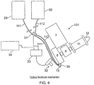
- Figure 4 depicts a real-time feedback system using an optical measuring device 32, and also shows further features of the print head 101 for delivery of accelerator and / or cartilage material.
- the feedback system comprises an optical sensor 32, a measurement processor 33 and an interface 34 with the main controller 110 of the robotic arm assembly 1.
- the optical sensor may comprise one or more cameras for viewing the layers of material being built up by extrusion from either one of the deposition heads 6 and 11.
- the optical sensor 32 (or plural sensors) may be static or mounted to a part of the robotic arm assembly 1 or may be mounted to the print head 101. Alternatively, the optical sensor or sensors 32 could be mounted to a separately moveable or indexable structure, e.g. on a separate track or a robotic arm.
- the optical sensor 32 e.g. camera, is preferably configured to capture information relating to texture, shape or form of the material deposited by either or both of the deposition heads 6, 11.
- the feedback system may measure some or all of the continuity, width, height and reflectance of the extruded bead (e.g. of cementitious material or other material to be described later) during deposition as well as any vertical, horizontal or other deformation of previously built layers.
- the feedback system may also monitor information relating to the surface finish and texture and three-dimensional location of the extruded bead and / or previously built layers with reference to the instructions generated from the computer model. Such information is processed in real-time in the measurement processor 33, and any variations to the set parameters may instigate changes to the deposition process, pump speed, velocity of travel by controlling the robot interface 34 and system pause, etc.
- Variations to the set parameters may be made “on the fly” as the material is deposited such that there is real-time feedback to the delivery apparatus to control current parameters being used to deposit the current layer being deposited. Alternatively, variations to the set parameters may be made to control future parameters, e.g. for the next deposited layer so as to "correct” or “repair” deviations from the intended profile of a previous layer or layers. Variations to the set parameters may include any of the operational parameters of the deposition apparatus such as to the pumps or nozzles or robotic arm assembly to control flow rates, height or position of the material being deposited.
- the print head 101 or delivery mechanism may further include a container 29 for an accelerator ("accelerating agent") and a container 30 for cartilage material.
- accelerating agent an accelerator
- container 30 for cartilage material Each of these containers 29, 30 is coupled to a nozzle 35 by way of delivery pipes 111, 112 and a solenoid valve 31 which is under the control of the measurement processor 33.
- the nozzle 35 may be integrated with the cementitious material nozzle 13 in the form of a multi-chamber nozzle. Alternatively, the nozzle 35 could be adjacent to, or concentric with, the cementitious material nozzle 13, e.g. forming a shroud.
- the accelerating agent and / or cartilage material may therefore be delivered through a nozzle 35 that is one or more of coaxial with, adjacent to, or at least partially surrounding the cementitious material nozzle 13.
- the accelerating agent nozzle and / or cartilage material nozzle 35 may comprise a circumferential shroud around the cementitious material nozzle 13 or may be incorporated within the cementitious material nozzle 13. This enables the cartilage material to be conveniently built up in layers simultaneously with, or interspersed with, the cementitious material, or as a base layer, intermediate layer or cap layer to the or each cementitious layer.
- Exemplary cartilage materials can include latex, gelatin, vinyl, metals (e.g. for electrical conductivity, finish or structural enhancement), expanding foam (e.g. for thermal insulation), resins, powders, textiles, dyes, inks and other surface finishes, or property-enhancing materials.
- the solenoid valve 31 controls the delivery of accelerator and cartilage material from the containers 29, 30 to be deposited through the nozzle 35.
- the systems of figure 4 for delivery of accelerator and cartilage material are shown as gravity fed systems. However, it is possible also to replace either of these with a pumped system. For example, a peristaltic pump could meter delivery of either or both accelerator or cartilage material to the nozzle 13.
- the container 29, valve 31, delivery pipe 111 and nozzle 35 or 13 provides an exemplary means for applying an accelerating agent to the stabilised cementitious material
- the main controller 110, interface 34 exemplify apparatus to control the flow rate of the timing and rate of application of an accelerating agent.
- An accelerator for the build (cementitious) material may comprise sulphuric, aluminium salt and diethanolamine, and can be selected to control the setting time of the cementitious material.
- the accelerator may be mixed with a retarder, e.g. formed by amino-tris (methylenephosphonic acid), citric and formaldehyde, to secure a sufficient open time to ensure layer buildability.
- a retarder e.g. formed by amino-tris (methylenephosphonic acid), citric and formaldehyde
- some retarder is premixed with the cementitious material provided in the hopper 102 and delivered to the deposition head 6. This provides a greater open time for use of the cementitious build material.
- accelerator is added later than the retarder, e.g. at the nozzle 13 to shorten the stiffening time after deposition of the material.
- Accelerator and cartilage materials in the containers 29, 30 of Figure 4 may be held under low pressure in the containers 29 and 30.
- solenoid valve 31 When solenoid valve 31 is energized in such a manner as to allow passage of material from either container 29 or 30 into the nozzle 35, deposition onto the previously laid surface is coated with material from the selected container 29, 30.
- the nozzle 35 may comprise a shroud which may consist of separated segments within, and may be rotatable to orientate in the direction of travel of the deposition head 6 along a work piece being constructed.
- the print head 101 in combination with the containers 29, 30, solenoid valve 31, delivery pipes 111, 112 and nozzle 13, 35 provide a reservoir for accelerating agent, a reservoir for cartilage material and means for delivering the accelerating agent and cartilage material to a nozzle for extrusion therefrom.
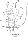
- FIG. 5 shows further detail of the deposition head 11 for support material.
- the support material is a sand-based material.
- Exemplary support material could be binder and sand.
- the binder is stored in a binder container 36 coupled to a mixing chamber 115 by a binder pump 37 and a binder entry point 38 of the mixing chamber 115.
- the support material (e.g. casting sand) is deliverable through a sand entry point 39 from a suitable container, not shown.
- the mixing chamber 115 includes mixing paddles 41, 42 for mixing the sand and binder.
- the paddles 41, 42 are rotated by a suitable motor 46 and shaft 117, which also rotates an anti-lodging rod 66 within the nozzle 12.
- Plates 43A, 43B have apertures 43.
- the mixed sand and binder is passed through the apertures 43 in the plates 43A, 43B which are size adjustable to regulate the rate at which the mixed material falls through, to control the mixing time in the mixing chamber 115 in order to maintain the degree of mixing.
- the mixed material is then extruded through the nozzle 12.
- the amount of support material in the mixing chamber 115 is controlled by a metering unit 40 comprising a rotating cylinder 118 with slits 119, and flow-rate of the support material is measured and controlled by a variable reluctance pickup 47 and a pump speed control circuit 48.
- the variable reluctance pickup creates a variable frequency signal according to the speed of rotation.
- variable reluctance pickup could alternatively be generated by other devices, such as Hall-effect or optical devices, for example.
- This variable frequency signal is fed to a frequency-to-voltage converter and then to a pulse width modulation (PWM) circuit to drive the binder pump 37.
- PWM pulse width modulation
- the binder pump is preferably driven so as to maintain a desired or constant sand binder ratio.
- the rotation of anti-lodging rod 66 prevents residues building up inside the nozzle 12.
- the mixing chamber 115 provides an exemplary reservoir for support material for delivery to the nozzle 12 and the main controller 110 further controls the rate of flow of the support material to the nozzle by way of the motor 46 and binder pump 37.
- an accelerator or "activation agent” for the support material may be delivered by way of an accelerator delivery pipe 44 to the nozzle 12.
- the nozzle 12 may be a multi-port nozzle and may include a shroud nozzle arrangement 45 to deliver the activation agent for the support material.
- the activation agent may therefore be delivered through a nozzle 45 that is one or more of coaxial with, adjacent to, or at least partially surrounding the support material nozzle 12.
- the activation agent nozzle 45 may comprise a circumferential slot around the support material nozzle 12. Another arrangement might be that the activation agent is mixed into the support material within the support material nozzle 12.
- Such arrangements as described above are ideally suited for dispensing casting sand or another suitable sand-based material that is set with a gaseous material, such as CO 2 .
- Moist sand e.g. generated by the deposition head 11 mixing sand from entry point 39 with a wet binder material (e.g. water) from binder container 36
- a wet binder material e.g. water
- binder container 36 e.g. water
- support materials may be used which can be removed and possibly recycled after deposition, e.g. after construction of an article, or after deposition of subsequent layers of cementitious material.
- a sand-based support material can be flushed with water during a later stage of the process.
- An exemplary activation agent for the support material may be carbon dioxide (CO 2 ), applied under low pressure to the mixed support material which accelerates the reaction between silica sand and sodium silicate, by causing desiccation.
- the accelerator may be delivered from an external cylinder (not shown), equipped with 6 mm pipe 44, and passed through a solenoid valve (not shown) to the exit nozzle 12 via the shroud 45.
- the support material can be activated during deposition.
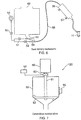
- FIG. 6 shows further details of a mechanism for delivery of the sand component of the support material.
- the support material e.g. dry silica sand
- the support material is blown through a delivery tube 55 from a bulk container 49 using low pressure compressed air, which is added through the air gauge 58 and needle valve 50, into a small reservoir 56 mounted near to the extreme end of the robotic arm assembly 1.
- Exhaust air from the reservoir 56 is regulated by the needle valve 52 and air tube 54 to reduce the velocity of dry sand to the deposition head 11 for the support material.
- a weight sensor 57 fitted to the reservoir 56 stops the flow of sand, using the needle valve 51 and air tube 53, when the reservoir 56 is full.
- Any one or more of the bulk container 49, the binder container 36 and the mixing chamber 115 may also exemplify a reservoir of support material.
- FIG 7 depicts the details of a stirrer arrangement 120 that allows continuous or periodic agitation of the cementitious material.
- the stirrer arrangement 120 may be disposed at any suitable location in the cementitious material delivery path, e.g. at the hopper 102 and worm pump 2 assembly shown in figure 1 or downstream thereof.
- the cementitious material is delivered to container 59 which includes a mixing or stirring paddle 62 and a vibrator 65.
- the mixing or stirring paddle 62 is rotatable by motor 60 by way of a shaft 61. Agitation of the material in the container 59 is performed by the motor 60 driving the shaft 61 and mixing paddle 62, and by the vibrator 65 shaking the container 59.
- the paddle 62 has a specific surface area, thus it requires a certain force to move it.
- the force which indicates the stiffness of the material, can be measured by a torque measuring unit 63.
- a force measurement processor 64 monitors the torque required to rotate the paddle 62 and adjusts process parameters and frequency and amplitude of the vibrator 65 to assist the flow of cementitious material.
- the stirring paddle 62 and / or the vibrator 65 exemplify agitation means suitable for agitating cementitious material or stabilised cementitious material.
- FIG 8 shows a vibrating nozzle arrangement 121 configured to compact material as it is being deposited and improve inter-layer bonding for wet materials as well as improving surface finish.
- the vibrating nozzle arrangement 121 can be deployed either for depositing build (cementitious) material or support material, i.e. it can be incorporated into the nozzle 13 or the nozzle 12 of figures 2 and 3a .
- FIG. 8 shows the vibrating nozzle arrangement 121 serving as a cementitious material nozzle.
- Cementitious material may be delivered through the hose 18 or other conduit, e.g. via the roller pump 24.
- the hose 18 is retained in a nozzle head 122 and is vibrated vertically (as orientated in the diagram) by the vibrator 123, i.e. the vibration occurs in the direction parallel to the hose long axis and in the direction of extrusion.
- the vibrator 123 may be a piezo-electric stack connected to a power supply through wires 67.
- a voice coil or mechanical movement could also or alternatively be employed for larger amplitudes while the vibrator 123 remains fixed.
- the application of ultrasonic vibration to the deposition head nozzle could also or alternatively be used for smaller amplitudes for precise material control.
- figure 8 provides a vibratable nozzle.
- the vibratable nozzle could be configured to vibrate the nozzle in a direction parallel to the nozzle axis.
- the nozzle axis in this context, corresponds to the longitudinal axis of the hose and the direction of extrusion.
- a vibrating nozzle may improve the flow of material being extruded through the nozzle and or compact the extruded materials.
- the vibratable nozzle could be configured to vibrate the nozzle in a direction orthogonal to the nozzle axis. This may result in a different quality of surface without surface compaction.
- Figures 9a and 9b show a variable diameter nozzle 130 configured to provide variable bead dimensions and variable bead aspect ratio. This allows higher density of fill for certain geometries and provides fast dynamic system response.
- variable diameter nozzle 130 can be deployed either for depositing build (cementitious) material or support material, i.e. it can be incorporated into the nozzle 13 or the nozzle 12 of figures 2 and 3a .
- FIG. 9a and 9b shows the variable diameter nozzle 130 serving as a cementitious material nozzle 13.
- Cementitious material may be delivered through the hose 18 or other conduit, e.g. via the roller pump 24.
- the hose 18 is coupled into a hose housing 132 in nozzle 130 and the hose has multiple axial slots 131 cut to maximise closing movement.
- the axial slots 131 are preferably also slightly oblique to the long axis of the hose and preferably also somewhat oblique to the radial direction of the hose.
- a motor and gearbox 68 are coupled to rotate a pinion gear 69, which engages and turns a ring gear 70 that is attached to a closing block 71.
- a thread 73 couples the ring gear 70 and closing block 71.
- Complementary tapered profiles 75 on each of the ring closing block 71 and hose housing 132 causes compression of the distal end 72 of the hose housing 132 when the closing block and nozzle 13 are axially displaced relative to one another using the thread 73. This causes the end of the hose housing 132 and hose 18 to reduce or increase in radius, thereby defining a variable diameter nozzle 130.
- variable diameter nozzle is intended to encompass a nozzle in which at least one cross-sectional dimension of a nozzle end can be varied.
- the cross-sectional profile need not be circular or elliptical, but could be rectangular, or other multi-sided shape.
- the hose need not have slots in it but could rely on pliancy, plasticity or elasticity of the hose material to contract or expand.
- a variable diameter nozzle whose orifice can be automatically adjusted in shape and / or size to change the cross-sectional profile of extruded material in a controlled and continuous manner can be particularly useful when a layer of material to be deposited requires the formation of one or more beads which are required to be smaller or narrower than the standard bead size for a printed layer of material. This may avoid the need to leave partial gaps or change nozzles when different resolutions of printed bead are required.
- the main controller 110 may be used to control any function of the delivery apparatus 100 based on information / feedback received from the optical sensor 32, such as flow rate of material to the nozzles 12, 13, 35, 45 and extrusion rate therefrom.
- the optical sensor or sensors could be replaced by or supplemented with other types of sensor suitable for monitoring the texture, shape or form of the layers being printed by the apparatus 100. For example, sensors using other parts of the electromagnetic spectrum or ultrasound could be used.
- a gantry system which presents an x-y-z stage for the print head 101.
- the gantry system may comprise four columns with two supporting beams that track vertically.
- the two supporting beams in turn support a third beam that tracks along one horizontal axis that supports the print head.
- the print head can then track in the other horizontal direction along the third beam.
- Other arrangements are, of course, possible.
- the main controller 110 is preferably a computer control means although application specific circuits could be deployed instead or in addition.
- the main controller can be a single central unit or could be distributed among the various component parts of the apparatus 100.
- cementitious deposition head nozzle 13 and the support material deposition head nozzle 12 of the preferred embodiments have been shown as having different angular presentations on the print head 101 ( figure 2 ) so that they can each be rotated into position ( figures 2a and 2b ) for deposition on a surface 104, it will be understood that the cementitious material nozzle 13 and the support material nozzle 12 could alternatively be provided in the same orientation, and could be immediately adjacent one another, so as to provide for simultaneous deposition or more rapid switching between deposition of cementitious material and support material, for example.
- Advantages of enabling the delivery of both cementitious material and support material in a "printing" type process is that a reduced, or minimum, volume and mass of cementitious material can be delivered to the point of use, reducing the cost and time for building and post-processing, clear-up and recycling time.
- the delivery paths for both cementitious material and the support material can be separately optimised for delivery to and from the same print head. This enables formation of structures that include hollow panels and components and doubly curved structures.
- the deposition process can be combined with other surface preparation or surface treatment techniques, e.g. for forming smooth surfaces, such as tamping, or by a vibration / oscillatory instrument, air jets or combinations thereof.
Landscapes
- Engineering & Computer Science (AREA)
- Chemical & Material Sciences (AREA)
- Mechanical Engineering (AREA)
- Manufacturing & Machinery (AREA)
- Ceramic Engineering (AREA)
- Materials Engineering (AREA)
- Automation & Control Theory (AREA)
- Optics & Photonics (AREA)
- Physics & Mathematics (AREA)
- Coating Apparatus (AREA)
- Producing Shaped Articles From Materials (AREA)
- Devices For Post-Treatments, Processing, Supply, Discharge, And Other Processes (AREA)
- Curing Cements, Concrete, And Artificial Stone (AREA)
- On-Site Construction Work That Accompanies The Preparation And Application Of Concrete (AREA)
- Preparation Of Clay, And Manufacture Of Mixtures Containing Clay Or Cement (AREA)
- Application Of Or Painting With Fluid Materials (AREA)
- Manipulator (AREA)
Claims (23)
- Procédé de construction multicouche dans lequel la construction de chaque couche comprend les étapes suivantes :utilisation d'un matériau cimentaire ;acheminement dudit matériau cimentaire jusqu'à une tuyère (13) indexation de ladite tuyère le long d'une voie prédéfinie ; etapplication dudit matériau cimentaire à une surface de travail par extrusion à travers ladite tuyère ;ces étapes se répétant pour chaque couche supplémentaire de construction requise le procédé comprenant en outre :
sensiblement simultanément avec ladite application dudit matériau cimentaire, l'application d'un matériau de soutien dans une couche contiguë avec ledit matériau cimentaire dans des zones où le matériau cimentaire n'est pas souhaité, de sorte que ledit matériau de soutien, ainsi que ledit matériau cimentaire, procurent la surface de travail pour la couche suivante de construction, caractérisé par le fait que le matériau de soutien est un matériau sableux. - Procédé de construction selon la revendication 1, dans lequel le matériau de soutien contient du sable siliceux et du silicate de sodium.
- Procédé de construction selon la revendication 1, dans lequel le matériau cimentaire est un matériau cimentaire stabilisé ou un matériau de type béton.
- Procédé de construction selon l'une quelconque des revendications 1, 2 ou 3, comprenant en outre l'étape d'application d'un agent d'accélération dans ledit matériau cimentaire.
- Procédé de construction selon la revendication 1, comprenant en outre l'exposition dudit matériau de soutien à un agent d'activation.
- Procédé de construction selon la revendication 5, dans lequel l'agent d'activation est une substance gazeuse.
- Procédé de construction selon la revendication 5, dans lequel l'agent d'activation est du dioxyde de carbone.
- Procédé de construction selon l'une des revendications 1 ou 5, comprenant en outre l'application d'une couche de cartilage à la surface supérieure de la couche de soutien dans des zones où la couche suivante doit être cimentaire, ou vice versa.
- Procédé de construction selon l'une quelconque des revendications précédentes, comprenant en outre l'emploi d'au moins une caméra (32) pour capturer des informations en temps réel liées à la texture de surface et/ou la déformation de la surface de travail, lesdites informations servant à déterminer l'application des conditions nécessaire pour l'application de couche en cours.
- Procédé de construction selon la revendication 9, dans lequel lesdites conditions d'application sont au moins la taille de tuyère, l'orientation de tuyère, le débit du matériau cimentaire, la vitesse d'indexation de tuyère et le taux ou le minutage de l'application d'agent d'accélération.
- Appareil (100) permettant d'effectuer un procédé de construction multicouche conforme à l'une quelconque des revendications précédentes, comprenant un réservoir (4) de matériau cimentaire, ledit réservoir étant relié fonctionnellement à une tuyère (13) de matériau cimentaire, un moyen (1) permettant d'indexer ladite tuyère de matériau cimentaire le long d'une voie prédéfinie, un moyen (5) permettant de réguler l'écoulement dudit matériau cimentaire dudit réservoir à ladite tuyère (13) de matériau cimentaire et l'extrusion dudit matériau hors de ladite tuyère, l'appareil comprenant en outre :
un réservoir (49, 56, 36, 115) de matériau de soutien, ledit réservoir étant relié fonctionnellement à une tuyère (12) d'application de matériau de soutien, un moyen (1) permettant d'indexer ladite tuyère d'application de matériau de soutien le long d'une voie prédéfinie, des moyens (37, 46, 110, 115) permettant de réguler l'écoulement dudit matériau de soutien dudit réservoir (49, 36, 115) à ladite tuyère (12) d'application de matériau de soutien et d'extruder ledit matériau hors de ladite tuyère d'application de matériau de soutien, caractérisé en ce que le réservoir de matériau de soutien comprend un matériau sableux. - Appareil selon la revendication 11, dans lequel le réservoir de matériau de soutien contient un sable siliceux et du silicate de sodium.
- Appareil selon la revendication 11, comprenant en outre un récipient de liaison (36) de matériau de liaison couplé à une chambre de mélange (115), la chambre de mélange étant également couplée au réservoir (49) de matériau de soutien et comprenant des pales de mélange (41, 42) permettant de mélanger le sable et le liant avant l'extrusion à travers la tuyère (12) d'application de matériau de soutien.
- Appareil selon la revendication 11, comprenant en outre des moyens (13, 29, 31, 35, 111) permettant d'appliquer un agent d'accélération dans ledit matériau cimentaire.
- Appareil selon la revendication 11, comprenant en outre des moyens d'agitation (62, 65), lesdits moyens d'agitation étant en communication fonctionnelle avec ledit réservoir et/ou en connexion fonctionnelle entre ledit réservoir et ladite tuyère.
- Appareil selon la revendication 11, comprenant en outre des moyens (44, 45) permettant d'appliquer un agent d'activation sur ledit matériau de soutien.
- Appareil selon la revendication 16, dans lequel le moyen permettant d'appliquer un agent d'activation sur ledit matériau de soutien contient une source de substance gazeuse d'activation et un moyen (44) permettant d'acheminer ladite substance gazeuse d'activation jusqu'à ladite tuyère (12) d'application de matériau de soutien.
- Appareil selon la revendication 17, dans lequel la source de substance gazeuse d'activation comprend une source de dioxyde de carbone.
- Appareil selon la revendication 17, dans lequel la tuyère (12) d'application de matériau de soutien comprend un flasque (45) permettant d'appliquer la substance gazeuse d'activation au matériau de soutien extrudé à travers la tuyère d'application de matériau de soutien.
- Appareil selon l'une quelconque des revendications 11 à 19, comprenant en outre un réservoir (30) de matériau cartilagineux, ledit réservoir étant relié fonctionnellement à une tuyère (35) d'application de matériau cartilagineux, un moyen d'indexation de ladite tuyère le long d'une voie prédéfinie, un moyen de régulation de l'écoulement dudit matériau cartilagineux dudit réservoir à ladite tuyère et l'extrusion dudit matériau hors de ladite tuyère.
- Appareil selon l'une quelconque des revendications précédentes, comprenant en outre au moins une caméra (32), lesdites au moins une caméra étant soit statique, montée à un bras de robot ou indépendamment indexable pour suivre lesdites au moins une tuyère, lesdites caméras étant à même de capturer des informations relatives à la texture ou à la forme, ladite au moins une caméra étant à même de transférer lesdites informations vers une unité de commande informatique (110), ladite unité de commande informatique étant à même d'interpréter lesdites informations puis d'utiliser lesdites informations pour informer la commande de ladite au moins une tuyère et l'écoulement desdits au moins un matériau dudit au moins un réservoir auxdites au moins une tuyère.
- Appareil selon l'une quelconque des revendications 11 à 21, dans lequel l'une quelconque des tuyères comprend une tuyère pouvant vibrer (121).
- Appareil selon l'une quelconque des revendications 11 à 21, dans lequel l'une quelconque des tuyères comprend une tuyère à diamètre variable (130).
Applications Claiming Priority (3)
| Application Number | Priority Date | Filing Date | Title |
|---|---|---|---|
| GBGB1118807.5A GB201118807D0 (en) | 2011-11-01 | 2011-11-01 | Method and apparatus |
| PCT/GB2012/052717 WO2013064826A1 (fr) | 2011-11-01 | 2012-10-31 | Procédé et appareil pour l'écoulement de liant hydraulique |
| EP12795587.0A EP2773492B1 (fr) | 2011-11-01 | 2012-10-31 | Procédé et appareil pour la distribution d'un matériau à base de ciment |
Related Parent Applications (2)
| Application Number | Title | Priority Date | Filing Date |
|---|---|---|---|
| EP12795587.0A Division-Into EP2773492B1 (fr) | 2011-11-01 | 2012-10-31 | Procédé et appareil pour la distribution d'un matériau à base de ciment |
| EP12795587.0A Division EP2773492B1 (fr) | 2011-11-01 | 2012-10-31 | Procédé et appareil pour la distribution d'un matériau à base de ciment |
Publications (2)
| Publication Number | Publication Date |
|---|---|
| EP2886277A1 EP2886277A1 (fr) | 2015-06-24 |
| EP2886277B1 true EP2886277B1 (fr) | 2018-12-12 |
Family
ID=45375612
Family Applications (2)
| Application Number | Title | Priority Date | Filing Date |
|---|---|---|---|
| EP15150702.7A Not-in-force EP2886277B1 (fr) | 2011-11-01 | 2012-10-31 | Procédé et appareil pour la distribution d'un matériau cimentaire |
| EP12795587.0A Not-in-force EP2773492B1 (fr) | 2011-11-01 | 2012-10-31 | Procédé et appareil pour la distribution d'un matériau à base de ciment |
Family Applications After (1)
| Application Number | Title | Priority Date | Filing Date |
|---|---|---|---|
| EP12795587.0A Not-in-force EP2773492B1 (fr) | 2011-11-01 | 2012-10-31 | Procédé et appareil pour la distribution d'un matériau à base de ciment |
Country Status (8)
| Country | Link |
|---|---|
| US (1) | US20140252668A1 (fr) |
| EP (2) | EP2886277B1 (fr) |
| JP (2) | JP6058685B2 (fr) |
| CN (2) | CN106363770A (fr) |
| AU (1) | AU2012330948A1 (fr) |
| EA (1) | EA201400523A1 (fr) |
| GB (1) | GB201118807D0 (fr) |
| WO (1) | WO2013064826A1 (fr) |
Cited By (5)
| Publication number | Priority date | Publication date | Assignee | Title |
|---|---|---|---|---|
| DE102021121046A1 (de) | 2021-08-12 | 2023-02-16 | Wilhelm Tölke GmbH & Co KG | Vorrichtung und Verfahren zur Herstellung von Bauwerken oder Objekten aus eingefärbtem Beton |
| DE102021133597A1 (de) | 2021-12-17 | 2023-06-22 | AEDITIVE GmbH | Verfahren und Herstellungssystem zur automatisierten Herstellung eines dünnwandigen Betonbauteils mit einem Spritzbetonverfahren und Schalungswerkzeug |
| DE102023116955A1 (de) * | 2023-06-27 | 2025-01-02 | Putzmeister Engineering Gmbh | Extrudervorrichtung, Extrudersystem und Verwendung |
| DE102023116954A1 (de) * | 2023-06-27 | 2025-01-02 | Putzmeister Engineering Gmbh | Verfahren und Fördersystem |
| US12611818B2 (en) | 2024-07-05 | 2026-04-28 | ARC Ventures LLC | Mechanism to control the density gradient in three-dimensionally printed material |
Families Citing this family (159)
| Publication number | Priority date | Publication date | Assignee | Title |
|---|---|---|---|---|
| GB201118807D0 (en) * | 2011-11-01 | 2011-12-14 | Univ Loughborough | Method and apparatus |
| WO2014121917A1 (fr) * | 2013-02-08 | 2014-08-14 | Eth Zurich | Appareil et procédé de formage de structures de béton par coffrage glissant |
| US9724877B2 (en) | 2013-06-23 | 2017-08-08 | Robert A. Flitsch | Methods and apparatus for mobile additive manufacturing of advanced structures and roadways |
| US20150021832A1 (en) * | 2013-07-18 | 2015-01-22 | Mitsubishi Electric Research Laboratories, Inc. | Method and Apparatus for Additively Manufacturing of Objects Based on Tensile Strength |
| US9481131B2 (en) * | 2013-07-18 | 2016-11-01 | Mitsubishi Electric Research Laboratories, Inc. | Method and apparatus for printing 3D objects using additive manufacturing and material extruder with translational and rotational axes |
| JP2015030211A (ja) * | 2013-08-04 | 2015-02-16 | 泰 金田 | 自然な方向にそって印刷する3次元印刷方法および3dプリンタ |
| GB201314030D0 (en) * | 2013-08-06 | 2013-09-18 | Eads Uk Ltd | Extrusion-Based Additive Manufacturing System and Method |
| DE102013216855B4 (de) * | 2013-08-23 | 2022-10-20 | Mühlbauer Technology Gmbh | Vorrichtung und Verfahren zur Herstellung von Formkörpern |
| US11077607B2 (en) | 2013-10-21 | 2021-08-03 | Made In Space, Inc. | Manufacturing in microgravity and varying external force environments |
| US10725451B2 (en) | 2013-10-21 | 2020-07-28 | Made In Space, Inc. | Terrestrial and space-based manufacturing systems |
| US10730232B2 (en) * | 2013-11-19 | 2020-08-04 | Guill Tool & Engineering Co, Inc. | Coextruded, multilayer and multicomponent 3D printing inputs |
| CN103600407A (zh) * | 2013-11-21 | 2014-02-26 | 福建海源三维打印高科技有限公司 | 一种三维打印机 |
| WO2015127247A2 (fr) * | 2014-02-21 | 2015-08-27 | Israel Noah | Construction d'impression par pulvérisation |
| WO2015127555A1 (fr) * | 2014-02-26 | 2015-09-03 | Freespace Composites Inc. | Système de fabrication utilisant un logiciel de conception par optimisation topologique, des mécanismes d'impression en trois dimensions et des matériaux composites structurels |
| JP6030185B2 (ja) * | 2014-05-14 | 2016-11-24 | ソク−ムン,キム | 3dプリンティング装置及び方法、これを利用した鉄骨コンクリート構造物の施工方法 |
| WO2015176141A1 (fr) * | 2014-05-23 | 2015-11-26 | Mineraltec Pty Ltd | Système et procédé relatifs à des déchets recyclés |
| SG10201505877SA (en) * | 2014-07-28 | 2016-02-26 | Beyon 3D Ltd | Method and system for fabrication of custom-made molds and concrete - architectural components |
| JP6428049B2 (ja) * | 2014-08-25 | 2018-11-28 | 富士ゼロックス株式会社 | 積層造形装置及び積層造形プログラム |
| EP3238916B1 (fr) * | 2014-09-21 | 2019-07-10 | Made In Space, Inc. | Systèmes de fabrication terrestre et dans l'espace |
| CN107073814B (zh) * | 2014-10-03 | 2020-01-14 | X开发有限责任公司 | 持续拉动三维打印 |
| US9873223B2 (en) * | 2014-10-05 | 2018-01-23 | X Development Llc | Shifting a curing location during 3D printing |
| DE102014224176A1 (de) | 2014-11-26 | 2016-06-02 | Weeke Bohrsysteme Gmbh | Vorrichtung zur Ausbildung von Volumenkörpern |
| JP2016108801A (ja) * | 2014-12-05 | 2016-06-20 | 前田建設工業株式会社 | 3dプリンターを用いた複合構造物の構築装置 |
| CN104878935B (zh) | 2015-04-17 | 2017-10-10 | 张彭成 | 一种可以控制凝结时间的混凝土施工方法及其专用设备 |
| KR102321632B1 (ko) * | 2015-04-24 | 2021-11-05 | (주) 디아이 | 3d 프린터를 이용한 엘이디 조명 히트싱크 제조방법 |
| US10780637B2 (en) * | 2015-06-10 | 2020-09-22 | Apis Cor Engineering, Llc | 3-D printer in polar coordinates |
| MX383522B (es) | 2015-06-11 | 2025-03-13 | Effusiontech IP Pty Ltd | Aparato y método para formar objetos tridimensionales. |
| DE202015009607U1 (de) | 2015-08-14 | 2018-07-30 | Franka Emika Gmbh | Robotersystem und Gehäuseteil für ein solches Robotersystem |
| US9702144B2 (en) | 2015-09-03 | 2017-07-11 | Caterpillar Inc. | Extruded walls and method of forming extruded walls |
| DE102015217143A1 (de) * | 2015-09-08 | 2017-03-09 | Siemens Aktiengesellschaft | Durchführung, Düse und 3D-Drucker |
| EP3147269A1 (fr) * | 2015-09-22 | 2017-03-29 | HeidelbergCement AG | Impression 3d des elements et batiments en ciment bct |
| JP6563755B2 (ja) * | 2015-09-24 | 2019-08-21 | 太平洋セメント株式会社 | セメント質硬化体の強度増進方法 |
| DE102015012962B4 (de) * | 2015-10-08 | 2024-08-22 | Franka Emika Gmbh | Robotersystem |
| CN105216333B (zh) * | 2015-11-16 | 2020-03-24 | 陈志敏 | 一种三维打印机流体挤出系统及其实现方法 |
| WO2017090032A1 (fr) * | 2015-11-24 | 2017-06-01 | Pinhas Gilboa | Tête d'impression pour imprimantes 3d |
| US20170173884A1 (en) * | 2015-12-22 | 2017-06-22 | Western Digital Technologies, Inc. | Rotation and nozzle opening control of extruders in printing systems |
| US10611073B2 (en) | 2015-12-28 | 2020-04-07 | Thermwood Corporation | Machine and method for forming articles |
| FR3047258A1 (fr) * | 2016-01-28 | 2017-08-04 | Pierre-Emmanuel Drochon | Fabrication de pre-murs courbes par fabrication additive (impression 3d) a triple extrusion |
| WO2017136702A1 (fr) * | 2016-02-04 | 2017-08-10 | Provisur Technologies, Inc. | Plaque de remplissage |
| WO2017149040A1 (fr) * | 2016-03-01 | 2017-09-08 | Sika Technology Ag | Mélangeur, système pour appliquer un matériau de construction et procédé pour fabriquer une structure en matériau de construction |
| JP7017672B2 (ja) * | 2016-04-01 | 2022-02-09 | 株式会社Hpc沖縄 | 繊維製セル構造コンクリートの製造方法 |
| JP2017185645A (ja) * | 2016-04-01 | 2017-10-12 | 太平洋セメント株式会社 | セメント質混練物の造形用付加製造システム |
| US10074449B2 (en) * | 2016-06-21 | 2018-09-11 | Raytheon Company | Additively manufactured concrete-bearing radiation attenuation structure |
| EP3260258B1 (fr) | 2016-06-22 | 2019-06-26 | Holcim Technology Ltd. | Commande en ligne de la rhéologie d'un matériau de construction pour impression 3d |
| CN106003419B (zh) * | 2016-07-14 | 2018-07-17 | 周仕谊 | 一种基于混联结构的道路沿边砌筑智能机器人用混料机 |
| US9993964B2 (en) | 2016-07-14 | 2018-06-12 | Xerox Corporation | Method and system for producing three-dimensional build objects |
| CN106320713B (zh) * | 2016-10-11 | 2019-12-06 | 博湃建筑科技(上海)有限公司 | 3d建筑打印作业平台 |
| US10717207B2 (en) * | 2016-10-24 | 2020-07-21 | Gregory D. Vialle | 3D printer |
| US10953598B2 (en) * | 2016-11-04 | 2021-03-23 | Continuous Composites Inc. | Additive manufacturing system having vibrating nozzle |
| US10870234B2 (en) | 2016-11-08 | 2020-12-22 | Purdue Research Foundation | Methods and apparatus for 3d printing of highly viscous materials |
| JP6792430B2 (ja) * | 2016-11-28 | 2020-11-25 | 前田建設工業株式会社 | 3dプリント技術を用いた建設構造物の構築装置 |
| JP6831678B2 (ja) * | 2016-11-29 | 2021-02-17 | 川崎重工業株式会社 | ロボット及びその運転方法、並びに塗布システム |
| CN106827168B (zh) * | 2016-12-07 | 2019-05-17 | 南京工业大学 | 一种混凝土3d打印工艺 |
| IT201600128438A1 (it) * | 2016-12-20 | 2018-06-20 | Gimac Di Maccagnan Giorgio | Sistema per processi di additive manufacturing e relativo metodo di controllo |
| EP3558679B1 (fr) * | 2016-12-21 | 2021-04-28 | Sika Technology AG | Fabrication additive de corps moulés en matériaux durcissables |
| CN106639318A (zh) * | 2017-01-06 | 2017-05-10 | 马义军 | 一种用于建筑3d打印的智能伺服联动送料系统 |
| US10414066B2 (en) * | 2017-01-16 | 2019-09-17 | Jing Zhang | Slurry dispense system |
| JP7149687B2 (ja) * | 2017-02-02 | 2022-10-07 | 太平洋セメント株式会社 | 付加製造方法 |
| EP3366450A1 (fr) * | 2017-02-23 | 2018-08-29 | Siemens Aktiengesellschaft | Fabrication additive avec transport pneumatique de produit en vrac en utilisant surpression |
| CN106830843B (zh) * | 2017-03-05 | 2019-08-09 | 北京工业大学 | 一种适用于3d打印快速成型工艺的水泥基复合材料 |
| US10870239B2 (en) | 2017-03-08 | 2020-12-22 | John Fenley | Three-dimensional printing systems and methods |
| CN108625598A (zh) * | 2017-03-24 | 2018-10-09 | 盈创建筑科技(上海)有限公司 | 一种3d建筑打印机的机架结构 |
| CN106907006B (zh) * | 2017-04-13 | 2022-11-25 | 博湃建筑科技(上海)有限公司 | 建筑轮廓成型机 |
| CN107009482B (zh) * | 2017-05-08 | 2022-05-17 | 龙泉市金宏瓷业有限公司 | 陶瓷打印机挤出装置和陶瓷泥料在线改性打印方法 |
| JP2018199939A (ja) * | 2017-05-26 | 2018-12-20 | 大成建設株式会社 | 複合構造物の施工方法、複合構造物および複合構造物施工装置 |
| FR3067637B1 (fr) * | 2017-06-14 | 2020-08-14 | Xtreee | Systeme d'extrusion de cordons de materiau cimentaire pour robot de fabrication additive de structures architecturales |
| US10800085B2 (en) | 2017-06-28 | 2020-10-13 | The Boeing Company | Apparatuses for shaping an extrudable material |
| US10836108B1 (en) | 2017-06-30 | 2020-11-17 | Made In Space, Inc. | System and method for monitoring and inspection of feedstock material for direct feedback into a deposition process |
| US11426927B2 (en) | 2017-07-31 | 2022-08-30 | Hewlett-Packard Development Company, L.P. | Different mixtures of build materials deliverable during a three dimensional print operation |
| US11559919B2 (en) | 2017-08-09 | 2023-01-24 | Sika Technology Ag | Method for the application of mineral binder compositions containing fibres |
| WO2019030329A1 (fr) | 2017-08-09 | 2019-02-14 | Sika Technology Ag | Système d'application d'un matériau de construction |
| PT4086056T (pt) | 2017-08-09 | 2024-06-05 | Sika Tech Ag | Metodo para produzir uma estrutura a partir de um material de construção |
| CN110997260A (zh) | 2017-08-09 | 2020-04-10 | Sika技术股份公司 | 用于矿物粘合剂成分3d打印的方法 |
| ES2945764T3 (es) * | 2017-08-09 | 2023-07-06 | Sika Tech Ag | Sistema para la aplicación de un material de construcción |
| FR3070302B1 (fr) * | 2017-08-24 | 2019-08-30 | Xtreee | Systeme d'extrusion de cordons de materiau de construction pour robot de fabrication additive de structures architecturales comprenant un dispositif d'insertion de fibres de renforcement |
| CN113500775B (zh) | 2017-08-24 | 2023-12-26 | 精工爱普生株式会社 | 造型材料供给装置、三维造型装置 |
| US10870219B2 (en) * | 2017-10-11 | 2020-12-22 | Caterpillar Inc. | Monitoring system for three-dimensional printing |
| CN107553710B (zh) * | 2017-10-17 | 2024-03-29 | 河北工业大学 | 一种水泥基材料3d打印分级存储输送机构 |
| CN107605161A (zh) * | 2017-10-25 | 2018-01-19 | 马义军 | 一种全地形建筑3d打印机 |
| US10759114B2 (en) * | 2017-12-29 | 2020-09-01 | Continuous Composites Inc. | System and print head for continuously manufacturing composite structure |
| CN108318381B (zh) * | 2018-01-04 | 2020-04-28 | 河北工业大学 | 一种水泥基材料3d可打印性能的优化方法 |
| CN108454089B (zh) * | 2018-02-08 | 2021-07-23 | 义乌市亚威机械设备有限公司 | 一种便于复合塑料生产的塑料制品生产台 |
| CN108748983B (zh) * | 2018-04-28 | 2019-08-20 | 中国矿业大学 | 一种地下封存空间构建封存系统 |
| CN108724695B (zh) * | 2018-04-28 | 2019-10-08 | 中国矿业大学 | 一种地下封存空间的构建封存方法 |
| SI25656A (sl) * | 2018-06-01 | 2019-12-31 | Jože Abram | Mešalno brizgalna glava za tridimenzionalni tiskalnik za tiskanje sten zgradb in metoda tiskanja |
| EP3575054A1 (fr) | 2018-06-01 | 2019-12-04 | Fundacíon Tecnalia Research & Innovation | Appareil et procédé pour l'impression en 3d d'objets ou de structures en matériau cimentaire |
| CN108897585B (zh) * | 2018-06-29 | 2019-11-05 | 北京华航唯实机器人科技股份有限公司 | 机器人的后置处理程序的配置方法及设备 |
| DE102018116795B4 (de) * | 2018-07-11 | 2020-06-04 | Kurt Seume Spezialmaschinenbau Gmbh | Vorrichtung zur Herstellung von Werkstücken |
| CN112955417A (zh) | 2018-08-29 | 2021-06-11 | Gcp应用技术有限公司 | 水泥质组合物中的未水化强度 |
| PL427212A1 (pl) * | 2018-09-27 | 2020-04-06 | Rebuild Spółka Z Ograniczoną Odpowiedzialnością | Urządzenie do i sposób tworzenia podpór, szalunków lub struktur z tworzyw spienionych oraz urządzenie do i sposób tworzenia budowli |
| DE102018217141A1 (de) * | 2018-10-08 | 2020-04-09 | B.T. Innovation Gmbh | Druckkopf zum Drucken dreidimensionaler Strukturen aus Beton und Verfahren dazu |
| US11260589B2 (en) * | 2018-10-18 | 2022-03-01 | Sidus Space, Inc. | Print head for regolith-polymer mixture and associated feedstock |
| CN109779260B (zh) * | 2018-10-22 | 2023-12-05 | 北京美斯顿科技开发有限公司 | 一种机器人智慧3d建筑打印机 |
| FR3088569B1 (fr) * | 2018-11-15 | 2020-10-16 | Xtreee | Systeme d'extrusion de cordons de materiau de construction pour robot de fabrication additive de structures architecturales comprenant un dispositif de fluidification du materiau cimentaire extrude |
| JP7159814B2 (ja) | 2018-11-28 | 2022-10-25 | セイコーエプソン株式会社 | 三次元造形装置、および、三次元造形物の製造方法 |
| CN109366999B (zh) * | 2018-12-20 | 2020-07-28 | 大连学庆铭锋数控技术有限公司 | 一种物料搅拌和挤出同时进行的3d打印喷头装置 |
| US10399247B1 (en) * | 2018-12-27 | 2019-09-03 | Qatar University | Compound nozzle for cement 3D printer to produce thermally insulated composite cement |
| JP7229024B2 (ja) * | 2019-01-24 | 2023-02-27 | Ube三菱セメント株式会社 | セメントスラリーの吐出装置 |
| EP3708321A1 (fr) | 2019-03-15 | 2020-09-16 | Sika Technology Ag | Système d'application d'un matériau de construction |
| EP4316760A3 (fr) | 2019-03-15 | 2024-03-20 | Sika Technology AG | Système d'application d'un matériel de construction |
| DE102019204230A1 (de) * | 2019-03-27 | 2020-10-01 | Putzmeister Engineering Gmbh | Verfahren zur Herstellung von einem Bauwerksteil, System zur Herstellung von einem Bauwerksteil und Bauwerksteil |
| DE102019204244A1 (de) * | 2019-03-27 | 2020-10-01 | Putzmeister Engineering Gmbh | Druckverfahren und Drucksystem |
| DE102019204228A1 (de) * | 2019-03-27 | 2020-10-01 | Putzmeister Engineering Gmbh | Extrudervorrichtung, Extrudersystem und Verwendung einer Extrudervorrichtung und/oder eines Extrudersystems |
| DE102019107833A1 (de) * | 2019-03-27 | 2020-10-01 | Putzmeister Engineering Gmbh | Vorrichtung für das Ausbringen eines fluiden Prozesswerkstoffs |
| FR3097152B1 (fr) * | 2019-06-14 | 2023-10-20 | Ecole Nat Des Ponts Et Chaussees | Procédé et dispositif de fabrication d’un béton fibré anisotrope |
| JP7287150B2 (ja) | 2019-06-28 | 2023-06-06 | セイコーエプソン株式会社 | 三次元造形装置および三次元造形物の製造方法 |
| WO2021014300A1 (fr) * | 2019-07-19 | 2021-01-28 | Tvasta Manufacturing Solutions Private Limited | Ensemble pompe pour système d'impression tridimensionnelle |
| US11554535B2 (en) * | 2019-08-03 | 2023-01-17 | Maurizio Ramia | Variable nozzle extrusion system for 3D printing |
| RU2724163C1 (ru) | 2019-08-28 | 2020-06-22 | Общество с ограниченной ответственностью «АМТ» | Экструдер строительных смесей для 3d принтера |
| JP7373961B2 (ja) * | 2019-09-30 | 2023-11-06 | 株式会社北川鉄工所 | 補強コンクリート柱の製造装置および製造方法 |
| JP7336340B2 (ja) * | 2019-09-30 | 2023-08-31 | 株式会社北川鉄工所 | 補強コンクリート柱の製造装置 |
| JP7492329B2 (ja) * | 2019-11-29 | 2024-05-29 | 太平洋セメント株式会社 | 付加製造装置用水硬性組成物の硬化体の反りの修正方法 |
| US11236517B2 (en) | 2019-12-23 | 2022-02-01 | Saudi Arabian Oil Company | Cementitious print head, 3D printing architecture, and cementitious printing methodology |
| DE102020110431A1 (de) | 2020-04-16 | 2021-10-21 | AEDITIVE GmbH | Fertigungssystem zur generativen Herstellung von Bauteilen und Verfahren |
| RU2020115021A (ru) * | 2020-04-28 | 2021-10-28 | Общество с ограниченной ответственностью «АМТ» | Прямоточный экструдер для строительных смесей |
| EP4149762A4 (fr) * | 2020-05-18 | 2024-04-24 | Gannett Peak Partners LLC | Plateforme robotique pour construction |
| JP7450219B2 (ja) * | 2020-06-22 | 2024-03-15 | 学校法人金沢工業大学 | 施工方法、製作方法、情報処理装置 |
| JP7528559B2 (ja) | 2020-06-26 | 2024-08-06 | セイコーエプソン株式会社 | 三次元造形装置 |
| LU101897B1 (en) * | 2020-06-27 | 2022-01-10 | BigRep GmbH | 3D-printing system and method |
| US12528226B2 (en) | 2020-07-03 | 2026-01-20 | The Regents Of The University Of Michigan | Additive manufacturing of engineered cementitious composites |
| JP7516953B2 (ja) | 2020-07-28 | 2024-07-17 | セイコーエプソン株式会社 | 三次元造形装置および三次元造形物の製造方法 |
| DE102020121301A1 (de) * | 2020-08-13 | 2022-02-17 | AEDITIVE GmbH | Düsenvorrichtung zum Herstellen eines dreidimensionalen Bauteils und Verfahren |
| CN112140529A (zh) * | 2020-08-17 | 2020-12-29 | 东华大学 | 一种回转类曲面结构复合材料增材制造装置 |
| CN112067668A (zh) * | 2020-08-28 | 2020-12-11 | 深圳大学 | 一种实时监测3d打印胶凝复合材料硬化过程的装置 |
| CN112171847A (zh) * | 2020-09-10 | 2021-01-05 | 华中科技大学 | 一种超声辅助3d打印混凝土喷嘴装置及挤出系统 |
| EP4005760A1 (fr) * | 2020-11-25 | 2022-06-01 | Saint-Gobain Weber France | Procédé d'impression 3d pour la fabrication d'éléments à base de mortier |
| CN112743826A (zh) * | 2020-12-21 | 2021-05-04 | 安徽理工大学 | 一种矿山相似模拟3d打印实验系统 |
| JP7600674B2 (ja) | 2020-12-24 | 2024-12-17 | セイコーエプソン株式会社 | 三次元造形装置、および三次元造形物の製造方法 |
| DE102021200694B4 (de) * | 2021-01-27 | 2023-12-07 | Festo Se & Co. Kg | Bearbeitungssystem zur Werkstückbearbeitung |
| JP7597618B2 (ja) * | 2021-03-10 | 2024-12-10 | 清水建設株式会社 | 水中における構造物の施工方法 |
| US12377575B2 (en) * | 2021-03-26 | 2025-08-05 | James Lyman Reusch | Lightweight apparatus for large scale additive manufacturing with cementitious materials |
| US12390955B2 (en) * | 2021-03-26 | 2025-08-19 | James Lyman Reusch | Apparatus for additive manufacturing including a batch mixer for cementitious materials |
| WO2022204602A1 (fr) * | 2021-03-26 | 2022-09-29 | Reusch James Lyman | Appareil de fabrication additive comprenant un mélangeur discontinu pour matériaux cimentaires |
| JP7641814B2 (ja) * | 2021-05-12 | 2025-03-07 | 大成建設株式会社 | コンクリート締固め方法、コンクリート締固め装置およびコンクリート締固め装置用針アタッチメント |
| FR3126333B1 (fr) * | 2021-08-25 | 2024-01-19 | Saint Gobain Weber France | contrôle d’impression 3D |
| US12330332B2 (en) * | 2021-11-09 | 2025-06-17 | Arelac, Inc. | Methods and systems for 3D printing of reactive vaterite cement |
| CN114102797B (zh) * | 2021-12-27 | 2023-01-31 | 中交第一公路勘察设计研究院有限公司 | 一种3d打印建筑材料可打印性能的量化装置及其使用方法 |
| US12479125B2 (en) | 2022-02-15 | 2025-11-25 | Titan America LLC | Concrete composition suitable for 3-D printing and a method for 3-D printing of multiple layers of concrete |
| HUE073115T2 (hu) * | 2022-02-17 | 2025-12-28 | Cosmos 3D Innovatech Int S L | 3D nyomtatást és additív gyártást alkalmazó intelligens építõrendszer és eljárás |
| JP2023136832A (ja) * | 2022-03-17 | 2023-09-29 | 太平洋セメント株式会社 | 造形物の造形方法 |
| JP7370026B1 (ja) * | 2022-05-20 | 2023-10-27 | スターテクノ株式会社 | 三次元造形装置 |
| JP7458041B1 (ja) * | 2022-05-20 | 2024-03-29 | スターテクノ株式会社 | 流体物吐出装置及びその流体物吐出装置を備えた三次元造形装置 |
| US20230399259A1 (en) * | 2022-06-09 | 2023-12-14 | Pike Scientific Industries LLC | Construction methods using synthetic polymer binders |
| JP2023183678A (ja) * | 2022-06-16 | 2023-12-28 | 大成建設株式会社 | 立体造形システム |
| CN115319750B (zh) * | 2022-08-31 | 2024-08-20 | 北京华航唯实机器人科技股份有限公司 | 机器人的后置处理程序的配置方法及装置 |
| WO2024064272A2 (fr) * | 2022-09-21 | 2024-03-28 | Board Of Regents For The Oklahoma Agricultural And Mechanical Colleges | Procédés et système d'impression de béton 3d |
| FR3140571B1 (fr) * | 2022-10-10 | 2024-10-25 | Xtreee | Système d’extrusion de materiau de construction equipé d’un dispositif de mesure de la largeur des cordons extrudés |
| US12264490B2 (en) | 2022-11-16 | 2025-04-01 | Ge Infrastructure Technology Llc | System and method for manufacturing a tower structure |
| CN115723222A (zh) * | 2022-11-18 | 2023-03-03 | 河北量子智能科技有限公司 | 一种基于混凝土3d打印的电控系统 |
| WO2024112785A1 (fr) * | 2022-11-21 | 2024-05-30 | The Regents Of The University Of Michigan | Pulvérisation additive automatisée à buses multiples et procédés de pulvérisation additive pour former du béton renforcé de fibres |
| CN116442348B (zh) * | 2023-03-08 | 2025-10-14 | 中国长江三峡集团有限公司 | 一种3d打印施工装置及施工方法 |
| FR3148931B1 (fr) * | 2023-05-25 | 2025-08-15 | Xtreee | Système d’extrusion de materiau de construction equipé d’un dispositif d’injection d’un retardateur de prise en tete d’impression |
| CN116619440A (zh) * | 2023-06-02 | 2023-08-22 | 袁烽 | 六轴机械臂的控制方法、设备及可读存储介质 |
| FR3149822B1 (fr) * | 2023-06-13 | 2025-06-06 | Saint Gobain Weber France | Tête d’impression 3D avec obturateur |
| IT202300015690A1 (it) * | 2023-07-26 | 2025-01-26 | Stone Expert Srl | Macchina per la colata di una resina |
| CN117416041B (zh) * | 2023-10-20 | 2024-12-10 | 太原理工大学 | 一种多模式3d打印机头及应用其的协同打印方法 |
| WO2025189107A1 (fr) * | 2024-03-08 | 2025-09-12 | The Regents Of The University Of Michigan | Impression tridimensionnelle en béton (3dcp) de pièces à topologie optimisée : parcours d'outil à information géométrique et dépôt de matière variable |
| WO2025199192A1 (fr) * | 2024-03-20 | 2025-09-25 | The Trustees Of The University Of Pennsylvania | Béton imprimable en 3d, léger, à haute résistance, pour le captage du carbone et le stockage du carbone |
| FR3161587A1 (fr) * | 2024-04-30 | 2025-10-31 | Saint Gobain Weber France | Procédé de surfaçage d’une surface d’un objet imprimé en 3 dimensions |
Family Cites Families (22)
| Publication number | Priority date | Publication date | Assignee | Title |
|---|---|---|---|---|
| JPS5637887Y2 (fr) * | 1979-07-27 | 1981-09-04 | ||
| AT385550B (de) * | 1985-06-20 | 1988-04-11 | Ruzicka Klaus Dipl Ing Dr Tech | Einrichtung zur herstellung von bauteilen od. gebaeuden mittels rechengesteuerten produktionsmaschinen |
| JPH0796216B2 (ja) * | 1988-10-24 | 1995-10-18 | 株式会社竹中工務店 | Pc版製造用型枠の製造方法 |
| US5121329A (en) * | 1989-10-30 | 1992-06-09 | Stratasys, Inc. | Apparatus and method for creating three-dimensional objects |
| JP2597778B2 (ja) * | 1991-01-03 | 1997-04-09 | ストラタシイス,インコーポレイテッド | 三次元対象物組み立てシステム及び組み立て方法 |
| FI912206A7 (fi) * | 1991-05-07 | 1992-11-08 | Lohja Parma Eng Lpe Oy | Betonin valusuutin ja menetelmä betonin valamiseksi |
| JPH0780824A (ja) * | 1993-09-14 | 1995-03-28 | Sekisui Chem Co Ltd | モルタル供給装置 |
| DE69633143T2 (de) * | 1995-11-09 | 2005-08-04 | Toyota Jidosha K.K., Toyota | Verfahren und Vorrichtung zur Herstellung einer 3-D Sandform mit Kern durch Ausbildung von Sandschichten |
| JP4038698B2 (ja) * | 1995-11-30 | 2008-01-30 | 株式会社藤木工務店 | 曲面プレキャスト板の製造方法 |
| JPH1072271A (ja) * | 1996-08-30 | 1998-03-17 | Mitsubishi Materials Corp | セメント成形雛型の製造方法 |
| JPH10235623A (ja) * | 1997-02-21 | 1998-09-08 | Ohbayashi Corp | セメント系材料を用いた立体成形方法 |
| JPH11300729A (ja) * | 1998-04-24 | 1999-11-02 | Kayaba Ind Co Ltd | 打設方法とその装置 |
| JP2001047520A (ja) * | 1999-08-04 | 2001-02-20 | Toyota Motor Corp | 積層造形方法 |
| US7153454B2 (en) * | 2003-01-21 | 2006-12-26 | University Of Southern California | Multi-nozzle assembly for extrusion of wall |
| US7874825B2 (en) * | 2005-10-26 | 2011-01-25 | University Of Southern California | Nozzle for forming an extruded wall with rib-like interior |
| EP1711328B1 (fr) * | 2004-01-20 | 2013-03-13 | University of Southern California | Systeme robotique pour la construction automatisee |
| US7680555B2 (en) * | 2006-04-03 | 2010-03-16 | Stratasys, Inc. | Auto tip calibration in an extrusion apparatus |
| JP2008098280A (ja) * | 2006-10-10 | 2008-04-24 | Shinano Kenshi Co Ltd | 電子部品立体成形装置 |
| US8568121B2 (en) * | 2007-11-27 | 2013-10-29 | University Of Southern California | Techniques for sensing material flow rate in automated extrusion |
| US8245757B2 (en) * | 2009-02-02 | 2012-08-21 | Stratasys, Inc. | Inorganic ionic support materials for digital manufacturing systems |
| CN201685313U (zh) * | 2010-06-09 | 2010-12-29 | 柳玉元 | 可生产多种形状墙板的推挤式成型机 |
| GB201118807D0 (en) * | 2011-11-01 | 2011-12-14 | Univ Loughborough | Method and apparatus |
-
2011
- 2011-11-01 GB GBGB1118807.5A patent/GB201118807D0/en not_active Ceased
-
2012
- 2012-10-31 JP JP2014539402A patent/JP6058685B2/ja not_active Expired - Fee Related
- 2012-10-31 US US14/355,560 patent/US20140252668A1/en not_active Abandoned
- 2012-10-31 AU AU2012330948A patent/AU2012330948A1/en not_active Abandoned
- 2012-10-31 CN CN201610817450.9A patent/CN106363770A/zh active Pending
- 2012-10-31 EP EP15150702.7A patent/EP2886277B1/fr not_active Not-in-force
- 2012-10-31 EA EA201400523A patent/EA201400523A1/ru unknown
- 2012-10-31 EP EP12795587.0A patent/EP2773492B1/fr not_active Not-in-force
- 2012-10-31 WO PCT/GB2012/052717 patent/WO2013064826A1/fr not_active Ceased
- 2012-10-31 CN CN201280054134.0A patent/CN104023925A/zh active Pending
-
2016
- 2016-12-07 JP JP2016237361A patent/JP2017052289A/ja active Pending
Non-Patent Citations (1)
| Title |
|---|
| None * |
Cited By (6)
| Publication number | Priority date | Publication date | Assignee | Title |
|---|---|---|---|---|
| DE102021121046A1 (de) | 2021-08-12 | 2023-02-16 | Wilhelm Tölke GmbH & Co KG | Vorrichtung und Verfahren zur Herstellung von Bauwerken oder Objekten aus eingefärbtem Beton |
| DE102021133597A1 (de) | 2021-12-17 | 2023-06-22 | AEDITIVE GmbH | Verfahren und Herstellungssystem zur automatisierten Herstellung eines dünnwandigen Betonbauteils mit einem Spritzbetonverfahren und Schalungswerkzeug |
| WO2023110000A1 (fr) | 2021-12-17 | 2023-06-22 | AEDITIVE GmbH | Procédé et système de production pour la production automatisée d'un élément en béton à paroi mince au moyen d'un procédé de pulvérisation de béton et d'un moule de coffrage |
| DE102023116955A1 (de) * | 2023-06-27 | 2025-01-02 | Putzmeister Engineering Gmbh | Extrudervorrichtung, Extrudersystem und Verwendung |
| DE102023116954A1 (de) * | 2023-06-27 | 2025-01-02 | Putzmeister Engineering Gmbh | Verfahren und Fördersystem |
| US12611818B2 (en) | 2024-07-05 | 2026-04-28 | ARC Ventures LLC | Mechanism to control the density gradient in three-dimensionally printed material |
Also Published As
| Publication number | Publication date |
|---|---|
| WO2013064826A1 (fr) | 2013-05-10 |
| JP2017052289A (ja) | 2017-03-16 |
| CN106363770A (zh) | 2017-02-01 |
| EP2773492B1 (fr) | 2017-06-28 |
| JP6058685B2 (ja) | 2017-01-11 |
| EP2773492A1 (fr) | 2014-09-10 |
| US20140252668A1 (en) | 2014-09-11 |
| EA201400523A1 (ru) | 2014-08-29 |
| EP2886277A1 (fr) | 2015-06-24 |
| AU2012330948A1 (en) | 2014-05-15 |
| CN104023925A (zh) | 2014-09-03 |
| JP2015502870A (ja) | 2015-01-29 |
| GB201118807D0 (en) | 2011-12-14 |
Similar Documents
| Publication | Publication Date | Title |
|---|---|---|
| EP2886277B1 (fr) | Procédé et appareil pour la distribution d'un matériau cimentaire | |
| JP6030185B2 (ja) | 3dプリンティング装置及び方法、これを利用した鉄骨コンクリート構造物の施工方法 | |
| JP7117692B2 (ja) | 3dプリンタ用ノズル装置および3dプリンタ装置並びにこれを用いた建造物の構築方法、粘性材料の供給方法および製作物構築装置 | |
| CN108025498B (zh) | 一种涂覆流体的方法和设备 | |
| CN205735414U (zh) | 计算机控制的系统和混凝土喷射装置 | |
| US20170232679A1 (en) | Apparatus for Fabricating an Object | |
| US6036777A (en) | Powder dispensing apparatus using vibration | |
| CN110919001B (zh) | 成型材料共混送进式铝基复合材料3d打印装置及打印方法 | |
| US10414093B2 (en) | Three-dimensional molding device and three-dimensional molding method | |
| JP7386474B2 (ja) | 立体造形システム | |
| KR20180087486A (ko) | 건축용 3d 프린터 | |
| CN106113509B (zh) | 多向超声微滴喷射光固化增材制造装置及方法 | |
| CN103561923B (zh) | 制造具有至少一种连续的特性改变的构件的装置和方法 | |
| RU2724163C1 (ru) | Экструдер строительных смесей для 3d принтера | |
| Lachmayer et al. | Automated shotcrete 3D printing-Printing interruption for extended component complexity | |
| CN106273509A (zh) | 振动成型的材料挤压式3d打印机 | |
| US20190322043A1 (en) | Method for operating a multi-nozzle extruder using zig-zag patterns that provide improved structual integrity | |
| US20230030198A1 (en) | Fast layered extrusion for additive manufacturing | |
| US20230031850A1 (en) | Fast layered extrusion for additive manufacturing | |
| CN109371971B (zh) | 用于桩基础3d打印混凝土的喷头装置及使用方法 | |
| CN206186375U (zh) | 振动成型的材料挤压式3d打印机 | |
| CN110528884B (zh) | 一种适用于小型混凝土构件的3d打印装置及方法、应用 | |
| JP7759607B2 (ja) | 立体造形システム | |
| JP7697626B2 (ja) | 立体造形システムおよび立体造形方法 | |
| CN119748861A (zh) | 一种多喷头挤出与喷射一体式三维打印装置及使用方法 |
Legal Events
| Date | Code | Title | Description |
|---|---|---|---|
| PUAI | Public reference made under article 153(3) epc to a published international application that has entered the european phase |
Free format text: ORIGINAL CODE: 0009012 |
|
| 17P | Request for examination filed |
Effective date: 20150109 |
|
| AC | Divisional application: reference to earlier application |
Ref document number: 2773492 Country of ref document: EP Kind code of ref document: P |
|
| AK | Designated contracting states |
Kind code of ref document: A1 Designated state(s): AL AT BE BG CH CY CZ DE DK EE ES FI FR GB GR HR HU IE IS IT LI LT LU LV MC MK MT NL NO PL PT RO RS SE SI SK SM TR |
|
| R17P | Request for examination filed (corrected) |
Effective date: 20151218 |
|
| RBV | Designated contracting states (corrected) |
Designated state(s): AL AT BE BG CH CY CZ DE DK EE ES FI FR GB GR HR HU IE IS IT LI LT LU LV MC MK MT NL NO PL PT RO RS SE SI SK SM TR |
|
| STAA | Information on the status of an ep patent application or granted ep patent |
Free format text: STATUS: EXAMINATION IS IN PROGRESS |
|
| 17Q | First examination report despatched |
Effective date: 20170201 |
|
| REG | Reference to a national code |
Ref country code: DE Ref legal event code: R079 Ref document number: 602012054735 Country of ref document: DE Free format text: PREVIOUS MAIN CLASS: B28B0003200000 Ipc: B28B0001000000 |
|
| GRAP | Despatch of communication of intention to grant a patent |
Free format text: ORIGINAL CODE: EPIDOSNIGR1 |
|
| STAA | Information on the status of an ep patent application or granted ep patent |
Free format text: STATUS: GRANT OF PATENT IS INTENDED |
|
| RIC1 | Information provided on ipc code assigned before grant |
Ipc: B28B 3/20 20060101ALI20180125BHEP Ipc: B28B 17/00 20060101ALI20180125BHEP Ipc: B28B 1/00 20060101AFI20180125BHEP Ipc: B28B 3/26 20060101ALI20180125BHEP |
|
| INTG | Intention to grant announced |
Effective date: 20180213 |
|
| GRAJ | Information related to disapproval of communication of intention to grant by the applicant or resumption of examination proceedings by the epo deleted |
Free format text: ORIGINAL CODE: EPIDOSDIGR1 |
|
| STAA | Information on the status of an ep patent application or granted ep patent |
Free format text: STATUS: EXAMINATION IS IN PROGRESS |
|
| GRAP | Despatch of communication of intention to grant a patent |
Free format text: ORIGINAL CODE: EPIDOSNIGR1 |
|
| STAA | Information on the status of an ep patent application or granted ep patent |
Free format text: STATUS: GRANT OF PATENT IS INTENDED |
|
| INTC | Intention to grant announced (deleted) | ||
| RAP1 | Party data changed (applicant data changed or rights of an application transferred) |
Owner name: LOUGHBOROUGH UNIVERSITY Owner name: CONCRENETICS |
|
| INTG | Intention to grant announced |
Effective date: 20180626 |
|
| GRAS | Grant fee paid |
Free format text: ORIGINAL CODE: EPIDOSNIGR3 |
|
| GRAA | (expected) grant |
Free format text: ORIGINAL CODE: 0009210 |
|
| STAA | Information on the status of an ep patent application or granted ep patent |
Free format text: STATUS: THE PATENT HAS BEEN GRANTED |
|
| AC | Divisional application: reference to earlier application |
Ref document number: 2773492 Country of ref document: EP Kind code of ref document: P |
|
| AK | Designated contracting states |
Kind code of ref document: B1 Designated state(s): AL AT BE BG CH CY CZ DE DK EE ES FI FR GB GR HR HU IE IS IT LI LT LU LV MC MK MT NL NO PL PT RO RS SE SI SK SM TR |
|
| REG | Reference to a national code |
Ref country code: GB Ref legal event code: FG4D |
|
| REG | Reference to a national code |
Ref country code: CH Ref legal event code: EP |
|
| REG | Reference to a national code |
Ref country code: AT Ref legal event code: REF Ref document number: 1075341 Country of ref document: AT Kind code of ref document: T Effective date: 20181215 |
|
| REG | Reference to a national code |
Ref country code: DE Ref legal event code: R096 Ref document number: 602012054735 Country of ref document: DE |
|
| REG | Reference to a national code |
Ref country code: IE Ref legal event code: FG4D |
|
| REG | Reference to a national code |
Ref country code: NL Ref legal event code: FP |
|
| REG | Reference to a national code |
Ref country code: LT Ref legal event code: MG4D |
|
| PG25 | Lapsed in a contracting state [announced via postgrant information from national office to epo] |
Ref country code: HR Free format text: LAPSE BECAUSE OF FAILURE TO SUBMIT A TRANSLATION OF THE DESCRIPTION OR TO PAY THE FEE WITHIN THE PRESCRIBED TIME-LIMIT Effective date: 20181212 Ref country code: BG Free format text: LAPSE BECAUSE OF FAILURE TO SUBMIT A TRANSLATION OF THE DESCRIPTION OR TO PAY THE FEE WITHIN THE PRESCRIBED TIME-LIMIT Effective date: 20190312 Ref country code: FI Free format text: LAPSE BECAUSE OF FAILURE TO SUBMIT A TRANSLATION OF THE DESCRIPTION OR TO PAY THE FEE WITHIN THE PRESCRIBED TIME-LIMIT Effective date: 20181212 Ref country code: LV Free format text: LAPSE BECAUSE OF FAILURE TO SUBMIT A TRANSLATION OF THE DESCRIPTION OR TO PAY THE FEE WITHIN THE PRESCRIBED TIME-LIMIT Effective date: 20181212 Ref country code: ES Free format text: LAPSE BECAUSE OF FAILURE TO SUBMIT A TRANSLATION OF THE DESCRIPTION OR TO PAY THE FEE WITHIN THE PRESCRIBED TIME-LIMIT Effective date: 20181212 Ref country code: LT Free format text: LAPSE BECAUSE OF FAILURE TO SUBMIT A TRANSLATION OF THE DESCRIPTION OR TO PAY THE FEE WITHIN THE PRESCRIBED TIME-LIMIT Effective date: 20181212 Ref country code: NO Free format text: LAPSE BECAUSE OF FAILURE TO SUBMIT A TRANSLATION OF THE DESCRIPTION OR TO PAY THE FEE WITHIN THE PRESCRIBED TIME-LIMIT Effective date: 20190312 |
|
| REG | Reference to a national code |
Ref country code: AT Ref legal event code: MK05 Ref document number: 1075341 Country of ref document: AT Kind code of ref document: T Effective date: 20181212 |
|
| PG25 | Lapsed in a contracting state [announced via postgrant information from national office to epo] |
Ref country code: GR Free format text: LAPSE BECAUSE OF FAILURE TO SUBMIT A TRANSLATION OF THE DESCRIPTION OR TO PAY THE FEE WITHIN THE PRESCRIBED TIME-LIMIT Effective date: 20190313 Ref country code: RS Free format text: LAPSE BECAUSE OF FAILURE TO SUBMIT A TRANSLATION OF THE DESCRIPTION OR TO PAY THE FEE WITHIN THE PRESCRIBED TIME-LIMIT Effective date: 20181212 Ref country code: AL Free format text: LAPSE BECAUSE OF FAILURE TO SUBMIT A TRANSLATION OF THE DESCRIPTION OR TO PAY THE FEE WITHIN THE PRESCRIBED TIME-LIMIT Effective date: 20181212 Ref country code: SE Free format text: LAPSE BECAUSE OF FAILURE TO SUBMIT A TRANSLATION OF THE DESCRIPTION OR TO PAY THE FEE WITHIN THE PRESCRIBED TIME-LIMIT Effective date: 20181212 |
|
| PG25 | Lapsed in a contracting state [announced via postgrant information from national office to epo] |
Ref country code: PL Free format text: LAPSE BECAUSE OF FAILURE TO SUBMIT A TRANSLATION OF THE DESCRIPTION OR TO PAY THE FEE WITHIN THE PRESCRIBED TIME-LIMIT Effective date: 20181212 Ref country code: PT Free format text: LAPSE BECAUSE OF FAILURE TO SUBMIT A TRANSLATION OF THE DESCRIPTION OR TO PAY THE FEE WITHIN THE PRESCRIBED TIME-LIMIT Effective date: 20190412 Ref country code: CZ Free format text: LAPSE BECAUSE OF FAILURE TO SUBMIT A TRANSLATION OF THE DESCRIPTION OR TO PAY THE FEE WITHIN THE PRESCRIBED TIME-LIMIT Effective date: 20181212 Ref country code: IT Free format text: LAPSE BECAUSE OF FAILURE TO SUBMIT A TRANSLATION OF THE DESCRIPTION OR TO PAY THE FEE WITHIN THE PRESCRIBED TIME-LIMIT Effective date: 20181212 |
|
| PG25 | Lapsed in a contracting state [announced via postgrant information from national office to epo] |
Ref country code: SK Free format text: LAPSE BECAUSE OF FAILURE TO SUBMIT A TRANSLATION OF THE DESCRIPTION OR TO PAY THE FEE WITHIN THE PRESCRIBED TIME-LIMIT Effective date: 20181212 Ref country code: EE Free format text: LAPSE BECAUSE OF FAILURE TO SUBMIT A TRANSLATION OF THE DESCRIPTION OR TO PAY THE FEE WITHIN THE PRESCRIBED TIME-LIMIT Effective date: 20181212 Ref country code: SM Free format text: LAPSE BECAUSE OF FAILURE TO SUBMIT A TRANSLATION OF THE DESCRIPTION OR TO PAY THE FEE WITHIN THE PRESCRIBED TIME-LIMIT Effective date: 20181212 Ref country code: IS Free format text: LAPSE BECAUSE OF FAILURE TO SUBMIT A TRANSLATION OF THE DESCRIPTION OR TO PAY THE FEE WITHIN THE PRESCRIBED TIME-LIMIT Effective date: 20190412 Ref country code: RO Free format text: LAPSE BECAUSE OF FAILURE TO SUBMIT A TRANSLATION OF THE DESCRIPTION OR TO PAY THE FEE WITHIN THE PRESCRIBED TIME-LIMIT Effective date: 20181212 |
|
| REG | Reference to a national code |
Ref country code: DE Ref legal event code: R097 Ref document number: 602012054735 Country of ref document: DE |
|
| PLBE | No opposition filed within time limit |
Free format text: ORIGINAL CODE: 0009261 |
|
| STAA | Information on the status of an ep patent application or granted ep patent |
Free format text: STATUS: NO OPPOSITION FILED WITHIN TIME LIMIT |
|
| PG25 | Lapsed in a contracting state [announced via postgrant information from national office to epo] |
Ref country code: SI Free format text: LAPSE BECAUSE OF FAILURE TO SUBMIT A TRANSLATION OF THE DESCRIPTION OR TO PAY THE FEE WITHIN THE PRESCRIBED TIME-LIMIT Effective date: 20181212 Ref country code: AT Free format text: LAPSE BECAUSE OF FAILURE TO SUBMIT A TRANSLATION OF THE DESCRIPTION OR TO PAY THE FEE WITHIN THE PRESCRIBED TIME-LIMIT Effective date: 20181212 Ref country code: DK Free format text: LAPSE BECAUSE OF FAILURE TO SUBMIT A TRANSLATION OF THE DESCRIPTION OR TO PAY THE FEE WITHIN THE PRESCRIBED TIME-LIMIT Effective date: 20181212 |
|
| 26N | No opposition filed |
Effective date: 20190913 |
|
| PG25 | Lapsed in a contracting state [announced via postgrant information from national office to epo] |
Ref country code: TR Free format text: LAPSE BECAUSE OF FAILURE TO SUBMIT A TRANSLATION OF THE DESCRIPTION OR TO PAY THE FEE WITHIN THE PRESCRIBED TIME-LIMIT Effective date: 20181212 |
|
| PG25 | Lapsed in a contracting state [announced via postgrant information from national office to epo] |
Ref country code: MC Free format text: LAPSE BECAUSE OF FAILURE TO SUBMIT A TRANSLATION OF THE DESCRIPTION OR TO PAY THE FEE WITHIN THE PRESCRIBED TIME-LIMIT Effective date: 20181212 |
|
| REG | Reference to a national code |
Ref country code: CH Ref legal event code: PL |
|
| PG25 | Lapsed in a contracting state [announced via postgrant information from national office to epo] |
Ref country code: LU Free format text: LAPSE BECAUSE OF NON-PAYMENT OF DUE FEES Effective date: 20191031 Ref country code: CH Free format text: LAPSE BECAUSE OF NON-PAYMENT OF DUE FEES Effective date: 20191031 Ref country code: LI Free format text: LAPSE BECAUSE OF NON-PAYMENT OF DUE FEES Effective date: 20191031 |
|
| PG25 | Lapsed in a contracting state [announced via postgrant information from national office to epo] |
Ref country code: IE Free format text: LAPSE BECAUSE OF NON-PAYMENT OF DUE FEES Effective date: 20191031 |
|
| PG25 | Lapsed in a contracting state [announced via postgrant information from national office to epo] |
Ref country code: CY Free format text: LAPSE BECAUSE OF FAILURE TO SUBMIT A TRANSLATION OF THE DESCRIPTION OR TO PAY THE FEE WITHIN THE PRESCRIBED TIME-LIMIT Effective date: 20181212 |
|
| PG25 | Lapsed in a contracting state [announced via postgrant information from national office to epo] |
Ref country code: MT Free format text: LAPSE BECAUSE OF FAILURE TO SUBMIT A TRANSLATION OF THE DESCRIPTION OR TO PAY THE FEE WITHIN THE PRESCRIBED TIME-LIMIT Effective date: 20181212 Ref country code: HU Free format text: LAPSE BECAUSE OF FAILURE TO SUBMIT A TRANSLATION OF THE DESCRIPTION OR TO PAY THE FEE WITHIN THE PRESCRIBED TIME-LIMIT; INVALID AB INITIO Effective date: 20121031 |
|
| PGFP | Annual fee paid to national office [announced via postgrant information from national office to epo] |
Ref country code: FR Payment date: 20210913 Year of fee payment: 10 Ref country code: NL Payment date: 20210928 Year of fee payment: 10 |
|
| PGFP | Annual fee paid to national office [announced via postgrant information from national office to epo] |
Ref country code: BE Payment date: 20210916 Year of fee payment: 10 |
|
| PGFP | Annual fee paid to national office [announced via postgrant information from national office to epo] |
Ref country code: DE Payment date: 20210923 Year of fee payment: 10 |
|
| PG25 | Lapsed in a contracting state [announced via postgrant information from national office to epo] |
Ref country code: MK Free format text: LAPSE BECAUSE OF FAILURE TO SUBMIT A TRANSLATION OF THE DESCRIPTION OR TO PAY THE FEE WITHIN THE PRESCRIBED TIME-LIMIT Effective date: 20181212 |
|
| PGFP | Annual fee paid to national office [announced via postgrant information from national office to epo] |
Ref country code: GB Payment date: 20221019 Year of fee payment: 11 |
|
| REG | Reference to a national code |
Ref country code: DE Ref legal event code: R119 Ref document number: 602012054735 Country of ref document: DE |
|
| REG | Reference to a national code |
Ref country code: NL Ref legal event code: MM Effective date: 20221101 |
|
| REG | Reference to a national code |
Ref country code: BE Ref legal event code: MM Effective date: 20221031 |
|
| PG25 | Lapsed in a contracting state [announced via postgrant information from national office to epo] |
Ref country code: NL Free format text: LAPSE BECAUSE OF NON-PAYMENT OF DUE FEES Effective date: 20221101 Ref country code: FR Free format text: LAPSE BECAUSE OF NON-PAYMENT OF DUE FEES Effective date: 20221031 Ref country code: DE Free format text: LAPSE BECAUSE OF NON-PAYMENT OF DUE FEES Effective date: 20230503 |
|
| PG25 | Lapsed in a contracting state [announced via postgrant information from national office to epo] |
Ref country code: BE Free format text: LAPSE BECAUSE OF NON-PAYMENT OF DUE FEES Effective date: 20221031 |
|
| GBPC | Gb: european patent ceased through non-payment of renewal fee |
Effective date: 20231031 |
|
| PG25 | Lapsed in a contracting state [announced via postgrant information from national office to epo] |
Ref country code: GB Free format text: LAPSE BECAUSE OF NON-PAYMENT OF DUE FEES Effective date: 20231031 |
|
| PG25 | Lapsed in a contracting state [announced via postgrant information from national office to epo] |
Ref country code: GB Free format text: LAPSE BECAUSE OF NON-PAYMENT OF DUE FEES Effective date: 20231031 |