EP2905121B1 - Dispositif et procédé de production de structures tridimensionnelles - Google Patents
Dispositif et procédé de production de structures tridimensionnelles Download PDFInfo
- Publication number
- EP2905121B1 EP2905121B1 EP15160153.1A EP15160153A EP2905121B1 EP 2905121 B1 EP2905121 B1 EP 2905121B1 EP 15160153 A EP15160153 A EP 15160153A EP 2905121 B1 EP2905121 B1 EP 2905121B1
- Authority
- EP
- European Patent Office
- Prior art keywords
- laser
- consolidated
- focusing optics
- carrier unit
- solidified
- Prior art date
- Legal status (The legal status is an assumption and is not a legal conclusion. Google has not performed a legal analysis and makes no representation as to the accuracy of the status listed.)
- Active
Links
Images


Classifications
-
- B—PERFORMING OPERATIONS; TRANSPORTING
- B29—WORKING OF PLASTICS; WORKING OF SUBSTANCES IN A PLASTIC STATE IN GENERAL
- B29C—SHAPING OR JOINING OF PLASTICS; SHAPING OF MATERIAL IN A PLASTIC STATE, NOT OTHERWISE PROVIDED FOR; AFTER-TREATMENT OF THE SHAPED PRODUCTS, e.g. REPAIRING
- B29C64/00—Additive manufacturing, i.e. manufacturing of three-dimensional [3D] objects by additive deposition, additive agglomeration or additive layering, e.g. by 3D printing, stereolithography or selective laser sintering
- B29C64/20—Apparatus for additive manufacturing; Details thereof or accessories therefor
- B29C64/264—Arrangements for irradiation
- B29C64/268—Arrangements for irradiation using laser beams; using electron beams [EB]
- B29C64/273—Arrangements for irradiation using laser beams; using electron beams [EB] pulsed; frequency modulated
-
- B—PERFORMING OPERATIONS; TRANSPORTING
- B29—WORKING OF PLASTICS; WORKING OF SUBSTANCES IN A PLASTIC STATE IN GENERAL
- B29C—SHAPING OR JOINING OF PLASTICS; SHAPING OF MATERIAL IN A PLASTIC STATE, NOT OTHERWISE PROVIDED FOR; AFTER-TREATMENT OF THE SHAPED PRODUCTS, e.g. REPAIRING
- B29C64/00—Additive manufacturing, i.e. manufacturing of three-dimensional [3D] objects by additive deposition, additive agglomeration or additive layering, e.g. by 3D printing, stereolithography or selective laser sintering
- B29C64/10—Processes of additive manufacturing
- B29C64/106—Processes of additive manufacturing using only liquids or viscous materials, e.g. depositing a continuous bead of viscous material
- B29C64/124—Processes of additive manufacturing using only liquids or viscous materials, e.g. depositing a continuous bead of viscous material using layers of liquid which are selectively solidified
- B29C64/129—Processes of additive manufacturing using only liquids or viscous materials, e.g. depositing a continuous bead of viscous material using layers of liquid which are selectively solidified characterised by the energy source therefor, e.g. by global irradiation combined with a mask
- B29C64/135—Processes of additive manufacturing using only liquids or viscous materials, e.g. depositing a continuous bead of viscous material using layers of liquid which are selectively solidified characterised by the energy source therefor, e.g. by global irradiation combined with a mask the energy source being concentrated, e.g. scanning lasers or focused light sources
-
- B—PERFORMING OPERATIONS; TRANSPORTING
- B29—WORKING OF PLASTICS; WORKING OF SUBSTANCES IN A PLASTIC STATE IN GENERAL
- B29C—SHAPING OR JOINING OF PLASTICS; SHAPING OF MATERIAL IN A PLASTIC STATE, NOT OTHERWISE PROVIDED FOR; AFTER-TREATMENT OF THE SHAPED PRODUCTS, e.g. REPAIRING
- B29C64/00—Additive manufacturing, i.e. manufacturing of three-dimensional [3D] objects by additive deposition, additive agglomeration or additive layering, e.g. by 3D printing, stereolithography or selective laser sintering
- B29C64/30—Auxiliary operations or equipment
- B29C64/386—Data acquisition or data processing for additive manufacturing
-
- B—PERFORMING OPERATIONS; TRANSPORTING
- B33—ADDITIVE MANUFACTURING TECHNOLOGY
- B33Y—ADDITIVE MANUFACTURING, i.e. MANUFACTURING OF THREE-DIMENSIONAL [3D] OBJECTS BY ADDITIVE DEPOSITION, ADDITIVE AGGLOMERATION OR ADDITIVE LAYERING, e.g. BY 3D PRINTING, STEREOLITHOGRAPHY OR SELECTIVE LASER SINTERING
- B33Y10/00—Processes of additive manufacturing
-
- B—PERFORMING OPERATIONS; TRANSPORTING
- B33—ADDITIVE MANUFACTURING TECHNOLOGY
- B33Y—ADDITIVE MANUFACTURING, i.e. MANUFACTURING OF THREE-DIMENSIONAL [3D] OBJECTS BY ADDITIVE DEPOSITION, ADDITIVE AGGLOMERATION OR ADDITIVE LAYERING, e.g. BY 3D PRINTING, STEREOLITHOGRAPHY OR SELECTIVE LASER SINTERING
- B33Y30/00—Apparatus for additive manufacturing; Details thereof or accessories therefor
-
- B—PERFORMING OPERATIONS; TRANSPORTING
- B33—ADDITIVE MANUFACTURING TECHNOLOGY
- B33Y—ADDITIVE MANUFACTURING, i.e. MANUFACTURING OF THREE-DIMENSIONAL [3D] OBJECTS BY ADDITIVE DEPOSITION, ADDITIVE AGGLOMERATION OR ADDITIVE LAYERING, e.g. BY 3D PRINTING, STEREOLITHOGRAPHY OR SELECTIVE LASER SINTERING
- B33Y50/00—Data acquisition or data processing for additive manufacturing
- B33Y50/02—Data acquisition or data processing for additive manufacturing for controlling or regulating additive manufacturing processes
-
- B—PERFORMING OPERATIONS; TRANSPORTING
- B33—ADDITIVE MANUFACTURING TECHNOLOGY
- B33Y—ADDITIVE MANUFACTURING, i.e. MANUFACTURING OF THREE-DIMENSIONAL [3D] OBJECTS BY ADDITIVE DEPOSITION, ADDITIVE AGGLOMERATION OR ADDITIVE LAYERING, e.g. BY 3D PRINTING, STEREOLITHOGRAPHY OR SELECTIVE LASER SINTERING
- B33Y70/00—Materials specially adapted for additive manufacturing
Definitions
- the present invention relates to an apparatus and a method for producing three-dimensional structures, such as bodies or surface structures, from a material to be solidified, in particular from an organopolysiloxane-containing material, by locally solidifying the same as a result of light-induced organic crosslinking.
- the exposure takes place through the transparent bottom of the bath container in order to avoid an interaction of the resulting body with the gas atmosphere located above the bath surface, for example an oxidation reaction.
- the liquid material is solidified in the immediate vicinity of the container bottom.
- it In order to avoid the adhesion of the solidifying material to the bottom, it must be covered with a non-polymerisable liquid as a separating layer, see DE 41 02 260 A1 This makes the method difficult to control, because when moving the carrier platform, the solidifiable liquid must be able to flow into the gap between the separating layer and the last solidified layer without the separating liquid being fluidized.
- EP0379068 A2 discloses a stereolithography wherein the exposure is through the transparent bottom of the bath container.
- Faster processes offer three-dimensional processes in which material-modifying radiation interacts directly in the volume of an unprocessed solid or liquid starting material.
- WO 03/037606 A1 the use of two- or more-photon polymerization in the solidification of organopolysiloxane-containing materials is known (polymerization is by two- (TPA) or multi-photon absorption).
- TPA two-
- multi-photon absorption radiation of a wavelength is used, which is not absorbed under normal circumstances in the reactive material.
- multiphoton absorption occurs, which can induce similar chemical changes as when using laser radiation of significantly shorter wavelengths. Material changes can be triggered in a targeted way in three-dimensional space.
- a disadvantage of known three-dimensional methods and devices for carrying them out is that structures can only be produced with limited size in the micrometer range, in particular with high demands on accuracy.
- the reason for this disadvantage is the small working distance of the optics required for obtaining a sufficient accuracy, ie the distance between the focal plane and the exit lens of the optics, which as a rule is variable and dependent on the numerical aperture of the optics used.
- known methods or devices for material consolidation by Mehrphotonenpolymerisation the material to be solidified is arranged, for example in the amount of a drop between two optical plates as a slide or adhering to an open slide.
- one particular device variant involves a high numerical aperture, focusing optical system which is movable vertically (ie, along the optical axis) and immersed in a bath of the same solidifiable material to avoid liquid-air interface defects solidified body is provided. The focus of the device is outside this bath in a second bath.
- DE 101 11 422 A proposes for a similar method to arrange the bath container on a movable in the XY plane table and to provide in this a building platform, which is moved in the Z direction controlled to position the focal point (focal area) in a suitable manner variable.
- the exposure takes place from above into the open bath surface.
- a scanner device ie with one or more movable mirror (s).
- no high numerical aperture of the optics can be used and thus no high structural resolution can be achieved with a freely selectable molding size. Errors are also caused by exposure to the open bath surface, which is not a clean optical surface.
- the present invention has the object to provide an apparatus and a method for producing three-dimensional body or surface structures by site-selective solidification of a material due to light-induced organic crosslinking, wherein substantially arbitrarily shaped body and structures in particular with dimensions and heights in the milli- and centimeter range, preferably at production times shortened over the prior art and correspondingly high resolution, low material expenditure and with high accuracy and repeatability can be produced.
- it should enable the invention to be able to produce even large bodies with very high accuracy.
- this object is achieved by a device according to claim 1 for producing three-dimensional structures from a material to be solidified, in particular from an organopolysiloxane-containing material.
- the method the object is achieved by a method according to claim 9 for producing three-dimensional structures of a material to be solidified.
- the restrictive effect of the working distance of the focusing optics is overcome by their positionability and possibly that of the support platform in the bath relative to the focus / focal points of the optics / optics in the Z direction.
- a lens with high NA can be used, even in the event that large moldings are to be produced. Because these moldings are inventively independent of the working distance produced. Therefore, it can be freely selected whether fine, high-resolution structures or - by increasing the laser power - also broad lines and thus an increased build rate to be achieved (the lines are wider as the laser power increases, because the solidification conditions in a wider space are met (threshold process )).
- the focusing optics are immersed in the material and can be positioned there in a corresponding manner without restriction or it can be a carrier unit on which the material is deposited in its solidification, are positioned anywhere in the material.
- a combination of these two alternatives is also within the scope of the invention. With this, the highly flexible generation of three-dimensional structures with sizes down to the centimeter range is possible.
- the focus position in the material to be solidified without limitation by dipping and positioning the Focusing optics are selected.
- the focal position relative to the material container and thus to be solidified material and thus the location of material consolidation in the material usually limited to two dimensions, but on the carrier unit already solidified material can be positioned relative to the focal position, so that by An appropriate positioning of already solidified material structures of almost any size can be generated.
- the material container is preferably a tub of appropriate size, in which the material to be solidified is in the form of a bath. It can be used almost arbitrarily large material baths to further support the effect of the generation achieved by the invention in terms of their size of non-limited structures.
- the present invention is particularly suitable for the rapid production of specific and arbitrarily shaped functional elements on any shaped, such as planar or cylindrical substrates. These include e.g. optical elements for applications in the field of (bio) photonics and antireflection coatings.
- optical elements for applications in the field of (bio) photonics and antireflection coatings.
- the parallel production of photonic crystals for future photonic circuits and devices is possible.
- the structures generated by the device can be used in micromechanics (as MEMS or MOEMS) and micro and nanoelectronics, as well as in quantum devices and polymer electronics.
- use of the structuring device in the life science field, e.g. in orthopedics (including prosthetics), regenerative medicine (eg as carrier structures) and in pharmacy (including as drug delivery systems).
- a material to be solidified in the context of the invention is an organic material or an inorganic-organic hybrid material, in particular an organopolysiloxane-containing material, which can be each photochemically solidify.
- the material to be consolidated may be a material filled, for example, with nano- or microparticles, or an unfilled material. Filled materials have certain, possibly unbound, additive materials that can impart certain desired properties to the material.
- the bath material to be consolidated can be processed either solvent-free or solvent-containing.
- the type of solvent used is not critical; Cheap However, they are non-toxic solvents, for example, when the structures to be produced in medicine or related fields to be used. If no solvent is used, the bath material can have a very high viscosity, depending on the polysiloxane used, which is usually produced by polycondensation of one or more organically polymerizable silanes. In these cases, it is preferable to use optics that are outside the bath.
- the final solidified body is to be separated from the substrate, the latter may possibly be functionalized in such a way (by monomolecular or thicker layers) that the detachment during the development process by solvent removal or by "lifting" the structure by means of a specially arranged device (eg a knife) is possible.
- a sacrificial layer can be applied to the substrate, on which the solidified molded body adheres well, but in the development process (the release of adherent bath material) dissolves, so that the structure produced stands out from the substrate.
- the removal of the generated body can be done in a simple manner in that they are lifted out of the bath, for example by the carrier is driven out of the bath. They are then optionally rinsed with a suitable solvent to remove adherent bath material and dried in air or otherwise (e.g., inert gas atmosphere).
- a suitable solvent e.g., inert gas atmosphere
- a two- or Mehrphotonenpolymerisation 2PP / nPP
- a focused laser pulse or a sequence of focused laser pulses is specifically directed to an addressed volume element in the material to be solidified.
- a laser pulse train or sequence of laser pulses is to be understood as meaning a number of temporally successive single laser pulses which are used to solidify a structural unit (voxel).
- the number of pulses is at least two, preferably 100 to 1000 or several 100 to several 1000.
- a material change can be triggered in this way very targeted in three-dimensional space.
- laser pulses of a duration in the femtosecond range are used.
- the radiation used advantageously has a wavelength which, under normal circumstances in which the energy of a photon is insufficient to excite atoms or molecules, is not absorbed in the reactive material.
- the present invention has the advantage that three-dimensional structures can be produced in one step with little material and in a very short time, the structures with almost any size with high precision can be generated.
- structural units of less than 100 nm up to 100 ⁇ m can be produced.
- By adjusting the laser intensity theoretically infinitesimal small volume elements can be created.
- the generated voxels can overlap more or less and in their entirety form the one- to three-dimensional structure to be produced.
- Such framework structures may advantageously have a pore structure in the range from 10 nm to 10 mm, preferably from 1 ⁇ m to 5 mm.
- the fabricated structures may also be nonporous, such as. In the form of nanostructures.
- the positioning is initially such that the focus (s) are or will be positioned near or adjacent to the carrier unit.
- Initially solidified material deposits on the carrier unit as part of its solidification and is positioned together with the latter in the course of structuring or solidification relative to the focus or foci.
- the further positioning is such that material attaches to already solidified material or the carrier unit.
- the carrier unit which can be positioned in the material container relative thereto, the working distance of the optics used, by means of which the distance of the solidification area from a wall or the bottom of the material container is determined, does not limit.
- the solidification at any point in the material bath can be done without an additional positionable carrier unit must be used because the optics can be positioned as desired in the material and immersed almost arbitrarily deep and the place of solidification not through the working distance of the optics is limited.
- a device has an optical system for spatial division of the laser beam and generation of at least two spatially spaced Laserfoki or intensity maxima, which is hereinafter referred to as parallelization.
- the radiation energy of the laser can be spatially simultaneously directed to two or more voxels, so that solidification occurs simultaneously at two or more points.
- Relatively large structures and moldings can be generated in a short time.
- the production time of the structures to be produced can be accelerated by the factor n depending on the element to be produced.
- This factor n corresponds to the number of intensity maxima or laser foci produced by beam splitting, which causes multiphoton polymerization.
- the invention not only allows a parallel generation of voxels of a single functional element, but also a parallel generation of two or more functional elements.
- a single structure can be generated simultaneously over multiple foci or multiple structures can be generated simultaneously over one or more foci.
- One or more optics may be used to generate n foci. It is possible to fabricate several structures on the same substrate, as well as to choose a separate substrate for each structure.
- the parallelization can also be done by beam shaping or splitting a laser beam into a plurality of partial beams, which are then each focused and solidify voxels in several places at the same time.
- an amplitude mask can be used, which is brought into the beam path and generates a diffraction pattern in the far field of the beam.
- a microlens array, an axicon lens For example, for generating an annular focal plane or an electrically controllable spatial light modulator can be used as a dynamically variable phase mask, which causes a targeted distribution of the light intensity in a plurality of focal points and thus a partial-parallelization of the structuring process.
- the focal points can be moved by targeted dynamic modulation of the phase in space, which can be dispensed with mechanical displacement units.
- the device according to the invention has a positioning system with which the laser focus or the laser focus can be positioned in the material bath.
- the positioning is effected by a movement of the focusing optics, possibly supplemented by a movement of a carrier unit arranged in the bath. It can take the form of linear and / or rotational positioning in and / or around one, two, three or more axes.
- a carrier unit for solidified material can be movable relative to the laser focus, in particular linearly displaceable and / or rotatable. Because the material container does not have to be moved, only relatively small masses must be accelerated and decelerated, which facilitates a highly accurate positioning.
- the carrier unit may, in all embodiments of the invention, also be present in more than one, e.g. be movable in two or in all three Hautrichtronne.
- a positioning is done by moving the optics.
- This may be movable in one spatial direction, e.g. in the Y direction when the carrier is movable in the material bath at least in the X and Z directions.
- the focusing optics is preferably movable in at least two spatial directions, e.g. in the X and Y directions, while the carrier can be moved at least in the Z direction. If the focusing optics can be moved in all three spatial directions, which is especially suitable for submerged focusing optics, it is entirely possible to dispense with a carrier in the material bath, or else this carrier can be arranged rigidly in the bath.
- the position of the at least one focal point relative to the material to be solidified can be freely selected. It can be used to address different starting points for material modification. In the case of multiple Laserfoki a focal plane for all focal points is set, the position or position can be addressed in the material to be solidified.
- the relative position of the focal points relative to each other can in principle also be dynamically varied.
- a certain point in the material is to be solidified in a focus region, its position can be corrected, for example, via software using a known substrate surface (carrier surface), while with unknown surface texture, the data of an optical detection system can be used, for example, in the form of a 3D scanner ,
- Important in the (multi-photon) structuring of liquid materials is the hardening of the liquid material directly on the surface of the substrate.
- an anchor point is required, so that the respective next volume element to be solidified (voxel) has contact with an already solidified region or even the substrate. If this is not the case, already solidified areas in the liquid resin can drift away from their desired position, which affects the structural quality. This can lead to a defective structure.
- Preferred embodiments of the invention therefore relate to the finding of such an anchor point (or possibly also of several such anchor points).
- this anchor point is detected by means of a microscope camera installed in the system. This is directed to the surface to be structured; It can be observed with her next to the resulting structures and the laser spot. If this is the smallest in the camera image (when moving in the Z direction), the substrate is hit optimally.
- the anchor point can be found automatically.
- the sample or substrate already introduced in the bath is measured in-situ with a detection system (of any type).
- the data about the substrate surface thus obtained are used either to individually define the anchor point for each structure when writing multiple structures on a substrate, or to adjust the geometry of a single (large) structure as much as possible whenever writing a single (large) structure has a defined orientation to the substrate surface.
- a single-point sensor that is to say a sensor which can always measure only one point in the X-Y plane, is rastered over the substrate surface and thus generates the topography image.
- a single-point sensor will be explained in more detail below by way of example.
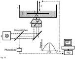
- a voltage signal is generated which is dependent on the position of the focal region relative to the substrate or the desired anchor point. This should be done when meeting the anchor point with the Focus to reach a certain level, preferably a maximum. This can be done, for example, by the method of the back reflection in the beam path, as shown Fig. 12 seen.
- these Before introducing the structuring laser or the pulses, for example, these pass through a glass plate which is initially not relevant for the propagation of these pulses. The radiation is then focused as usual into the material. Depending on the Z position, a small portion of the pulses is reflected back because there is a refractive index contrast between the substrate and liquid resist material. This reflection is maximal when the substrate / resist interface is optimally hit. Then the back reflection is tapped with the glass plate, which deflects a part of it onto a photodiode.
- such a topography image can be obtained, namely, by repeating this maximizing the back-reflection at many points on the substrate and storing the Z-positions at which the maxima occur.
- the laser used for the structuring may possibly be used as the radiation source.
- its power is advantageously set very low in order to eliminate the risk of causing the intended for the return reflection light beam unwanted solidification of bath material. It may be cheaper, however, to use a second laser that does not interact with the resist and is focused at the same point as the patterning laser.
- by means of regulation it is also possible to ensure that a specific signal level of the back-reflection is always maintained by compensating the Z position, while the focus is moved in the plane. This can be done with well-known rules such as PI or PID.
- the focal point is moved relative to the substrate in the XY plane and thus the focus position in Z changes relative to the substrate and thus the signal of the back reflection
- the difference between the target value (the voltage signal in the maximum) and the (dynamic) actual must Value are regulated.
- mathematical calculations are carried out to transmit a signal to the control element (the Z-axis), which approaches the actual value to the setpoint.
- P proportional
- I integral
- D differential
- a PI controller combines the advantage of the P-controller, namely fast response, with the advantage of the I-controller, the exact compensation.
- a PI-controlled circle is therefore accurate and medium fast.
- a PID controller combines the good features of all three types of controllers. The PID controlled circuit is accurate and very fast. Therefore, a PID controller is well suited for the invention.
- the positioning accuracy of at least one or each movement axis is preferably at least 0.20 ⁇ m.
- a positioning device with at least one rotatable axis can be used.
- either the material to be consolidated or a carrier unit immersed in it can be rotated about at least one spatial axis.
- Substrates in the form of rolled-up films or the like can be used, which then act as carrier units or are positioned by means of such.
- the film-like substrates can be guided over the rotational positioning and positioned relative to the at least one laser focus.
- the rotational positioning is preferably carried out with a resolution of at least 0.079 seconds of arc and / or an accuracy of at least 3 micro-arc seconds.
- the maximum rotational speed is preferably about 300 revolutions per minute with a repeatability of less than 2 seconds of arc.
- the positioning system has the following properties: the travel preferably in each direction is preferably at least 150 mm, in particular in each spatial direction.
- the positioning accuracy is preferably ⁇ 0.20 ⁇ m in each direction.
- the accuracy in the repeated approach of a point is ⁇ 0.05 ⁇ m.
- the accuracy perpendicular to the direction of movement in the horizontal plane is in particular ⁇ 0.25 ⁇ m and the accuracy perpendicular to the direction of movement in the vertical plane ⁇ 0.25 ⁇ m.
- the traversing speed of the positioning system is up to 300 mm / s (lower speeds are also possible), with a maximum linear acceleration with load freedom of approx. 10 m / s 2 .
- solid-state lasers, diode-pumped solid-state lasers, semiconductor lasers, fiber lasers, etc. of any desired wavelength can be used as the beam source.
- an ytterbium laser system is used. Its wavelength is at frequency doubling in the range of green light.
- the advantage of ytterbium lasers over Ti-sapphire laser systems, which have a wavelength of approx. 800 nm, is the wavelength of 1030 nm. This is at frequency doubling in the green range at 515nm, which can lead to an improved resolution.
- the materials that can be structured can be processed more efficiently than with lasers in wavelength ranges of approximately 800 nm.
- the process window is significantly larger in terms of material formulations.
- a Ti-sapphire laser is at frequency doubling with disadvantage in the UV range at about 400nm.
- this spectral range is so rich in energy, that exposure of most of the material systems to be solidified would already result in a 1PP process, which can be avoided by using longer wavelength laser systems.
- Another disadvantage of Ti-sapphire lasers is that the laser pulses are usually too short a duration. Although this would result in a higher process efficiency, but it also creates problems because short pulses have a very wide range and more aberrations occur. In general, short pulses are harder to handle, which can lead to higher costs and time.
- ytterbium laser systems are basically possible. It is advantageous that you can pump these lasers with diodes and no additional pump laser and various other instruments are necessary.
- Advantage of ytterbium lasers over Nd: YAG lasers are relatively short pulses. While ytterbium lasers can achieve pulses well below one picosecond, the pulse lengths of a Nd: YAG laser are typically greater than one picosecond, and thus less favorable for triggering non-linear absorption, since there is a risk of weakly networked and labile structures. which can lead to the disadvantages described above.
- the pulse durations required to efficiently initiate non-linear absorption are less than one picosecond.
- photoinitiators may additionally be used.
- the repetition rate is preferably adjustable between 1 kHz and 80 MHz, preferably between 10 kHz and 80 MHz.
- wavelengths in the UV range, in the visible range and in the infrared range can be used.
- the lasers may in particular have powers between 100 mW and 5 W, preferably between 150 mW and 2 W and / or a pulse duration of less than 1 picosecond and / or a repetition rate between 1 and 80 MHz.
- the division of the laser beam or the spatial beam shaping can take place in different ways. It can be effected by using passive DOEs (diffractive optical elements) such as, for example, phase or amplitude masks, or microlens arrays or active, preferably dynamically adaptable, DOEs, as well as combinations of these elements. It can thus be any intensity distributions, such as multiple focal points or arbitrarily shaped foci are generated, which allow the writing of a structure with several possibly shaped focal points. Particularly advantageous are DOEs for phase modulation, since these have no or only low power losses in comparison to DOEs with amplitude masks. It is also possible to use active (transmittive or reflective) spatial light modulators. As a mask can with advantage a one-dimensional grid with a grid spacing of preferably less than 10 ⁇ m or a two-dimensional array with a pixel spacing of preferably less than 10 ⁇ m.
- focusing optics can also find multiple focusing optics use. These can then be moved relative to the carrier material (substrate) so that several structures with one focal point each can be written simultaneously.
- the use of multiple focusing optics requires the splitting of the laser power by conventional beam splitters into a plurality of beams, which are each guided to a focusing optics.
- a combination of the above beamforming is possible by first a modulator generates the desired intensity distribution of the radiation and this is then focused by a plurality of optics. Likewise, one modulator or one mask per focusing optics can also be used in each case. This variant makes it possible to write several structures with several focal points at the same time.
- Each focusing optics may be movable relative to other elements of the beam guide and / or the material container and / or the material to be consolidated and / or the carrier unit, so that only the focusing optics alone must be moved for positioning and remaining elements of the beam guide can be permanently installed.
- the laser radiation can be performed with particular advantage at least in partial areas of the beam guide via optical waveguides.
- hybrid optics comprising diffractive optical elements and conventional lenses can be used according to the invention.
- the diffractive optical elements are for example made of quartz glass, organopolysiloxane-containing materials, liquids or any combination of materials.
- the use of focusing optics which are used without refractive index matching gives a positioning error due to refraction at the air-material interface (that is, the movement of the focal point does not coincide with the movement of the optics with variable penetration depths of the light into the material ) arises. This deviation in the Z-positioning of the focal point can be achieved via a correction factor, for. B. via a machine software, be compensated.
- the apparatus and method of the present invention are not limited by diffraction limitations of the focusing optics because, on the one hand, there is a different absorption behavior from linear one-photon absorption and, on the other hand, a threshold process is utilized.
- the absorption profile (approximately Gaussian profile) in the case of multiphoton absorption is furthermore narrower, as a result of which better resolution is possible since there is a nonlinear relationship between the photon density and the absorption behavior.
- the absorption behavior of the one-photon absorption is characterized by linearity compared to the photon density and by classical Physics is explainable, finds the simultaneous absorption of two or more photons their justification in quantum mechanics.
- the device may comprise a dispenser system for in situ deposition of the material to be solidified.
- a dispenser system for in situ deposition of the material to be solidified.
- Such a system advantageously allows material to be solidified to be added to the material bath in accordance with the respective process status. This has the positive effect, in particular in the production of large bodies or structures down to the milli- or centimeter range, that at the beginning of the production only so much material has to be present in the bath as is necessary to produce the first voxel. Only in the course of further production and with waxing of the body, further material to be solidified is supplied via the dispenser system, preferably always only in the quantity necessary for producing the next voxel.
- the bath is always filled only with the necessary for the current generation of voxels amount of material to be solidified, which has the advantage that in a positioning movement of the bath only a relatively small mass is to move and positioning a movement of a immersed in the material optics this must not be moved deeply immersed in the material, whereby flow resistance and turbulence in the bathroom are largely prevented, which positively affects the quality of the body produced.
- the dispenser system can have freely addressable nozzles which allow a locally definable supply of material to be solidified, as a result of which material savings result in a considerable cost reduction and resource conservation in the production of functional elements.
- the dispenser system preferably has a high positioning accuracy in the micrometer range. The procedure described above is basically possible manually without the use of a dispenser system.
- the device may comprise a scanner system, in particular a 3D scanner, or may be used in the method such.
- a scanner system in particular a 3D scanner
- the data thus obtained can be used to simply write complex shaped bodies and structures directly into the machine into the material to be consolidated.
- structures fabricated with the device may serve as a master structure for other impression techniques be used. It is intended both a single use and a multiple use of the same master.
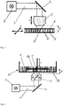
- a device for explaining the invention is shown schematically.
- the device according to this figure has a laser source 1, a deflection mirror 2 as part of a beam guide and a focusing optics 3.
- the emerging from the laser source 1 unfocused laser beam 4 is passed through the deflection mirror 2 to the focusing optics 3. There he is focused in a focus 5.
- Fig. 1 is schematically indicated, consisting of lower support 7 and upper support 8 material intake with the intermediate material to be solidified 6 relative to the focus 5 and the focusing optics. 3 Positionable in the X and Y directions, while the focusing optics 3 can be positioned relative to the material 6 in the Z direction.
- Fig. 1 shows the arrangement of the focusing optics 3 relative to the material to be solidified 6 at the beginning of a solidification cycle.
- the focus 5 directly adjoins the lower carrier 7, so that solidified material attaches to the carrier 7 in the focal region.
- This initial positioning is required to solidify the material positionably fixed in the course of further solidification, otherwise no defined structures can be built up.
- the distance between the respective top of lower support 7 and upper support 8 must be smaller than the working distance 9 of the focusing optics 3. Otherwise, it is not possible to position the focus 5 on the lower support 7 and there to accumulate solidified material.
- Fig. 2 shows a first embodiment of the invention, in which an exposure of the material to be solidified through a material container 10 takes place therethrough.
- an unfocused laser beam 4 generated in the laser source 1 is passed via a deflection mirror 2 to an arranged below the material container 10 focusing optics 3.
- the deflecting mirror 2 can be designed to be positionable. The beam is focused by this in the recorded in the material container 10 to be solidified material 6.
- the maximum depth in which the focus can be introduced into the material to be solidified 6, limited by the working distance 9 of the focusing optics 3.
- the in Fig. 2 illustrated device on a positionable relative to the material container 10 carrier unit 12.
- the carrier unit 12 is immersed in the material container 10 to be solidified material 6.
- the carrier unit 12 can be positioned in the Z direction, while the focusing optics 3 can be positioned in the X and Y directions.
- Fig. 2 is also exemplified the beginning of the generation of a structure.
- the carrier unit 12 is positioned relative to the material container 10 and focus 5 such that the focus is adjacent to the lower surface of the carrier unit 12.
- the support unit 12 can be positioned in the Z direction, so that the focus comes to rest on an interface already solidified material and subsequently solidified material attaches to already solidified material and adheres there.
- the focusing optics 3 By positioning the focusing optics 3 in the X and Y directions and corresponding introduction of laser pulses, the position of the solidification in the X or Y direction is determined.
- the carrier unit which can be positioned in the Z direction and the corresponding process guidance make it possible to solidify structures whose dimensions are independent and, in particular, greater than the working distance 9 of the focusing optics 3 used.
- Fig. 5 shows another device in a further schematic representation.
- the device in turn has a laser source 1, wherein an unfocused laser beam 4 exiting therefrom is guided via a deflecting mirror 2 to a focusing optics 3. It also has a material container 10 with material 6 to be consolidated and a carrier unit 12. This is not movable in the example shown, but in principle can be positioned in one or more directions.
- the focusing optics 3 has a housing 14 with a beam exit surface 13 and can be positioned in the three spatial directions X, Y and Z in the example shown. By immersing the focusing optics 3 whose beam output surface 13 forms an optically defined interface to be solidified material 6, whereby a defined and accurate introduction of the laser radiation in the material to be solidified 6 is possible.
- Fig. 5 again shows the device at the beginning of a structuring process, in which the focusing optics 3 is arranged relative to the carrier unit 12 at the working distance 9, so that the focus 5 is adjacent to the surface of the carrier unit 12.
- the structuring can be carried out by appropriate positioning of the focusing optics 3 in the Z-direction matched to the thickness of already solidified material adhering to the carrier unit 12.
- the height of the producible structures is not limited by the working distance 9 of the focusing optics 3.
- the present invention uses for all possible embodiments high NA focusing optics 3, at least NA greater than 0.25, to achieve the desired high resolution or small voxels.
- the working distances 9 of the objectives are preferably between 0.1 and 100 mm, more preferably between 1 and 10 mm. It should be emphasized that of course the focus area 5 of the focusing optics in Inside the bath 10 must lie. Therefore, when choosing the correct working distance and the thickness of the transparent bath floor, which must be penetrated to take into account. It is favorable to choose the thickness of the bath floor in the range of 0.1 to 20 mm, preferably in the range of 0.5 to 5 mm. For the distance from focus area 5 to the bottom of the bath, values of 0.1 to 2 mm are most favorable.
- the focusing optics are moved according to the invention at least in one plane (usually the horizontal, ie the XY plane), the size of the selected NA is not necessarily important, at least for a minimum value of 0.25.
- the coupling of the laser beam in the focusing optics is carried out according to the invention preferably via a system of mirrors, as shown in the FIG. 12 is shown.
- Fig. 8 shows a device that is of its construction substantially according to the embodiment Fig. 5 equivalent.
- a beam-shaping element 15 for example, in the form of a phase or amplitude mask in the beam path between deflecting mirror 2 and focusing optics 3 is arranged.
- the laser radiation is focused via the focusing optics 3 into a plurality of foci 5a, 5b and 5c, so that material 6 to be solidified can be solidified at several points at the same time.
- the number of solidification points corresponds to the number n of foci produced (parallelization).
- Fig. 9 shows a corresponding use of a beam-shaping element 15 in the context of a device according to the embodiment of Fig. 2 , To the above description of Fig. 2 is referred to.
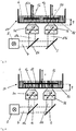
- FIG. 3, 4 . 6 and 7 Other devices with parallelization are in the Fig. 3, 4 . 6 and 7 shown.
- the parallelization is achieved in each case by using a semitransparent deflecting mirror 16, which divides the out of the laser source 1 unfocused laser beam 4 into two partial beams 17a, 17b, which are each directed to an independent focusing optics 3.
- the devices according to the Fig. 3 and 6 have two immersed in the material to be solidified 6 support units 12a and 12b, which can be positioned together or independently of each other in the Z direction. With these devices, structures of different geometry can be generated simultaneously by appropriate control of the positioning axes.
- the Fig. 4 and 7 show devices in which by means of parallelization in several places can be written simultaneously on a support unit 12, which is immersed in the material to be solidified.
- a turntable 18 is used here, in addition to or alternatively to a linear positioning a rotational positioning z. B. allows a rotation axis 19.
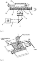
- the Indian Fig. 10 shown turntable 18 is used to position a film-shaped carrier unit to be solidified material 6 relative to the focus. 5
- a device rotatable about a rotation axis 19 and linearly positionable in the Z direction carrier unit 12 immersed in a bath of material to be solidified.
- the focusing optics 3 can be linearly positioned in the X and Y directions. The focal position is adjusted so that material 6 solidifies on the carrier unit 12, separates and is quasi wound up.
Landscapes
- Engineering & Computer Science (AREA)
- Chemical & Material Sciences (AREA)
- Materials Engineering (AREA)
- Manufacturing & Machinery (AREA)
- Physics & Mathematics (AREA)
- Optics & Photonics (AREA)
- Mechanical Engineering (AREA)
- Plasma & Fusion (AREA)
- Health & Medical Sciences (AREA)
- Toxicology (AREA)
Claims (13)
- Dispositif de production de structures tridimensionnelles en un matériau à solidifier (6), en particulier en un matériau contenant des organopolysiloxanes, par solidification localement sélective de celui-ci à la suite d'une réticulation organique induite par la lumière, présentant:une source laser (1),une optique de focalisation mobile (3) pour la formation d'un ou de plusieurs foyer(s) laser (5) et un réservoir de matériau (10) pour le matériau à solidifier, dans lequel la source laser et l'optique de focalisation sont conçues pour la production d'impulsions laser ou de suites d'impulsions laser, qui déclenchent à leur foyer une polymérisation à deux photons ou plus, et dans lequel l'optique de focalisation présente une ouverture numérique de > 0,25,dans lequel le réservoir de matériau se compose au moins en partie d'un matériau perméable au rayonnement laser utilisé et est ou peut être disposé dans le trajet des rayons, de telle manière que le rayonnement laser puisse être introduit à travers le réservoir de matériau dans le matériau à solidifier, dans lequel le réservoir de matériau reste immobile et agit comme face limite optiquement définie,dans lequel une unité de support (12), qui peut être positionnée par rapport au réservoir de matériau, est disposée dans celui-ci, etun système de détection optique pour mesurer une structure déjà introduite dans le matériau et/ou l'unité de support (12) agissant en tant que substrat.
- Dispositif selon la revendication 1, caractérisé en ce que l'optique de focalisation est déplaçable au moins dans un plan horizontal (X-Y).
- Dispositif selon l'une quelconque des revendications précédentes, caractérisé en ce que l'optique de focalisation (3) possède une ouverture numérique de > 0,5 et de préférence de > 1,0.
- Dispositif selon l'une quelconque des revendications précédentes, caractérisé en ce que la distance de travail entre un objectif de l'optique de focalisation (3) et le foyer laser correspondant se situe entre 0,1 et 100 mm, de préférence entre 1 et 10 mm.
- Dispositif selon l'une quelconque des revendications précédentes, caractérisé en ce qu'il présente une optique (16) pour la distribution spatiale du faisceau laser (17a, 17b) et la production d'au moins deux foyers laser (5a, 5b) ou de maxima d'intensité spatialement espacés l'un de l'autre.
- Dispositif selon la revendication 5, caractérisé en ce que le système de détection présente une source de lumière ainsi qu'un système de détection électronique.
- Dispositif selon la revendication 6, caractérisé en ce que le système de détection détecte au moins partiellement la topographie de l'unité de support et est relié à un système de régulation, qui détecte des points de la surface s'écartant éventuellement de la valeur de consigne, de telle manière que ceux-ci soient commandés optiquement de façon correcte.
- Dispositif selon l'une quelconque des revendications précédentes, présentant en outre un système de distributeur pour le dépôt in situ pour le matériau à solidifier.
- Procédé de production de structures tridimensionnelles en un matériau à solidifier (6), en particulier en un matériau contenant des organopolysiloxanes, par solidification localement sélective de celui-ci à la suite d'une réticulation organique induite par la lumière en raison d'une irradiation au moyen d'un laser (1), dans lequel on a disposé ou on dispose le matériau à solidifier dans un réservoir de matériau (10), le réservoir de matériau est au moins localement perméable au laser utilisé et n'est pas déplacé pendant le procédé, on positionne à l'aide d'une optique de focalisation déplaçable (3) avec une ouverture numérique > 0,25 une impulsion laser ou une suite d'impulsions laser à travers le réservoir de matériau dans le matériau à solidifier sur au moins un foyer laser (5) de telle manière que le réservoir de matériau forme une face limite optiquement définie, par laquelle on introduit le laser dans le matériau à solidifier,
dans lequel l'impulsion laser ou la suite d'impulsions laser déclenche à son foyer une polymérisation à deux photons ou plus du matériau à solidifier, de telle manière que l'on n'atteigne des conditions de solidification que dans les environs immédiats dudit au moins un foyer laser en raison de l'intensité locale, de telle manière que pendant la durée de l'impulsion laser ou de la suite d'impulsions laser un élément de volume du matériau à solidifier soit solidifié par foyer,
dans lequel on positionne dans le matériau à solidifier une unité de support (12) par rapport audit au moins un foyer laser, de telle manière que le matériau à solidifier se dépose lors de la solidification sur l'unité de support ou sur du matériau déjà solidifié sur l'unité de support, dans lequel l'unité de support peut être positionnée par rapport au réservoir de matériau, et
dans lequel on mesure une structure déjà introduite dans le matériau et/ou l'unité de support agissant comme substrat in situ avec un système de détection. - Procédé selon la revendication 9, caractérisé en ce que l'optique de focalisation est déplaçable au moins dans un plan horizontal (X-Y).
- Procédé selon une des revendications 9 ou 10, caractérisé en ce que l'on divise un faisceau laser en au moins deux faisceaux partiels (17a, 17b) et/ou on produit au moins deux foyers laser (5a, 5b) ou des maxima d'intensité spatialement espacés l'un de l'autre.
- Procédé selon l'une quelconque des revendications 9 à 11, caractérisé en ce que l'on fournit le matériau à solidifier in situ au réservoir de matériau au moyen d'un système de distributeur.
- Procédé selon la revendication 9, caractérisé en ce que l'unité de support est une bande de support, qui est déroulée d'un rouleau, tirée (direction X) à travers le matériau à solidifier dans le réservoir de matériau et de nouveau enroulée après l'enlèvement de la/des structure(s) tridimensionnelle(s) produite(s) sur celle-ci, dans lequel le mouvement de traction est effectué de façon discontinue ou continue.
Priority Applications (1)
| Application Number | Priority Date | Filing Date | Title |
|---|---|---|---|
| EP17171209.4A EP3225383B1 (fr) | 2010-05-11 | 2011-05-11 | Dispositif et procédé de production de structures tridimensionnelles |
Applications Claiming Priority (3)
| Application Number | Priority Date | Filing Date | Title |
|---|---|---|---|
| DE102010020158A DE102010020158A1 (de) | 2010-05-11 | 2010-05-11 | Vorrichtung sowie Verfahren zur Erzeugung dreidimensionaler Strukturen |
| PCT/EP2011/057640 WO2011141521A1 (fr) | 2010-05-11 | 2011-05-11 | Dispositif et procédé de production de structures tridimensionnelles |
| EP11721021.1A EP2569140B1 (fr) | 2010-05-11 | 2011-05-11 | Dispositif et procédé de production de structures tridimensionnelles |
Related Parent Applications (2)
| Application Number | Title | Priority Date | Filing Date |
|---|---|---|---|
| EP11721021.1A Division-Into EP2569140B1 (fr) | 2010-05-11 | 2011-05-11 | Dispositif et procédé de production de structures tridimensionnelles |
| EP11721021.1A Division EP2569140B1 (fr) | 2010-05-11 | 2011-05-11 | Dispositif et procédé de production de structures tridimensionnelles |
Related Child Applications (2)
| Application Number | Title | Priority Date | Filing Date |
|---|---|---|---|
| EP17171209.4A Division EP3225383B1 (fr) | 2010-05-11 | 2011-05-11 | Dispositif et procédé de production de structures tridimensionnelles |
| EP17171209.4A Division-Into EP3225383B1 (fr) | 2010-05-11 | 2011-05-11 | Dispositif et procédé de production de structures tridimensionnelles |
Publications (2)
| Publication Number | Publication Date |
|---|---|
| EP2905121A1 EP2905121A1 (fr) | 2015-08-12 |
| EP2905121B1 true EP2905121B1 (fr) | 2019-08-21 |
Family
ID=44504313
Family Applications (3)
| Application Number | Title | Priority Date | Filing Date |
|---|---|---|---|
| EP11721021.1A Active EP2569140B1 (fr) | 2010-05-11 | 2011-05-11 | Dispositif et procédé de production de structures tridimensionnelles |
| EP15160153.1A Active EP2905121B1 (fr) | 2010-05-11 | 2011-05-11 | Dispositif et procédé de production de structures tridimensionnelles |
| EP17171209.4A Active EP3225383B1 (fr) | 2010-05-11 | 2011-05-11 | Dispositif et procédé de production de structures tridimensionnelles |
Family Applications Before (1)
| Application Number | Title | Priority Date | Filing Date |
|---|---|---|---|
| EP11721021.1A Active EP2569140B1 (fr) | 2010-05-11 | 2011-05-11 | Dispositif et procédé de production de structures tridimensionnelles |
Family Applications After (1)
| Application Number | Title | Priority Date | Filing Date |
|---|---|---|---|
| EP17171209.4A Active EP3225383B1 (fr) | 2010-05-11 | 2011-05-11 | Dispositif et procédé de production de structures tridimensionnelles |
Country Status (8)
| Country | Link |
|---|---|
| US (3) | US20130056910A1 (fr) |
| EP (3) | EP2569140B1 (fr) |
| DE (2) | DE102010020158A1 (fr) |
| DK (1) | DK2569140T3 (fr) |
| ES (2) | ES2543028T3 (fr) |
| HK (1) | HK1244467A1 (fr) |
| LT (1) | LT2905121T (fr) |
| WO (1) | WO2011141521A1 (fr) |
Cited By (1)
| Publication number | Priority date | Publication date | Assignee | Title |
|---|---|---|---|---|
| WO2025131180A1 (fr) | 2023-12-23 | 2025-06-26 | Christian-Albrechts-Universität Zu Kiel | Procédé et utilisation de polymérisation multiphotonique en phase gazeuse |
Families Citing this family (64)
| Publication number | Priority date | Publication date | Assignee | Title |
|---|---|---|---|---|
| DE102011012484B4 (de) | 2011-02-25 | 2025-08-14 | Nanoscribe Holding Gmbh | Verfahren und Vorrichtung zum ortsaufgelösten Einbringen eines Intensitätsmusters aus elektromagnetischer Strahlung in eine photosensitive Substanz sowie Verwendung hiervon |
| BE1020596A3 (nl) * | 2012-03-27 | 2014-01-07 | Materialise Nv | Werkwijze voor het verminderen van differentiële krimp bij stereolithografie. |
| DE102012021284B4 (de) * | 2012-10-29 | 2014-12-04 | Fraunhofer-Gesellschaft zur Förderung der angewandten Forschung e.V. | Vorrichtung und Verfahren zur schichtweisen Herstellung von Bauteilen mittels Photopolymerisation |
| HK1217366A1 (zh) | 2013-01-11 | 2017-01-06 | Multiphoton Optics Gmbh | 光学组件及其制备方法 |
| DE102013104600B4 (de) | 2013-01-11 | 2019-10-17 | Fraunhofer-Gesellschaft zur Förderung der angewandten Forschung e.V. | Schichten oder dreidimensionale Formkörper mit zwei Bereichen unterschiedlicher Primär- und/oder Sekundärstruktur, Verfahren zur Herstellung des Formkörpers und Materialien zur Durchführung dieses Verfahrens |
| US9517128B2 (en) * | 2013-03-08 | 2016-12-13 | The Trustees Of Princeton University | Multi-functional hybrid devices/structures using 3D printing |
| BE1024052B1 (nl) * | 2013-12-03 | 2017-11-08 | Layerwise N.V. | Werkwijze en inrichting voor het kalibreren van meerdere energiestralen voor het additief vervaardigen van een object |
| GB2521396A (en) * | 2013-12-18 | 2015-06-24 | Skf Ab | A machine for grinding a work-piece |
| US10086566B2 (en) * | 2014-01-02 | 2018-10-02 | Old World Labs | Apparatus for production of three-dimensional objects by stereolithography |
| EP3119589A4 (fr) * | 2014-03-21 | 2017-11-08 | Laing O'Rourke Australia Pty Limited | Procédé et appareil pour la fabrication d'un objet |
| US10545458B2 (en) * | 2014-03-24 | 2020-01-28 | B.G. Negev Technologies And Applications Ltd., At Ben Gurion University | Optical sectioning using a phase pinhole |
| US20150343664A1 (en) * | 2014-05-27 | 2015-12-03 | Jian Liu | Method and Apparatus for Three-Dimensional Additive Manufacturing with a High Energy High Power Ultrafast Laser |
| WO2015191257A1 (fr) * | 2014-06-12 | 2015-12-17 | General Electric Company | Procédé de fabrication additif par fusion au laser sélective avec multiples faisceaux de laser de fusion simultanés et appareil pour ce dernier |
| WO2015197495A1 (fr) | 2014-06-27 | 2015-12-30 | Koninklijke Philips N.V. | Dispositif et procédé d'impression pour l'impression 3d |
| WO2016013038A1 (fr) * | 2014-07-23 | 2016-01-28 | Millennium Art S.R.L. | Machine de stéréolithographie présentant une productivité élevée |
| US20180029299A1 (en) * | 2015-02-26 | 2018-02-01 | Stratasys, Inc. | Additive manufacturing with offset stitching |
| DE102015003652B4 (de) * | 2015-03-20 | 2017-03-16 | Universität Stuttgart | Verfahren zum Verbinden einer optischen Festkernfaser mit einer weiteren optischen Faser und optische Festkernfaser mit Fügungsvorrichtung |
| DE102015207180A1 (de) * | 2015-04-21 | 2016-10-27 | Siemens Aktiengesellschaft | Verfahren und Vorrichtung zum schichtweisen Herstellen dreidimensionaler Strukturen |
| US10442175B2 (en) * | 2015-04-28 | 2019-10-15 | Warsaw Orthopedic, Inc. | 3D printing devices and methods |
| WO2016184888A1 (fr) * | 2015-05-19 | 2016-11-24 | Addifab Aps | Installation de fabrication additive avec source de rayonnement partagée |
| EP3130950A1 (fr) | 2015-08-10 | 2017-02-15 | Multiphoton Optics Gmbh | Élement de deviation de rayonnement et element optique dote d'un element de deviation de rayonnement |
| HU230841B1 (hu) * | 2015-08-14 | 2018-08-28 | Marton Bartos | Berendezés és eljárás háromdimenziós tárgy elõállítására |
| FI129702B (en) | 2015-10-09 | 2022-07-15 | Inkron Ltd | Three dimensional printing materials and method for making a 3D printed article |
| WO2017075258A1 (fr) * | 2015-10-30 | 2017-05-04 | Seurat Technologies, Inc. | Système et procédé de fabrication additive |
| US11141919B2 (en) | 2015-12-09 | 2021-10-12 | Holo, Inc. | Multi-material stereolithographic three dimensional printing |
| US20170225393A1 (en) * | 2016-02-04 | 2017-08-10 | Global Filtration Systems, A Dba Of Gulf Filtration Systems Inc. | Apparatus and method for forming three-dimensional objects using two-photon absorption linear solidification |
| EP3208075B1 (fr) * | 2016-02-17 | 2018-06-13 | Hochschule für angewandte Wissenschaften Aschaffenburg | Procédé optique et appareil de fabrication d'un objet structuré |
| US10239157B2 (en) * | 2016-04-06 | 2019-03-26 | General Electric Company | Additive machine utilizing rotational build surface |
| ES2791418T3 (es) | 2016-07-07 | 2020-11-04 | Univ Wien Tech | Procedimiento y dispositivo para la fabricación generativa basada en litografía de componentes tridimensionales |
| US11883903B2 (en) * | 2016-07-25 | 2024-01-30 | Amplitude | Method and appliance for cutting materials by multi-beam femtosecond laser |
| EP3287263A1 (fr) | 2016-08-26 | 2018-02-28 | Multiphoton Optics Gmbh | Dispositif et procede de traitement par laser de corps ou de surfaces |
| EP3287262A1 (fr) | 2016-08-26 | 2018-02-28 | Multiphoton Optics Gmbh | Dispositif et procede de traitement par laser de corps ou de surfaces |
| EP3290188A1 (fr) * | 2016-08-30 | 2018-03-07 | Lithoz GmbH | Procédé de consolidation d'un matériau réfléchissant de manière diffuse et photopolyméralisable. |
| DE102017213072B4 (de) | 2016-09-05 | 2024-11-14 | Ford Global Technologies, Llc | Additives Fertigungsverfahren |
| FR3056593B1 (fr) * | 2016-09-28 | 2020-06-26 | Ecole Centrale De Marseille | Procede pour la realisation d’un objet tridimensionnel par un processus de photo-polymerisation multi-photonique et dispositif associe |
| WO2018206995A1 (fr) * | 2017-05-10 | 2018-11-15 | Elkem Silicones France Sas | Procédé de fabrication d'un article en élastomère de silicone à l'aide d'une imprimante 3d |
| GB2564956B (en) | 2017-05-15 | 2020-04-29 | Holo Inc | Viscous film three-dimensional printing systems and methods |
| US10245785B2 (en) | 2017-06-16 | 2019-04-02 | Holo, Inc. | Methods for stereolithography three-dimensional printing |
| EP3646115A1 (fr) * | 2017-06-30 | 2020-05-06 | Nikon Corporation | Procédé pour fabriquer un article fait d'un matériau polymérisé |
| EP3431262A1 (fr) * | 2017-07-21 | 2019-01-23 | CL Schutzrechtsverwaltungs GmbH | Installation de fabrication additive d'objets tridimensionnels |
| DE102018201901A1 (de) | 2018-02-07 | 2019-08-08 | Ford Global Technologies, Llc | Vorrichtung und Verfahren zur additiven Fertigung dreidimensionaler Strukturen |
| FR3079517B1 (fr) * | 2018-03-28 | 2021-01-01 | Ecole Centrale Marseille | Procede pour la realisation d’un objet tridimensionnel par un processus de photo-polymerisation multi-photonique et dispositif associe |
| US10875094B2 (en) * | 2018-03-29 | 2020-12-29 | Vulcanforms Inc. | Additive manufacturing systems and methods |
| CN110467149B (zh) * | 2018-05-10 | 2024-08-13 | 安世亚太科技股份有限公司 | 一种碳基功能器件及其制备方法 |
| US10690486B2 (en) | 2018-07-03 | 2020-06-23 | Amo Development, Llc | Water-immersed high precision laser focus spot size measurement apparatus |
| JP7151033B2 (ja) * | 2018-10-12 | 2022-10-12 | 公益財団法人レーザー技術総合研究所 | 光学素子製造方法 |
| CN109501245A (zh) * | 2018-10-19 | 2019-03-22 | 上海光琢科技有限公司 | 基于脉冲式曝光的光固化3d打印方法 |
| GB201817823D0 (en) * | 2018-10-31 | 2018-12-19 | Ge Healthcare Uk Ltd | Improvements in and relating to polymer membranes |
| WO2020094595A1 (fr) * | 2018-11-06 | 2020-05-14 | Ecole Polytechnique Federale De Lausanne (Epfl) | Procédés et appareil de fabrication additive tomographique avec une source de lumière spatialement cohérente |
| DE102018128418B3 (de) * | 2018-11-13 | 2019-11-14 | Nanoscribe Gmbh | Verwendung eines Dispenser-Aufsatzes und Dispenser-Aufsatz für eine Vorrichtung zum Schreiben von 3D-Strukturen mittels Laserlithografie |
| DE102018221670A1 (de) | 2018-12-13 | 2020-06-18 | Karlsruher Institut für Technologie | Vorrichtung und Verfahren zur optischen Charakterisierung oder Bearbeitung eines Objekts |
| CN117067579A (zh) | 2018-12-26 | 2023-11-17 | 霍洛公司 | 用于三维打印系统和方法的传感器 |
| JP7170902B2 (ja) * | 2019-03-27 | 2022-11-14 | スリーディー システムズ インコーポレーテッド | 精密物品のプリントのための高生産性システム |
| EP3792039A1 (fr) * | 2019-09-10 | 2021-03-17 | Nederlandse Organisatie voor toegepast- natuurwetenschappelijk Onderzoek TNO | Tête de distribution pour fabrication d'additif de type à filament fusionné et renforcé par des fibres continues |
| CA3156010A1 (fr) * | 2019-09-27 | 2021-04-01 | Prellis Biologics, Inc. | Organes, dispositifs et matrices imprimes tridimensionnels |
| AT523200B1 (de) * | 2019-11-20 | 2021-10-15 | Univ Graz Tech | Vorrichtung zur additiven fertigung |
| US12172373B2 (en) * | 2019-11-26 | 2024-12-24 | Lubbe Steven | Devices, systems, and methods for 3D printing |
| WO2021117004A1 (fr) * | 2019-12-13 | 2021-06-17 | Alcon Inc. | Système et procédé de détermination de problèmes avec des composants optiques |
| US12162074B2 (en) | 2020-11-25 | 2024-12-10 | Lawrence Livermore National Security, Llc | System and method for large-area pulsed laser melting of metallic powder in a laser powder bed fusion application |
| DE102022106696A1 (de) | 2021-03-22 | 2022-09-22 | Polydiagnost Entwicklungs-, Produktions-, Vertriebs-, Und Servicegesellschaft Für Medizinelektronische Diagnostik- Und Therapiegeräte Mbh | Endoskopoptik und Endoskop |
| WO2022225854A1 (fr) | 2021-04-19 | 2022-10-27 | Holo, Inc. | Systèmes et procédés d'impression tridimensionnelle stéréolithographique |
| CN113927897B (zh) * | 2021-09-18 | 2024-03-15 | 深圳摩方新材科技有限公司 | 一种高利用率的多材料树脂3d打印系统和方法 |
| EP4316782B1 (fr) * | 2022-08-01 | 2025-03-12 | UpNano GmbH | Procédé et dispositif de fabrication additive par lithographie d'un composant tridimensionnel |
| CN120002879B (zh) * | 2025-03-31 | 2026-04-21 | 哈尔滨理工大学 | 一种能级可控的小型激光辐照接枝和交联系统及其应用方法 |
Family Cites Families (29)
| Publication number | Priority date | Publication date | Assignee | Title |
|---|---|---|---|---|
| FR2639948B1 (fr) * | 1988-12-05 | 1991-03-22 | Centre Nat Rech Scient | Procede et dispositif de fabrication d'une piece solide tridimensionnelle par phototransformation d'un liquide organique |
| EP0379068A3 (fr) * | 1989-01-18 | 1990-11-28 | Mitsui Engineering and Shipbuilding Co, Ltd. | Procédé et appareil de moulage optique |
| WO1992000185A1 (fr) * | 1990-06-22 | 1992-01-09 | Martin Russell Harris | Guides d'ondes optiques |
| DE4102260A1 (de) * | 1991-01-23 | 1992-07-30 | Artos Med Produkte | Vorrichtung zur herstellung beliebig geformter koerper |
| DE4414775A1 (de) | 1994-04-14 | 1995-10-19 | Eos Electro Optical Syst | Vorrichtung und Verfahren zum Herstellen eines dreidimensionalen Objekts |
| US5922364A (en) | 1997-03-03 | 1999-07-13 | Young, Jr.; Albert C. | Stereolithography layering control system |
| US6020591A (en) | 1997-07-11 | 2000-02-01 | Imra America, Inc. | Two-photon microscopy with plane wave illumination |
| WO1999054784A1 (fr) | 1998-04-21 | 1999-10-28 | University Of Connecticut | Nanofabrication a structure libre utilisant une excitation multiphotonique |
| US6214276B1 (en) | 1999-05-18 | 2001-04-10 | Creo Srl | Method of forming objects from thermosensitive composition |
| US6583381B1 (en) * | 1999-05-24 | 2003-06-24 | Potomac Photonics, Inc. | Apparatus for fabrication of miniature structures |
| DE19957370C2 (de) * | 1999-11-29 | 2002-03-07 | Carl Johannes Fruth | Verfahren und Vorrichtung zum Beschichten eines Substrates |
| US7014988B2 (en) | 2000-06-15 | 2006-03-21 | 3M Innovative Properties Company | Multiphoton curing to provide encapsulated optical elements |
| ATE433129T1 (de) * | 2000-06-15 | 2009-06-15 | 3M Innovative Properties Co | Mikroherstellungsverfahren für organische optische bauteile |
| DE10111422A1 (de) * | 2001-03-09 | 2002-09-26 | Hannover Laser Zentrum | Verfahren und Vorrichtung zur Herstellung eines Formkörpers aus einem durch Bestrahlung zu verfestigenden flüssigen Material |
| US6841340B2 (en) * | 2001-07-13 | 2005-01-11 | Fuji Photo Film Co., Ltd. | Optical fabricating method and apparatus |
| DE10152878B4 (de) | 2001-10-26 | 2007-08-02 | Fraunhofer-Gesellschaft zur Förderung der angewandten Forschung e.V. | Verfahren zum Erzeugen dreidimensionaler Formkörper oder Oberflächen aus organopolysiloxanhaltigen Ausgangsmaterialien durch Laser-Bestrahlung und deren Verwendung |
| DE10235427A1 (de) * | 2002-08-02 | 2004-02-12 | Eos Gmbh Electro Optical Systems | Vorrichtung und Verfahren zum Herstellen von dreidimensionalen Objekten mittels eines generativen Fertigungsverfahrens |
| GB0303070D0 (en) * | 2003-02-11 | 2003-03-19 | Univ Nottingham | A novel method of light assisted fabrication of materials in liquid media |
| JP2004307699A (ja) | 2003-04-09 | 2004-11-04 | Nitto Denko Corp | 親水性基含有樹脂構造体及びその製造方法 |
| FR2859543B1 (fr) | 2003-09-08 | 2005-12-09 | Pascal Joffre | Systeme de fabrication d'un objet a trois dimensions dans un materiau photo polymerisable |
| JP2005084617A (ja) | 2003-09-11 | 2005-03-31 | Fuji Photo Film Co Ltd | 多光子吸収露光方法および装置 |
| US7800014B2 (en) * | 2004-01-09 | 2010-09-21 | General Lasertronics Corporation | Color sensing for laser decoating |
| US7568904B2 (en) * | 2005-03-03 | 2009-08-04 | Laser Solutions Co., Ltd. | Stereolithography apparatus |
| WO2006109355A1 (fr) * | 2005-04-11 | 2006-10-19 | Japan Science And Technology Agency | Procede et dispositif de lithographie laser multifaisceaux pour realisation de microstructures, employant des faisceaux laser de longueurs d'onde differentes |
| JP2007057622A (ja) | 2005-08-22 | 2007-03-08 | Ricoh Co Ltd | 光学素子及びその製造方法、光学素子用形状転写型の製造方法及び光学素子用転写型 |
| US7520740B2 (en) | 2005-09-30 | 2009-04-21 | 3D Systems, Inc. | Rapid prototyping and manufacturing system and method |
| US7551359B2 (en) | 2006-09-14 | 2009-06-23 | 3M Innovative Properties Company | Beam splitter apparatus and system |
| CN100547440C (zh) | 2007-12-05 | 2009-10-07 | 中国科学院电工研究所 | 一种用于双光子微细加工的三维超分辨衍射光学器件及其设计方法 |
| JP5344553B2 (ja) | 2008-09-08 | 2013-11-20 | 国立大学法人九州大学 | 2光子吸収重合性組成物及び光デバイス |
-
2010
- 2010-05-11 DE DE102010020158A patent/DE102010020158A1/de active Pending
-
2011
- 2011-05-11 EP EP11721021.1A patent/EP2569140B1/fr active Active
- 2011-05-11 LT LT15160153T patent/LT2905121T/lt unknown
- 2011-05-11 ES ES11721021.1T patent/ES2543028T3/es active Active
- 2011-05-11 WO PCT/EP2011/057640 patent/WO2011141521A1/fr not_active Ceased
- 2011-05-11 EP EP15160153.1A patent/EP2905121B1/fr active Active
- 2011-05-11 DK DK11721021.1T patent/DK2569140T3/en active
- 2011-05-11 ES ES15160153T patent/ES2754073T3/es active Active
- 2011-05-11 DE DE202011111094.3U patent/DE202011111094U1/de not_active Expired - Lifetime
- 2011-05-11 EP EP17171209.4A patent/EP3225383B1/fr active Active
- 2011-05-11 US US13/696,966 patent/US20130056910A1/en not_active Abandoned
-
2016
- 2016-02-05 HK HK18103364.2A patent/HK1244467A1/zh unknown
-
2017
- 2017-06-16 US US15/625,515 patent/US10836105B2/en active Active
-
2020
- 2020-03-20 US US16/824,799 patent/US20200282650A1/en not_active Abandoned
Non-Patent Citations (1)
| Title |
|---|
| None * |
Cited By (1)
| Publication number | Priority date | Publication date | Assignee | Title |
|---|---|---|---|---|
| WO2025131180A1 (fr) | 2023-12-23 | 2025-06-26 | Christian-Albrechts-Universität Zu Kiel | Procédé et utilisation de polymérisation multiphotonique en phase gazeuse |
Also Published As
| Publication number | Publication date |
|---|---|
| EP3225383B1 (fr) | 2023-06-28 |
| US20200282650A1 (en) | 2020-09-10 |
| EP2569140B1 (fr) | 2015-04-29 |
| US20130056910A1 (en) | 2013-03-07 |
| HK1213528A1 (zh) | 2016-07-08 |
| LT2905121T (lt) | 2019-11-11 |
| US10836105B2 (en) | 2020-11-17 |
| EP2905121A1 (fr) | 2015-08-12 |
| EP2569140A1 (fr) | 2013-03-20 |
| HK1244467A1 (zh) | 2018-08-10 |
| ES2754073T3 (es) | 2020-04-15 |
| DE102010020158A1 (de) | 2011-11-17 |
| DK2569140T3 (en) | 2015-08-03 |
| EP3225383C0 (fr) | 2023-06-28 |
| EP3225383A1 (fr) | 2017-10-04 |
| WO2011141521A1 (fr) | 2011-11-17 |
| DE202011111094U1 (de) | 2019-09-06 |
| US20170282453A1 (en) | 2017-10-05 |
| ES2543028T3 (es) | 2015-08-13 |
Similar Documents
| Publication | Publication Date | Title |
|---|---|---|
| EP2905121B1 (fr) | Dispositif et procédé de production de structures tridimensionnelles | |
| WO2018036930A1 (fr) | Dispositif et procédé d'usinage laser de corps et/ou de surfaces | |
| DE68929292T2 (de) | Aufbringen und Abstreichen von Stereolithografischen Schichten | |
| WO2018036929A1 (fr) | Dispositif et procédé d'usinage laser de corps et/ou de surfaces | |
| DE102012010635B4 (de) | Verfahren zur 3D-Strukturierung und Formgebung von Oberflächen aus harten, spröden und optischen Materialien | |
| DE102011012484B4 (de) | Verfahren und Vorrichtung zum ortsaufgelösten Einbringen eines Intensitätsmusters aus elektromagnetischer Strahlung in eine photosensitive Substanz sowie Verwendung hiervon | |
| EP3266594B1 (fr) | Procédé et dispositif de fabrication générative par lithographie de composants tridimensionnels | |
| EP1499490B1 (fr) | Procede pour creer des corps tridimensionnels ou des surfaces tridimensionnelles par rayonnement laser | |
| DE102012202487A1 (de) | Verfahren zum Aufschmelzen/Sintern von Pulverpartikeln zur schichtweisen Herstellung von dreidimensionalen Objekten | |
| EP2855119A1 (fr) | Procédé de construction d'un moule en trois dimensions | |
| DE10111422A1 (de) | Verfahren und Vorrichtung zur Herstellung eines Formkörpers aus einem durch Bestrahlung zu verfestigenden flüssigen Material | |
| WO2013182913A2 (fr) | Système de stéréolithographie | |
| EP3418033A1 (fr) | Procédé et dispositif de fabrication générative par lithographie de formes tridimensionnelles | |
| DE102017101823A1 (de) | Strukturiertes Komposit aus Matrixmaterial und Nanopartikeln | |
| EP3290188A1 (fr) | Procédé de consolidation d'un matériau réfléchissant de manière diffuse et photopolyméralisable. | |
| WO2020233757A1 (fr) | Procédé et dispositif de génération d'une structure tridimensionnelle comportant au moins une sous-région plane | |
| DE102013021961A1 (de) | Stereolithographie- System | |
| DE102015225300A1 (de) | Verfahren und Anordnungen zur Verringerung der Grenzflächenadhäsion bei der Photopolymerisation | |
| WO2021198835A1 (fr) | Procédé et dispositif de fabrication additive par lithographie d'un composant tridimensionnel | |
| EP4275869B1 (fr) | Procédé et dispositif de génération d'une structure tridimensionnelle dans un fluide lithographique | |
| Mckee et al. | 3D Printing by Two-Photon Polymerization | |
| DE4416901A1 (de) | Vorrichtung und Verfahren zum Herstellen eines dreidimensionalen Objekts | |
| HK1213528B (en) | Device and method for producing three-dimensional structures | |
| Chen et al. | Micro-and nano-fabrication of biodegradable polymers | |
| WO2022175830A1 (fr) | Méthode et dispositif de contrôle d'un dispositif de fabrication additive à base de lithographie |
Legal Events
| Date | Code | Title | Description |
|---|---|---|---|
| PUAI | Public reference made under article 153(3) epc to a published international application that has entered the european phase |
Free format text: ORIGINAL CODE: 0009012 |
|
| AC | Divisional application: reference to earlier application |
Ref document number: 2569140 Country of ref document: EP Kind code of ref document: P |
|
| AK | Designated contracting states |
Kind code of ref document: A1 Designated state(s): AL AT BE BG CH CY CZ DE DK EE ES FI FR GB GR HR HU IE IS IT LI LT LU LV MC MK MT NL NO PL PT RO RS SE SI SK SM TR |
|
| RIN1 | Information on inventor provided before grant (corrected) |
Inventor name: STICHEL, THOMAS Inventor name: STEENHUSEN Inventor name: HOUBERTZ, RUTH |
|
| 17P | Request for examination filed |
Effective date: 20160211 |
|
| RBV | Designated contracting states (corrected) |
Designated state(s): AL AT BE BG CH CY CZ DE DK EE ES FI FR GB GR HR HU IE IS IT LI LT LU LV MC MK MT NL NO PL PT RO RS SE SI SK SM TR |
|
| REG | Reference to a national code |
Ref country code: HK Ref legal event code: DE Ref document number: 1213528 Country of ref document: HK |
|
| STAA | Information on the status of an ep patent application or granted ep patent |
Free format text: STATUS: EXAMINATION IS IN PROGRESS |
|
| 17Q | First examination report despatched |
Effective date: 20170526 |
|
| REG | Reference to a national code |
Ref country code: DE Ref legal event code: R079 Ref document number: 502011016031 Country of ref document: DE Free format text: PREVIOUS MAIN CLASS: B29C0067000000 Ipc: B29C0064135000 |
|
| GRAP | Despatch of communication of intention to grant a patent |
Free format text: ORIGINAL CODE: EPIDOSNIGR1 |
|
| STAA | Information on the status of an ep patent application or granted ep patent |
Free format text: STATUS: GRANT OF PATENT IS INTENDED |
|
| RIC1 | Information provided on ipc code assigned before grant |
Ipc: B29C 64/386 20170101ALI20190129BHEP Ipc: B33Y 10/00 20150101ALI20190129BHEP Ipc: B29C 64/273 20170101ALI20190129BHEP Ipc: B29C 64/135 20170101AFI20190129BHEP Ipc: B33Y 50/02 20150101ALI20190129BHEP Ipc: B33Y 30/00 20150101ALI20190129BHEP |
|
| INTG | Intention to grant announced |
Effective date: 20190220 |
|
| RIN1 | Information on inventor provided before grant (corrected) |
Inventor name: HOUBERTZ, RUTH Inventor name: STICHEL, THOMAS Inventor name: STEENHUSEN, SOENKE |
|
| GRAJ | Information related to disapproval of communication of intention to grant by the applicant or resumption of examination proceedings by the epo deleted |
Free format text: ORIGINAL CODE: EPIDOSDIGR1 |
|
| STAA | Information on the status of an ep patent application or granted ep patent |
Free format text: STATUS: EXAMINATION IS IN PROGRESS |
|
| GRAR | Information related to intention to grant a patent recorded |
Free format text: ORIGINAL CODE: EPIDOSNIGR71 |
|
| GRAS | Grant fee paid |
Free format text: ORIGINAL CODE: EPIDOSNIGR3 |
|
| STAA | Information on the status of an ep patent application or granted ep patent |
Free format text: STATUS: GRANT OF PATENT IS INTENDED |
|
| INTC | Intention to grant announced (deleted) | ||
| GRAA | (expected) grant |
Free format text: ORIGINAL CODE: 0009210 |
|
| STAA | Information on the status of an ep patent application or granted ep patent |
Free format text: STATUS: THE PATENT HAS BEEN GRANTED |
|
| AC | Divisional application: reference to earlier application |
Ref document number: 2569140 Country of ref document: EP Kind code of ref document: P |
|
| AK | Designated contracting states |
Kind code of ref document: B1 Designated state(s): AL AT BE BG CH CY CZ DE DK EE ES FI FR GB GR HR HU IE IS IT LI LT LU LV MC MK MT NL NO PL PT RO RS SE SI SK SM TR |
|
| INTG | Intention to grant announced |
Effective date: 20190716 |
|
| REG | Reference to a national code |
Ref country code: GB Ref legal event code: FG4D Free format text: NOT ENGLISH |
|
| REG | Reference to a national code |
Ref country code: CH Ref legal event code: EP |
|
| REG | Reference to a national code |
Ref country code: DE Ref legal event code: R096 Ref document number: 502011016031 Country of ref document: DE |
|
| REG | Reference to a national code |
Ref country code: AT Ref legal event code: REF Ref document number: 1169224 Country of ref document: AT Kind code of ref document: T Effective date: 20190915 |
|
| REG | Reference to a national code |
Ref country code: IE Ref legal event code: FG4D Free format text: LANGUAGE OF EP DOCUMENT: GERMAN |
|
| RAP2 | Party data changed (patent owner data changed or rights of a patent transferred) |
Owner name: MULTIPHOTON OPTICS GMBH Owner name: FRAUNHOFER-GESELLSCHAFT ZUR FOERDERUNG DER ANGEWAN |
|
| REG | Reference to a national code |
Ref country code: SE Ref legal event code: TRGR |
|
| REG | Reference to a national code |
Ref country code: NL Ref legal event code: FP |
|
| PG25 | Lapsed in a contracting state [announced via postgrant information from national office to epo] |
Ref country code: PT Free format text: LAPSE BECAUSE OF FAILURE TO SUBMIT A TRANSLATION OF THE DESCRIPTION OR TO PAY THE FEE WITHIN THE PRESCRIBED TIME-LIMIT Effective date: 20191223 Ref country code: HR Free format text: LAPSE BECAUSE OF FAILURE TO SUBMIT A TRANSLATION OF THE DESCRIPTION OR TO PAY THE FEE WITHIN THE PRESCRIBED TIME-LIMIT Effective date: 20190821 Ref country code: BG Free format text: LAPSE BECAUSE OF FAILURE TO SUBMIT A TRANSLATION OF THE DESCRIPTION OR TO PAY THE FEE WITHIN THE PRESCRIBED TIME-LIMIT Effective date: 20191121 Ref country code: NO Free format text: LAPSE BECAUSE OF FAILURE TO SUBMIT A TRANSLATION OF THE DESCRIPTION OR TO PAY THE FEE WITHIN THE PRESCRIBED TIME-LIMIT Effective date: 20191121 |
|
| PG25 | Lapsed in a contracting state [announced via postgrant information from national office to epo] |
Ref country code: AL Free format text: LAPSE BECAUSE OF FAILURE TO SUBMIT A TRANSLATION OF THE DESCRIPTION OR TO PAY THE FEE WITHIN THE PRESCRIBED TIME-LIMIT Effective date: 20190821 Ref country code: IS Free format text: LAPSE BECAUSE OF FAILURE TO SUBMIT A TRANSLATION OF THE DESCRIPTION OR TO PAY THE FEE WITHIN THE PRESCRIBED TIME-LIMIT Effective date: 20191221 Ref country code: LV Free format text: LAPSE BECAUSE OF FAILURE TO SUBMIT A TRANSLATION OF THE DESCRIPTION OR TO PAY THE FEE WITHIN THE PRESCRIBED TIME-LIMIT Effective date: 20190821 Ref country code: GR Free format text: LAPSE BECAUSE OF FAILURE TO SUBMIT A TRANSLATION OF THE DESCRIPTION OR TO PAY THE FEE WITHIN THE PRESCRIBED TIME-LIMIT Effective date: 20191122 Ref country code: RS Free format text: LAPSE BECAUSE OF FAILURE TO SUBMIT A TRANSLATION OF THE DESCRIPTION OR TO PAY THE FEE WITHIN THE PRESCRIBED TIME-LIMIT Effective date: 20190821 |
|
| PG25 | Lapsed in a contracting state [announced via postgrant information from national office to epo] |
Ref country code: TR Free format text: LAPSE BECAUSE OF FAILURE TO SUBMIT A TRANSLATION OF THE DESCRIPTION OR TO PAY THE FEE WITHIN THE PRESCRIBED TIME-LIMIT Effective date: 20190821 |
|
| REG | Reference to a national code |
Ref country code: ES Ref legal event code: FG2A Ref document number: 2754073 Country of ref document: ES Kind code of ref document: T3 Effective date: 20200415 |
|
| PG25 | Lapsed in a contracting state [announced via postgrant information from national office to epo] |
Ref country code: RO Free format text: LAPSE BECAUSE OF FAILURE TO SUBMIT A TRANSLATION OF THE DESCRIPTION OR TO PAY THE FEE WITHIN THE PRESCRIBED TIME-LIMIT Effective date: 20190821 Ref country code: DK Free format text: LAPSE BECAUSE OF FAILURE TO SUBMIT A TRANSLATION OF THE DESCRIPTION OR TO PAY THE FEE WITHIN THE PRESCRIBED TIME-LIMIT Effective date: 20190821 Ref country code: EE Free format text: LAPSE BECAUSE OF FAILURE TO SUBMIT A TRANSLATION OF THE DESCRIPTION OR TO PAY THE FEE WITHIN THE PRESCRIBED TIME-LIMIT Effective date: 20190821 Ref country code: PL Free format text: LAPSE BECAUSE OF FAILURE TO SUBMIT A TRANSLATION OF THE DESCRIPTION OR TO PAY THE FEE WITHIN THE PRESCRIBED TIME-LIMIT Effective date: 20190821 |
|
| PG25 | Lapsed in a contracting state [announced via postgrant information from national office to epo] |
Ref country code: IS Free format text: LAPSE BECAUSE OF FAILURE TO SUBMIT A TRANSLATION OF THE DESCRIPTION OR TO PAY THE FEE WITHIN THE PRESCRIBED TIME-LIMIT Effective date: 20200224 Ref country code: SM Free format text: LAPSE BECAUSE OF FAILURE TO SUBMIT A TRANSLATION OF THE DESCRIPTION OR TO PAY THE FEE WITHIN THE PRESCRIBED TIME-LIMIT Effective date: 20190821 Ref country code: SK Free format text: LAPSE BECAUSE OF FAILURE TO SUBMIT A TRANSLATION OF THE DESCRIPTION OR TO PAY THE FEE WITHIN THE PRESCRIBED TIME-LIMIT Effective date: 20190821 Ref country code: CZ Free format text: LAPSE BECAUSE OF FAILURE TO SUBMIT A TRANSLATION OF THE DESCRIPTION OR TO PAY THE FEE WITHIN THE PRESCRIBED TIME-LIMIT Effective date: 20190821 |
|
| REG | Reference to a national code |
Ref country code: DE Ref legal event code: R097 Ref document number: 502011016031 Country of ref document: DE |
|
| PLBE | No opposition filed within time limit |
Free format text: ORIGINAL CODE: 0009261 |
|
| STAA | Information on the status of an ep patent application or granted ep patent |
Free format text: STATUS: NO OPPOSITION FILED WITHIN TIME LIMIT |
|
| PG2D | Information on lapse in contracting state deleted |
Ref country code: IS |
|
| 26N | No opposition filed |
Effective date: 20200603 |
|
| PG25 | Lapsed in a contracting state [announced via postgrant information from national office to epo] |
Ref country code: SI Free format text: LAPSE BECAUSE OF FAILURE TO SUBMIT A TRANSLATION OF THE DESCRIPTION OR TO PAY THE FEE WITHIN THE PRESCRIBED TIME-LIMIT Effective date: 20190821 |
|
| PG25 | Lapsed in a contracting state [announced via postgrant information from national office to epo] |
Ref country code: MC Free format text: LAPSE BECAUSE OF FAILURE TO SUBMIT A TRANSLATION OF THE DESCRIPTION OR TO PAY THE FEE WITHIN THE PRESCRIBED TIME-LIMIT Effective date: 20190821 |
|
| PG25 | Lapsed in a contracting state [announced via postgrant information from national office to epo] |
Ref country code: LU Free format text: LAPSE BECAUSE OF NON-PAYMENT OF DUE FEES Effective date: 20200511 |
|
| PGFP | Annual fee paid to national office [announced via postgrant information from national office to epo] |
Ref country code: FI Payment date: 20210519 Year of fee payment: 11 Ref country code: LT Payment date: 20210504 Year of fee payment: 11 Ref country code: NL Payment date: 20210526 Year of fee payment: 11 Ref country code: IT Payment date: 20210520 Year of fee payment: 11 |
|
| PGFP | Annual fee paid to national office [announced via postgrant information from national office to epo] |
Ref country code: SE Payment date: 20210527 Year of fee payment: 11 Ref country code: BE Payment date: 20210527 Year of fee payment: 11 Ref country code: IE Payment date: 20210519 Year of fee payment: 11 Ref country code: ES Payment date: 20210607 Year of fee payment: 11 |
|
| PG25 | Lapsed in a contracting state [announced via postgrant information from national office to epo] |
Ref country code: MT Free format text: LAPSE BECAUSE OF FAILURE TO SUBMIT A TRANSLATION OF THE DESCRIPTION OR TO PAY THE FEE WITHIN THE PRESCRIBED TIME-LIMIT Effective date: 20190821 Ref country code: CY Free format text: LAPSE BECAUSE OF FAILURE TO SUBMIT A TRANSLATION OF THE DESCRIPTION OR TO PAY THE FEE WITHIN THE PRESCRIBED TIME-LIMIT Effective date: 20190821 |
|
| PG25 | Lapsed in a contracting state [announced via postgrant information from national office to epo] |
Ref country code: MK Free format text: LAPSE BECAUSE OF FAILURE TO SUBMIT A TRANSLATION OF THE DESCRIPTION OR TO PAY THE FEE WITHIN THE PRESCRIBED TIME-LIMIT Effective date: 20190821 |
|
| REG | Reference to a national code |
Ref country code: LT Ref legal event code: MM4D Effective date: 20220511 |
|
| REG | Reference to a national code |
Ref country code: SE Ref legal event code: EUG |
|
| REG | Reference to a national code |
Ref country code: NL Ref legal event code: MM Effective date: 20220601 |
|
| REG | Reference to a national code |
Ref country code: BE Ref legal event code: MM Effective date: 20220531 |
|
| PG25 | Lapsed in a contracting state [announced via postgrant information from national office to epo] |
Ref country code: SE Free format text: LAPSE BECAUSE OF NON-PAYMENT OF DUE FEES Effective date: 20220512 Ref country code: LT Free format text: LAPSE BECAUSE OF NON-PAYMENT OF DUE FEES Effective date: 20220511 Ref country code: FI Free format text: LAPSE BECAUSE OF NON-PAYMENT OF DUE FEES Effective date: 20220511 |
|
| PG25 | Lapsed in a contracting state [announced via postgrant information from national office to epo] |
Ref country code: IE Free format text: LAPSE BECAUSE OF NON-PAYMENT OF DUE FEES Effective date: 20220511 |
|
| PG25 | Lapsed in a contracting state [announced via postgrant information from national office to epo] |
Ref country code: BE Free format text: LAPSE BECAUSE OF NON-PAYMENT OF DUE FEES Effective date: 20220531 |
|
| REG | Reference to a national code |
Ref country code: ES Ref legal event code: FD2A Effective date: 20230627 |
|
| P01 | Opt-out of the competence of the unified patent court (upc) registered |
Effective date: 20230524 |
|
| PG25 | Lapsed in a contracting state [announced via postgrant information from national office to epo] |
Ref country code: NL Free format text: LAPSE BECAUSE OF NON-PAYMENT OF DUE FEES Effective date: 20220601 |
|
| PG25 | Lapsed in a contracting state [announced via postgrant information from national office to epo] |
Ref country code: IT Free format text: LAPSE BECAUSE OF NON-PAYMENT OF DUE FEES Effective date: 20220511 Ref country code: ES Free format text: LAPSE BECAUSE OF NON-PAYMENT OF DUE FEES Effective date: 20220512 |
|
| PGFP | Annual fee paid to national office [announced via postgrant information from national office to epo] |
Ref country code: DE Payment date: 20250526 Year of fee payment: 15 |
|
| PGFP | Annual fee paid to national office [announced via postgrant information from national office to epo] |
Ref country code: GB Payment date: 20250529 Year of fee payment: 15 |
|
| PGFP | Annual fee paid to national office [announced via postgrant information from national office to epo] |
Ref country code: FR Payment date: 20250528 Year of fee payment: 15 |
|
| PGFP | Annual fee paid to national office [announced via postgrant information from national office to epo] |
Ref country code: CH Payment date: 20250601 Year of fee payment: 15 |
|
| PGFP | Annual fee paid to national office [announced via postgrant information from national office to epo] |
Ref country code: AT Payment date: 20250603 Year of fee payment: 15 |