EP2920633B1 - Dispositif de poulie aérienne - Google Patents
Dispositif de poulie aérienne Download PDFInfo
- Publication number
- EP2920633B1 EP2920633B1 EP13732003.2A EP13732003A EP2920633B1 EP 2920633 B1 EP2920633 B1 EP 2920633B1 EP 13732003 A EP13732003 A EP 13732003A EP 2920633 B1 EP2920633 B1 EP 2920633B1
- Authority
- EP
- European Patent Office
- Prior art keywords
- latch
- frame
- pulley wheel
- sheave device
- cable
- Prior art date
- Legal status (The legal status is an assumption and is not a legal conclusion. Google has not performed a legal analysis and makes no representation as to the accuracy of the status listed.)
- Not-in-force
Links
- 238000009434 installation Methods 0.000 claims description 13
- 239000007787 solid Substances 0.000 claims description 8
- 229910000831 Steel Inorganic materials 0.000 claims description 6
- 239000010959 steel Substances 0.000 claims description 6
- 239000004677 Nylon Substances 0.000 claims description 5
- 229920001778 nylon Polymers 0.000 claims description 5
- 239000000725 suspension Substances 0.000 claims description 4
- 239000012811 non-conductive material Substances 0.000 claims description 3
- 239000000835 fiber Substances 0.000 description 9
- 239000004033 plastic Substances 0.000 description 7
- 229920003023 plastic Polymers 0.000 description 7
- 238000000034 method Methods 0.000 description 5
- 241001331845 Equus asinus x caballus Species 0.000 description 3
- 230000007613 environmental effect Effects 0.000 description 3
- 239000002184 metal Substances 0.000 description 3
- 229910052751 metal Inorganic materials 0.000 description 3
- 238000005452 bending Methods 0.000 description 2
- 230000005540 biological transmission Effects 0.000 description 2
- 238000004891 communication Methods 0.000 description 2
- RYGMFSIKBFXOCR-UHFFFAOYSA-N Copper Chemical compound [Cu] RYGMFSIKBFXOCR-UHFFFAOYSA-N 0.000 description 1
- 239000004433 Thermoplastic polyurethane Substances 0.000 description 1
- 229910052802 copper Inorganic materials 0.000 description 1
- 239000010949 copper Substances 0.000 description 1
- 230000001419 dependent effect Effects 0.000 description 1
- 238000005516 engineering process Methods 0.000 description 1
- 238000004519 manufacturing process Methods 0.000 description 1
- 230000003287 optical effect Effects 0.000 description 1
- 229920002803 thermoplastic polyurethane Polymers 0.000 description 1
Images


Classifications
-
- F—MECHANICAL ENGINEERING; LIGHTING; HEATING; WEAPONS; BLASTING
- F16—ENGINEERING ELEMENTS AND UNITS; GENERAL MEASURES FOR PRODUCING AND MAINTAINING EFFECTIVE FUNCTIONING OF MACHINES OR INSTALLATIONS; THERMAL INSULATION IN GENERAL
- F16L—PIPES; JOINTS OR FITTINGS FOR PIPES; SUPPORTS FOR PIPES, CABLES OR PROTECTIVE TUBING; MEANS FOR THERMAL INSULATION IN GENERAL
- F16L3/00—Supports for pipes, cables or protective tubing, e.g. hangers, holders, clamps, cleats, clips, brackets
- F16L3/16—Supports for pipes, cables or protective tubing, e.g. hangers, holders, clamps, cleats, clips, brackets with special provision allowing movement of the pipe
- F16L3/18—Supports for pipes, cables or protective tubing, e.g. hangers, holders, clamps, cleats, clips, brackets with special provision allowing movement of the pipe allowing movement in axial direction
-
- G—PHYSICS
- G02—OPTICS
- G02B—OPTICAL ELEMENTS, SYSTEMS OR APPARATUS
- G02B6/00—Light guides; Structural details of arrangements comprising light guides and other optical elements, e.g. couplings
- G02B6/46—Processes or apparatus adapted for installing or repairing optical fibres or optical cables
- G02B6/48—Overhead installation
- G02B6/483—Installation of aerial type
-
- H—ELECTRICITY
- H02—GENERATION; CONVERSION OR DISTRIBUTION OF ELECTRIC POWER
- H02G—INSTALLATION OF ELECTRIC CABLES OR LINES, OR OF COMBINED OPTICAL AND ELECTRIC CABLES OR LINES
- H02G1/00—Methods or apparatus specially adapted for installing, maintaining, repairing or dismantling electric cables or lines
- H02G1/02—Methods or apparatus specially adapted for installing, maintaining, repairing or dismantling electric cables or lines for overhead lines or cables
- H02G1/04—Methods or apparatus specially adapted for installing, maintaining, repairing or dismantling electric cables or lines for overhead lines or cables for mounting or stretching
Definitions
- the invention relates to the field of cable installation. More particularly, the invention relates to the field of the installation of suspended cable such as fiber optic cable suspended in the air via poles which are anchored to the ground.
- telephone cable may be suspended on poles for the delivery of commercial telephone service to residences and businesses.
- coaxial cable may be suspended for the delivery of cable television services.
- Coaxial and telephone cables may also be suspended on poles in order to deliver internet and other data communication services.
- optical cables such as fiber optic cable or other communication cables such as Category 5 or Category 6 cables may be suspended. It is also common for speaker cables, public address cables, and the like to be suspended in certain applications.
- the task of suspending cables is exacerbated when the cables are fragile.
- a copper electrical cable may withstand significant pulling, bending, and wear during a process of suspension
- fragile cables such as fiber optic cables may easily become damaged during overhead installation. This damage can occur when too much pressure or stress is applied to a cable. This damage can occur when a cable bends too sharply around a corner. This damage can occur when the cable gets caught around the axle of a pulley in prior sheave art.
- the damage can also occur when various parts, such as latches, of prior art sheaves become detached such that the cable becomes removed from the prior art sheaves. This damage can also occur because prior art sheaves have no way to retain the cable as it tightens or slackens while it is being pulled.
- Damage to fragile cables can also occur when the profile or "floor" of a sheave is not uniformly round. It is common in the art of sheave and pulley design to have the wheel of the sheave or pulley have spokes supporting and distancing the "floor” of the sheave from the hub or axle of the wheel, much like a bicycle wheel.
- sheaves are made of plastic. When a plastic sheave is formed, it typically shrinks as it is curing. Thin parts will set and cure quicker than thick parts and this disparity can cause thin portions of the wheel to cure quicker than thicker portions.
- FR2533771 discloses a cable pay-out pulley support comprising a pulley wheel rotating around an axle attached to a frame having a rigid side, a top side, and a latch side and a latch attached to the latch side of the frame for providing access to the wheel, operating from an open to a closed position and a swivel-loop attachment.
- cables are also suspended or otherwise installed in buildings, there is also a need in the art to allow cables, such as fragile fiber optic cables, to be quickly, easily, and safely installed around corners so that the cables do not become damaged.
- cables such as fragile fiber optic cables
- the device enables an installation crew to safely install cable, especially fragile cable such as fiber optic cable, in environments that are difficult to reach, in environments where the cable may be damaged, and in environments where attachment points may be spaced far apart.
- the device prevents the damage to the cable from sharp bends.
- the device is designed so that, once engaged, the cable may not slip off of the pulley of the sheave unless the operator desires the cable to be removed.
- the device is designed to be flexible and move in many directions so that the cable does not bind or detrimentally bend or jam during installation.
- the device is preferably made from non-conductive material such as plastic.
- the sheave is designed to withstand typical forces experienced during the process of pulling aerial fiber optic cable lines from pole to pole. This feature is especially important for the fiber optic cable installation as the cable can easily break or become damaged when too much tension is applied.
- the sheave is preferably entirely made from plastic, though some parts such as springs and fasteners may be metal, and there may also be an internal, non-exposed metal insert to improve rigidity, and all exposed surfaces have a high dielectric strength and are non-conductive.
- the exposed surfaces are preferably made from nylon or thermoplastic polyurethane. Any exposed metal surfaces may be shielded in some fashion to prevent accidental contact.
- the aerial sheave may include a pulley wheel which rotates around an axle attached to a frame.
- the frame may include a rigid side, a top side, and a latch side.
- a latch is attached to the latch side of the frame.
- the latch provides access to the wheel of the sheave and the latch may operate from an open to a closed position.
- the latch may include a spring loaded plunger which may be biased in the closed position. The plunger may secure the latch to the frame in the closed position.
- the sheave may further include a swivel-loop attachment.
- the swivel-loop attachment may include a loop portion which extends above the top side of the frame and a semispherical solid dome portion which fits within a semispherical dome cavity portion of the top side of the frame.
- the sheave may further include a locking guard which is attached to the frame.
- the locking guard may operate from a locked position to an unlocked position.
- the locking guard may have a spring for biasing the locking guard in the unlocked position and may also have a lever for locking the locking guard in the locked position. According to such a locking guard, a turn of the lever in a first direction will unlock the locking guard, and another turn of the lever in an opposite direction in combination with pressure applied against the spring will lock the locking guard.
- the combination of the locking guard and wheel opening comprises a size and shape (rounded edges) so as to allow standard cable splice technologies and adjunction installation aides such as attached pull grips to easily pass through the opening with minimal drag.
- the latch side may be located on either a left or a right side of the frame.
- the latch may be attached to the frame via hinge connection or via a pivot pin connect.
- a hinge connection when the latch is in the open position, the latch swings out and away from the top side of the frame about the hinge towards a lower end of the pulley wheel.
- a pivot pin connection when the latch is in the open position, the latch rotates parallel to the frame and towards a lower end of the pulley wheel.
- the latch may further include a stop tab which secures the latch to the frame in the closed position and also prevents the latch from swinging about the pin beyond 130 degrees in either direction when in the operating position. The tab also allows the swing latch to swing far enough that it does not interfere with the loading or removal of cable.
- the pulley wheel may have a substantially U shaped profile and the locking guard may have an inverted substantially U shaped profile that meshes with the U shaped profile of the pulley wheel.
- the combination When meshed where the locking guard is in the locked position, the combination may form a closed cable passageway having a substantially 0 shaped profile.
- the substantially U shaped profile of the pulley wheel may include an outward flange and the inverted substantially U shaped profile of the locking guard may include an inward flange.
- the respective flanges support the meshing of the pulley wheel and the locking guard.
- the lever of the locking guard may be actuated by a 90 degree turn. In another embodiment, the lever of the locking guard may be actuated by a 270 degree turn. In another embodiment, the locking guard may be actuated by a series of 360 degree turns in similar fashion to a threaded nut and bolt.
- the loop portion of the swivel-loop attachment is attachable to a fixed pole and the semispherical solid dome portion is rotatable 360 degrees.
- the pulley wheel and the locking guard may be made of non-conductive material.
- the frame may be made of nylon but also include an internal, non-exposed U-shaped channel made of steel. Further embodiments are defined by the dependent claims.
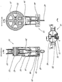
- Figs 1-10 are directed to an embodiment of the sheave 10 having a pulley wheel 20 that rotates on an axle 22.
- the wheel 20 is circular and has a generally "U" shaped profile that cradles a cable 90 that operates on the wheel 20 as shown in the environmental views of Figs. 22 and 23 .
- the axle 22 is attached to a frame that has a top side 30, a latch side 32, and a rigid side 34.
- a locking guard in the form of a cable guard 24 is also attached to the frame and the cable guard 24 has a generally inverted "U" shape that coordinates with the "U" shape of the wheel 20.
- the cable guard 24 meets with the wheel 20 so that there is no gap through which a cable 90 may pass when the cable guard 24 is in a locked or closed position.
- the cable guard 24 operates from a locked or closed position to an unlocked or open position through the operation of a spring bias 26 and a 1/4 turn locking lever 28.
- a spring 26 biases the cable guard 24 in the unlocked or open position when it is not locked down.
- an operator In order to lock the cable guard 24 in the closed or locked position, an operator must press down on the cable guard 24 and actuate the lever 28 to the locked position. To unlock the lever 28, the operator simply moves the lever 28 to the unlocked position.
- the locking lever 28 as shown in Fig. 3 rotates approximately 90 degrees clockwise and 90 degrees counter clockwise.
- the cable guard 24 also operates from a locked or closed position to an unlocked or open position.
- the nut 18 has internal threads which act on and mesh with external threads 16 attached to the frame. As the nut 18 is turned, the cable guard 24 is released and is manually lifted in order to afford access to the wheel 20.
- the latch 40 of the latch side 32 of the frame is hingedly attached to the frame in one embodiment as shown in Figs. 1-10 and 19 .
- the hinged portion 42 of the latch 40 is located at a lower portion of the latch 40 and attaches to a lower portion of the latch side 32 of the frame at a point above the axle's 22 attachment to the frame.
- the latch 40 removably attaches to an upper portion of the latch side 32.
- the attachment uses a plunger 44 in a cavity 46 connection.
- the plunger 44 is cylindrical and is attached to the latch 40.
- the plunger 44 enters a cavity 46 in the latch side 32 of the frame when the latch 40 is in the closed position.
- the plunger 44 includes a spring 48 that biases the plunger 44 in the closed position.
- the plunger 44 has a top lifting tab 50 attached at a point opposite the point of entry into the cavity 46 of the frame.
- the lifting tab 50 is designed so that an operator may lift the plunger 44 out of the cavity 46, thereby countering the spring bias 48, and enable the latch 40 to move from the closed or locked position to an open or unlocked position as shown in Figs. 19 and 20 .
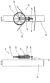
- the latch 40 is not hingedly attached to the latch side 32 of the frame but is, instead, pivotally attached.
- the latch 40 pivots about a pin connection 52 and pivots away from the frame in a direction parallel to the latch side 32 of the frame.
- pivot tab 54 helps to retain the latch against the latch side 32 of the frame in the closed position and also functions as a stop to stop the pivot of the latch 40 beyond a midpoint on the length of the latch side 32 of the frame.
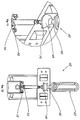
- the invention 10 includes a swivel loop arrangement 60 as highlighted in Figs. 11 and 12 .
- the swivel loop arrangement facilitates the connection of the sheave 10 to a utility pole 92 as shown in Figs 22 and 23 and also the operation of the sheave 10 once connected to the pole 92.
- This connection utilizes a loop 62 and a dome-inside-a-dome swivel 64.
- Figs. 11 and 12 are sectional views that show how the swivel loop 60 is connected to the top 30 of the frame.
- the loop 62 includes a generally "0" shaped loop 60 attached to a cylindrical extension 66.
- the cylindrical extension 66 is molded onto a generally semispherical shaped solid dome 68.
- This solid dome 68 fits within a slightly larger generally semispherical shaped dome cavity 70. Rather than solid, the dome 68 may be hollow with a certain minimum wall thickness. Thus, the frame may rotate 360 degrees around the solid dome 68. Further, the device 10 may pivot and rotate at least 180 degrees via the loop 62 around an attachment point such as a hook 94 fixed to a utility pole 92.
- a hook 94 will be attached to a utility pole 92.
- the loop 62 will be attached to the hook 92.
- An operator will pull up on the tab 50 of the plunger 44 to release the latch 40. Pulling up on the tab 50 will counter the bias spring 48 and pull the plunger 44 out of the cavity 46.
- An operator will unlock the cable guard 24 by rotating the lever 28 and the biasing spring 26 will raise the cable guard 24. Alternatively, the operator will turn the nut 18 to raise the cable guard 24.
- An operator will then load a cable 90 or a mule tape (not shown) attached to cable 90 through the wheel 20. The operator will then press down on the cable guard 24 and then actuate the lever 28 to lock the cable guard 24.
- the operator will actuate the locking nut 18.
- the operator will then push the latch 40 into place and the plunger 44 will engage the plunger cavity 46 by operation of the bias spring 48 of the latch 40.
- the operator may then suspend cable 90 as desired.
- the sheave 10 will pivot 180 degrees about the hook 94 and rotate 360 degrees about the swivel 64.
- the mule tape may be loaded onto the sheave 10 while the latch 40 and the cable guard 24 are in the closed or locked positions.
- the reverse process is employed.
- the operator will unlock the cable guard 24 by rotating the lever 28 or by actuating the locking nut 18.
- the cable guard 24 will rise via the biasing spring 26 or by the threaded connection 16.
- the operator will then release the latch 40 by pulling up on the tab 50 and the latch 40 falling about the hinged connection 42 or about the pivot connection 52.
- the operator will then remove the cable 90 from the sheave 10.
- the frame of the sheave is primarily made of nylon 80.
- the frame may include a steel U-shaped channel 82 which is inset within the nylon 80.
- the steel U-shaped channel 82, or steel insert having another shape, may provide rigidity against bending.
Landscapes
- Physics & Mathematics (AREA)
- Engineering & Computer Science (AREA)
- General Engineering & Computer Science (AREA)
- General Physics & Mathematics (AREA)
- Optics & Photonics (AREA)
- Mechanical Engineering (AREA)
- Pulleys (AREA)
- Clamps And Clips (AREA)
Claims (15)
- Dispositif de réa aérien (10) pour l'installation et la suspension d'un câble (90) comprenant:a. une roue de poulie (20) tournant autour d'un essieu (22) fixé à un cadre ayant un côté rigide (34), un côté supérieur (30) et un côté de verrouillage (32);b. un verrou (40) fixé au côté de verrouillage (32) du cadre pour fournir un accès à la roue (20) du réa, fonctionnant d'une position ouverte à une position fermée, ayant un piston à ressort (44) sollicité dans la position fermée pour fixer le verrou (40) au cadre dans la position fermée;c. un agencement de boucle pivotante (60) comportant une partie de boucle (62) s'étendant au-dessus du côté supérieur (30) du cadre et une partie en dôme plein hémisphérique (68) s'ajustant dans une partie de cavité en dôme hémisphérique (70) du côté supérieur (30) du cadre; etd. une protection de verrouillage (24) fixée de manière fonctionnelle au cadre, fonctionnant d'une position verrouillée à une position déverrouillée, ayant un ressort (26) pour solliciter la protection de verrouillage (24), dans la position déverrouillée et ayant un levier (28) pour verrouiller la protection de verrouillage (24), dans la position verrouillée où un tour du levier (28) dans une première direction déverrouillera la protection de verrouillage (24) et un autre tour du levier (28) dans une direction opposée en combinaison avec une pression appliquée contre le ressort (26) verrouillera la protection de verrouillage (24).
- Dispositif de réa aérien selon la revendication 1, dans lequel le côté de verrouillage (32) peut être situé soit sur le côté gauche soit sur le côté droit du cadre.
- Dispositif de réa aérien selon la revendication 2, dans lequel le verrou (40) est fixé au cadre par l'intermédiaire d'une liaison articulée (42) de sorte que, dans la position ouverte, le verrou (40) pivote vers l'extérieur et loin du côté supérieur (30) du cadre autour de l'articulation (42) vers une extrémité inférieure de la roue de poulie (20).
- Dispositif de réa aérien selon la revendication 2, dans lequel le verrou (40) est fixé au cadre par l'intermédiaire d'une liaison à axe de pivotement (52) de sorte que, dans la position ouverte, le verrou (40) tourne parallèlement au cadre et vers une extrémité inférieure de la roue de poulie (20).
- Dispositif de réa aérien selon la revendication 1, dans lequel la roue de poulie (20) a un profil essentiellement en forme de U et la protection de verrouillage (24) a un profil essentiellement en forme de U inversé qui s'engrène avec le profil en forme de U de la roue de poulie (20) pour former un passage de câble fermé ayant un profil essentiellement en forme de 0 lorsque la protection de verrouillage (24) se trouve dans la position verrouillée.
- Dispositif de réa aérien selon la revendication 5, dans lequel le profil essentiellement en forme de U de la roue de poulie (20) comporte une bride extérieure et le profil essentiellement en forme de U inversé de la protection de verrouillage (24) a une bride intérieure, les brides respectives supportant l'engrènement de la roue de poulie (20) et de la protection de verrouillage (24).
- Dispositif de réa aérien selon la revendication 1, dans lequel le levier (28) de la protection de verrouillage (24) est actionné par un tour de 90 degrés.
- Dispositif de réa aérien selon la revendication 1, dans lequel le levier (28) de la protection de verrouillage (24) est actionné par un tour de 270 degrés ou par une série de tours de 360 degrés.
- Dispositif de réa aérien selon la revendication 1, dans lequel la partie de boucle (62) de l'agencement de boucle pivotante (60) peut être fixée à un pôle fixe (92) et le cadre peut tourner de 360 degrés autour de la partie en dôme plein hémisphérique (68).
- Dispositif de réa aérien selon la revendication 1, dans lequel la roue de poulie (20) et la protection de verrouillage (24) sont réalisées en un matériau non conducteur et dans lequel le cadre est réalisé en nylon (80) et comporte en outre un canal interne non exposé réalisé en acier (82).
- Dispositif de réa aérien (10) selon la revendication 1 dans lequela. ladite roue de poulie (20) a un canal essentiellement en forme de U et une bride extérieure, tournant autour dudit essieu (22) fixé audit cadre ayant ledit côté rigide (34), ledit côté supérieur (30) et ledit côté de verrouillage (32);b. ledit agencement de boucle pivotante (60) comportant ladite partie de boucle (62), pouvant être fixée à un pôle fixe (92); etc. ladite protection de verrouillage (24) a un canal essentiellement en forme de U inversé et une bride intérieure qui s'engrène avec ledit canal essentiellement en forme de U et ladite bride extérieure de ladite roue de poulie (20).
- Dispositif de réa aérien (10) selon la revendication 11, dans lequel le côté de verrouillage (32) peut être situé soit sur le côté gauche soit sur le côté droit du cadre.
- Dispositif de réa aérien selon la revendication 12, dans lequel le verrou (40) est fixé au cadre par l'intermédiaire d'une liaison articulée (42) de sorte que, dans la position ouverte, le verrou (40) pivote vers l'extérieur et loin du côté supérieur (30) du cadre autour de l'articulation (42) vers une extrémité inférieure de la roue de poulie (20).
- Dispositif de réa aérien selon la revendication 12, dans lequel le verrou (40) est fixé au cadre par l'intermédiaire d'une liaison à axe de pivotement (52) de sorte que, dans la position ouverte, le verrou (40) tourne parallèlement au cadre et vers une extrémité inférieure de la roue de poulie (20).
- Dispositif de réa aérien selon la revendication 14, dans lequel le verrou (40) comprend en outre une languette d'arrêt qui fixe le verrou (40) au cadre dans la position fermée et empêche également le verrou (40) de pivoter autour de la broche (52) au-delà de 130 degrés dans les deux directions lorsqu'il est dans la position de fonctionnement.
Applications Claiming Priority (2)
| Application Number | Priority Date | Filing Date | Title |
|---|---|---|---|
| US201261727363P | 2012-11-16 | 2012-11-16 | |
| PCT/US2013/044681 WO2014077901A1 (fr) | 2012-11-16 | 2013-06-07 | Dispositif de réa de câble aérien |
Publications (2)
| Publication Number | Publication Date |
|---|---|
| EP2920633A1 EP2920633A1 (fr) | 2015-09-23 |
| EP2920633B1 true EP2920633B1 (fr) | 2018-03-28 |
Family
ID=48699939
Family Applications (1)
| Application Number | Title | Priority Date | Filing Date |
|---|---|---|---|
| EP13732003.2A Not-in-force EP2920633B1 (fr) | 2012-11-16 | 2013-06-07 | Dispositif de poulie aérienne |
Country Status (4)
| Country | Link |
|---|---|
| US (1) | US9127788B2 (fr) |
| EP (1) | EP2920633B1 (fr) |
| IL (1) | IL238786A (fr) |
| WO (1) | WO2014077901A1 (fr) |
Families Citing this family (21)
| Publication number | Priority date | Publication date | Assignee | Title |
|---|---|---|---|---|
| US10455824B2 (en) * | 2014-11-03 | 2019-10-29 | Rick Eugene LAWRENCE | Agricultural crop application system |
| PT3018777T (pt) * | 2014-11-06 | 2018-01-23 | Rte Reseau De Transp Delectricite | Dispositivo e método de elevação de um cabo montado em postes |
| US9531179B1 (en) * | 2015-09-16 | 2016-12-27 | Jamie Allen Ferguson | Stringer wheel and cable guide apparatus |
| CN106178318A (zh) * | 2016-07-11 | 2016-12-07 | 国网安徽省电力公司培训中心 | 高空作业平行移动防高坠自锁装置 |
| CN106711857B (zh) * | 2017-03-16 | 2018-06-29 | 国家电网公司 | 一种单向防跑线装置 |
| CN106848958A (zh) * | 2017-04-13 | 2017-06-13 | 许陈菲 | 一种电缆孔口保护装置 |
| CN106842468B (zh) * | 2017-04-17 | 2019-04-16 | 张永飞 | 一种挂缆器 |
| US10669136B2 (en) * | 2018-03-07 | 2020-06-02 | Jeffrey Edward Robb | Cable tensioning device |
| CN108383022A (zh) * | 2018-04-04 | 2018-08-10 | 国网安徽省电力有限公司亳州供电公司 | 单相多用滑轮 |
| EP3599685B1 (fr) | 2018-07-27 | 2023-11-15 | Jpf Télébloc Inc. | Poulie de deroulage |
| US11208844B2 (en) * | 2018-08-08 | 2021-12-28 | Mark D. Ross | Ladder roller and pulley system and method of use |
| CN109217180B (zh) * | 2018-10-17 | 2024-03-19 | 北京科技大学 | 用于无人机架线系统的放线滑车 |
| US11324213B2 (en) | 2019-03-07 | 2022-05-10 | Hagie Manufacturing Company | Drop-down applicators for an agricultural sprayer |
| CN112004367A (zh) * | 2020-08-12 | 2020-11-27 | 南阳理工学院 | 一种计算机主机保护装置 |
| FR3116390B1 (fr) * | 2020-11-19 | 2022-09-30 | Rte Reseau De Transp Delectricite | Poulie de déroulage de câble et dispositif d’adaptation pour une telle poulie |
| USD1026629S1 (en) * | 2021-01-28 | 2024-05-14 | Lenny Valdberg | Flared spoke beam wheel assembly for shower door |
| USD1020445S1 (en) * | 2021-01-28 | 2024-04-02 | Lenny Valdberg | Octagonal beam wheel assembly for a shower door |
| CN113335562B (zh) * | 2021-06-15 | 2022-03-22 | 合肥航太电物理技术有限公司 | 一种大型可升降均匀场平板电极系统及其方法 |
| CN113422322B (zh) * | 2021-07-21 | 2022-08-09 | 北京国电天昱建设工程有限公司 | 一种架线滑车及架空线架线方法 |
| CN115367112B (zh) * | 2022-07-11 | 2024-07-02 | 国网河北省电力有限公司衡水供电分公司 | 辅助检修无人机及辅助检修方法 |
| CN117154596B (zh) * | 2023-10-31 | 2024-02-09 | 国网山东省电力公司高青县供电公司 | 杆塔高压线牵拉预紧装置 |
Family Cites Families (26)
| Publication number | Priority date | Publication date | Assignee | Title |
|---|---|---|---|---|
| US516268A (en) * | 1894-03-13 | Snatch-block | ||
| US1878759A (en) * | 1930-08-18 | 1932-09-20 | Copeman Lab Co | Method and apparatus for freezing liquids |
| US2806380A (en) * | 1955-10-24 | 1957-09-17 | L E Myers Co | Sheave block for stringing aluminum cable |
| US3042374A (en) * | 1959-09-22 | 1962-07-03 | Emmett D Livingston | Steel and aluminum pulley block |
| GB951815A (en) | 1961-07-20 | 1964-03-11 | Gerald Alger Monroe Petersen | Open side stringing sheave |
| US4019715A (en) * | 1976-06-09 | 1977-04-26 | Western Electric Company, Inc. | Cable block |
| US4160540A (en) | 1977-12-27 | 1979-07-10 | Lindsey Manufacturing Company | Fast action disconnect for use on a dog nut of a power line insulator and the like |
| FR2533771B1 (fr) | 1982-09-24 | 1985-08-23 | App Auxiliaire Electric | Support de poulie de deroulage pour cable |
| US4687365A (en) | 1985-03-07 | 1987-08-18 | Condux International, Inc. | Load limited swivel connector |
| JPH01308108A (ja) * | 1988-06-04 | 1989-12-12 | Yutaka Consultant:Kk | 電線の延線方法及び延線装置 |
| JPH02133013A (ja) * | 1988-07-26 | 1990-05-22 | Aoki Denki Koji:Kk | 送電線作業用宙乗機 |
| JPH0274109A (ja) * | 1988-09-07 | 1990-03-14 | Sanwa Tekki Corp | 電線の流れ止め型吊り金車 |
| JP2743186B2 (ja) * | 1988-11-30 | 1998-04-22 | 三和テッキ株式会社 | 電線の流れ止め型吊り金車 |
| JPH0697804B2 (ja) * | 1989-03-13 | 1994-11-30 | 株式会社関電工 | 延線工法及びその装置 |
| JPH06106004B2 (ja) * | 1989-03-14 | 1994-12-21 | 株式会社青木電気工事 | 送電線作業用宙乗機 |
| JPH0683532B2 (ja) * | 1989-07-06 | 1994-10-19 | 株式会社安田製作所 | 延線機器及びそれを用いた延線方法 |
| US5735505A (en) | 1995-04-03 | 1998-04-07 | Data Connections, Inc. | Cable pulley device and method |
| US6045124A (en) * | 1995-04-03 | 2000-04-04 | Data Connections, Inc. | Cable pulley device |
| US5618031A (en) | 1995-04-03 | 1997-04-08 | Data Connections, Inc. | Cable pulley device and method |
| GB9724236D0 (en) | 1997-11-18 | 1998-01-14 | Fleury Rejean | Bundle conductor supporting block |
| US5941507A (en) * | 1998-07-02 | 1999-08-24 | Page; Douglas Monroe | Cable installation guide |
| US6375163B1 (en) * | 1999-02-26 | 2002-04-23 | Wireline Technologies, Inc. | Cable stringing block |
| US6517052B1 (en) | 2001-03-29 | 2003-02-11 | Marvin Lake | Installation tool system for pole-mounted communication cables |
| US6666434B2 (en) | 2002-04-01 | 2003-12-23 | Arlen K. Bean | Underground cable retrieval tool |
| US6540207B1 (en) | 2002-04-08 | 2003-04-01 | Harris Manufacturing Inc. | Cable hanging system |
| JP5072571B2 (ja) | 2007-12-19 | 2012-11-14 | 中国電力株式会社 | ケーブル弛み防止吊り車 |
-
2013
- 2013-06-07 US US13/912,506 patent/US9127788B2/en active Active
- 2013-06-07 WO PCT/US2013/044681 patent/WO2014077901A1/fr not_active Ceased
- 2013-06-07 EP EP13732003.2A patent/EP2920633B1/fr not_active Not-in-force
-
2015
- 2015-05-13 IL IL238786A patent/IL238786A/en active IP Right Grant
Also Published As
| Publication number | Publication date |
|---|---|
| US9127788B2 (en) | 2015-09-08 |
| US20140138496A1 (en) | 2014-05-22 |
| WO2014077901A1 (fr) | 2014-05-22 |
| IL238786A (en) | 2016-07-31 |
| IL238786A0 (en) | 2015-06-30 |
| EP2920633A1 (fr) | 2015-09-23 |
Similar Documents
| Publication | Publication Date | Title |
|---|---|---|
| EP2920633B1 (fr) | Dispositif de poulie aérienne | |
| US9738485B1 (en) | Apparatus and method for spooling wire | |
| US10900233B2 (en) | Skylight with manual closing feature | |
| US10995881B2 (en) | Conductor guide system | |
| US20220233891A1 (en) | Rope-Lowering Device and Corresponding Lowering Method | |
| US20250308414A1 (en) | Cross Street Banner Suspension System | |
| US20250316190A1 (en) | Cross Street Banner Suspension System | |
| US6375163B1 (en) | Cable stringing block | |
| EP3911592B1 (fr) | Ensemble de pont roulant | |
| US9676587B1 (en) | Apparatus and method for spooling wire | |
| US7025218B1 (en) | Billboard advertising copy hoist system | |
| US10625975B1 (en) | Apparatus and method for spooling wire | |
| US20170229848A1 (en) | Wire guide assembly | |
| US8789815B2 (en) | Cable hoist and bracket system and method thereof | |
| US20060196988A1 (en) | Vertical cable reel carrier | |
| US9861837B2 (en) | Lift for stealth cell towers | |
| HK1042781A1 (en) | A suspension device having a cable carriage integral therewith | |
| KR101712567B1 (ko) | 샤클 | |
| US20240092616A1 (en) | Hitch mount for hoist | |
| US12560027B2 (en) | Modular ladder for stealth cell towers | |
| CN221607465U (zh) | 一种便于收纳电缆装置 | |
| US20250145405A1 (en) | Dual wire rope motor reel | |
| GB2431779A (en) | Replacing an overhead powerline | |
| AU672898B2 (en) | An apparatus for covering a spa | |
| KR20240018848A (ko) | 바이패스 케이블 주상 설치장치 및 그 설치방법 |
Legal Events
| Date | Code | Title | Description |
|---|---|---|---|
| PUAI | Public reference made under article 153(3) epc to a published international application that has entered the european phase |
Free format text: ORIGINAL CODE: 0009012 |
|
| 17P | Request for examination filed |
Effective date: 20150513 |
|
| AK | Designated contracting states |
Kind code of ref document: A1 Designated state(s): AL AT BE BG CH CY CZ DE DK EE ES FI FR GB GR HR HU IE IS IT LI LT LU LV MC MK MT NL NO PL PT RO RS SE SI SK SM TR |
|
| AX | Request for extension of the european patent |
Extension state: BA ME |
|
| DAX | Request for extension of the european patent (deleted) | ||
| 17Q | First examination report despatched |
Effective date: 20170418 |
|
| GRAP | Despatch of communication of intention to grant a patent |
Free format text: ORIGINAL CODE: EPIDOSNIGR1 |
|
| INTG | Intention to grant announced |
Effective date: 20171030 |
|
| GRAS | Grant fee paid |
Free format text: ORIGINAL CODE: EPIDOSNIGR3 |
|
| GRAA | (expected) grant |
Free format text: ORIGINAL CODE: 0009210 |
|
| AK | Designated contracting states |
Kind code of ref document: B1 Designated state(s): AL AT BE BG CH CY CZ DE DK EE ES FI FR GB GR HR HU IE IS IT LI LT LU LV MC MK MT NL NO PL PT RO RS SE SI SK SM TR |
|
| REG | Reference to a national code |
Ref country code: GB Ref legal event code: FG4D |
|
| REG | Reference to a national code |
Ref country code: CH Ref legal event code: EP |
|
| REG | Reference to a national code |
Ref country code: AT Ref legal event code: REF Ref document number: 983930 Country of ref document: AT Kind code of ref document: T Effective date: 20180415 |
|
| REG | Reference to a national code |
Ref country code: IE Ref legal event code: FG4D |
|
| REG | Reference to a national code |
Ref country code: DE Ref legal event code: R096 Ref document number: 602013035060 Country of ref document: DE |
|
| REG | Reference to a national code |
Ref country code: NL Ref legal event code: FP |
|
| REG | Reference to a national code |
Ref country code: FR Ref legal event code: PLFP Year of fee payment: 6 |
|
| PG25 | Lapsed in a contracting state [announced via postgrant information from national office to epo] |
Ref country code: FI Free format text: LAPSE BECAUSE OF FAILURE TO SUBMIT A TRANSLATION OF THE DESCRIPTION OR TO PAY THE FEE WITHIN THE PRESCRIBED TIME-LIMIT Effective date: 20180328 Ref country code: LT Free format text: LAPSE BECAUSE OF FAILURE TO SUBMIT A TRANSLATION OF THE DESCRIPTION OR TO PAY THE FEE WITHIN THE PRESCRIBED TIME-LIMIT Effective date: 20180328 Ref country code: NO Free format text: LAPSE BECAUSE OF FAILURE TO SUBMIT A TRANSLATION OF THE DESCRIPTION OR TO PAY THE FEE WITHIN THE PRESCRIBED TIME-LIMIT Effective date: 20180628 Ref country code: HR Free format text: LAPSE BECAUSE OF FAILURE TO SUBMIT A TRANSLATION OF THE DESCRIPTION OR TO PAY THE FEE WITHIN THE PRESCRIBED TIME-LIMIT Effective date: 20180328 |
|
| REG | Reference to a national code |
Ref country code: LT Ref legal event code: MG4D |
|
| PG25 | Lapsed in a contracting state [announced via postgrant information from national office to epo] |
Ref country code: BG Free format text: LAPSE BECAUSE OF FAILURE TO SUBMIT A TRANSLATION OF THE DESCRIPTION OR TO PAY THE FEE WITHIN THE PRESCRIBED TIME-LIMIT Effective date: 20180628 Ref country code: RS Free format text: LAPSE BECAUSE OF FAILURE TO SUBMIT A TRANSLATION OF THE DESCRIPTION OR TO PAY THE FEE WITHIN THE PRESCRIBED TIME-LIMIT Effective date: 20180328 Ref country code: GR Free format text: LAPSE BECAUSE OF FAILURE TO SUBMIT A TRANSLATION OF THE DESCRIPTION OR TO PAY THE FEE WITHIN THE PRESCRIBED TIME-LIMIT Effective date: 20180629 Ref country code: SE Free format text: LAPSE BECAUSE OF FAILURE TO SUBMIT A TRANSLATION OF THE DESCRIPTION OR TO PAY THE FEE WITHIN THE PRESCRIBED TIME-LIMIT Effective date: 20180328 Ref country code: LV Free format text: LAPSE BECAUSE OF FAILURE TO SUBMIT A TRANSLATION OF THE DESCRIPTION OR TO PAY THE FEE WITHIN THE PRESCRIBED TIME-LIMIT Effective date: 20180328 |
|
| PG25 | Lapsed in a contracting state [announced via postgrant information from national office to epo] |
Ref country code: RO Free format text: LAPSE BECAUSE OF FAILURE TO SUBMIT A TRANSLATION OF THE DESCRIPTION OR TO PAY THE FEE WITHIN THE PRESCRIBED TIME-LIMIT Effective date: 20180328 Ref country code: EE Free format text: LAPSE BECAUSE OF FAILURE TO SUBMIT A TRANSLATION OF THE DESCRIPTION OR TO PAY THE FEE WITHIN THE PRESCRIBED TIME-LIMIT Effective date: 20180328 Ref country code: PL Free format text: LAPSE BECAUSE OF FAILURE TO SUBMIT A TRANSLATION OF THE DESCRIPTION OR TO PAY THE FEE WITHIN THE PRESCRIBED TIME-LIMIT Effective date: 20180328 Ref country code: ES Free format text: LAPSE BECAUSE OF FAILURE TO SUBMIT A TRANSLATION OF THE DESCRIPTION OR TO PAY THE FEE WITHIN THE PRESCRIBED TIME-LIMIT Effective date: 20180328 Ref country code: AL Free format text: LAPSE BECAUSE OF FAILURE TO SUBMIT A TRANSLATION OF THE DESCRIPTION OR TO PAY THE FEE WITHIN THE PRESCRIBED TIME-LIMIT Effective date: 20180328 Ref country code: IT Free format text: LAPSE BECAUSE OF FAILURE TO SUBMIT A TRANSLATION OF THE DESCRIPTION OR TO PAY THE FEE WITHIN THE PRESCRIBED TIME-LIMIT Effective date: 20180328 |
|
| PG25 | Lapsed in a contracting state [announced via postgrant information from national office to epo] |
Ref country code: SM Free format text: LAPSE BECAUSE OF FAILURE TO SUBMIT A TRANSLATION OF THE DESCRIPTION OR TO PAY THE FEE WITHIN THE PRESCRIBED TIME-LIMIT Effective date: 20180328 Ref country code: SK Free format text: LAPSE BECAUSE OF FAILURE TO SUBMIT A TRANSLATION OF THE DESCRIPTION OR TO PAY THE FEE WITHIN THE PRESCRIBED TIME-LIMIT Effective date: 20180328 Ref country code: CZ Free format text: LAPSE BECAUSE OF FAILURE TO SUBMIT A TRANSLATION OF THE DESCRIPTION OR TO PAY THE FEE WITHIN THE PRESCRIBED TIME-LIMIT Effective date: 20180328 |
|
| REG | Reference to a national code |
Ref country code: AT Ref legal event code: MK05 Ref document number: 983930 Country of ref document: AT Kind code of ref document: T Effective date: 20180328 |
|
| PG25 | Lapsed in a contracting state [announced via postgrant information from national office to epo] |
Ref country code: PT Free format text: LAPSE BECAUSE OF FAILURE TO SUBMIT A TRANSLATION OF THE DESCRIPTION OR TO PAY THE FEE WITHIN THE PRESCRIBED TIME-LIMIT Effective date: 20180730 |
|
| REG | Reference to a national code |
Ref country code: DE Ref legal event code: R097 Ref document number: 602013035060 Country of ref document: DE |
|
| PG25 | Lapsed in a contracting state [announced via postgrant information from national office to epo] |
Ref country code: AT Free format text: LAPSE BECAUSE OF FAILURE TO SUBMIT A TRANSLATION OF THE DESCRIPTION OR TO PAY THE FEE WITHIN THE PRESCRIBED TIME-LIMIT Effective date: 20180328 Ref country code: DK Free format text: LAPSE BECAUSE OF FAILURE TO SUBMIT A TRANSLATION OF THE DESCRIPTION OR TO PAY THE FEE WITHIN THE PRESCRIBED TIME-LIMIT Effective date: 20180328 |
|
| REG | Reference to a national code |
Ref country code: CH Ref legal event code: PL |
|
| PLBE | No opposition filed within time limit |
Free format text: ORIGINAL CODE: 0009261 |
|
| STAA | Information on the status of an ep patent application or granted ep patent |
Free format text: STATUS: NO OPPOSITION FILED WITHIN TIME LIMIT |
|
| 26N | No opposition filed |
Effective date: 20190103 |
|
| REG | Reference to a national code |
Ref country code: BE Ref legal event code: MM Effective date: 20180630 |
|
| REG | Reference to a national code |
Ref country code: IE Ref legal event code: MM4A |
|
| PG25 | Lapsed in a contracting state [announced via postgrant information from national office to epo] |
Ref country code: LU Free format text: LAPSE BECAUSE OF NON-PAYMENT OF DUE FEES Effective date: 20180607 Ref country code: MC Free format text: LAPSE BECAUSE OF FAILURE TO SUBMIT A TRANSLATION OF THE DESCRIPTION OR TO PAY THE FEE WITHIN THE PRESCRIBED TIME-LIMIT Effective date: 20180328 |
|
| PG25 | Lapsed in a contracting state [announced via postgrant information from national office to epo] |
Ref country code: CH Free format text: LAPSE BECAUSE OF NON-PAYMENT OF DUE FEES Effective date: 20180630 Ref country code: IE Free format text: LAPSE BECAUSE OF NON-PAYMENT OF DUE FEES Effective date: 20180607 Ref country code: LI Free format text: LAPSE BECAUSE OF NON-PAYMENT OF DUE FEES Effective date: 20180630 |
|
| PG25 | Lapsed in a contracting state [announced via postgrant information from national office to epo] |
Ref country code: BE Free format text: LAPSE BECAUSE OF NON-PAYMENT OF DUE FEES Effective date: 20180630 Ref country code: SI Free format text: LAPSE BECAUSE OF FAILURE TO SUBMIT A TRANSLATION OF THE DESCRIPTION OR TO PAY THE FEE WITHIN THE PRESCRIBED TIME-LIMIT Effective date: 20180328 |
|
| PGFP | Annual fee paid to national office [announced via postgrant information from national office to epo] |
Ref country code: NL Payment date: 20190626 Year of fee payment: 7 |
|
| PGFP | Annual fee paid to national office [announced via postgrant information from national office to epo] |
Ref country code: FR Payment date: 20190625 Year of fee payment: 7 |
|
| PGFP | Annual fee paid to national office [announced via postgrant information from national office to epo] |
Ref country code: GB Payment date: 20190627 Year of fee payment: 7 Ref country code: DE Payment date: 20190627 Year of fee payment: 7 |
|
| PG25 | Lapsed in a contracting state [announced via postgrant information from national office to epo] |
Ref country code: MT Free format text: LAPSE BECAUSE OF NON-PAYMENT OF DUE FEES Effective date: 20180607 |
|
| PG25 | Lapsed in a contracting state [announced via postgrant information from national office to epo] |
Ref country code: TR Free format text: LAPSE BECAUSE OF FAILURE TO SUBMIT A TRANSLATION OF THE DESCRIPTION OR TO PAY THE FEE WITHIN THE PRESCRIBED TIME-LIMIT Effective date: 20180328 |
|
| PG25 | Lapsed in a contracting state [announced via postgrant information from national office to epo] |
Ref country code: CY Free format text: LAPSE BECAUSE OF FAILURE TO SUBMIT A TRANSLATION OF THE DESCRIPTION OR TO PAY THE FEE WITHIN THE PRESCRIBED TIME-LIMIT Effective date: 20180328 Ref country code: MK Free format text: LAPSE BECAUSE OF NON-PAYMENT OF DUE FEES Effective date: 20180328 Ref country code: HU Free format text: LAPSE BECAUSE OF FAILURE TO SUBMIT A TRANSLATION OF THE DESCRIPTION OR TO PAY THE FEE WITHIN THE PRESCRIBED TIME-LIMIT; INVALID AB INITIO Effective date: 20130607 |
|
| PG25 | Lapsed in a contracting state [announced via postgrant information from national office to epo] |
Ref country code: IS Free format text: LAPSE BECAUSE OF FAILURE TO SUBMIT A TRANSLATION OF THE DESCRIPTION OR TO PAY THE FEE WITHIN THE PRESCRIBED TIME-LIMIT Effective date: 20180728 |
|
| REG | Reference to a national code |
Ref country code: DE Ref legal event code: R119 Ref document number: 602013035060 Country of ref document: DE |
|
| REG | Reference to a national code |
Ref country code: NL Ref legal event code: MM Effective date: 20200701 |
|
| GBPC | Gb: european patent ceased through non-payment of renewal fee |
Effective date: 20200607 |
|
| PG25 | Lapsed in a contracting state [announced via postgrant information from national office to epo] |
Ref country code: FR Free format text: LAPSE BECAUSE OF NON-PAYMENT OF DUE FEES Effective date: 20200630 Ref country code: NL Free format text: LAPSE BECAUSE OF NON-PAYMENT OF DUE FEES Effective date: 20200701 Ref country code: GB Free format text: LAPSE BECAUSE OF NON-PAYMENT OF DUE FEES Effective date: 20200607 |
|
| PG25 | Lapsed in a contracting state [announced via postgrant information from national office to epo] |
Ref country code: DE Free format text: LAPSE BECAUSE OF NON-PAYMENT OF DUE FEES Effective date: 20210101 |
|
| P01 | Opt-out of the competence of the unified patent court (upc) registered |
Effective date: 20230525 |