EP2957652B1 - Appareillage de nitruration pour tôle d'acier électromagnétique orienté et procédé de nitruration - Google Patents
Appareillage de nitruration pour tôle d'acier électromagnétique orienté et procédé de nitruration Download PDFInfo
- Publication number
- EP2957652B1 EP2957652B1 EP14751176.0A EP14751176A EP2957652B1 EP 2957652 B1 EP2957652 B1 EP 2957652B1 EP 14751176 A EP14751176 A EP 14751176A EP 2957652 B1 EP2957652 B1 EP 2957652B1
- Authority
- EP
- European Patent Office
- Prior art keywords
- nitriding
- zone
- strip
- steel sheet
- grain
- Prior art date
- Legal status (The legal status is an assumption and is not a legal conclusion. Google has not performed a legal analysis and makes no representation as to the accuracy of the status listed.)
- Active
Links
Images

Classifications
-
- C—CHEMISTRY; METALLURGY
- C21—METALLURGY OF IRON
- C21D—MODIFYING THE PHYSICAL STRUCTURE OF FERROUS METALS; GENERAL DEVICES FOR HEAT TREATMENT OF FERROUS OR NON-FERROUS METALS OR ALLOYS; MAKING METAL MALLEABLE, e.g. BY DECARBURISATION OR TEMPERING
- C21D8/00—Modifying the physical properties of ferrous metals or ferrous alloys by deformation combined with, or followed by, heat treatment
- C21D8/12—Modifying the physical properties of ferrous metals or ferrous alloys by deformation combined with, or followed by, heat treatment during manufacturing of articles with special electromagnetic properties
- C21D8/1244—Modifying the physical properties of ferrous metals or ferrous alloys by deformation combined with, or followed by, heat treatment during manufacturing of articles with special electromagnetic properties characterised by the heat treatment
- C21D8/1255—Modifying the physical properties of ferrous metals or ferrous alloys by deformation combined with, or followed by, heat treatment during manufacturing of articles with special electromagnetic properties characterised by the heat treatment with diffusion of elements, e.g. decarburising, nitriding
-
- C—CHEMISTRY; METALLURGY
- C21—METALLURGY OF IRON
- C21D—MODIFYING THE PHYSICAL STRUCTURE OF FERROUS METALS; GENERAL DEVICES FOR HEAT TREATMENT OF FERROUS OR NON-FERROUS METALS OR ALLOYS; MAKING METAL MALLEABLE, e.g. BY DECARBURISATION OR TEMPERING
- C21D9/00—Heat treatment, e.g. annealing, hardening, quenching or tempering, adapted for particular articles; Furnaces therefor
- C21D9/46—Heat treatment, e.g. annealing, hardening, quenching or tempering, adapted for particular articles; Furnaces therefor for sheet metals
-
- C—CHEMISTRY; METALLURGY
- C22—METALLURGY; FERROUS OR NON-FERROUS ALLOYS; TREATMENT OF ALLOYS OR NON-FERROUS METALS
- C22C—ALLOYS
- C22C38/00—Ferrous alloys, e.g. steel alloys
- C22C38/02—Ferrous alloys, e.g. steel alloys containing silicon
-
- C—CHEMISTRY; METALLURGY
- C23—COATING METALLIC MATERIAL; COATING MATERIAL WITH METALLIC MATERIAL; CHEMICAL SURFACE TREATMENT; DIFFUSION TREATMENT OF METALLIC MATERIAL; COATING BY VACUUM EVAPORATION, BY SPUTTERING, BY ION IMPLANTATION OR BY CHEMICAL VAPOUR DEPOSITION, IN GENERAL; INHIBITING CORROSION OF METALLIC MATERIAL OR INCRUSTATION IN GENERAL
- C23C—COATING METALLIC MATERIAL; COATING MATERIAL WITH METALLIC MATERIAL; SURFACE TREATMENT OF METALLIC MATERIAL BY DIFFUSION INTO THE SURFACE, BY CHEMICAL CONVERSION OR SUBSTITUTION; COATING BY VACUUM EVAPORATION, BY SPUTTERING, BY ION IMPLANTATION OR BY CHEMICAL VAPOUR DEPOSITION, IN GENERAL
- C23C8/00—Solid state diffusion of only non-metal elements into metallic material surfaces; Chemical surface treatment of metallic material by reaction of the surface with a reactive gas, leaving reaction products of surface material in the coating, e.g. conversion coatings, passivation of metals
- C23C8/02—Pretreatment of the material to be coated
-
- C—CHEMISTRY; METALLURGY
- C23—COATING METALLIC MATERIAL; COATING MATERIAL WITH METALLIC MATERIAL; CHEMICAL SURFACE TREATMENT; DIFFUSION TREATMENT OF METALLIC MATERIAL; COATING BY VACUUM EVAPORATION, BY SPUTTERING, BY ION IMPLANTATION OR BY CHEMICAL VAPOUR DEPOSITION, IN GENERAL; INHIBITING CORROSION OF METALLIC MATERIAL OR INCRUSTATION IN GENERAL
- C23C—COATING METALLIC MATERIAL; COATING MATERIAL WITH METALLIC MATERIAL; SURFACE TREATMENT OF METALLIC MATERIAL BY DIFFUSION INTO THE SURFACE, BY CHEMICAL CONVERSION OR SUBSTITUTION; COATING BY VACUUM EVAPORATION, BY SPUTTERING, BY ION IMPLANTATION OR BY CHEMICAL VAPOUR DEPOSITION, IN GENERAL
- C23C8/00—Solid state diffusion of only non-metal elements into metallic material surfaces; Chemical surface treatment of metallic material by reaction of the surface with a reactive gas, leaving reaction products of surface material in the coating, e.g. conversion coatings, passivation of metals
- C23C8/06—Solid state diffusion of only non-metal elements into metallic material surfaces; Chemical surface treatment of metallic material by reaction of the surface with a reactive gas, leaving reaction products of surface material in the coating, e.g. conversion coatings, passivation of metals using gases
- C23C8/08—Solid state diffusion of only non-metal elements into metallic material surfaces; Chemical surface treatment of metallic material by reaction of the surface with a reactive gas, leaving reaction products of surface material in the coating, e.g. conversion coatings, passivation of metals using gases only one element being applied
- C23C8/24—Nitriding
- C23C8/26—Nitriding of ferrous surfaces
-
- H—ELECTRICITY
- H01—ELECTRIC ELEMENTS
- H01F—MAGNETS; INDUCTANCES; TRANSFORMERS; SELECTION OF MATERIALS FOR THEIR MAGNETIC PROPERTIES
- H01F1/00—Magnets or magnetic bodies characterised by the magnetic materials therefor; Selection of materials for their magnetic properties
- H01F1/01—Magnets or magnetic bodies characterised by the magnetic materials therefor; Selection of materials for their magnetic properties of inorganic materials
- H01F1/03—Magnets or magnetic bodies characterised by the magnetic materials therefor; Selection of materials for their magnetic properties of inorganic materials characterised by their coercivity
- H01F1/12—Magnets or magnetic bodies characterised by the magnetic materials therefor; Selection of materials for their magnetic properties of inorganic materials characterised by their coercivity of soft-magnetic materials
- H01F1/14—Magnets or magnetic bodies characterised by the magnetic materials therefor; Selection of materials for their magnetic properties of inorganic materials characterised by their coercivity of soft-magnetic materials metals or alloys
- H01F1/147—Alloys characterised by their composition
- H01F1/14766—Fe-Si based alloys
- H01F1/14775—Fe-Si based alloys in the form of sheets
-
- H—ELECTRICITY
- H01—ELECTRIC ELEMENTS
- H01F—MAGNETS; INDUCTANCES; TRANSFORMERS; SELECTION OF MATERIALS FOR THEIR MAGNETIC PROPERTIES
- H01F1/00—Magnets or magnetic bodies characterised by the magnetic materials therefor; Selection of materials for their magnetic properties
- H01F1/01—Magnets or magnetic bodies characterised by the magnetic materials therefor; Selection of materials for their magnetic properties of inorganic materials
- H01F1/03—Magnets or magnetic bodies characterised by the magnetic materials therefor; Selection of materials for their magnetic properties of inorganic materials characterised by their coercivity
- H01F1/12—Magnets or magnetic bodies characterised by the magnetic materials therefor; Selection of materials for their magnetic properties of inorganic materials characterised by their coercivity of soft-magnetic materials
- H01F1/14—Magnets or magnetic bodies characterised by the magnetic materials therefor; Selection of materials for their magnetic properties of inorganic materials characterised by their coercivity of soft-magnetic materials metals or alloys
- H01F1/16—Magnets or magnetic bodies characterised by the magnetic materials therefor; Selection of materials for their magnetic properties of inorganic materials characterised by their coercivity of soft-magnetic materials metals or alloys in the form of sheets
-
- C—CHEMISTRY; METALLURGY
- C21—METALLURGY OF IRON
- C21D—MODIFYING THE PHYSICAL STRUCTURE OF FERROUS METALS; GENERAL DEVICES FOR HEAT TREATMENT OF FERROUS OR NON-FERROUS METALS OR ALLOYS; MAKING METAL MALLEABLE, e.g. BY DECARBURISATION OR TEMPERING
- C21D1/00—General methods or devices for heat treatment, e.g. annealing, hardening, quenching or tempering
- C21D1/06—Surface hardening
- C21D1/09—Surface hardening by direct application of electrical or wave energy; by particle radiation
-
- C—CHEMISTRY; METALLURGY
- C21—METALLURGY OF IRON
- C21D—MODIFYING THE PHYSICAL STRUCTURE OF FERROUS METALS; GENERAL DEVICES FOR HEAT TREATMENT OF FERROUS OR NON-FERROUS METALS OR ALLOYS; MAKING METAL MALLEABLE, e.g. BY DECARBURISATION OR TEMPERING
- C21D1/00—General methods or devices for heat treatment, e.g. annealing, hardening, quenching or tempering
- C21D1/74—Methods of treatment in inert gas, controlled atmosphere, vacuum or pulverulent material
- C21D1/773—Methods of treatment in inert gas, controlled atmosphere, vacuum or pulverulent material under reduced pressure or vacuum
-
- C—CHEMISTRY; METALLURGY
- C21—METALLURGY OF IRON
- C21D—MODIFYING THE PHYSICAL STRUCTURE OF FERROUS METALS; GENERAL DEVICES FOR HEAT TREATMENT OF FERROUS OR NON-FERROUS METALS OR ALLOYS; MAKING METAL MALLEABLE, e.g. BY DECARBURISATION OR TEMPERING
- C21D2201/00—Treatment for obtaining particular effects
- C21D2201/05—Grain orientation
-
- C—CHEMISTRY; METALLURGY
- C23—COATING METALLIC MATERIAL; COATING MATERIAL WITH METALLIC MATERIAL; CHEMICAL SURFACE TREATMENT; DIFFUSION TREATMENT OF METALLIC MATERIAL; COATING BY VACUUM EVAPORATION, BY SPUTTERING, BY ION IMPLANTATION OR BY CHEMICAL VAPOUR DEPOSITION, IN GENERAL; INHIBITING CORROSION OF METALLIC MATERIAL OR INCRUSTATION IN GENERAL
- C23C—COATING METALLIC MATERIAL; COATING MATERIAL WITH METALLIC MATERIAL; SURFACE TREATMENT OF METALLIC MATERIAL BY DIFFUSION INTO THE SURFACE, BY CHEMICAL CONVERSION OR SUBSTITUTION; COATING BY VACUUM EVAPORATION, BY SPUTTERING, BY ION IMPLANTATION OR BY CHEMICAL VAPOUR DEPOSITION, IN GENERAL
- C23C14/00—Coating by vacuum evaporation, by sputtering or by ion implantation of the coating forming material
- C23C14/06—Coating by vacuum evaporation, by sputtering or by ion implantation of the coating forming material characterised by the coating material
-
- C—CHEMISTRY; METALLURGY
- C23—COATING METALLIC MATERIAL; COATING MATERIAL WITH METALLIC MATERIAL; CHEMICAL SURFACE TREATMENT; DIFFUSION TREATMENT OF METALLIC MATERIAL; COATING BY VACUUM EVAPORATION, BY SPUTTERING, BY ION IMPLANTATION OR BY CHEMICAL VAPOUR DEPOSITION, IN GENERAL; INHIBITING CORROSION OF METALLIC MATERIAL OR INCRUSTATION IN GENERAL
- C23C—COATING METALLIC MATERIAL; COATING MATERIAL WITH METALLIC MATERIAL; SURFACE TREATMENT OF METALLIC MATERIAL BY DIFFUSION INTO THE SURFACE, BY CHEMICAL CONVERSION OR SUBSTITUTION; COATING BY VACUUM EVAPORATION, BY SPUTTERING, BY ION IMPLANTATION OR BY CHEMICAL VAPOUR DEPOSITION, IN GENERAL
- C23C14/00—Coating by vacuum evaporation, by sputtering or by ion implantation of the coating forming material
- C23C14/22—Coating by vacuum evaporation, by sputtering or by ion implantation of the coating forming material characterised by the process of coating
- C23C14/24—Vacuum evaporation
-
- C—CHEMISTRY; METALLURGY
- C23—COATING METALLIC MATERIAL; COATING MATERIAL WITH METALLIC MATERIAL; CHEMICAL SURFACE TREATMENT; DIFFUSION TREATMENT OF METALLIC MATERIAL; COATING BY VACUUM EVAPORATION, BY SPUTTERING, BY ION IMPLANTATION OR BY CHEMICAL VAPOUR DEPOSITION, IN GENERAL; INHIBITING CORROSION OF METALLIC MATERIAL OR INCRUSTATION IN GENERAL
- C23C—COATING METALLIC MATERIAL; COATING MATERIAL WITH METALLIC MATERIAL; SURFACE TREATMENT OF METALLIC MATERIAL BY DIFFUSION INTO THE SURFACE, BY CHEMICAL CONVERSION OR SUBSTITUTION; COATING BY VACUUM EVAPORATION, BY SPUTTERING, BY ION IMPLANTATION OR BY CHEMICAL VAPOUR DEPOSITION, IN GENERAL
- C23C14/00—Coating by vacuum evaporation, by sputtering or by ion implantation of the coating forming material
- C23C14/22—Coating by vacuum evaporation, by sputtering or by ion implantation of the coating forming material characterised by the process of coating
- C23C14/56—Apparatus specially adapted for continuous coating; Arrangements for maintaining the vacuum, e.g. vacuum locks
- C23C14/562—Apparatus specially adapted for continuous coating; Arrangements for maintaining the vacuum, e.g. vacuum locks for coating elongated substrates
-
- C—CHEMISTRY; METALLURGY
- C23—COATING METALLIC MATERIAL; COATING MATERIAL WITH METALLIC MATERIAL; CHEMICAL SURFACE TREATMENT; DIFFUSION TREATMENT OF METALLIC MATERIAL; COATING BY VACUUM EVAPORATION, BY SPUTTERING, BY ION IMPLANTATION OR BY CHEMICAL VAPOUR DEPOSITION, IN GENERAL; INHIBITING CORROSION OF METALLIC MATERIAL OR INCRUSTATION IN GENERAL
- C23C—COATING METALLIC MATERIAL; COATING MATERIAL WITH METALLIC MATERIAL; SURFACE TREATMENT OF METALLIC MATERIAL BY DIFFUSION INTO THE SURFACE, BY CHEMICAL CONVERSION OR SUBSTITUTION; COATING BY VACUUM EVAPORATION, BY SPUTTERING, BY ION IMPLANTATION OR BY CHEMICAL VAPOUR DEPOSITION, IN GENERAL
- C23C8/00—Solid state diffusion of only non-metal elements into metallic material surfaces; Chemical surface treatment of metallic material by reaction of the surface with a reactive gas, leaving reaction products of surface material in the coating, e.g. conversion coatings, passivation of metals
- C23C8/06—Solid state diffusion of only non-metal elements into metallic material surfaces; Chemical surface treatment of metallic material by reaction of the surface with a reactive gas, leaving reaction products of surface material in the coating, e.g. conversion coatings, passivation of metals using gases
- C23C8/36—Solid state diffusion of only non-metal elements into metallic material surfaces; Chemical surface treatment of metallic material by reaction of the surface with a reactive gas, leaving reaction products of surface material in the coating, e.g. conversion coatings, passivation of metals using gases using ionised gases, e.g. ionitriding
- C23C8/38—Treatment of ferrous surfaces
Definitions
- the disclosure relates to an apparatus and a method that are suitable for nitriding a grain-oriented electrical steel sheet.
- a grain oriented electrical steel sheet is a soft magnetic material used as an iron core material of transformers and generators, and is required to have excellent magnetic properties, in particular low iron loss.
- This steel sheet has a texture in which the ⁇ 001> direction, which is an easy magnetization axis of iron, is highly accorded with the rolling direction of the steel sheet.
- Such texture is formed through the so-called secondary recrystallization where crystal grains with (110)[001] orientation referred to as Goss orientation are preferentially grown massively, during secondary recrystallization annealing in the production process of the grain-oriented electrical steel sheet.
- such grain-oriented electrical steel sheets have been manufactured by heating a slab containing 4.5 mass% or less of Si and inhibitor components such as MnS, MnSe and AlN to 1300 °C or higher, thereby dissolving the inhibitor components, then subjecting the slab to hot rolling to obtain a hot rolled steel sheet, and then subjecting the hot rolled steel sheet to hot band annealing as necessary, and subsequent cold rolling once, or twice or more with intermediate annealing performed therebetween until reaching final sheet thickness, then subjecting the steel sheet to primary recrystallization annealing in wet hydrogen atmosphere to perform primary recrystallization and decarburization, and then applying thereon an annealing separator mainly composed of magnesia (MgO) and performing final annealing at 1200 °C for around 5 hours for secondary recrystallization and purification of inhibitor components (e.g. see US1965559A (PTL 1), JPS4015644B (PTL 2) and JPS5113469B (PTL 3)).
- MgO
- JP H08 158 038 A discloses a plasma treating device wherein a hearth roll for supporting a strip continuously supplied into a carburization furnace is grounded and used as a main cathode, and a low-temp. plasma electrode pair is formed with the auxiliary cathodes parallel to both faces of the strip and the anodes opposed to and parallel with both side edges of the strip in the width direction and vertical to the strip face.
- the furnace is reduced to a specified pressure by the pressure reducing band set on the inlet and outlet sides of the furnace, the carburizing gas and a voltage to be impressed on the anodes are variably controlled, and the strip is carburized with the continuous low-temperature plasma.
- a strip temperature adjusting band and a cooling band are arranged on the outlet side of the carburization furnace to control the diffusion rate of the solid-soln.
- JP H04 136154 A discloses a plasma treating device wherein a thin steel strip traveling in the regulated moving line is grounded and electrodes are installed on both sides above and below this moving line in a plasma treating chamber.
- Plasma generating means are respectively provided on the outer side of the respective electrodes.
- Each of the plasma generating means is constituted of a filament, an anode electrode plate having plural holes and a cathode electrode plate having plural holes.
- a gaseous mixture composed N2 and H2 is introduced into this plasma generating means and is brought into collision against thermions, by which the gases are ionized and are converted to plasma. N ions are sticked to the thin steel strip by arc-discharging between the electrodes and the thin steel strip.
- the electrodes maintained at a positive potential are disposed to face the moving line at this time and, therefore, the thin steel strip is maintained at the negative potential relative to the electrodes even when the strip is grounded.
- the steel strip is thus subjected to the safe plasma treatment by the generated plasma.
- JP H02 213460 A discloses a continuous heat-treating device for a steel sheet formed by a heating zone, a soaking zone, a cooling zone, a plasma treating zone and a cooling zone.
- the band steel is heated to a high temp. in the heating zone and the soaking zone, and a gas jet is blown against the heated sheet in the cooling zone to quench the sheet to 300-700 degrees C.
- the band steel is then treated with plasma in the plasma treating zone and then cooled in the cooling zone.
- a differential-pressure sealing device is provided in the inlet and outlet sides of the sheet in the plasma treating zone, and a plasma treating device to be evacuated from the atmospheric pressure to about 10 -2 -10Torr in several stages is provided.
- US 6 361 628 B1 discloses a method for making a composite metal product by adding at least one substance to said product, which consists in using a metal product in the form of a continuous strip moved in a vacuum chamber, applying the substance on said strip and diffusing said substance at least partially into the strip when it is passing in the vacuum chamber maintaining it at a temperature lower than its melting point, but sufficiently high for enabling said diffusion.
- US 2005/112377 A1 discloses a grain-oriented magnetic steel sheet comprising an electrically insulating coating, made of an amorphous carbon-hydrogen network, which is applied after final annealing in order to ensure electrical insulation of the individual layers of sheet, said grain-oriented magnetic steel sheet being used e.g. in transformers.
- a method for producing the grain-oriented magnetic steel sheet comprising an electrically insulating coating made of an amorphous carbon-hydrogen network is disclosed, which method consists of coating of the strip-shaped sheet substrate taking place in a continuous strip method.
- the techniques disclosed in PTLs 5 to 7 are methods of performing nitriding by spraying nitriding gas on the steel sheet. Therefore, non-uniformity of the furnace temperature in terms of duration and position, and difference in decomposition amount of nitriding gas in pipes caused by heat could cause a difference in nitrogen increase depending on the area of the strip, and as a result, secondary recrystallization could become non-uniform and lead to deterioration of magnetic properties.
- the nitriding zone is provided with glow discharge electrodes, and the strip is subjected to plasma nitriding by glow discharge with the glow discharge electrodes functioning as positive electrodes and the strip functioning as a negative electrode.
- An apparatus for nitriding a grain-oriented electrical steel sheet according to the present invention is defined by the combination of features of claim 1.
- Dependent claims relate to preferred embodiments.
- a method according to the present invention is defined by the combination of features of claim 7.
- nitrogen gas can be used as a nitrogen source, and therefore nitrogen sources which may cause environmental problems such as ammonia required for performing gas nitriding, cyan salt required for performing salt bath nitriding or the like do not have to be used. For these reasons, our method has a significant industrial usefulness.
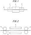
- FIG. 1 schematically shows a preferable example of the nitriding apparatus of the disclosure.
- a heating zone is labeled 1
- a nitriding zone is labeled 2
- a cooling zone is labeled 3.
- a strip continuously passing inside the nitriding apparatus with a structure comprising the aforementioned components is labeled 4.
- the heating zone may be provided when required and is not always necessary.
- a strip 4 is subjected to plasma nitriding by glow discharge in the above nitriding zone 2.
- FIG. 2 shows a preferable example of a plasma nitriding device according to the disclosure.
- glow discharge electrodes are labeled 5
- pinch rolls which also serve as electrode rolls are labeled 6
- glow discharge electrodes 5 are disposed above and below the strip 4.
- the inside of the nitriding zone 2 is filled with nitrogen gas and hydrogen gas as nitrogen sources.
- glow discharge electrodes 5 functioning as positive electrodes and the strip 4 functioning as a negative electrode
- voltage is applied between the electrodes via pinch rolls (electrode rolls) to generate glow discharge on both sides of the strip 4, to subject both sides of the strip 4 to nitriding at the same time in plasma atmosphere.
- FIG. 3 shows another example of a plasma nitriding device according to the disclosure.
- glow discharge is generated with a strip 4 arranged to be along electrode rolls 6' disposed opposite to positive electrodes (glow discharge electrodes) 5.
- nitriding is performed on only one side of the strip 4. Therefore, in order to perform nitriding on both sides of the strip 4, another nitriding device will be required.
- the strip is preferably heated to a temperature of 400 °C or higher.
- the inside of the nitriding zone is preferably kept under a reduced pressure.
- heating zone and the cooling zone have a lower degree of pressure reduction compared to the nitriding zone, it is preferable for them to be kept in a state with reduced pressure compared to atmospheric pressure, and by doing so, heat exchange due to convection tends to proceed, and heating and cooling efficiency can be improved.
- the inside of the nitriding zone is preferably depressurized to around 0.5 torr to 10 torr which is a preferable glow discharge condition, and the heating zone and the cooling zone are preferably depressurized, with a lower degree of pressure reduction, to around 30 torr to 500 torr.
- FIG. 4 shows an upstream atmosphere adjusting zone 7-1 and a downstream atmosphere adjusting zone 7-2 with a nitriding zone 2 in between.
- each of the upstream atmosphere adjusting zone 7-1 and the downstream atmosphere adjusting zone 7-2 is preferably divided into multiple air chambers where the degrees of pressure reduction are individually adjustable.
- the degrees of pressure reduction of the air chambers in the upstream atmosphere adjusting zone 7-1 are gradually increased toward the nitriding zone 2, while the degree of pressure reduction of the air chambers in the downstream atmosphere adjusting zone 7-2 are gradually decreased from the nitriding zone 2 toward the cooling zone 3.
- the inside of the nitriding zone is divided into multiple zones in the width direction of the strip where nitriding can be performed individually inside each divided zone.
- the heating zone can be omitted if it is disposed in a continuous line for performing other necessary treatment and the strip is already heated, or if the heating by plasma irradiation at the time of plasma nitriding is sufficient.
- the cooling zone may be disposed after the zone for such treatment.
- nitriding apparatus may be an independent apparatus that continuously performs only nitriding, or be attached to a processing line for performing another treatment, and in the case of a continuous line, it may be attached to the optimal place considering conditions including efficiency.
- the strip which is the material to be treated is not particularly limited and, as long as it is a grain-oriented electrical steel strip, any conventionally known strip is applicable.
Landscapes
- Chemical & Material Sciences (AREA)
- Engineering & Computer Science (AREA)
- Materials Engineering (AREA)
- Mechanical Engineering (AREA)
- Metallurgy (AREA)
- Organic Chemistry (AREA)
- Physics & Mathematics (AREA)
- Thermal Sciences (AREA)
- Crystallography & Structural Chemistry (AREA)
- Chemical Kinetics & Catalysis (AREA)
- Electromagnetism (AREA)
- Manufacturing & Machinery (AREA)
- Dispersion Chemistry (AREA)
- Power Engineering (AREA)
- Manufacturing Of Steel Electrode Plates (AREA)
- Soft Magnetic Materials (AREA)
- Solid-Phase Diffusion Into Metallic Material Surfaces (AREA)
Claims (7)
- Appareil de nitruration d'une tôle d'acier électrique à grains orientés pour une nitruration de manière continue d'une bande qui est alimentée de manière continue après laminage à froid et avant un recuit de recristallisation secondaire dans une ligne de production d'une tôle d'acier électrique à grains orientés, comprenant :une zone de nitruration (2) pour la nitruration de la bande ; etune zone de refroidissement (3) pour refroidir la bande ;dans lequel la zone de nitruration (2) est pourvue d'électrodes à décharge luminescente (5), l'appareil est configuré pour soumettre la bande à une nitruration à plasma par décharge luminescente, les électrodes à décharge luminescente (5) fonctionnant comme des électrodes positives et la bande fonctionnant comme une électrode négative, etcaractérisé en ce que l'intérieur de la zone de nitruration (2) est divisé en de multiples zones dans la direction de largeur de la bande pour permettre des contrôles individuels de nitruration à l'intérieur de chaque zone divisée.
- Appareil de nitruration d'une tôle d'acier électrique à grains orientés selon la revendication 1, dans lequel l'appareil est configuré pour maintenir la zone de nitruration (2) sous une pression réduite.
- Appareil de nitruration d'une tôle d'acier électrique à grains orientés selon la revendication 2, comprenant en outre :une zone de chauffage (1) pourvue en amont de la zone de nitruration (2) pour chauffer la bande, dans lequel l'appareil est configuré pour maintenir au moins une de la zone de chauffage (1) et de la zone de refroidissement (3) dans un état ayant un degré de réduction de pression plus faible par rapport à la zone de nitruration (2) et une pression réduite par rapport à la pression atmosphérique.
- Appareil de nitruration d'une tôle d'acier électrique à grains orientés selon la revendication 3, comprenant en outre une zone d'ajustement d'atmosphère amont (7-1) pourvue entre la zone de chauffage (1) et la zone de nitruration (2), et une zone d'ajustement d'atmosphère aval (7-2) pourvue entre la zone de nitruration (2) et la zone de refroidissement (3).
- Appareil de nitruration d'une tôle d'acier électrique à grains orientés selon la revendication 4, dans lequel la zone d'ajustement d'atmosphère amont (7-1) et la zone d'ajustement d'atmosphère aval (7-2) sont chacune divisées en de multiples chambres à air où les degrés de réduction de pression sont ajustables individuellement.
- Appareil de nitruration d'une tôle d'acier électrique à grains orientés selon la revendication 5,
dans lequel l'appareil est configuré pour augmenter graduellement les degrés de réduction de pression dans les chambres à air dans la zone d'ajustement d'atmosphère amont (7-1) en direction de la zone de nitruration (2), pendant que l'appareil est configuré pour diminuer graduellement le degré de réduction de pression des chambres à air dans la zone d'ajustement d'atmosphère aval (7-2) en direction de la zone de refroidissement (3). - Procédé de nitruration d'une tôle d'acier électrique à grains orientés comprenant une nitruration à plasma de la bande par décharge luminescente à l'aide de l'appareil selon l'une quelconque des revendications 1 à 6 après laminage à froid et avant un recuit de recristallisation secondaire pendant la production d'une tôle d'acier électrique à grains orientés.
Applications Claiming Priority (2)
| Application Number | Priority Date | Filing Date | Title |
|---|---|---|---|
| JP2013029368A JP5942886B2 (ja) | 2013-02-18 | 2013-02-18 | 方向性電磁鋼板の窒化処理設備および窒化処理方法 |
| PCT/JP2014/000820 WO2014125841A1 (fr) | 2013-02-18 | 2014-02-18 | Appareillage de nitruration pour tôle d'acier électromagnétique orienté et procédé de nitruration |
Publications (3)
| Publication Number | Publication Date |
|---|---|
| EP2957652A1 EP2957652A1 (fr) | 2015-12-23 |
| EP2957652A4 EP2957652A4 (fr) | 2016-03-02 |
| EP2957652B1 true EP2957652B1 (fr) | 2017-11-01 |
Family
ID=51353852
Family Applications (1)
| Application Number | Title | Priority Date | Filing Date |
|---|---|---|---|
| EP14751176.0A Active EP2957652B1 (fr) | 2013-02-18 | 2014-02-18 | Appareillage de nitruration pour tôle d'acier électromagnétique orienté et procédé de nitruration |
Country Status (7)
| Country | Link |
|---|---|
| US (1) | US10066286B2 (fr) |
| EP (1) | EP2957652B1 (fr) |
| JP (1) | JP5942886B2 (fr) |
| KR (1) | KR20150108386A (fr) |
| CN (1) | CN105074044B (fr) |
| RU (1) | RU2615752C2 (fr) |
| WO (1) | WO2014125841A1 (fr) |
Families Citing this family (7)
| Publication number | Priority date | Publication date | Assignee | Title |
|---|---|---|---|---|
| JP5942884B2 (ja) | 2013-02-18 | 2016-06-29 | Jfeスチール株式会社 | 方向性電磁鋼板の窒化処理設備および窒化処理方法 |
| JP5942886B2 (ja) | 2013-02-18 | 2016-06-29 | Jfeスチール株式会社 | 方向性電磁鋼板の窒化処理設備および窒化処理方法 |
| CN104831040B (zh) * | 2015-05-25 | 2017-11-03 | 马钢(集团)控股有限公司 | 一种电工钢退火加热装置及其退火加热方法 |
| RU2654161C1 (ru) * | 2017-02-27 | 2018-05-16 | федеральное государственное бюджетное образовательное учреждение высшего образования "Уфимский государственный авиационный технический университет" | Способ локального ионного азотирования стальных изделий в тлеющем разряде с магнитным полем |
| CN110402007B (zh) * | 2019-07-31 | 2021-10-01 | 北京交通大学 | 一种基于空气辉光放电等离子体的材料表面处理装置 |
| CN111321369A (zh) * | 2020-03-05 | 2020-06-23 | 马鞍山钢铁股份有限公司 | 用于取向硅钢生产的离子氮化装置及其离子氮化方法 |
| CN117248176B (zh) * | 2023-10-20 | 2025-11-18 | 钢铁研究总院有限公司 | 一种板带在线连续渗氮装置 |
Family Cites Families (27)
| Publication number | Priority date | Publication date | Assignee | Title |
|---|---|---|---|---|
| US588314A (en) * | 1897-08-17 | Nut-lock | ||
| US1965559A (en) | 1933-08-07 | 1934-07-03 | Cold Metal Process Co | Electrical sheet and method and apparatus for its manufacture and test |
| DE1252220B (fr) | 1963-04-05 | 1968-04-25 | ||
| JPS5113469B2 (fr) | 1972-10-13 | 1976-04-28 | ||
| US4109157A (en) * | 1975-12-18 | 1978-08-22 | Kawasaki Jukogyo Kabushiki Kaisha | Apparatus for ion-nitriding |
| DE2811942C2 (de) * | 1977-03-23 | 1986-09-18 | Vide et Traitement S.A., Neuilly-en-Thelle | Ofen zur ionischen Nitrierbehandlung von metallischen Werkstücken |
| JPH02213460A (ja) * | 1989-02-15 | 1990-08-24 | Sumitomo Metal Ind Ltd | 表面特性の優れた鋼板の連続製造法と装置 |
| JPH03122227A (ja) | 1989-10-05 | 1991-05-24 | Nippon Steel Corp | 方向性電磁鋼板の脱炭連続焼鈍炉 |
| JP2771634B2 (ja) | 1989-10-05 | 1998-07-02 | 新日本製鐵株式会社 | 方向性電磁鋼板の脱炭連続焼鈍炉 |
| JPH0733549B2 (ja) * | 1990-04-21 | 1995-04-12 | 新日本製鐵株式会社 | 二方向性珪素鋼板の製造方法 |
| JPH04131376A (ja) * | 1990-09-21 | 1992-05-06 | Kawasaki Steel Corp | 差圧シール装置 |
| JPH04136154A (ja) * | 1990-09-28 | 1992-05-11 | Sumitomo Heavy Ind Ltd | プラズマ処理装置 |
| JPH04198468A (ja) | 1990-11-29 | 1992-07-17 | Nkk Corp | 帯板の連続前処理装置 |
| JPH083125B2 (ja) * | 1991-01-08 | 1996-01-17 | 新日本製鐵株式会社 | 磁束密度の高い方向性電磁鋼板の製造方法 |
| JP3014603B2 (ja) * | 1994-11-29 | 2000-02-28 | 川崎製鉄株式会社 | 金属帯の連続プラズマ処理装置 |
| US5643370A (en) * | 1995-05-16 | 1997-07-01 | Armco Inc. | Grain oriented electrical steel having high volume resistivity and method for producing same |
| JP3940205B2 (ja) | 1997-06-30 | 2007-07-04 | 新日本製鐵株式会社 | 長手・幅方向偏差に小さい方向性電磁鋼板の窒化処理方法とそのための装置 |
| EP0909832A1 (fr) * | 1997-10-17 | 1999-04-21 | RECHERCHE ET DEVELOPPEMENT DU GROUPE COCKERILL SAMBRE, en abrégé: RD-CS | Procédé pour la mise à composition d'un produit métallique |
| IT1316029B1 (it) * | 2000-12-18 | 2003-03-26 | Acciai Speciali Terni Spa | Processo per la produzione di acciaio magnetico a grano orientato. |
| DE10130308B4 (de) * | 2001-06-22 | 2005-05-12 | Thyssenkrupp Electrical Steel Ebg Gmbh | Kornorientiertes Elektroblech mit einer elektrisch isolierenden Beschichtung |
| JP4321120B2 (ja) | 2003-05-29 | 2009-08-26 | Jfeスチール株式会社 | 磁気特性に優れた方向性電磁鋼板の製造方法 |
| JP4015644B2 (ja) | 2004-05-31 | 2007-11-28 | 株式会社ソニー・コンピュータエンタテインメント | 画像処理装置及び画像処理方法 |
| JP5113469B2 (ja) | 2006-09-29 | 2013-01-09 | 日本タングステン株式会社 | 炭化物粉末被覆酸化物粉末の製造方法 |
| RU2413033C2 (ru) * | 2009-01-11 | 2011-02-27 | Государственное учреждение Институт электрофизики Уральского отделения Российской академии наук | Способ плазменного азотирования изделия из стали или из цветного сплава |
| CN102650014B (zh) * | 2011-02-28 | 2014-08-13 | 新日铁住金株式会社 | 方向性电磁钢板的制造方法 |
| JP5942886B2 (ja) | 2013-02-18 | 2016-06-29 | Jfeスチール株式会社 | 方向性電磁鋼板の窒化処理設備および窒化処理方法 |
| US20140326182A1 (en) | 2013-05-03 | 2014-11-06 | Areesys Corporation | Continuous Substrate Processing Apparatus |
-
2013
- 2013-02-18 JP JP2013029368A patent/JP5942886B2/ja active Active
-
2014
- 2014-02-18 CN CN201480009247.8A patent/CN105074044B/zh active Active
- 2014-02-18 EP EP14751176.0A patent/EP2957652B1/fr active Active
- 2014-02-18 US US14/761,707 patent/US10066286B2/en active Active
- 2014-02-18 RU RU2015139697A patent/RU2615752C2/ru active
- 2014-02-18 KR KR1020157021977A patent/KR20150108386A/ko not_active Ceased
- 2014-02-18 WO PCT/JP2014/000820 patent/WO2014125841A1/fr not_active Ceased
Non-Patent Citations (1)
| Title |
|---|
| None * |
Also Published As
| Publication number | Publication date |
|---|---|
| JP5942886B2 (ja) | 2016-06-29 |
| WO2014125841A1 (fr) | 2014-08-21 |
| US20150361544A1 (en) | 2015-12-17 |
| WO2014125841A8 (fr) | 2015-08-06 |
| KR20150108386A (ko) | 2015-09-25 |
| CN105074044B (zh) | 2017-07-28 |
| EP2957652A1 (fr) | 2015-12-23 |
| RU2015139697A (ru) | 2017-03-23 |
| RU2615752C2 (ru) | 2017-04-11 |
| US10066286B2 (en) | 2018-09-04 |
| CN105074044A (zh) | 2015-11-18 |
| EP2957652A4 (fr) | 2016-03-02 |
| JP2014156646A (ja) | 2014-08-28 |
Similar Documents
| Publication | Publication Date | Title |
|---|---|---|
| EP2957652B1 (fr) | Appareillage de nitruration pour tôle d'acier électromagnétique orienté et procédé de nitruration | |
| US11198917B2 (en) | Method for nitriding grain-oriented electrical steel sheet | |
| CN105008555B (zh) | 方向性电磁钢板的制造方法 | |
| JP6252833B2 (ja) | マルテンサイト系ステンレス鋼鋼帯の製造方法 | |
| US9666350B2 (en) | Ultrathin electromagnetic steel sheet | |
| CN101294268A (zh) | 一种取向硅钢的渗氮方法 | |
| JP3940205B2 (ja) | 長手・幅方向偏差に小さい方向性電磁鋼板の窒化処理方法とそのための装置 | |
| US10214793B2 (en) | Method and device for nitriding grain-oriented electrical steel sheet | |
| KR102496043B1 (ko) | 타깃 교환 장치 및 표면 처리 설비 | |
| JP6137490B2 (ja) | 一次再結晶集合組織の予測方法および方向性電磁鋼板の製造方法 | |
| ITRM20000451A1 (it) | Procedimento per la regolazione della distribuzione degli inibitori nella produzione di lamierini magnetici a grano orientato. | |
| JP6094504B2 (ja) | 方向性電磁鋼板の竪型窒化処理設備および窒化処理方法 | |
| JP2771633B2 (ja) | 方向性電磁鋼板の脱炭連続焼鈍装置 | |
| JP5942885B2 (ja) | 方向性電磁鋼板の窒化処理方法および窒化処理装置 | |
| JPH04326A (ja) | 方向性けい素鋼板の鉄損低減用連続処理装置 | |
| JP2012087354A (ja) | 方向性電磁鋼板の仕上焼鈍方法および仕上焼鈍設備 | |
| JPH05302124A (ja) | 歪取り焼鈍を施しても特性の劣化しない低鉄損一方向性珪素鋼板の製造装置 | |
| JP2004197154A (ja) | 一方向性珪素鋼板およびその製造方法ならびにセラミック被膜の被覆装置 | |
| JPH0230758A (ja) | 差圧シール装置 |
Legal Events
| Date | Code | Title | Description |
|---|---|---|---|
| PUAI | Public reference made under article 153(3) epc to a published international application that has entered the european phase |
Free format text: ORIGINAL CODE: 0009012 |
|
| 17P | Request for examination filed |
Effective date: 20150807 |
|
| AK | Designated contracting states |
Kind code of ref document: A1 Designated state(s): AL AT BE BG CH CY CZ DE DK EE ES FI FR GB GR HR HU IE IS IT LI LT LU LV MC MK MT NL NO PL PT RO RS SE SI SK SM TR |
|
| AX | Request for extension of the european patent |
Extension state: BA ME |
|
| A4 | Supplementary search report drawn up and despatched |
Effective date: 20160201 |
|
| RIC1 | Information provided on ipc code assigned before grant |
Ipc: C21D 9/46 20060101ALI20160126BHEP Ipc: C23C 8/38 20060101AFI20160126BHEP Ipc: C21D 8/12 20060101ALI20160126BHEP Ipc: H01F 1/16 20060101ALI20160126BHEP |
|
| DAX | Request for extension of the european patent (deleted) | ||
| GRAP | Despatch of communication of intention to grant a patent |
Free format text: ORIGINAL CODE: EPIDOSNIGR1 |
|
| STAA | Information on the status of an ep patent application or granted ep patent |
Free format text: STATUS: GRANT OF PATENT IS INTENDED |
|
| INTG | Intention to grant announced |
Effective date: 20170621 |
|
| GRAS | Grant fee paid |
Free format text: ORIGINAL CODE: EPIDOSNIGR3 |
|
| GRAA | (expected) grant |
Free format text: ORIGINAL CODE: 0009210 |
|
| STAA | Information on the status of an ep patent application or granted ep patent |
Free format text: STATUS: THE PATENT HAS BEEN GRANTED |
|
| AK | Designated contracting states |
Kind code of ref document: B1 Designated state(s): AL AT BE BG CH CY CZ DE DK EE ES FI FR GB GR HR HU IE IS IT LI LT LU LV MC MK MT NL NO PL PT RO RS SE SI SK SM TR |
|
| REG | Reference to a national code |
Ref country code: GB Ref legal event code: FG4D |
|
| REG | Reference to a national code |
Ref country code: CH Ref legal event code: EP Ref country code: AT Ref legal event code: REF Ref document number: 942116 Country of ref document: AT Kind code of ref document: T Effective date: 20171115 |
|
| REG | Reference to a national code |
Ref country code: IE Ref legal event code: FG4D |
|
| REG | Reference to a national code |
Ref country code: DE Ref legal event code: R096 Ref document number: 602014016631 Country of ref document: DE |
|
| REG | Reference to a national code |
Ref country code: FR Ref legal event code: PLFP Year of fee payment: 5 |
|
| REG | Reference to a national code |
Ref country code: NL Ref legal event code: MP Effective date: 20171101 |
|
| REG | Reference to a national code |
Ref country code: LT Ref legal event code: MG4D |
|
| REG | Reference to a national code |
Ref country code: AT Ref legal event code: MK05 Ref document number: 942116 Country of ref document: AT Kind code of ref document: T Effective date: 20171101 |
|
| PG25 | Lapsed in a contracting state [announced via postgrant information from national office to epo] |
Ref country code: SE Free format text: LAPSE BECAUSE OF FAILURE TO SUBMIT A TRANSLATION OF THE DESCRIPTION OR TO PAY THE FEE WITHIN THE PRESCRIBED TIME-LIMIT Effective date: 20171101 Ref country code: NL Free format text: LAPSE BECAUSE OF FAILURE TO SUBMIT A TRANSLATION OF THE DESCRIPTION OR TO PAY THE FEE WITHIN THE PRESCRIBED TIME-LIMIT Effective date: 20171101 Ref country code: ES Free format text: LAPSE BECAUSE OF FAILURE TO SUBMIT A TRANSLATION OF THE DESCRIPTION OR TO PAY THE FEE WITHIN THE PRESCRIBED TIME-LIMIT Effective date: 20171101 Ref country code: FI Free format text: LAPSE BECAUSE OF FAILURE TO SUBMIT A TRANSLATION OF THE DESCRIPTION OR TO PAY THE FEE WITHIN THE PRESCRIBED TIME-LIMIT Effective date: 20171101 Ref country code: NO Free format text: LAPSE BECAUSE OF FAILURE TO SUBMIT A TRANSLATION OF THE DESCRIPTION OR TO PAY THE FEE WITHIN THE PRESCRIBED TIME-LIMIT Effective date: 20180201 Ref country code: LT Free format text: LAPSE BECAUSE OF FAILURE TO SUBMIT A TRANSLATION OF THE DESCRIPTION OR TO PAY THE FEE WITHIN THE PRESCRIBED TIME-LIMIT Effective date: 20171101 |
|
| PG25 | Lapsed in a contracting state [announced via postgrant information from national office to epo] |
Ref country code: GR Free format text: LAPSE BECAUSE OF FAILURE TO SUBMIT A TRANSLATION OF THE DESCRIPTION OR TO PAY THE FEE WITHIN THE PRESCRIBED TIME-LIMIT Effective date: 20180202 Ref country code: AT Free format text: LAPSE BECAUSE OF FAILURE TO SUBMIT A TRANSLATION OF THE DESCRIPTION OR TO PAY THE FEE WITHIN THE PRESCRIBED TIME-LIMIT Effective date: 20171101 Ref country code: RS Free format text: LAPSE BECAUSE OF FAILURE TO SUBMIT A TRANSLATION OF THE DESCRIPTION OR TO PAY THE FEE WITHIN THE PRESCRIBED TIME-LIMIT Effective date: 20171101 Ref country code: IS Free format text: LAPSE BECAUSE OF FAILURE TO SUBMIT A TRANSLATION OF THE DESCRIPTION OR TO PAY THE FEE WITHIN THE PRESCRIBED TIME-LIMIT Effective date: 20180301 Ref country code: HR Free format text: LAPSE BECAUSE OF FAILURE TO SUBMIT A TRANSLATION OF THE DESCRIPTION OR TO PAY THE FEE WITHIN THE PRESCRIBED TIME-LIMIT Effective date: 20171101 Ref country code: BG Free format text: LAPSE BECAUSE OF FAILURE TO SUBMIT A TRANSLATION OF THE DESCRIPTION OR TO PAY THE FEE WITHIN THE PRESCRIBED TIME-LIMIT Effective date: 20180201 Ref country code: LV Free format text: LAPSE BECAUSE OF FAILURE TO SUBMIT A TRANSLATION OF THE DESCRIPTION OR TO PAY THE FEE WITHIN THE PRESCRIBED TIME-LIMIT Effective date: 20171101 |
|
| PG25 | Lapsed in a contracting state [announced via postgrant information from national office to epo] |
Ref country code: CZ Free format text: LAPSE BECAUSE OF FAILURE TO SUBMIT A TRANSLATION OF THE DESCRIPTION OR TO PAY THE FEE WITHIN THE PRESCRIBED TIME-LIMIT Effective date: 20171101 Ref country code: SK Free format text: LAPSE BECAUSE OF FAILURE TO SUBMIT A TRANSLATION OF THE DESCRIPTION OR TO PAY THE FEE WITHIN THE PRESCRIBED TIME-LIMIT Effective date: 20171101 Ref country code: CY Free format text: LAPSE BECAUSE OF FAILURE TO SUBMIT A TRANSLATION OF THE DESCRIPTION OR TO PAY THE FEE WITHIN THE PRESCRIBED TIME-LIMIT Effective date: 20171101 Ref country code: EE Free format text: LAPSE BECAUSE OF FAILURE TO SUBMIT A TRANSLATION OF THE DESCRIPTION OR TO PAY THE FEE WITHIN THE PRESCRIBED TIME-LIMIT Effective date: 20171101 Ref country code: DK Free format text: LAPSE BECAUSE OF FAILURE TO SUBMIT A TRANSLATION OF THE DESCRIPTION OR TO PAY THE FEE WITHIN THE PRESCRIBED TIME-LIMIT Effective date: 20171101 |
|
| REG | Reference to a national code |
Ref country code: DE Ref legal event code: R097 Ref document number: 602014016631 Country of ref document: DE |
|
| PG25 | Lapsed in a contracting state [announced via postgrant information from national office to epo] |
Ref country code: RO Free format text: LAPSE BECAUSE OF FAILURE TO SUBMIT A TRANSLATION OF THE DESCRIPTION OR TO PAY THE FEE WITHIN THE PRESCRIBED TIME-LIMIT Effective date: 20171101 Ref country code: SM Free format text: LAPSE BECAUSE OF FAILURE TO SUBMIT A TRANSLATION OF THE DESCRIPTION OR TO PAY THE FEE WITHIN THE PRESCRIBED TIME-LIMIT Effective date: 20171101 Ref country code: IT Free format text: LAPSE BECAUSE OF FAILURE TO SUBMIT A TRANSLATION OF THE DESCRIPTION OR TO PAY THE FEE WITHIN THE PRESCRIBED TIME-LIMIT Effective date: 20171101 Ref country code: PL Free format text: LAPSE BECAUSE OF FAILURE TO SUBMIT A TRANSLATION OF THE DESCRIPTION OR TO PAY THE FEE WITHIN THE PRESCRIBED TIME-LIMIT Effective date: 20171101 |
|
| PLBE | No opposition filed within time limit |
Free format text: ORIGINAL CODE: 0009261 |
|
| STAA | Information on the status of an ep patent application or granted ep patent |
Free format text: STATUS: NO OPPOSITION FILED WITHIN TIME LIMIT |
|
| REG | Reference to a national code |
Ref country code: CH Ref legal event code: PL |
|
| PG25 | Lapsed in a contracting state [announced via postgrant information from national office to epo] |
Ref country code: MC Free format text: LAPSE BECAUSE OF FAILURE TO SUBMIT A TRANSLATION OF THE DESCRIPTION OR TO PAY THE FEE WITHIN THE PRESCRIBED TIME-LIMIT Effective date: 20171101 |
|
| 26N | No opposition filed |
Effective date: 20180802 |
|
| GBPC | Gb: european patent ceased through non-payment of renewal fee |
Effective date: 20180218 |
|
| REG | Reference to a national code |
Ref country code: IE Ref legal event code: MM4A |
|
| REG | Reference to a national code |
Ref country code: BE Ref legal event code: MM Effective date: 20180228 |
|
| PG25 | Lapsed in a contracting state [announced via postgrant information from national office to epo] |
Ref country code: SI Free format text: LAPSE BECAUSE OF FAILURE TO SUBMIT A TRANSLATION OF THE DESCRIPTION OR TO PAY THE FEE WITHIN THE PRESCRIBED TIME-LIMIT Effective date: 20171101 Ref country code: LU Free format text: LAPSE BECAUSE OF NON-PAYMENT OF DUE FEES Effective date: 20180218 Ref country code: LI Free format text: LAPSE BECAUSE OF NON-PAYMENT OF DUE FEES Effective date: 20180228 Ref country code: CH Free format text: LAPSE BECAUSE OF NON-PAYMENT OF DUE FEES Effective date: 20180228 |
|
| PG25 | Lapsed in a contracting state [announced via postgrant information from national office to epo] |
Ref country code: IE Free format text: LAPSE BECAUSE OF NON-PAYMENT OF DUE FEES Effective date: 20180218 |
|
| PG25 | Lapsed in a contracting state [announced via postgrant information from national office to epo] |
Ref country code: BE Free format text: LAPSE BECAUSE OF NON-PAYMENT OF DUE FEES Effective date: 20180228 Ref country code: GB Free format text: LAPSE BECAUSE OF NON-PAYMENT OF DUE FEES Effective date: 20180218 |
|
| PG25 | Lapsed in a contracting state [announced via postgrant information from national office to epo] |
Ref country code: MT Free format text: LAPSE BECAUSE OF NON-PAYMENT OF DUE FEES Effective date: 20180218 |
|
| PG25 | Lapsed in a contracting state [announced via postgrant information from national office to epo] |
Ref country code: TR Free format text: LAPSE BECAUSE OF FAILURE TO SUBMIT A TRANSLATION OF THE DESCRIPTION OR TO PAY THE FEE WITHIN THE PRESCRIBED TIME-LIMIT Effective date: 20171101 |
|
| PG25 | Lapsed in a contracting state [announced via postgrant information from national office to epo] |
Ref country code: PT Free format text: LAPSE BECAUSE OF FAILURE TO SUBMIT A TRANSLATION OF THE DESCRIPTION OR TO PAY THE FEE WITHIN THE PRESCRIBED TIME-LIMIT Effective date: 20171101 |
|
| PG25 | Lapsed in a contracting state [announced via postgrant information from national office to epo] |
Ref country code: MK Free format text: LAPSE BECAUSE OF NON-PAYMENT OF DUE FEES Effective date: 20171101 Ref country code: HU Free format text: LAPSE BECAUSE OF FAILURE TO SUBMIT A TRANSLATION OF THE DESCRIPTION OR TO PAY THE FEE WITHIN THE PRESCRIBED TIME-LIMIT; INVALID AB INITIO Effective date: 20140218 |
|
| PG25 | Lapsed in a contracting state [announced via postgrant information from national office to epo] |
Ref country code: AL Free format text: LAPSE BECAUSE OF FAILURE TO SUBMIT A TRANSLATION OF THE DESCRIPTION OR TO PAY THE FEE WITHIN THE PRESCRIBED TIME-LIMIT Effective date: 20171101 |
|
| PGFP | Annual fee paid to national office [announced via postgrant information from national office to epo] |
Ref country code: FR Payment date: 20251231 Year of fee payment: 13 |
|
| PGFP | Annual fee paid to national office [announced via postgrant information from national office to epo] |
Ref country code: DE Payment date: 20251230 Year of fee payment: 13 |