EP3073100A1 - Moteur - Google Patents
Moteur Download PDFInfo
- Publication number
- EP3073100A1 EP3073100A1 EP13897336.7A EP13897336A EP3073100A1 EP 3073100 A1 EP3073100 A1 EP 3073100A1 EP 13897336 A EP13897336 A EP 13897336A EP 3073100 A1 EP3073100 A1 EP 3073100A1
- Authority
- EP
- European Patent Office
- Prior art keywords
- engine
- knock sensor
- cylinder
- disposed
- structural body
- Prior art date
- Legal status (The legal status is an assumption and is not a legal conclusion. Google has not performed a legal analysis and makes no representation as to the accuracy of the status listed.)
- Granted
Links
Images


Classifications
-
- F—MECHANICAL ENGINEERING; LIGHTING; HEATING; WEAPONS; BLASTING
- F02—COMBUSTION ENGINES; HOT-GAS OR COMBUSTION-PRODUCT ENGINE PLANTS
- F02B—INTERNAL-COMBUSTION PISTON ENGINES; COMBUSTION ENGINES IN GENERAL
- F02B77/00—Component parts, details or accessories, not otherwise provided for
- F02B77/08—Safety, indicating, or supervising devices
- F02B77/085—Safety, indicating, or supervising devices with sensors measuring combustion processes, e.g. knocking, pressure, ionization, combustion flame
-
- F—MECHANICAL ENGINEERING; LIGHTING; HEATING; WEAPONS; BLASTING
- F02—COMBUSTION ENGINES; HOT-GAS OR COMBUSTION-PRODUCT ENGINE PLANTS
- F02B—INTERNAL-COMBUSTION PISTON ENGINES; COMBUSTION ENGINES IN GENERAL
- F02B61/00—Adaptations of engines for driving vehicles or for driving propellers; Combinations of engines with gearing
- F02B61/02—Adaptations of engines for driving vehicles or for driving propellers; Combinations of engines with gearing for driving cycles
-
- F—MECHANICAL ENGINEERING; LIGHTING; HEATING; WEAPONS; BLASTING
- F02—COMBUSTION ENGINES; HOT-GAS OR COMBUSTION-PRODUCT ENGINE PLANTS
- F02B—INTERNAL-COMBUSTION PISTON ENGINES; COMBUSTION ENGINES IN GENERAL
- F02B75/00—Other engines
- F02B75/16—Engines characterised by number of cylinders, e.g. single-cylinder engines
- F02B75/18—Multi-cylinder engines
- F02B75/20—Multi-cylinder engines with cylinders all in one line
-
- F—MECHANICAL ENGINEERING; LIGHTING; HEATING; WEAPONS; BLASTING
- F02—COMBUSTION ENGINES; HOT-GAS OR COMBUSTION-PRODUCT ENGINE PLANTS
- F02D—CONTROLLING COMBUSTION ENGINES
- F02D35/00—Controlling engines, dependent on conditions exterior or interior to engines, not otherwise provided for
- F02D35/02—Controlling engines, dependent on conditions exterior or interior to engines, not otherwise provided for on interior conditions
- F02D35/027—Controlling engines, dependent on conditions exterior or interior to engines, not otherwise provided for on interior conditions using knock sensors
Definitions
- Patent Document 1 JP Laid-open Patent Publication No. 2008-297967
- the present invention provides an engine including a cylinder structural body for defining a combustion chamber of an internal combustion engine and a knock sensor for detecting the occurrence of a knocking in the engine, in which case the knock sensor is fitted to a side end surface of the cylinder structural body in a rotational axial direction of a rotary shaft of the engine.
- the rotational axial direction of the rotary shaft referred to above is a vehicle widthwise direction (leftward and rightward direction) and, accordingly, in the practice of the present invention the nock sensor is fitted to that side end face of the cylinder structural body that lies in the vehicle widthwise direction.
- the knock sensor referred to above is preferably disposed in one end of the cylinder structural body in a direction perpendicular to both of the rotational direction of the rotary shaft and a direction of a bore axial line. According to this structural feature, through a wall extending in the rotational axial direction of the rotary shaft and a wall extending in the direction perpendicular to the bore axial line of a wall of the cylinder structural body, vibrations taking place in a cylinder can be detected.
- the knock sensor is disposed in the end portion in the orthogonal direction
- the knock sensor is preferably disposed on an outer side of the orthogonal direction opposite to a cooling passage (water jacket) formed in an interior of a wall of the cylinder structural body. According to this structural feature, vibrations from the cylinder is transmitted directly to the knock sensor bypassing the cooling passage and, therefore, the occurrence of the knocking can be precisely detected.
- the knock sensor is preferably disposed at a portion proximate to an outer surface, of the cylinder structural body, where an air intake port is disposed. According to this structural feature, since the air intake side is lower in temperature than the exhaust side, the temperature rise of the knock sensor can be suppressed.
- the knock sensor is preferably disposed in a side end surface of the cylinder structural body that is on an opposite side of a power transmission mechanism configured to transmit a rotational force of the engine to a camshaft.
- the power transmission mechanism referred to above includes, for example, a chain, a belt or a shaft. According to this structural feature, without the knock sensor interfering with the power transmission mechanism, a space around the engine can be further efficiently utilized.
- the engine is in the form of a multi-cylinder engine, and the knock sensor is preferably disposed in the vicinity of one of cylinders that is apt to be knocked.
- the cylinder apt to be knocked is, for example, a cylinder that is ignited earlier than neighboring cylinders.
- the first cylinder is ignited earlier than the next neighboring second cylinder, and the fourth cylinder is ignited earlier than neighboring third cylinder.
- the knock sensor may be disposed in a portion of a side end surface of the cylinder structural body, which portion is close to the transmission casing side.
- a supercharger configured to compress an air and then supply the air to the engine can be disposed above the transmission casing. Accordingly, the space around the engine can be further efficiently utilized.
- Fig. 1 illustrates a schematic side view of a motorcycle equipped with an engine having a knock sensor according to a preferred embodiment of the present invention.
- the illustrated motorcycle includes a motorcycle frame structure FR made up of a main frame 1, which forms a front half portion of such frame structure FR, and a seat rail 2 which forms a rear half portion of such frame structure FR.
- the seat rail 2 is fitted to a rear portion of the main frame 1.
- the main frame 1 has its front end provided with a head pipe 4, and a front fork 8 is rotatably supported by the head pipe 4 through a steering shaft (not shown).
- the front fork 8 has a lower end portion to which a front wheel 10 is fitted, and a steering handlebar 6 is fixed to an upper end portion of the front fork 8.
- the combustion engine E referred to above is in the form of, for example, a water-cooled four cylinder, four cycle parallel multi-cylinder engine, but in the practice of the present invention, the combustion engine may not be necessarily limited to that specific type described above and may be of a type having one to three cylinders or five or more cylinders.
- the combustion engine E includes a crankshaft 26 having a rotary shaft extending in a leftward and rightward direction (vehicle widthwise direction), a crankcase 28 supporting the crankshaft 26, a cylinder block 30 protruding upwardly from a front upper surface of the crankcase 28, a cylinder head 32 above the cylinder block 30, a cylinder head covering 32a for covering an upper portion of the cylinder head 32 and an oil pan 34 provided below the crankcase 28.
- the crankcase 28 has a rear portion concurrently serving as a transmission casing 33 for accommodating a transmission. It is to be noted that the crankcase 28 and the mission case 33 may be separate from each other.
- the crankshaft 26 has a left end portion provided with an electric generator (not shown), and the crankcase 28 has a left side surface to which a generator covering 27 is fitted for covering the electric generator from laterally outwards.
- the cylinder block 30 and the cylinder head 32 are somewhat tilted forwards.
- the cylinder has a bore axial line X1 extending diagonally upwards and forwardly.
- the cylinder block 30 and the cylinder hear 32 cooperate with each other to form a cylinder structural body for forming a combustion chamber 71 (shown in Fig. 3 ) of an internal combustion engine.
- an air cleaner 40 for substantially purifying the air and a supercharger 42 are disposed in juxtaposed relation to each other.
- the air intake duct 50 extends from the front of the engine E lateral outer side of the cylinder block 30 and the cylinder head 32 so as to guide an incoming air A to the air cleaner 40 as an intake air I.
- the supercharger 42 pressurizes and supplies a purified air from the air cleaner 40 to the combustion engine E.
- an intake air chamber 52 is disposed, and the discharge port 48 of the supercharger 42 and the intake air chamber 52 are directly connected with each other.
- the intake air chamber 52 serves to reserve the high pressure intake air I supplied from the discharge port 48 of the supercharger 42.
- a throttle body 44 is disposed between the intake air chamber 52 and the air intake port 54.
- fuel is injected from a fuel injection valve 45 into the intake air to form a fuel mixture, and this fuel mixture is in turn supplied from each intake air port 47 to the combustion chamber 71 (shown in Fig. 3 ) within a cylinder bore 69 of the combustion engine.
- the intake air chamber 52 referred to above is disposed above the supercharger 42 and the throttle body 44. Above the intake air chamber 52 and the throttle body 44, the fuel tank 15 referred to above is disposed.
- the supercharger 42 is disposed adjacently on a right side of the air cleaner 40 and is fixed to an upper surface of the transmission casing portion 33 in the crankcase 28 by means of bolts.
- the supercharger 42 has an suction port 46 positioned upwardly of the crankcase 28 and somewhat on a left side of an intermediate portion of the combustion engine E with respect to the widthwise direction, whereas the discharge port 48 of the supercharger 42 is positioned at the intermediate portion of the engine E with respect to the vehicle widthwise direction.
- the suction port 46 of the supercharger 42 is opened leftwards, whereas the discharge port 48 is opened upwardly.
- the air cleaner 40 has a cleaner outlet 40b fluid connected with the suction port 46 of the supercharger 42.
- the air intake duct 50 has a rear end portion 50b fluid connected with a cleaner inlet 40a of the air cleaner 40. Between a flange portion 50f of the air intake duct 50 and a flange portion 40f of the air cleaner 40, an element 55 for substantially purifying the outdoor air (intake air) I is disposed.
- the intake air chamber 52 has a front surface 52a provided with a relief valve 70 for suppressing an undesirable increase of the internal pressure inside the intake air chamber 52. A high pressure air relieved from the relief valve 70 is introduced into a clean chamber of the air cleaner 40, positioned rearwardly of the cylinder block 30, through a relief pipe 72.
- Fig. 3 is a diagram showing the combustion engine E as viewed in a bore axial line X1 direction (diagonally upwardly and forwardly) of the cylinder.
- Fig. 3 illustrates the engine E with the cylinder head removed.
- a starter motor 82 is disposed on a portion of the upper surface of the crankcase 28 and forwardly of the supercharger 42.
- a balancer gear (not shown) id disposed on a left side of the starter motor 82 and is covered from above by a balancer covering 84 fixed to the crankcase 28 and the cylinder block 30 by means of bolts.
- a blow-by gas removing opening 86 which is oriented rearwards, is formed in a rear surface of the cylinder block 30 and is connected with a cleaning chamber of the air cleaner 40 (best shown in Fig. 2 ).
- a coolant water intake opening 88 is formed on a rear surface of the cylinder block 30.
- a cooling water drawn from the coolant water intake opening 88 flows through a water jacket (cooling passage) 90 formed within the interior of a wall of the cylinder block 30 and the cylinder head 32 to cool various parts of the combustion engine E.
- the cylinder block 30 is formed with a plurality of, for example, 10, bolt holes 96 that extend in the bore axial line X1 direction.
- a bolt having extended through the cylinder head 32 shown in Fig. 1 , is inserted in each of those bolt holes 96 and is then threaded into the crankcase 28. Accordingly, the cylinder block 30 and the cylinder head 32 are connected with the crankcase 28.
- a knock pin 99 is disposed on an outer side of each of the bolt holes 96.
- a cam chain 100 which is a power transmission mechanism for transmitting the rotational force of the combustion engine E to a cam shaft (not shown), is provided on a right side of the cylinder block 30.
- This cam chain 100 is disposed within a chain tunnel 102 defined in a wall of the cylinder block 30.
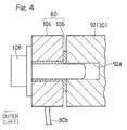
- the knock sensor 80 referred to previously is fitted to a left side end surface 30a on the opposite side of the cam chain 100.
- the knock sensor 80 is recommended to be disposed in the vicinity of the cylinder where the knocking is apt to occur.
- the knock sensor 80 is disposed in the vicinity of a first cylinder CY1 on the left side, which is ignited at the earliest timing in one cycle of the four cylinder combustion engine.
- the firing sequence is the first cylinder CY1, followed by the second cylinder CY2, followed by the fourth cylinder CY4 and finally followed by the third cylinder CY3.
- the cylinder where the knocking is apt to occur, is one of the cylinder that is ignited in advance of the neighboring cylinder.
- the first cylinder CY1 is ignited earlier than the neighboring second cylinder CY2
- the fourth cylinder CY4 is ignited earlier than the neighboring third cylinder CY3.
- the second cylinder CY2 is ignited after the ignition of the neighboring first cylinder CY1
- the third cylinder CY3 is ignited after the ignition of the neighboring fourth cylinder CY4.
- the cylinder that is ignited earlier than the next adjacent cylinder can guide a substantial amount of the high pressure intake air to the cylinder as compared with the cylinder that is ignited after the ignition of the neighboring cylinder, and therefore, a high output results in.
- the knock sensor 80 disposed in the vicinity of the cylinder that results in the high output as discussed above, the occurrence of the knocking can be effectively detected.
- each cylinder varies depending on, for example, the firing sequence, the ignition timing, the compression ratio, the shape of the intake air passage, the shape of the exhaust passage, the air-fuel mixing ratio, the intake air amount, the fuel supply amount and differences in characteristic of intake and exhaust valves
- the firing sequence may be changed so that, for example, the cylinder closer in position to the knock sensor 80 gives rise to a higher output than any other cylinders.
- Arrangement may be so made that by setting the ignition timing, the compression ratio, the shape of the passage, the air-fuel mixing ratio and others, besides the firing sequence, output of the cylinder closer in position to the knock sensor 80 can result in the higher output than that of any other neighboring cylinders.
- the knock sensor 80 is extended in the longitudinal direction and is then disposed in the vicinity of a main harness 98 that is used to electrically connect a fuel injection device, gauges and others with a control unit. Accordingly, a short lead 80b is sufficient to connect the knock sensor 80 with the main harness 98 and, therefore, the wiring can be easily accomplished.
- the knock sensor 80 shown in Fig. 3 is disposed in an end portion of the left side end surface 30a of the cylinder block 30 in the orthogonal direction X3, specifically in a rear end portion of the left side end surface 30a.
- the knock sensor 80 is disposed at a site proximate to an outer surface (rear surface) of the cylinder head 32 of the cylinder structural body, where the air intake port 54 is disposed, and at a portion (rear portion) proximate to the transmission casing 33.
- the knock sensor 80 is disposed on a rear side of the bolt hole 96 and the water jacket 90 formed inside the wall of the cylinder block 30.
- the knock sensor 80 includes a disc shaped sensor main body 104 and a one-side flanged collar 106 integrally inserted into a hollow of the disc shaped sensor main body 104, which collar 106 has a barrel portion 106a made of a metallic material and a collar portion 106b formed in the barrel portion 106a.
- peripheral components such as, for example, the coolant water intake opening 88, the balancer, the starter motor 82, the blow-by gas removal opening 86 and so on are disposed in the rear portion of the cylinder block 30.
- the knock sensor 80 is fitted to the left side end surface 30a of the cylinder block 30 , the space around the combustion engine can be efficiently utilized without permitting the knock sensor 80 to interfere with the peripheral components positioned rearwardly of the cylinder block 30. As a result, the assemblability and the maintenance capability of the knock sensor 80 are increased.
- the knock sensor 80 is disposed in the rear end portion of the left side end surface 30a of the cylinder block 30. Accordingly, vibrations of the cylinders CY2 to CY4 that are separated from the knock sensor 80 through walls of the cylinder block 30, which extend in the rotational axial direction X2 and the orthogonal direction (longitudinal direction) X3, can also be detected.
- the knock sensor 80 is disposed on a rear side of the water jacket 90 and the bolt hole 96. Accordingly, the vibrations from the cylinders CY1 to CY4 are transmitted directly to the knock sensor 80, bypassing the water jacket 90 and the bolt hole 96, and, therefore, the knocking can be precisely detected.
- the knock sensor 80 is disposed in the vicinity of a site proximate to an outer surface (rear surface) of the left side end surface 30a of the cylinder block 30, where the air intake port 54 (shown in Fig. 1 ) is disposed. Since the air intake side is lower in temperature than the exhaust side, temperature increase of the knock sensor 80 is suppressed.
- the knock sensor 80 is fitted to the left side end surface 30a of the cylinder block 30 which is on the side opposite to the cam chain 100. Accordingly, the space around the combustion engine E can be efficiently utilized without allowing the cam chain 100 and the knock sensor 80 to interfere with each other. Also, since the knock sensor 80 is disposed on the left side where a side stand 29 is disposed, even when no air intake duct 50 exist, the knock sensor 80 and the lead line 80b are hard to observe when the motorcycle is self-supported with the use of the side stand 29.
- the knock sensor 80 is disposed inwardly of the outer side end edge 27a of the generator covering 27 with respect to the vehicle widthwise direction. Accordingly, even when the motorcycle falls down laterally, the knock sensor 80 can be prevented by the generator covering 27 from being impaired.
- the knock sensor 80 is disposed in the vicinity of the first cylinder that is ignited at the earliest timing during the one cycle, the occurrence of the knocking can be effectively detected.
- vibrations are transmitted to the knock sensor 80 through a rear wall 30b of the cylinder block 30 and, therefore, the use of the only one knock sensor 80 is sufficient to detect the occurrence of knocking in any of the cylinders.
- the knock sensor 80 is disposed in the rear portion of the left side end surface 30a of the cylinder block 30, which is a site proximate to the transmission casing 33 (rear portion of the crankcase 28), and the supercharger 42 is disposed above the transmission casing 33. Accordingly, the space around the engine E can be further efficiently utilized.
- the knock sensor 80 is preferably disposed on the orthogonal direction outer side (rear side, according to the illustrated embodiment) of the bore of the cylinder. Also, the knock sensor 80 is preferably disposed in the orthogonal direction outside (rear side, according to the illustrated embodiment) of the water jacket 90. Further, the knock sensor 80 is preferably disposed on the rotational axial direction outer side (rear side, according to the illustrated embodiment) of the bolt hole 96 and/or in the orthogonal direction outer side (left side, according to the illustrated embodiment) of the bolt hole 96. Accordingly, detection of the vibration taking place in the cylinder at the position distant from the knock sensor 80 can be facilitated.
- the present invention is particularly applicable to the combustion engine having the supercharger mounted thereon, which is apt to be knocked.
- the supercharger may driven by, beside the rotational force of the crankshaft, the exhaust energies, the electric motor and others.
- the number of the knock sensors can be reduced and the manufacturing cost can be suppressed.
- the present invention can be suitably applied to the combustion engine of a type in which a plurality of the cylinders are juxtaposed in the rotational axial direction.
- the knock sensor 80 has been shown and described as fitted to the cylinder block 30 shown in Fig. 1 , but the knock sensor 80 may be fitted to the cylinder head 32. Where the knock sensor 80 is to be fitted to the cylinder block 30, positioning of the knock sensor 80 at an upper portion proximate to the combustion chamber 71 (shown in Fig. 3 ) is preferred. On the other hand, where the knock sensor 80 is to be fitted to the cylinder head 32, positioning of the knock sensor 80 at a lower portion proximate to the combustion chamber 71 (shown in Fig. 3 ) is preferred.
- auxiliary knock sensor may be additionally employed together with the knock sensor 80 so that by means of both of the knock sensors, the occurrence of knocking can be further accurately detected.
- the auxiliary knock sensor may be disposed at any arbitrarily chosen position, but positioning of it at a right side portion distant from the main knock sensor 80 is particularly preferred.
- the present invention is not necessarily limited thereto and can be equally applied to a two cylinder engine or a single cylinder engine with or without the supercharger mounted thereon.
- the present invention is also applicable to an engine for any vehicle other than the motorcycle, a marine engine or the like or any ground installed engine.
Landscapes
- Engineering & Computer Science (AREA)
- Chemical & Material Sciences (AREA)
- Combustion & Propulsion (AREA)
- Mechanical Engineering (AREA)
- General Engineering & Computer Science (AREA)
- Cylinder Crankcases Of Internal Combustion Engines (AREA)
- Combined Controls Of Internal Combustion Engines (AREA)
Applications Claiming Priority (1)
| Application Number | Priority Date | Filing Date | Title |
|---|---|---|---|
| PCT/JP2013/081038 WO2015072034A1 (fr) | 2013-11-18 | 2013-11-18 | Moteur |
Publications (3)
| Publication Number | Publication Date |
|---|---|
| EP3073100A1 true EP3073100A1 (fr) | 2016-09-28 |
| EP3073100A4 EP3073100A4 (fr) | 2017-04-19 |
| EP3073100B1 EP3073100B1 (fr) | 2018-06-27 |
Family
ID=53056994
Family Applications (1)
| Application Number | Title | Priority Date | Filing Date |
|---|---|---|---|
| EP13897336.7A Active EP3073100B1 (fr) | 2013-11-18 | 2013-11-18 | Moteur |
Country Status (5)
| Country | Link |
|---|---|
| US (1) | US20160215691A1 (fr) |
| EP (1) | EP3073100B1 (fr) |
| JP (1) | JP6302926B2 (fr) |
| CN (1) | CN105745422B (fr) |
| WO (1) | WO2015072034A1 (fr) |
Families Citing this family (2)
| Publication number | Priority date | Publication date | Assignee | Title |
|---|---|---|---|---|
| EP2878787B1 (fr) * | 2012-07-11 | 2019-08-21 | Kawasaki Jukogyo Kabushiki Kaisha | Système de lubrification pour moteur de véhicule |
| JP7046783B2 (ja) * | 2018-11-16 | 2022-04-04 | 本田技研工業株式会社 | 鞍乗り型車両 |
Family Cites Families (28)
| Publication number | Priority date | Publication date | Assignee | Title |
|---|---|---|---|---|
| JPS57143164A (en) * | 1981-02-26 | 1982-09-04 | Nippon Denso Co Ltd | Ignition timing controller |
| JPS5835232A (ja) * | 1981-08-26 | 1983-03-01 | Nissan Motor Co Ltd | 自動車用エンジンのノツクセンサ取付装置 |
| JPS5887429A (ja) * | 1981-11-20 | 1983-05-25 | Nissan Motor Co Ltd | ノツキング検出装置 |
| JPS58101224A (ja) * | 1981-12-10 | 1983-06-16 | Nissan Motor Co Ltd | 自動車用エンジンのシリンダブロツク |
| JPS58111364U (ja) * | 1982-01-26 | 1983-07-29 | 日産自動車株式会社 | ノツキング回避装置 |
| JPS59106029U (ja) * | 1983-01-05 | 1984-07-17 | 日産自動車株式会社 | V型エンジンのノック検出装置 |
| JPS59108228U (ja) * | 1983-01-11 | 1984-07-21 | マツダ株式会社 | ノツクセンサの取付構造 |
| JPH01140138U (fr) * | 1988-03-18 | 1989-09-26 | ||
| JPH03291545A (ja) * | 1990-04-09 | 1991-12-20 | Nissan Motor Co Ltd | ノック検出装置 |
| US5778857A (en) * | 1995-10-02 | 1998-07-14 | Yamaha Hatsudoki Kabushiki Kaisha | Engine control system and method |
| JP3959703B2 (ja) * | 2000-01-14 | 2007-08-15 | スズキ株式会社 | エンジンのノックセンサ取付構造 |
| JP2003322054A (ja) * | 2002-05-07 | 2003-11-14 | Mazda Motor Corp | エンジンのノックセンサ取付構造 |
| JP3827087B2 (ja) * | 2003-03-26 | 2006-09-27 | 三菱電機株式会社 | 内燃機関用ノックセンサの取付構造 |
| JP4236176B2 (ja) * | 2003-05-30 | 2009-03-11 | 本田技研工業株式会社 | 自動二輪車のエンジン支持構造 |
| FR2879665B1 (fr) * | 2004-12-17 | 2009-12-18 | Inst Francais Du Petrole | Methode de detection de combustion anormale pour moteurs a combustion interne |
| JP4888890B2 (ja) * | 2006-06-02 | 2012-02-29 | 本田技研工業株式会社 | 多気筒エンジンのノッキング制御装置 |
| JP2008063977A (ja) * | 2006-09-05 | 2008-03-21 | Yamaha Motor Co Ltd | 自動二輪車 |
| JP4734292B2 (ja) * | 2007-05-31 | 2011-07-27 | 本田技研工業株式会社 | ノックセンサの配置 |
| JP4844597B2 (ja) * | 2008-07-11 | 2011-12-28 | トヨタ自動車株式会社 | 内燃機関 |
| US8180519B2 (en) * | 2008-09-02 | 2012-05-15 | International Business Machines Corporation | Cooperative vehicle diagnostics |
| US8333072B2 (en) * | 2008-10-01 | 2012-12-18 | Honda Motor Co., Ltd. | Wastegate control system and method |
| JP5149878B2 (ja) * | 2009-08-27 | 2013-02-20 | 住友化学株式会社 | 透明樹脂積層板 |
| JP2011163252A (ja) * | 2010-02-12 | 2011-08-25 | Honda Motor Co Ltd | エンジン |
| US8245692B2 (en) * | 2010-12-03 | 2012-08-21 | Ford Global Technologies, Llc | Method and system for pre-ignition control |
| JP2013024101A (ja) * | 2011-07-20 | 2013-02-04 | Yamaha Motor Co Ltd | 内燃機関およびそれを備えた鞍乗型車両 |
| JP5901255B2 (ja) * | 2011-11-30 | 2016-04-06 | 株式会社ミクニ | 多連スロットル装置 |
| WO2014097737A1 (fr) * | 2012-12-19 | 2014-06-26 | 日本特殊陶業株式会社 | Capteur de cliquetis non résonant |
| JP6133820B2 (ja) * | 2014-06-27 | 2017-05-24 | トヨタ自動車株式会社 | 油圧制御弁の制御装置 |
-
2013
- 2013-11-18 JP JP2015547369A patent/JP6302926B2/ja active Active
- 2013-11-18 WO PCT/JP2013/081038 patent/WO2015072034A1/fr not_active Ceased
- 2013-11-18 EP EP13897336.7A patent/EP3073100B1/fr active Active
- 2013-11-18 CN CN201380080976.8A patent/CN105745422B/zh active Active
-
2016
- 2016-03-31 US US15/087,756 patent/US20160215691A1/en not_active Abandoned
Also Published As
| Publication number | Publication date |
|---|---|
| JPWO2015072034A1 (ja) | 2017-03-09 |
| CN105745422A (zh) | 2016-07-06 |
| JP6302926B2 (ja) | 2018-03-28 |
| US20160215691A1 (en) | 2016-07-28 |
| EP3073100B1 (fr) | 2018-06-27 |
| WO2015072034A1 (fr) | 2015-05-21 |
| EP3073100A4 (fr) | 2017-04-19 |
| CN105745422B (zh) | 2019-04-30 |
Similar Documents
| Publication | Publication Date | Title |
|---|---|---|
| US20130019657A1 (en) | Internal combustion engine and straddle-type vehicle equipped with the engine | |
| US8245683B2 (en) | Engine for vehicle | |
| US20080295577A1 (en) | Positional arrangement of knock sensor on a motorcycle engine, engine incorporating same, and motorcycle incorporating same | |
| JP4060226B2 (ja) | 内燃機関におけるノックセンサの取付構造 | |
| US7343906B2 (en) | Water jet propulsion boat | |
| JP2010014008A (ja) | オフロードビークル | |
| EP3073100B1 (fr) | Moteur | |
| JP3898935B2 (ja) | 船外機用4サイクルエンジン | |
| EP2549086B1 (fr) | Moteur à combustion interne et véhicule de type à enfourcher équipé du moteur | |
| EP1445468B1 (fr) | Moteur | |
| JPH1150855A (ja) | 船外機のエンジン装置 | |
| US7380533B2 (en) | Outboard motor provided with internal combustion engine having electrical equipment box | |
| US20050279092A1 (en) | Water jet propulsion boat | |
| JP6248534B2 (ja) | 過給機付自動二輪車 | |
| US6168484B1 (en) | Intake apparatus of outboard motor | |
| JP3900216B2 (ja) | 船外機のエンジン装置 | |
| EP4168663A1 (fr) | Bloc-cylindres d'un moteur à combustion interne | |
| EP2960479B1 (fr) | Structure de montage de capteur de cliquetis dans un moteur oscillant d'unité | |
| US7523735B2 (en) | Multiple-cylinder engine for outboard motor | |
| JP6771359B2 (ja) | 自動二輪車のノックセンサ配置構造 | |
| JP2019210893A (ja) | エンジン | |
| JP3900217B2 (ja) | 船外機のエンジン装置 | |
| JPH09207870A (ja) | スノーモービルのコントロールボックス | |
| JP2002235553A (ja) | 船外機 | |
| JP2007024006A (ja) | 空冷式内燃機関 |
Legal Events
| Date | Code | Title | Description |
|---|---|---|---|
| PUAI | Public reference made under article 153(3) epc to a published international application that has entered the european phase |
Free format text: ORIGINAL CODE: 0009012 |
|
| 17P | Request for examination filed |
Effective date: 20160330 |
|
| AK | Designated contracting states |
Kind code of ref document: A1 Designated state(s): AL AT BE BG CH CY CZ DE DK EE ES FI FR GB GR HR HU IE IS IT LI LT LU LV MC MK MT NL NO PL PT RO RS SE SI SK SM TR |
|
| AX | Request for extension of the european patent |
Extension state: BA ME |
|
| DAX | Request for extension of the european patent (deleted) | ||
| A4 | Supplementary search report drawn up and despatched |
Effective date: 20170317 |
|
| RIC1 | Information provided on ipc code assigned before grant |
Ipc: F02B 77/08 20060101ALI20170313BHEP Ipc: F02B 61/02 20060101ALI20170313BHEP Ipc: F02D 35/02 20060101ALI20170313BHEP Ipc: F02D 35/00 20060101AFI20170313BHEP |
|
| GRAP | Despatch of communication of intention to grant a patent |
Free format text: ORIGINAL CODE: EPIDOSNIGR1 |
|
| STAA | Information on the status of an ep patent application or granted ep patent |
Free format text: STATUS: GRANT OF PATENT IS INTENDED |
|
| RIC1 | Information provided on ipc code assigned before grant |
Ipc: F02B 77/08 20060101ALI20180111BHEP Ipc: F02B 61/02 20060101ALI20180111BHEP Ipc: F02D 35/00 20060101AFI20180111BHEP Ipc: F02D 35/02 20060101ALI20180111BHEP |
|
| INTG | Intention to grant announced |
Effective date: 20180209 |
|
| GRAS | Grant fee paid |
Free format text: ORIGINAL CODE: EPIDOSNIGR3 |
|
| GRAA | (expected) grant |
Free format text: ORIGINAL CODE: 0009210 |
|
| STAA | Information on the status of an ep patent application or granted ep patent |
Free format text: STATUS: THE PATENT HAS BEEN GRANTED |
|
| AK | Designated contracting states |
Kind code of ref document: B1 Designated state(s): AL AT BE BG CH CY CZ DE DK EE ES FI FR GB GR HR HU IE IS IT LI LT LU LV MC MK MT NL NO PL PT RO RS SE SI SK SM TR |
|
| REG | Reference to a national code |
Ref country code: GB Ref legal event code: FG4D |
|
| REG | Reference to a national code |
Ref country code: AT Ref legal event code: REF Ref document number: 1012563 Country of ref document: AT Kind code of ref document: T Effective date: 20180715 |
|
| REG | Reference to a national code |
Ref country code: IE Ref legal event code: FG4D |
|
| REG | Reference to a national code |
Ref country code: DE Ref legal event code: R096 Ref document number: 602013039579 Country of ref document: DE |
|
| PG25 | Lapsed in a contracting state [announced via postgrant information from national office to epo] |
Ref country code: FI Free format text: LAPSE BECAUSE OF FAILURE TO SUBMIT A TRANSLATION OF THE DESCRIPTION OR TO PAY THE FEE WITHIN THE PRESCRIBED TIME-LIMIT Effective date: 20180627 Ref country code: NO Free format text: LAPSE BECAUSE OF FAILURE TO SUBMIT A TRANSLATION OF THE DESCRIPTION OR TO PAY THE FEE WITHIN THE PRESCRIBED TIME-LIMIT Effective date: 20180927 Ref country code: SE Free format text: LAPSE BECAUSE OF FAILURE TO SUBMIT A TRANSLATION OF THE DESCRIPTION OR TO PAY THE FEE WITHIN THE PRESCRIBED TIME-LIMIT Effective date: 20180627 Ref country code: LT Free format text: LAPSE BECAUSE OF FAILURE TO SUBMIT A TRANSLATION OF THE DESCRIPTION OR TO PAY THE FEE WITHIN THE PRESCRIBED TIME-LIMIT Effective date: 20180627 Ref country code: BG Free format text: LAPSE BECAUSE OF FAILURE TO SUBMIT A TRANSLATION OF THE DESCRIPTION OR TO PAY THE FEE WITHIN THE PRESCRIBED TIME-LIMIT Effective date: 20180927 |
|
| REG | Reference to a national code |
Ref country code: NL Ref legal event code: MP Effective date: 20180627 |
|
| REG | Reference to a national code |
Ref country code: LT Ref legal event code: MG4D |
|
| PG25 | Lapsed in a contracting state [announced via postgrant information from national office to epo] |
Ref country code: RS Free format text: LAPSE BECAUSE OF FAILURE TO SUBMIT A TRANSLATION OF THE DESCRIPTION OR TO PAY THE FEE WITHIN THE PRESCRIBED TIME-LIMIT Effective date: 20180627 Ref country code: GR Free format text: LAPSE BECAUSE OF FAILURE TO SUBMIT A TRANSLATION OF THE DESCRIPTION OR TO PAY THE FEE WITHIN THE PRESCRIBED TIME-LIMIT Effective date: 20180928 Ref country code: LV Free format text: LAPSE BECAUSE OF FAILURE TO SUBMIT A TRANSLATION OF THE DESCRIPTION OR TO PAY THE FEE WITHIN THE PRESCRIBED TIME-LIMIT Effective date: 20180627 Ref country code: HR Free format text: LAPSE BECAUSE OF FAILURE TO SUBMIT A TRANSLATION OF THE DESCRIPTION OR TO PAY THE FEE WITHIN THE PRESCRIBED TIME-LIMIT Effective date: 20180627 |
|
| REG | Reference to a national code |
Ref country code: AT Ref legal event code: MK05 Ref document number: 1012563 Country of ref document: AT Kind code of ref document: T Effective date: 20180627 |
|
| PG25 | Lapsed in a contracting state [announced via postgrant information from national office to epo] |
Ref country code: NL Free format text: LAPSE BECAUSE OF FAILURE TO SUBMIT A TRANSLATION OF THE DESCRIPTION OR TO PAY THE FEE WITHIN THE PRESCRIBED TIME-LIMIT Effective date: 20180627 |
|
| PG25 | Lapsed in a contracting state [announced via postgrant information from national office to epo] |
Ref country code: PL Free format text: LAPSE BECAUSE OF FAILURE TO SUBMIT A TRANSLATION OF THE DESCRIPTION OR TO PAY THE FEE WITHIN THE PRESCRIBED TIME-LIMIT Effective date: 20180627 Ref country code: SK Free format text: LAPSE BECAUSE OF FAILURE TO SUBMIT A TRANSLATION OF THE DESCRIPTION OR TO PAY THE FEE WITHIN THE PRESCRIBED TIME-LIMIT Effective date: 20180627 Ref country code: EE Free format text: LAPSE BECAUSE OF FAILURE TO SUBMIT A TRANSLATION OF THE DESCRIPTION OR TO PAY THE FEE WITHIN THE PRESCRIBED TIME-LIMIT Effective date: 20180627 Ref country code: AT Free format text: LAPSE BECAUSE OF FAILURE TO SUBMIT A TRANSLATION OF THE DESCRIPTION OR TO PAY THE FEE WITHIN THE PRESCRIBED TIME-LIMIT Effective date: 20180627 Ref country code: IS Free format text: LAPSE BECAUSE OF FAILURE TO SUBMIT A TRANSLATION OF THE DESCRIPTION OR TO PAY THE FEE WITHIN THE PRESCRIBED TIME-LIMIT Effective date: 20181027 Ref country code: CZ Free format text: LAPSE BECAUSE OF FAILURE TO SUBMIT A TRANSLATION OF THE DESCRIPTION OR TO PAY THE FEE WITHIN THE PRESCRIBED TIME-LIMIT Effective date: 20180627 Ref country code: RO Free format text: LAPSE BECAUSE OF FAILURE TO SUBMIT A TRANSLATION OF THE DESCRIPTION OR TO PAY THE FEE WITHIN THE PRESCRIBED TIME-LIMIT Effective date: 20180627 |
|
| PG25 | Lapsed in a contracting state [announced via postgrant information from national office to epo] |
Ref country code: SM Free format text: LAPSE BECAUSE OF FAILURE TO SUBMIT A TRANSLATION OF THE DESCRIPTION OR TO PAY THE FEE WITHIN THE PRESCRIBED TIME-LIMIT Effective date: 20180627 Ref country code: ES Free format text: LAPSE BECAUSE OF FAILURE TO SUBMIT A TRANSLATION OF THE DESCRIPTION OR TO PAY THE FEE WITHIN THE PRESCRIBED TIME-LIMIT Effective date: 20180627 Ref country code: IT Free format text: LAPSE BECAUSE OF FAILURE TO SUBMIT A TRANSLATION OF THE DESCRIPTION OR TO PAY THE FEE WITHIN THE PRESCRIBED TIME-LIMIT Effective date: 20180627 |
|
| REG | Reference to a national code |
Ref country code: DE Ref legal event code: R097 Ref document number: 602013039579 Country of ref document: DE |
|
| PLBE | No opposition filed within time limit |
Free format text: ORIGINAL CODE: 0009261 |
|
| STAA | Information on the status of an ep patent application or granted ep patent |
Free format text: STATUS: NO OPPOSITION FILED WITHIN TIME LIMIT |
|
| PG25 | Lapsed in a contracting state [announced via postgrant information from national office to epo] |
Ref country code: DK Free format text: LAPSE BECAUSE OF FAILURE TO SUBMIT A TRANSLATION OF THE DESCRIPTION OR TO PAY THE FEE WITHIN THE PRESCRIBED TIME-LIMIT Effective date: 20180627 |
|
| 26N | No opposition filed |
Effective date: 20190328 |
|
| REG | Reference to a national code |
Ref country code: CH Ref legal event code: PL |
|
| GBPC | Gb: european patent ceased through non-payment of renewal fee |
Effective date: 20181118 |
|
| PG25 | Lapsed in a contracting state [announced via postgrant information from national office to epo] |
Ref country code: MC Free format text: LAPSE BECAUSE OF FAILURE TO SUBMIT A TRANSLATION OF THE DESCRIPTION OR TO PAY THE FEE WITHIN THE PRESCRIBED TIME-LIMIT Effective date: 20180627 Ref country code: LU Free format text: LAPSE BECAUSE OF NON-PAYMENT OF DUE FEES Effective date: 20181118 |
|
| REG | Reference to a national code |
Ref country code: BE Ref legal event code: MM Effective date: 20181130 |
|
| REG | Reference to a national code |
Ref country code: IE Ref legal event code: MM4A |
|
| PG25 | Lapsed in a contracting state [announced via postgrant information from national office to epo] |
Ref country code: CH Free format text: LAPSE BECAUSE OF NON-PAYMENT OF DUE FEES Effective date: 20181130 Ref country code: SI Free format text: LAPSE BECAUSE OF FAILURE TO SUBMIT A TRANSLATION OF THE DESCRIPTION OR TO PAY THE FEE WITHIN THE PRESCRIBED TIME-LIMIT Effective date: 20180627 Ref country code: LI Free format text: LAPSE BECAUSE OF NON-PAYMENT OF DUE FEES Effective date: 20181130 |
|
| PG25 | Lapsed in a contracting state [announced via postgrant information from national office to epo] |
Ref country code: IE Free format text: LAPSE BECAUSE OF NON-PAYMENT OF DUE FEES Effective date: 20181118 |
|
| PG25 | Lapsed in a contracting state [announced via postgrant information from national office to epo] |
Ref country code: AL Free format text: LAPSE BECAUSE OF FAILURE TO SUBMIT A TRANSLATION OF THE DESCRIPTION OR TO PAY THE FEE WITHIN THE PRESCRIBED TIME-LIMIT Effective date: 20180627 Ref country code: BE Free format text: LAPSE BECAUSE OF NON-PAYMENT OF DUE FEES Effective date: 20181130 |
|
| PG25 | Lapsed in a contracting state [announced via postgrant information from national office to epo] |
Ref country code: GB Free format text: LAPSE BECAUSE OF NON-PAYMENT OF DUE FEES Effective date: 20181118 |
|
| PG25 | Lapsed in a contracting state [announced via postgrant information from national office to epo] |
Ref country code: MT Free format text: LAPSE BECAUSE OF NON-PAYMENT OF DUE FEES Effective date: 20181118 |
|
| PG25 | Lapsed in a contracting state [announced via postgrant information from national office to epo] |
Ref country code: TR Free format text: LAPSE BECAUSE OF FAILURE TO SUBMIT A TRANSLATION OF THE DESCRIPTION OR TO PAY THE FEE WITHIN THE PRESCRIBED TIME-LIMIT Effective date: 20180627 |
|
| PG25 | Lapsed in a contracting state [announced via postgrant information from national office to epo] |
Ref country code: PT Free format text: LAPSE BECAUSE OF FAILURE TO SUBMIT A TRANSLATION OF THE DESCRIPTION OR TO PAY THE FEE WITHIN THE PRESCRIBED TIME-LIMIT Effective date: 20180627 |
|
| PG25 | Lapsed in a contracting state [announced via postgrant information from national office to epo] |
Ref country code: CY Free format text: LAPSE BECAUSE OF FAILURE TO SUBMIT A TRANSLATION OF THE DESCRIPTION OR TO PAY THE FEE WITHIN THE PRESCRIBED TIME-LIMIT Effective date: 20180627 Ref country code: MK Free format text: LAPSE BECAUSE OF NON-PAYMENT OF DUE FEES Effective date: 20180627 Ref country code: HU Free format text: LAPSE BECAUSE OF FAILURE TO SUBMIT A TRANSLATION OF THE DESCRIPTION OR TO PAY THE FEE WITHIN THE PRESCRIBED TIME-LIMIT; INVALID AB INITIO Effective date: 20131118 |
|
| PGFP | Annual fee paid to national office [announced via postgrant information from national office to epo] |
Ref country code: FR Payment date: 20201013 Year of fee payment: 8 |
|
| REG | Reference to a national code |
Ref country code: DE Ref legal event code: R081 Ref document number: 602013039579 Country of ref document: DE Owner name: KAWASAKI MOTORS, LTD., AKASHI-SHI, JP Free format text: FORMER OWNER: KAWASAKI JUKOGYO KABUSHIKI KAISHA, KOBE-SHI, HYOGO, JP |
|
| PG25 | Lapsed in a contracting state [announced via postgrant information from national office to epo] |
Ref country code: FR Free format text: LAPSE BECAUSE OF NON-PAYMENT OF DUE FEES Effective date: 20211130 |
|
| PGFP | Annual fee paid to national office [announced via postgrant information from national office to epo] |
Ref country code: DE Payment date: 20250930 Year of fee payment: 13 |