EP3141506A1 - Drahtbehälterdeckel, drahtbehälter und drahtzuführungssystem - Google Patents
Drahtbehälterdeckel, drahtbehälter und drahtzuführungssystem Download PDFInfo
- Publication number
- EP3141506A1 EP3141506A1 EP16180212.9A EP16180212A EP3141506A1 EP 3141506 A1 EP3141506 A1 EP 3141506A1 EP 16180212 A EP16180212 A EP 16180212A EP 3141506 A1 EP3141506 A1 EP 3141506A1
- Authority
- EP
- European Patent Office
- Prior art keywords
- wire
- wall
- container
- ring
- lid
- Prior art date
- Legal status (The legal status is an assumption and is not a legal conclusion. Google has not performed a legal analysis and makes no representation as to the accuracy of the status listed.)
- Granted
Links
Images



Classifications
-
- B—PERFORMING OPERATIONS; TRANSPORTING
- B65—CONVEYING; PACKING; STORING; HANDLING THIN OR FILAMENTARY MATERIAL
- B65H—HANDLING THIN OR FILAMENTARY MATERIAL, e.g. SHEETS, WEBS, CABLES
- B65H57/00—Guides for filamentary materials; Supports therefor
- B65H57/18—Guides for filamentary materials; Supports therefor mounted to facilitate unwinding of material from packages
-
- B—PERFORMING OPERATIONS; TRANSPORTING
- B23—MACHINE TOOLS; METAL-WORKING NOT OTHERWISE PROVIDED FOR
- B23K—SOLDERING OR UNSOLDERING; WELDING; CLADDING OR PLATING BY SOLDERING OR WELDING; CUTTING BY APPLYING HEAT LOCALLY, e.g. FLAME CUTTING; WORKING BY LASER BEAM
- B23K9/00—Arc welding or cutting
- B23K9/12—Automatic feeding or moving of electrodes or work for spot or seam welding or cutting
- B23K9/133—Means for feeding electrodes, e.g. drums, rolls, motors
- B23K9/1333—Dereeling means
-
- B—PERFORMING OPERATIONS; TRANSPORTING
- B65—CONVEYING; PACKING; STORING; HANDLING THIN OR FILAMENTARY MATERIAL
- B65D—CONTAINERS FOR STORAGE OR TRANSPORT OF ARTICLES OR MATERIALS, e.g. BAGS, BARRELS, BOTTLES, BOXES, CANS, CARTONS, CRATES, DRUMS, JARS, TANKS, HOPPERS, FORWARDING CONTAINERS; ACCESSORIES, CLOSURES, OR FITTINGS THEREFOR; PACKAGING ELEMENTS; PACKAGES
- B65D43/00—Lids or covers for rigid or semi-rigid containers
- B65D43/02—Removable lids or covers
-
- B—PERFORMING OPERATIONS; TRANSPORTING
- B65—CONVEYING; PACKING; STORING; HANDLING THIN OR FILAMENTARY MATERIAL
- B65D—CONTAINERS FOR STORAGE OR TRANSPORT OF ARTICLES OR MATERIALS, e.g. BAGS, BARRELS, BOTTLES, BOXES, CANS, CARTONS, CRATES, DRUMS, JARS, TANKS, HOPPERS, FORWARDING CONTAINERS; ACCESSORIES, CLOSURES, OR FITTINGS THEREFOR; PACKAGING ELEMENTS; PACKAGES
- B65D85/00—Containers, packaging elements or packages, specially adapted for particular articles or materials
- B65D85/02—Containers, packaging elements or packages, specially adapted for particular articles or materials for annular articles
- B65D85/04—Containers, packaging elements or packages, specially adapted for particular articles or materials for annular articles for coils of wire, rope or hose
-
- B—PERFORMING OPERATIONS; TRANSPORTING
- B65—CONVEYING; PACKING; STORING; HANDLING THIN OR FILAMENTARY MATERIAL
- B65H—HANDLING THIN OR FILAMENTARY MATERIAL, e.g. SHEETS, WEBS, CABLES
- B65H49/00—Unwinding or paying-out filamentary material; Supporting, storing or transporting packages from which filamentary material is to be withdrawn or paid-out
- B65H49/02—Methods or apparatus in which packages do not rotate
- B65H49/04—Package-supporting devices
- B65H49/06—Package-supporting devices for a single operative package
- B65H49/08—Package-supporting devices for a single operative package enclosing the package
-
- B—PERFORMING OPERATIONS; TRANSPORTING
- B65—CONVEYING; PACKING; STORING; HANDLING THIN OR FILAMENTARY MATERIAL
- B65H—HANDLING THIN OR FILAMENTARY MATERIAL, e.g. SHEETS, WEBS, CABLES
- B65H57/00—Guides for filamentary materials; Supports therefor
- B65H57/12—Tubes
-
- B—PERFORMING OPERATIONS; TRANSPORTING
- B65—CONVEYING; PACKING; STORING; HANDLING THIN OR FILAMENTARY MATERIAL
- B65H—HANDLING THIN OR FILAMENTARY MATERIAL, e.g. SHEETS, WEBS, CABLES
- B65H75/00—Storing webs, tapes, or filamentary material, e.g. on reels
- B65H75/02—Cores, formers, supports, or holders for coiled, wound, or folded material, e.g. reels, spindles, bobbins, cop tubes, cans, mandrels or chucks
- B65H75/04—Kinds or types
- B65H75/16—Cans or receptacles, e.g. sliver cans
-
- B—PERFORMING OPERATIONS; TRANSPORTING
- B65—CONVEYING; PACKING; STORING; HANDLING THIN OR FILAMENTARY MATERIAL
- B65H—HANDLING THIN OR FILAMENTARY MATERIAL, e.g. SHEETS, WEBS, CABLES
- B65H2701/00—Handled material; Storage means
- B65H2701/30—Handled filamentary material
- B65H2701/36—Wires
Definitions
- the invention relates to a wire container lid for closing an upper side of a wire box filled with coiled wire, in particular for a welding wire container lid. Furthermore, the invention relates to a wire container, in particular a welding wire container, and to a wire feeding system comprising a wire container.
- Such wire containers usually comprise coiled steel and aluminum welding wires or metal spray wires or any other wire in applications where the wire is paid out from a large bulk container, pack or drum.
- Wire feeding systems are commonly used for feeding welding wires from a supply source, for example a container in which a significant amount (up to more than one ton) of welding wire is being stored, to a point called welding arc where the welding wire is being deposited through a welding torch, with the purpose of joining metal parts.
- a supply source for example a container in which a significant amount (up to more than one ton) of welding wire is being stored, to a point called welding arc where the welding wire is being deposited through a welding torch, with the purpose of joining metal parts.
- the welding wire is drawn from a manufacturing process and runs over rollers, is pulled along by a capstan and is fed into a rotatable cylindrical tube comprising an opening at the bottom or along the cylinder adjacent to the bottom. The wire extends through the tube and out the opening, whereupon it is placed into the storage container.
- the tube protrudes into the storage container and rotates about an axis parallel to the storage container axis.
- the wire is fed into the tube by the capstan and at a rotational velocity different than the rotational velocity of the tube.
- a ratio between the rotational velocities of the tube and the capstan defines a loop size diameter of the wire within the storage container.
- twist-free winding however is not a simple process and it can be negatively affected by a number of variables, like the columnar strength of the wire, its diameter or its surface condition.
- aluminum welding wires are difficult to become plastically deformed and pre-twisted, because of their elasticity; moreover their rougher surface condition increases the friction and complicates the feeding through the conduit guiding the wire into the pack.
- the twist-free winding machines of most recent construction are provided with a variety of controls and adjusting options, it is virtually impossible to continuously and dynamically compensate the inevitable wire deformations and defects.
- twist-free torsion-free winding machine is unable to completely eliminate the residual wire tension while laying it down into the container, this residual tension increasingly accumulates on the wire during the payout process until the wire is so loaded that it will eventually tangle and jam inside the pack and cause an unwanted interruption of the welding process.
- unwanted weld interruptions caused by wire tangles can be extremely expensive and can impact the complete production line with costly production downtime, bad welds and weld repairs.
- the present invention provides a wire container lid for closing an upper side of a wire box filled with coiled wire, the lid comprising a front wall having an opening through which wire is to be paid off, a wire outlet guide attached to the front wall, the wire outlet guide comprising an upper and a lower hole for receiving the wire, the upper and lower holes being defined by a lower ring wall and an upper ring wall, respectively, and being distanced from each other in a wire feeding direction, at least the lower ring wall limiting sideward movement of the wire and allowing contact with the wire, ring the holes having a fixed position relative to the front wall, and a deflection space bridging the distance between the holes for allowing sideward deflection and swing of the wire between the ring walls.
- the present invention provides a wire container lid which can be used with wire boxes of conventional design.
- the wire container lid provides a wire outlet guide of a specific length which comprises two separate ring walls which limits two holes defining strictures with respect to the deflection space. At least the lower limits the sideward movement of the wire and guides the wire.
- the strictures are distanced by a deflection space in which the wire is allowed to sidewardly deflect and sidewardly swing contrary to the holes.
- the wire outlet guide of the lid according to the present invention has no rotating holes of the wire outlet guide rather than holes having a fixed, permanent position with respect to the container.
- the wire is allowed to deflect between a first, inlet hole (lower hole) and a second, outlet hole (upper hole).
- the wire outlet guide can be fixedly or shiftably attached to the front wall, and both can be separately produced and attached to each other. If a gap between the wire outlet guide and the front wall is provided, this gap can be closed and sealed by a brush, flexible rubber or foam.
- the wire outlet guide may have a connection wall connecting the ring walls to each other.
- the connection wall is radially distanced by at least 10 mm from a virtual cylinder of maximum cross-section extending through both holes and contacting at least one ring wall. The connection wall, therefore, allows the deflection of the wire between the ring walls.
- connection wall can be defined by one or more rods.
- connection wall has one of a box-like and tube-like shape limiting an interior which defines the deflection space.
- the connection wall can be circumferentially closed and cylindrical so that the wire is protected by the connection wall and cannot get caught by the wall.
- connection wall can be transparent, e.g. of plexiglass, allowing a visual access of the wire during its payoff.
- connection wall may further carry an upper and a lower front wall closing the deflection space in axial direction.
- the upper wall comprises or carries the upper ring wall
- the lower front wall carries or comprises the lower ring wall. Therefore, the deflection space is able to protect the wire from possible contamination.
- At least one of the ring walls can be defined by a ring-shaped insert part allowing to replace the insert part or to provide a quite low-quality end wall as friction occurs between the wire and the insert part. It would even be possible to produce the end walls by cardboard or plastic.
- the ring-shaped insert can be a nozzle made of a material having a higher hardness than the material of the wire, e.g. a nozzle made of a ceramic.
- the ring walls are distanced from each other by 350 to 600 mm.
- the inner diameter of the deflection space can be between 50 and 120 mm.
- the front wall has a lower side facing the interior of the box and an opposite upper side.
- the wire outlet guide protrudes from at least one of the upper and lower sides, i.e. the outlet guide may be attached to the front wall so as to protrude only to the inside of the box or protrude only to the outside of the box or, protrudes both to the inside and to the outside of the box.
- the wire outlet guide can be shifted or displaced in the feeding direction relative to the front wall.
- the tube-like or box-like wire outlet guide is pushed to extend completely or mainly into the interior of the box.
- the wire outlet guide may be pulled to mainly or completely extend out of the box and to protrude from the upper side of the front wall so that there is a larger distance between the lower, insert hole of the wire outlet guide and the upper end of the wire coil package within the box.
- the ring walls are defining an upper ring wall and a lower ring wall.
- the lower ring wall is closer to the interior of the box than the upper ring wall.
- the upper ring wall may define the wire guide of the lid which is most distanced from the front wall on its upper side, i.e., there is no further guide means provided on the lid.
- the wire After the container, the wire enters a wire guiding conduit which extends over several meters or dozens of meters to a wire consumer, e.g. a welding tool.
- the wire guiding conduit can be distanced from the upper ring wall or can be coupled to the upper ring wall by a quick coupling at the upper ring wall allowing an immediate decoupling from and coupling to an empty and a full container, respectively.
- the quick coupling part attached to the upper end wall can define the upper hole of the wire outlet guide.
- wire feeding systems are provided with wire rear feeders which include driven rollers arranged between the container and the wire guiding conduit. These wire rear feeders support wire front feeders arranged close to the welding tool.
- a quick coupling means at the upper ring wall even allows to simply and quickly attach the wire rear feeder to the container. The quick coupling further ensures a correct, firm position of the wire guiding conduit or the wire rear feeder relative to the wire outlet guide and its holes.
- the present invention further comprises a wire container with a box having an open upper side and a wire which is coiled in the box and extends through the holes of the wire container lid according to the present invention.
- the wire is able to sidewardly deflect in the deflection space, whereas it is guided at least within the lower hole.
- the front wall of the lid can be flat or provided with a central dome protruding outwardly.
- the dome comprises the wire outlet guide, i.e. the wire outlet guide is attached to the dome.
- the central dome could be of plastic and could be integrally formed with the transparent connection wall.
- a retainer ring lying on the top of a package of coiled wire within the container improves controlled wire payoff.
- the wire freely extends from below the retainer ring to the lower hole of the wire outlet guide without any wire guiding means arranged therebetween. Therefore, the wire is guided between the retainer ring and the outside, i.e. the environment of the container, by the wire outlet guide, only.
- the lid may have a circumferentially extending cylindrical wall protruding from an circumferential edge of the front wall and encompassing an upper end area of the box sidewall.
- the lid is fixed in sideward direction to and on the box.
- the lid is shiftable between a low position in which the front wall is close to or rests on an upper edge of the sidewall and a raised position in which the front wall is distanced from the upper edge and in which the container has a larger inner volume than in the low position.
- the box sidewall has at least one sidewardly protruding stop portion for the lid on which the lid rests in the raised position.
- the lifting of the lid allows to increase the distance between the upper end of the package of coiled wire and the lower hole of the wire outlet guide. By increasing this distance, the wire is allowed to freely move or swing within the container so that the risk of the wire tangling or jamming inside the pack is further reduced.
- the stop portion can be a portion of the box sidewall which is defined by a cut in the box sidewall and which is bent outwardly along a hinge portion in which the stop integrally extends into the remainder of the box sidewall.
- the cut could be a V- or U-shaped cut so that a tongue-like portion of the sidewall is circumscribed by the cut. The tongue, however, remains attached to the remainder of the box sidewall.
- the present invention further provides a wire feeding system comprising a wire container according to the present invention as described above.
- the wire is coiled in the box to form a package and extends through the holes of the wire outlet guide.
- a wire conduit e.g. a tube, for transporting the wire to a tool or consumer has an inlet end for the inlet of the wire from the container.
- the inlet end can be distanced from the container or can be immediately attached to the container at the upper ring wall.
- a quick coupling at the upper ring wall can be provided.
- the wire conduit is spaced from the container and from the upper ring wall of the wire outlet guide, a free space between the conduit and the container may allow deflection and swinging of the wire sidewardly.
- the inlet end of the wire conduit could also be arranged immediately adjacent to the upper ring wall or attached to the upper ring wall.
- a wire rear feeder device can be arranged between the upper ring wall and the inlet end of the wire conduit.
- the wire rear feeder may adjoin the upper ring wall or be slightly or significantly distanced therefrom. A quick coupling allows connecting the wire rear feeder to the wire outlet guide.
- the tube or the box defining the connecting wall can be of any material, plastic or cardboard but a transparent material like plexiglas is recommended to allow a visual inspection of the passing wire.
- the connecting wall has a wider rim at its upper end which will prevent it from inadvertently falling inside the container and this feature will facilitate the operator who can temporarily push the tube completely inside the pack during the initial wire insertion and then easily pull it up and connect it to the feeder device or the conduit to start the welding process.
- a gap between the connecting wall and the front wall can be sealed with a brush or a soft rubber gasket, to prevent dirt, dust or misture from penetrating inside the pack, thus affecting the wire.
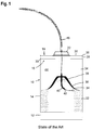
- Figure 1 shows a first prior art wire container of a wire feeding system.
- the wire container comprises a box 10 having a closed bottom 12 from which a box sidewall 14 protrudes upwardly.
- the box sidewall 14 is circumferentially closed and defines a cylinder.
- Box 10 has an upper open end 16 which is closed by a lid 18.
- Lid 18 is pot-shaped and comprises a front wall 20 having a central dome 22 which protrudes upwardly, i.e. away from the interior 24 of the container.
- Front wall 20 has an outer, circumferential edge 26 from which a cylindrical, circumferentially closed wall 28 protrudes downwardly.
- Cylindrical wall 28 encompasses an upper end area 30 of the box sidewall 14 to be sidewardly fixed and attached to box 10.
- a package 32 of coiled welding wire 34 of steel or aluminum (or a metal spray wire or any other wire) is housed.
- a retainer 36 rests on the upper end of package 32 and has a conical, dome-shaped design.
- Retainer 36 carries a guiding tube 38 which has a bow-shaped lower end portion 40 with an inlet hole 42 facing the upper, inner end of package 32.
- Tube 38 is attached to retainer 36 in a rotational manner so that inlet hole 42 has no fixed position relative to box 10.
- Welding wire 34 is protruding from the upper end of package 32 through inlet hole 42 into a space 44 within the container which is empty and which extends from the upper side of retainer 36 to lid 18.
- Conduit 46 is attached to dome 22 and extends to a wire consumer, e.g. a welding tool. Conduit 46 can be easily decoupled from lid 18.
- Welding wire 34 is pulled and paid off from the container by a driving means, e.g. a front feeding system arranged close to the consumer, i.e. to the welding tool.
- a driving means e.g. a front feeding system arranged close to the consumer, i.e. to the welding tool.
- welding wire 34 is tensioned between dome 22 and the upper end of tube 38.
- tube 38 rotates within retainer 36.
- FIG 2 shows a further embodiment according to the prior art, wherein corresponding parts or portions which have already been introduced by Figure 1 carry the same reference numerals. In the following, the differences to the embodiment according to Figure 1 are discussed, only.
- Retainer 36 is replaced by a retainer ring 36' which rests on wire package 32 but is not closed rather than fully open within the ring-shaped wire package (seen from above).
- Tube 38 is rotatably attached to dome 22 so that welding wire 34 extends bow-shaped portion 40 and is tensioned between retainer ring 36' and inlet hole 42.
- the third embodiment according to prior art solutions shown in Figure 3 differs from the Figure 2 embodiment by not having a rotatable tube 38. Instead, welding wire 34 is not guided between retainer ring 36' and conduit 46.
- Figure 4 shows a wire feeding system with a wire container having a specific lid.
- the container shown in Figure 4 does not comprise a rotatable tube-like tube 38 as shown in Figures 1 and 2 having a bent lower end facing to the upper end of the package 32.
- a wire outlet guide 50 which is separately shown in Figures 9 and 10 is provided and attached to lid 18. It is to be emphasized that lid 18 can have a central dome 22 which, however, is not obligatory. Generally speaking, wire outlet guide 50 is arranged at the central point of lid 18 and its front wall 20.
- Wire outlet guide 50 is box- or tube-like and has a lower end wall 52 with a central ring wall 54 circumscribing a lower hole 56 through which welding wire extends when being paid off from package 32.
- Ring wall 54 is defined by a ring-shaped insert part in the form of a nozzle made of a material having a higher hardness than the material of the wire. More specifically, the ring-shaped insert part is made of ceramics.
- An upper end wall 58 which is also nozzle-shaped and has a conically inner surface 60 is distanced from lower end wall 52 by a connection wall 62.
- Connection wall 62 is box-like or tube-like and preferably circular cylindrical.
- Connection wall 62 can be of transparent material, e.g. of plexiglass, in order to allow inspection of wire 34 protruding through wire outlet guide 50. If front wall 20 or its dome 22 are partly or fully of transparent material, movement and extension of wire 34 within the container can be monitored from the outside during the welding operation.
- Wire 34 extends through an upper hole 64 in upper end wall 58 to the outside of the container.
- Upper end wall 58 can be provided with a quick coupling 70 which can be permanently or removably attached from the remainder of upper end wall 58.
- Upper end wall 58 or its ring-shaped quick coupling 70 defines the portion of the upper hole 64 having the smallest diameter or cross sectional area through which wire 34 is guided and at which wire may contact the corresponding upper ring wall, i. e. the area of the hole having the smallest diameter or cross-sectional area.
- the upper ring wall 72 is provided in end wall 58.
- Quick coupling 70 may, however, facilitate attachment of conduit 46 or a wire rear feeder 74 which drives wire 34 and supports a wire front feeder arranged close to or at a welding tool.
- connection wall 62 is significantly larger than the diameter or the cross-section of upper and lower holes 64 and 56.
- Connection wall 62 is significantly larger than the diameters and the cross-sections of lower hole 56 and upper hole 64.
- Lower hole 56, upper hole 64 and the radial inner side of connection wall 62 are coaxially arranged to each other.
- the inner diameter or cross-section of hole 56 can be slightly smaller than the diameter or cross-sectional area of upper hole 64.
- a virtual cylinder 76 of maximum diameter or cross sectional area contacting the smaller of one of holes 56 and 64 and coaxially extending through both holes 56 and 64 is shown in broken lines in Figure 9 .
- the inner surface of connecting wall 62 is distanced from virtual cylinder 76 by at least 10 mm (see radius I).
- a deflection space 78 is defined by the hollow interior of connection wall 62 and by end or ring walls 52 and 58.
- the axial length (which is the wire feeding direction) of the deflection space i.e. the axial distance of the ring walls 52 and 58 is 350 to 600 mm.
- This axial length and the radial dimension of the deflection space in connection with the diameters of holes 56 and 64 allow wire 34 to freely swing, float and deflect sidewards within deflection space 78 as can be seen from Figure 9 . It has been proven that slightly tensioned wire when passing through hole 56 is able to freely move and swing within deflection space 78 in order not to build up sufficient tension to cause knots.
- the tension of wire 34 is not built up or discharged in the wire portion between package 32 and lower hole 56. Instead, the tension is kept and discharged within wire outlet guide 50.
- hole 64 and its ring wall 72 are the wire guide of lid 18 which is most distanced from front wall 20 on its upper side.
- At least one of the ring walls 54 and 64 define the only wire guide of the container between retainer ring 36' and the outside of the container.
- wire 34 can freely extend from below retainer ring 36' to the lower hole 56 without a wire guiding means arranged therebetween.
- Wire outlet guide 50 can be fixedly attached to front wall 20 or can be axially displaceable, i.e. vertically displaceable attached to front wall 20.
- Connection wall 62 extends or may extend through a corresponding opening in front wall 20 or dome 22.
- wire outlet guide 50 may completely or almost completely protrude into the interior of container as shown in Figure 4 or mainly or completely protrude out of the container as shown in Figure 5 .
- a sealing means 80 (see Figure 8 ) seals and bridges a potential gap between front wall 20 and the outer surface of connection wall 62.
- Sealing means 80 can be a brush, a flexible rubber or foam. Sealing means 80 further could be the only means to attach and align wire outlet guide to front wall 20.
- wire rear feeder 74 is arranged distanced from hole 64 to define a free space 84 in which wire 34 can deflect sidewardly, depending on the tension by which wire 34 is pulled out of the container.
- the tube-shaped wire outlet guide 50 is shifted almost completely out from the container or is permanently and fixedly attached to front wall 20 to protrude from the upper side of front wall 20.
- wire outlet guide 50 bridges the distance between front wall 20 and its dome 22 and wire rear feeder 74.
- Quick coupling 70 may allow attachment of the other end of wire outlet guide to wire rear feeder 74.
- wire outlet guide 50 is attached to front wall 20 and wire rear feeder 74.
- the distance between retainer ring 36' and first and lower hole 56 is increased compared with the embodiment according to Figure 4 .
- the embodiment according to Figure 6 corresponds to the embodiment according to Figure 4
- the embodiment according to Figure 7 corresponds to the embodiment according to Figure 5 , wherein in both figures no wire rear feeder 74 is used. Therefore, wire 34 when leaving wire outlet guide 50 is guided outside of the container by conduit 46.
- the free space 84 is arranged between the inlet of conduit 46 and the wire outlet guide 50.
- wire outlet guide 50 is coupled to conduit 46 by quick coupling 70.
- a radially outwardly extending rim 86 at the upper end of the connection wall ensures that the wire outlet guide cannot fall into the container.
- circumferentially closed connecting wall 62 protects wire 34 from influences from outside the deflection space.
- the embodiment according to Figure 11 has a wire outlet guide which is attached or positioned on top of front wall 20 or its dome 22.
- Deflection space 78 is open to the environment, and the wire outlet guide 50 is an U-shaped part with two sideward legs defining upper and lower end wall 58, 52 comprising holes 64 and 56 which legs are bridged by connection wall 62.
- Conduit 46 is attached to upper end wall 58 via quick coupling 70.
- Lower end wall 52 is attached to dome 22.
- wire 34 is without protection from outside, wire 34 can swing and float sidewardly in the deflection space.
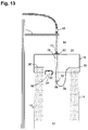
- the embodiment according to Figures 12 to 14 differs from the embodiments according to the previous Figures 4 to 10 by the lid 18 having an axially or vertically longer cylindrical wall 28.
- lid 18 In the position of the lid 18 according to Figure 12 , lid 18 is in the low or lower most position in which front wall 20 is close to upper edge 90 of the box sidewall 14. This position is the transport position of the container.
- lid 18 is raised in a raised position (see Figures 13 and 14 ) in which the front wall 20 is significantly distanced from upper edge 90 so that there is sufficient space for wire 34 to freely protrude into wire outlet guide 50.
- Box sidewall 14 has a U-cut 92 circumscribing a tongue 94 which integrally extends into the remainder of box sidewall 14 along a hinge portion 96.
- Tongue 94 can be pulled outwardly or, more precisely, pivoted outwardly so that tongue 94 defines a stop portion for lid 18 which is prevented from moving down to the position according to Figure 12 .
- the Figure 14 embodiment differs from the Figure 13 embodiment by the wire outlet guide 50 being arranged with respect to the front wall 20 so as to protrude significantly out from the container and to bridge the distance from the front wall to conduit 46.
- wire outlet guide 50 can be displaceable with respect to the front wall or can be permanently fixed and non-displaceable attached to front wall 20.
- holes 56 and 64 are in a fixed position during payoff of wire 34.
Landscapes
- Engineering & Computer Science (AREA)
- Mechanical Engineering (AREA)
- Physics & Mathematics (AREA)
- Plasma & Fusion (AREA)
- Packaging Of Annular Or Rod-Shaped Articles, Wearing Apparel, Cassettes, Or The Like (AREA)
- Unwinding Of Filamentary Materials (AREA)
Priority Applications (1)
| Application Number | Priority Date | Filing Date | Title |
|---|---|---|---|
| PL16180212T PL3141506T3 (pl) | 2015-09-10 | 2016-07-19 | Pokrywka pojemnika na drut, pojemnik na drut i układ podawania drutu |
Applications Claiming Priority (1)
| Application Number | Priority Date | Filing Date | Title |
|---|---|---|---|
| US14/850,753 US9975728B2 (en) | 2015-09-10 | 2015-09-10 | Wire container lid, wire container and wire feeding system |
Publications (2)
| Publication Number | Publication Date |
|---|---|
| EP3141506A1 true EP3141506A1 (de) | 2017-03-15 |
| EP3141506B1 EP3141506B1 (de) | 2018-09-26 |
Family
ID=56507412
Family Applications (1)
| Application Number | Title | Priority Date | Filing Date |
|---|---|---|---|
| EP16180212.9A Active EP3141506B1 (de) | 2015-09-10 | 2016-07-19 | Drahtbehälterdeckel, drahtbehälter und drahtzuführungssystem |
Country Status (5)
| Country | Link |
|---|---|
| US (1) | US9975728B2 (de) |
| EP (1) | EP3141506B1 (de) |
| ES (1) | ES2699913T3 (de) |
| HU (1) | HUE042215T2 (de) |
| PL (1) | PL3141506T3 (de) |
Cited By (3)
| Publication number | Priority date | Publication date | Assignee | Title |
|---|---|---|---|---|
| DE102017103792A1 (de) | 2017-02-23 | 2018-08-23 | R & L Furthmayr Gmbh | Vorrichtung und Verfahren zum Entnehmen und Fördern von Drähten |
| CN113213247A (zh) * | 2021-05-21 | 2021-08-06 | 菲翼汽车电气(上海)有限公司 | 一种导线上料机构、方法和送线设备 |
| WO2024173301A1 (en) * | 2023-02-13 | 2024-08-22 | Cerro Wire Llc | Barrel for storing conductors or wires |
Families Citing this family (7)
| Publication number | Priority date | Publication date | Assignee | Title |
|---|---|---|---|---|
| DE102015012728A1 (de) * | 2015-10-01 | 2017-04-06 | Alzchem Ag | Lager- und Transportcontainer für Fülldrähte |
| US10292545B2 (en) * | 2016-11-18 | 2019-05-21 | RD Textiles, LLC | Center-pull dispenser system |
| US11311958B1 (en) * | 2019-05-13 | 2022-04-26 | Airgas, Inc. | Digital welding and cutting efficiency analysis, process evaluation and response feedback system for process optimization |
| CN110294353A (zh) * | 2019-07-04 | 2019-10-01 | 江苏华兮网络科技工程有限公司 | 一种网络工程的具有自矫正保护封闭式的网线箱 |
| CN114084735B (zh) * | 2021-11-23 | 2023-03-14 | 中国人民解放军陆军工程大学 | 手持式放线装置 |
| US20230381881A1 (en) * | 2022-05-25 | 2023-11-30 | Illinois Tool Works Inc. | Systems and methods for dispensing welding wire to a spool gun |
| WO2024004240A1 (ja) * | 2022-06-30 | 2024-01-04 | 株式会社フジクラ | 梱包ユニット |
Citations (4)
| Publication number | Priority date | Publication date | Assignee | Title |
|---|---|---|---|---|
| US1936227A (en) * | 1932-01-08 | 1933-11-21 | C And W Wire Container Company | Wire container |
| EP0017445A1 (de) * | 1979-03-28 | 1980-10-15 | Geoffrey Edmund Whellams | Vorrichtung um einem Filament Spannung zu geben |
| US20070175965A1 (en) * | 2006-02-02 | 2007-08-02 | Lincoln Global, Inc. | System and method of providing endless welding wire |
| WO2009027784A2 (en) * | 2007-08-30 | 2009-03-05 | Lincoln Global, Inc. | Apparatus and method for tapered core drum package payoff |
Family Cites Families (310)
| Publication number | Priority date | Publication date | Assignee | Title |
|---|---|---|---|---|
| US1468994A (en) | 1923-09-25 | Spooled wire | ||
| US617353A (en) | 1899-01-10 | Wire-coiling device | ||
| US532565A (en) | 1895-01-15 | Rod-mill reel | ||
| US318062A (en) | 1885-05-19 | warren | ||
| US627722A (en) | 1897-08-25 | 1899-06-27 | Morgan Construction Co | Wire-reel. |
| DE152978C (de) | 1903-08-07 | |||
| US932808A (en) | 1909-04-17 | 1909-08-31 | Henry B Pelton | Paper-roll protector. |
| US1276117A (en) | 1917-06-13 | 1918-08-20 | Rogers Motor Lock Company | Flexible armored conduit. |
| US1508689A (en) | 1921-09-23 | 1924-09-16 | Gen Electric | Metallic arc welding |
| US1640368A (en) | 1926-12-13 | 1927-08-30 | Us Asbestos Company | Asbestos rope or wick package |
| US1821354A (en) | 1929-01-14 | 1931-09-01 | William H Meyer | Card mount for strings |
| US1907051A (en) | 1931-05-18 | 1933-05-02 | Wallace V Emery | Metallic welding electrode |
| US2078161A (en) | 1934-03-21 | 1937-04-20 | Gen Electric | Gearing |
| US2027670A (en) | 1934-09-17 | 1936-01-14 | Marathon Paper Mills Co | Paper dispenser |
| US2027674A (en) | 1935-08-28 | 1936-01-14 | Marathon Paper Mills Co | Dispenser for folded sheets |
| US2260230A (en) | 1939-08-16 | 1941-10-21 | Adrian A Olson | Container |
| US2319628A (en) | 1940-08-04 | 1943-05-18 | American Steel & Wire Co | Burner basket |
| US2329369A (en) | 1942-03-28 | 1943-09-14 | Ryan Aeronautical Company | Ball and socket joint |
| US2366101A (en) | 1943-08-18 | 1944-12-26 | Scott & Williams Inc | Yarn holding means |
| US2407746A (en) | 1944-12-02 | 1946-09-17 | Jesse E Johnson | Oscillating welding rod |
| US2457910A (en) | 1946-02-02 | 1949-01-04 | W L Maxson Corp | Flexible cable |
| US2483760A (en) | 1947-08-07 | 1949-10-04 | Sprinkle W Duncan | Electrical cable guide |
| US2477059A (en) | 1948-02-19 | 1949-07-26 | Deere Mfg Co | Dispensing mechanism for balers or the like |
| US2579131A (en) | 1948-12-10 | 1951-12-18 | Prec Steel Warehouse Inc | Dispensing container for coiled wire |
| US2580900A (en) | 1950-02-23 | 1952-01-01 | Mandel E Epstein | Package for twine, rope, or the like |
| US2713938A (en) | 1950-04-26 | 1955-07-26 | New Bedford Cordage Company | Rope package |
| US2694130A (en) | 1952-08-28 | 1954-11-09 | Posy A Howard | Arc welding wire guide |
| US2752108A (en) | 1952-08-28 | 1956-06-26 | Driscoll Wire Company | Shipping container and paying-off device |
| US2724538A (en) | 1952-09-10 | 1955-11-22 | Lewin Mathes Company | Packaging materials |
| US2679571A (en) | 1952-11-12 | 1954-05-25 | Utica Drop Forge & Tool Corp | Tip welder tool |
| US2849195A (en) | 1953-08-18 | 1958-08-26 | Driscoll Wire Company | Combination wire drawing and packaging device |
| US2974850A (en) | 1954-05-10 | 1961-03-14 | Owens Illinois Glass Co | Combined shipping container and dispensing receptacle |
| US2966258A (en) | 1955-03-01 | 1960-12-27 | Anaconda Wire & Cable Co | Packaging of wire |
| US2864565A (en) | 1955-03-07 | 1958-12-16 | Rea Magnet Wire Company Inc | Apparatus for dispensing wire |
| US2869719A (en) | 1955-08-17 | 1959-01-20 | Hubbard Spool Company | Wire processing and storage container |
| US2838922A (en) | 1955-09-07 | 1958-06-17 | Rosedale Knitting Company | Yarn control device |
| FR1146262A (fr) | 1956-03-24 | 1957-11-08 | Geoffrey-Delore Sa | Dispositif pour dévider en continu du fil à partir de fûts |
| US2984596A (en) | 1956-08-01 | 1961-05-16 | Minnesota Mining & Mfg | Label tape and method of applying same to a rubber article |
| US2880305A (en) | 1958-04-24 | 1959-03-31 | Union Carbide Corp | Welding wire feed |
| US2929576A (en) | 1958-08-25 | 1960-03-22 | Western Electric Co | Apparatus for distributing a strand into coil form |
| US3022415A (en) | 1958-07-16 | 1962-02-20 | Soudure Electr Autogene Sa | Gun and process for semi-automatic arc welding |
| GB880502A (en) | 1959-07-27 | 1961-10-25 | Vaughn Machinery Co | Wire packaging machine and method |
| US3028066A (en) | 1960-09-28 | 1962-04-03 | Ripon Foods Inc | Multiple section paperboard container |
| US3185185A (en) | 1961-01-04 | 1965-05-25 | Sobel Metal Products Inc | Wire shaping apparatus |
| US3108180A (en) | 1961-02-07 | 1963-10-22 | Pullmax Ab | Welding electrode mouthpiece |
| US3119042A (en) | 1961-03-14 | 1964-01-21 | Chemetron Corp | Apparatus and method for feeding fabricated welding wire |
| US3096951A (en) | 1962-01-02 | 1963-07-09 | New Haven Wire & Cable Inc | Wire package and reel therefor |
| US3244347A (en) | 1964-02-20 | 1966-04-05 | Mead Corp | Corner post construction |
| US3344682A (en) | 1964-04-16 | 1967-10-03 | American Chain & Cable Co | Roller bearing push-pull cable |
| US3274850A (en) | 1964-11-04 | 1966-09-27 | Nazarene F Tascio | Flexible push-pull control cable |
| US3283121A (en) | 1965-07-21 | 1966-11-01 | Bernard Welding Equip Co | Arc welding gun |
| US3284608A (en) | 1965-09-29 | 1966-11-08 | Ralph C Mcdonald | Cleaner device for welding nozzle |
| US3352412A (en) | 1965-12-01 | 1967-11-14 | Micro Miniature Parts Corp | Package for flexible material |
| US3433504A (en) | 1966-07-05 | 1969-03-18 | Ventura Tool Co | Flexible connectors |
| DE1499056A1 (de) | 1966-12-21 | 1969-10-02 | Kabel Metallwerke Ghh | Anordnung zur Verlegung von strangfoermigem Gut,insbesondere von elektrischen Leitungen oder Draehten,im Innern von Vorratsfaessern |
| FR1516082A (fr) | 1967-01-06 | 1968-03-08 | Quenot & Cie Sarl | Procédé de freinage d'un ruban métallique d'instrument de mesures linéaires et instrument de mesures linéaires comportant application de ce procédé |
| US3576966A (en) | 1967-03-27 | 1971-05-04 | Air Reduction | Arc-welding in narrow gap |
| GB1229913A (de) | 1967-07-27 | 1971-04-28 | ||
| US3478435A (en) | 1968-03-11 | 1969-11-18 | Edmond A Cook | Depth gauge for measuring the thickness of animal tissues |
| US3630425A (en) | 1968-04-20 | 1971-12-28 | Messer Griesheim Gmbh | Electrode wire advance for arc welding |
| US3567900A (en) | 1968-08-14 | 1971-03-02 | Battelle Development Corp | Welding method and apparatus |
| US3536888A (en) | 1968-08-15 | 1970-10-27 | Lawrence A Borneman | Splatter-free welding gun |
| US3491876A (en) | 1968-08-19 | 1970-01-27 | Hudson Wire Co | Wire package |
| US3565129A (en) | 1968-10-18 | 1971-02-23 | Manganese Steel Forge Co | Wire crimper |
| US3512635A (en) | 1968-10-31 | 1970-05-19 | Nat Standard Co | Wire let-off assembly wire coil package and combined wire coil package and let-off assembly |
| US3648920A (en) | 1968-11-20 | 1972-03-14 | Clevepak Corp | Tubular member |
| US3595277A (en) | 1969-07-07 | 1971-07-27 | Mckay Co | Wire straightener |
| US3586222A (en) | 1969-08-28 | 1971-06-22 | Air Reduction | Speed control system for multiple motor feed of welding wire |
| GB1302055A (de) | 1969-09-16 | 1973-01-04 | ||
| US3659737A (en) | 1970-01-08 | 1972-05-02 | Hermann K Garbe | Collapsible containers |
| US3690567A (en) | 1970-03-09 | 1972-09-12 | Lawrence A Borneman | Electric arc welding gun having a nozzle with a removable metal liner to protect the nozzle from weld splatter |
| US3672655A (en) | 1970-03-12 | 1972-06-27 | Kenneth G Carter | Wire feeder |
| US3724249A (en) | 1970-03-28 | 1973-04-03 | Kloeckner Werke Ag | Method of and device for the coiling of metal tape or strip |
| US3675499A (en) | 1970-09-18 | 1972-07-11 | Andre Marosy | Coupling |
| US3729092A (en) | 1971-03-12 | 1973-04-24 | W Marcell | Unwind support for coiled wire |
| BE791587A (fr) | 1971-11-19 | 1973-05-17 | Philips Nv | Dispositif d'entrainement et d'orientation d'un fil de soudage |
| US3815842A (en) | 1972-08-01 | 1974-06-11 | W Scrogin | Reel |
| US3823894A (en) | 1973-01-04 | 1974-07-16 | Anaconda Co | Strand package |
| US3939978A (en) | 1974-07-23 | 1976-02-24 | Ppg Industries, Inc. | Flat glass shipping container |
| SE7513076L (sv) | 1974-11-22 | 1976-05-24 | Hitachi Shipbuilding Eng Co | Bagsvetsningsmetod och anordning herfor |
| US3958712A (en) | 1975-02-07 | 1976-05-25 | The Martin Brothers | Storage and carriage bin |
| US4102483A (en) | 1975-03-13 | 1978-07-25 | Osaka Denki Co., Ltd. | Method for feeding a welding wire |
| US4000797A (en) | 1975-06-02 | 1977-01-04 | Paul Ducanis | Noise-absorbing bar stock guide for screw machine |
| DE2525938C3 (de) | 1975-06-11 | 1979-07-05 | Messer Griesheim Gmbh, 6000 Frankfurt | Rollenführung zum Umlenken eines Schweißdrahtes |
| US4188526A (en) | 1976-03-15 | 1980-02-12 | Babcock-Hitachi Kabushiki Kaisha | Narrow weld-groove welding process |
| US4044583A (en) | 1976-05-27 | 1977-08-30 | Wire Conveyor Belts, Inc. | Method and apparatus for making elongated flat wire coils |
| JPS53128195A (en) | 1977-04-15 | 1978-11-08 | Sanko Kaihatsu Kagaku Kenkiyuu | Flame retarder |
| US4097004A (en) | 1977-05-06 | 1978-06-27 | Ppg Industries, Inc. | Method and apparatus for unwinding roving packages from the inside |
| JPS5435842A (en) | 1977-08-26 | 1979-03-16 | Nippon Steel Welding Prod Eng | Method for connecting wires in automatic welder |
| JPS5443856A (en) | 1977-09-14 | 1979-04-06 | Kobe Steel Ltd | Method and apparatus for coiling wire |
| US4161248A (en) | 1977-10-17 | 1979-07-17 | Universal Wire & Cable Co. Ltd. | Container for wire spool |
| US4172375A (en) | 1978-04-28 | 1979-10-30 | Kennecott Copper Corporation | Coiling system for metallic strands |
| US4171783A (en) | 1978-05-12 | 1979-10-23 | Phelps Dodge Industries, Inc. | Filament dereeling apparatus |
| JPS5554295A (en) | 1978-10-13 | 1980-04-21 | Nippon Steel Weld Prod & Eng Co Ltd | Connecting method of wire for automatic welding |
| JPS55112176A (en) | 1979-02-19 | 1980-08-29 | Osaka Denki Kk | Method and device for controlling wire feeding |
| JPS55156694A (en) | 1979-05-25 | 1980-12-05 | Nippon Steel Weld Prod & Eng Co Ltd | Small-diameter wire filler for welding |
| US4222535A (en) | 1979-07-16 | 1980-09-16 | Mossberg Hubbard, Division Of Wanskuck Company | Wire dereeling apparatus |
| JPS5623376A (en) | 1979-08-01 | 1981-03-05 | Nippon Steel Weld Prod & Eng Co Ltd | Arc welding method |
| DE2939316A1 (de) | 1979-09-28 | 1981-04-16 | Lucke-Apparate-Bau GmbH, 7947 Mengen | Garnwickelkoerper (kuchen) sowie verfahren und vorrichtung zu seiner herstellung |
| US4274607A (en) | 1979-12-03 | 1981-06-23 | Belden Corporation | Guide device for use in elongate filament dispensing package and the like |
| US4293103A (en) | 1979-12-17 | 1981-10-06 | Kotaro Tsukamoto | Metal wire winding apparatus |
| SE446717B (sv) | 1980-05-21 | 1986-10-06 | Skaltek Ab | Forfarande for astadkommande av en spolstomme |
| JPS57102471A (en) | 1980-12-12 | 1982-06-25 | Sumikin Yousetsubou Kk | Method of winding welding wire |
| JPS57111904A (en) | 1980-12-27 | 1982-07-12 | Horiba Ltd | Flexible cable |
| CA1169390A (en) | 1980-12-29 | 1984-06-19 | Eiichiro Kawasaki | Welding wire container |
| US4575612A (en) | 1981-04-09 | 1986-03-11 | Robert Prunier | Arc welding guide tube with non-adhesive tip |
| JPS5835068A (ja) | 1981-08-27 | 1983-03-01 | Nippon Steel Weld Prod & Eng Co Ltd | 溶接用ワイヤの装填物 |
| GB2106816B (en) | 1981-10-05 | 1985-11-06 | Mitsubishi Heavy Ind Ltd | Narrow gap arc welding process and apparatus therefor |
| US4464919A (en) | 1981-12-09 | 1984-08-14 | Labbe Robert A | Wire straightener and method for straightening wire |
| US4392606A (en) | 1981-12-17 | 1983-07-12 | Westvaco Corporation | Pre-banded bulk pack container |
| US4531040A (en) | 1982-01-11 | 1985-07-23 | Mitsubishi Denki K.K. | Hot wire type arc welding torch and cable |
| US4516692A (en) | 1982-02-17 | 1985-05-14 | Williamette Industries, Inc. | Disposable container assembly for liquids or semi-liquids in bulk |
| JPS58188126U (ja) | 1982-06-08 | 1983-12-14 | 株式会社井上ジャパックス研究所 | ワイヤカツト放電加工装置 |
| US4451014A (en) | 1982-08-11 | 1984-05-29 | Mossberg Industries, Inc. | Wire storing and dereeling apparatus |
| EP0130191B1 (de) | 1982-12-30 | 1986-05-14 | Eurosteel S.A. | Fadenförmige elemente verwendbar zur verstärkung von giessfähigen materialien, insbesondere beton |
| US4546631A (en) | 1983-04-01 | 1985-10-15 | Foster Wheeler Energy Corporation | Roller mechanism for forming helical shapes |
| JPS59197386A (ja) | 1983-04-21 | 1984-11-08 | Matsushita Electric Ind Co Ltd | リ−ド線溶接用電極 |
| JPS59229287A (ja) | 1983-06-10 | 1984-12-22 | Nippon Steel Weld Prod & Eng Co Ltd | 溶接用ワイヤの装填物 |
| JPS59232669A (ja) | 1983-06-13 | 1984-12-27 | Kobe Steel Ltd | 溶接用ワイヤのキヤスト形成方法 |
| JPS6021181A (ja) | 1983-07-18 | 1985-02-02 | Mitsubishi Heavy Ind Ltd | 溶接ワイヤ−の屈曲方法 |
| US4540225A (en) | 1983-09-07 | 1985-09-10 | Arcair Company | Swivel cable coupling for an air carbon-arc cutting and gouging torch |
| JPS6082276A (ja) | 1983-10-06 | 1985-05-10 | Kobe Steel Ltd | パツク入り溶接用ワイヤのワイヤ継ぎ方法 |
| JPS6082275A (ja) | 1983-10-06 | 1985-05-10 | Kobe Steel Ltd | パツク入り溶接用ワイヤのワイヤ継ぎ方法 |
| JPS60184422A (ja) | 1984-02-29 | 1985-09-19 | Kobe Steel Ltd | 溶接用ワイヤのキヤスト形成方法 |
| JPS60223664A (ja) | 1984-04-20 | 1985-11-08 | Nippon Steel Weld Prod & Eng Co Ltd | 溶接用ワイヤの装填方法 |
| US4582198A (en) | 1985-02-19 | 1986-04-15 | Essex Group, Inc. | Wire shipping and dispensing package |
| US5215338A (en) | 1985-04-09 | 1993-06-01 | Tsubakimoto Chain Co. | Flexible supporting sheath for cables and the like |
| JPS61293674A (ja) | 1985-06-21 | 1986-12-24 | Toyota Motor Corp | ア−ク溶接機 |
| JPS629774A (ja) | 1985-07-09 | 1987-01-17 | Toyota Motor Corp | ア−ク溶接機 |
| JPS62111872A (ja) | 1985-11-11 | 1987-05-22 | Kobe Steel Ltd | 溶接用ワイヤの引出し方法 |
| US4623063A (en) | 1986-01-29 | 1986-11-18 | Balkin Michael L | Fibreboard container for coil material |
| FR2595674B1 (fr) | 1986-03-14 | 1989-03-03 | Senelonge Henri | Machine pour la realisation de bottes de fils sans torsion |
| FR2596360B1 (fr) | 1986-04-01 | 1989-02-17 | Sotralentz Sa | Conteneur sur palette avec dispositif de protection en treillis plie et renforce |
| JP2514932B2 (ja) | 1986-06-06 | 1996-07-10 | 株式会社古河テクノマテリアル | 形状記憶合金線材の直線形状記憶処理方法 |
| JPS63147781A (ja) | 1986-12-09 | 1988-06-20 | Kobe Steel Ltd | 溶接用パツクワイヤ |
| US4868366A (en) | 1986-12-16 | 1989-09-19 | Joseph Beresford C | Arc welding capable of multi-mode welding |
| GB8714578D0 (en) | 1987-06-22 | 1987-07-29 | British Telecomm | Fibre winding |
| FR2623432B1 (fr) | 1987-11-20 | 1990-04-20 | Framatome Sa | Dispositif de decoupage par etincelage de la paroi d'une piece tubulaire |
| JPH01240222A (ja) | 1988-03-19 | 1989-09-25 | Fanuc Ltd | ワイヤ回収箱 |
| US4949567A (en) | 1988-11-04 | 1990-08-21 | Corbin Edward W | Apparatus and method for control of wire cast and helix |
| US5227314A (en) | 1989-03-22 | 1993-07-13 | At&T Bell Laboratories | Method of making metal conductors having a mobile inn getterer therein |
| US4918286A (en) | 1989-05-01 | 1990-04-17 | Boyer Robert W | Method and apparatus for cleaning and lubricating a metal inert gas welding gun |
| US4974789A (en) | 1989-06-29 | 1990-12-04 | Trimedyne Laser Systems, Inc. | Dispensing package for a fiber-optic device |
| US5165217A (en) | 1989-09-12 | 1992-11-24 | Ethicon, Inc. | One piece channel suture packages |
| JPH03264169A (ja) | 1990-03-13 | 1991-11-25 | Daido Steel Co Ltd | 溶接ワイヤ収納容器 |
| US5078269A (en) | 1990-06-07 | 1992-01-07 | Group Dekko International, Inc. | Wire shipping and dispensing container |
| US5051539A (en) | 1990-06-07 | 1991-09-24 | Dave A. Leathers | Swivel joint for cover of fluid-cooled welding cable |
| JPH04112169A (ja) | 1990-08-29 | 1992-04-14 | Nippon Steel Weld Prod & Eng Co Ltd | 溶接用ワイヤの抑え部材 |
| JPH04133973A (ja) | 1990-09-21 | 1992-05-07 | Nippon Steel Weld Prod & Eng Co Ltd | 溶接用ワイヤ収納ペイルパック |
| US5097951A (en) | 1990-10-16 | 1992-03-24 | Nucon Corporation | Unit load assembly for spools |
| GB9100128D0 (en) | 1991-01-04 | 1991-02-20 | Fleming Stewart B | Golf trainer |
| US5109983A (en) | 1991-01-28 | 1992-05-05 | Minnesota Mining And Manufacturing Company | Package for an optical fiber jumper |
| JP2781669B2 (ja) | 1991-02-28 | 1998-07-30 | 日鐵溶接工業株式会社 | 溶接用ワイヤの装填方法 |
| US5105943A (en) | 1991-05-14 | 1992-04-21 | Sonoco Products Company | Wire coil package |
| CA2071419C (en) | 1991-06-18 | 1996-03-19 | William Dimmett Cooper | Retainer ring for welding wire container |
| US5314111A (en) | 1991-09-28 | 1994-05-24 | Kabushiki Kaisha Kobe Seiko Sho | Packaging box and sheet for packaging box |
| JP3155786B2 (ja) | 1991-10-11 | 2001-04-16 | 日立ビアメカニクス株式会社 | 半自動アーク溶接機 |
| JP2978612B2 (ja) | 1991-10-16 | 1999-11-15 | 株式会社山本製作所 | 梱包用の箱体 |
| JPH05178538A (ja) | 1991-12-27 | 1993-07-20 | Daido Steel Co Ltd | ペイルパック用引出し治具 |
| US5201419A (en) | 1992-02-21 | 1993-04-13 | Laclede Chain Manufacturing Company | Chain container |
| GB9204268D0 (en) | 1992-02-28 | 1992-04-08 | M Y Humberside Packaging Limit | Stackable container |
| US5205412A (en) | 1992-04-08 | 1993-04-27 | Aurex, S.A. De C.V. | Recyclable package for a stack of rolls of magnetic tape |
| US5372269A (en) | 1992-04-23 | 1994-12-13 | Creative Thermal Vac Manufacturing, Inc. | Multipurpose container and display sign |
| CA2068828C (en) | 1992-05-15 | 1998-12-22 | Michel Lanoue | Device for dispensing wire, cable or the like |
| AT397778B (de) | 1992-07-29 | 1994-06-27 | Boehler Schweisstechnik | Behältnis für schweissdraht |
| JPH06107377A (ja) | 1992-09-28 | 1994-04-19 | Bridgestone Bekaert Steel Code Kk | 金属線条体用リ−ル |
| US5279441A (en) | 1992-10-13 | 1994-01-18 | Featherall J Ronald | Waste material storage and baling bin |
| IT231566Y1 (it) | 1993-02-23 | 1999-08-04 | Sidergas Srl | Contenitore di imballaggio e di svolgimento di una matassa di filo metallico |
| US5368245A (en) | 1993-07-20 | 1994-11-29 | Communication Cable, Inc. | Two-piece pay-out tube |
| JP2783125B2 (ja) | 1993-07-23 | 1998-08-06 | 株式会社デンソー | ワイヤボンディング方法 |
| US5702001A (en) | 1994-08-17 | 1997-12-30 | The Moore Company | Container and method for relaxing snags during dispensement of strip material |
| GB9401604D0 (en) | 1994-01-27 | 1994-03-23 | Mitchell Packaging Limited | Containers and container systems |
| US5553810A (en) | 1994-02-23 | 1996-09-10 | The Lincoln Electric Company | Covers for welding wire reels |
| JPH07247058A (ja) | 1994-03-08 | 1995-09-26 | Kobe Steel Ltd | 溶接用ワイヤの装填物及び溶接ワイヤ用のペイル容器 |
| US5586733A (en) | 1994-07-21 | 1996-12-24 | Bridgestone Metalpha Corporation | Take-up reel for metallic filaments |
| JPH0840642A (ja) | 1994-07-27 | 1996-02-13 | Nippon Steel Weld Prod & Eng Co Ltd | 溶接用ワイヤの装填物 |
| JPH08150492A (ja) | 1994-11-24 | 1996-06-11 | Kawasaki Steel Corp | 溶接用ワイヤ |
| WO1996017701A1 (de) | 1994-12-07 | 1996-06-13 | Uwe Otzen | Verfahren und vorrichtung zur optimierten herstellung von schraubenfedern auf federwindeautomaten |
| JP2793970B2 (ja) | 1995-03-30 | 1998-09-03 | 株式会社神戸製鋼所 | エレクトロスラグ溶接用ワイヤ装填物 |
| US5585013A (en) | 1995-04-07 | 1996-12-17 | Truty; Thomas J. | Electrode guide |
| GB9602580D0 (en) | 1996-02-08 | 1996-04-10 | Dual Voltage Ltd | Plastics flexible core |
| KR0135931Y1 (ko) | 1996-03-20 | 1999-02-18 | 정몽석 | 용접용 와이어의 엉킴방지장치 |
| US5816466A (en) | 1996-04-19 | 1998-10-06 | The Lincoln Electric Company | Wire feeding apparatus |
| IT1286954B1 (it) | 1996-07-24 | 1998-07-24 | C I F E S P A | Dispositivo per la frenatura dello svolgimento di filo metallico in matassa alloggiato in fusto |
| USRE40351E1 (en) | 1996-07-24 | 2008-06-03 | Lincoln Global, Inc. | Mechanism for braking the unwinding of a bundle of metallic wire housed in a drum |
| US5758834A (en) | 1996-08-20 | 1998-06-02 | Illinois Tool Works Inc. | Welding wire storage and shipping container |
| US5738209A (en) | 1996-12-23 | 1998-04-14 | General Motors Corporation | Cable storage container |
| CA2194937A1 (en) | 1997-01-13 | 1998-07-13 | John Craig | Mobile automated pipeline welding and quality control system |
| WO1998052844A1 (en) | 1997-05-20 | 1998-11-26 | Esab Ab | Container for packaging and unwinding a coil of welding wire |
| US5988370A (en) | 1997-06-23 | 1999-11-23 | Roemer; Donald A. | Corrugated fibreboard container with at least one hinged side and blanks for assembling said container |
| JP3045774U (ja) | 1997-07-30 | 1998-02-13 | 金井 宏之 | 金属線条体巻装用リール |
| US5819934A (en) | 1997-10-27 | 1998-10-13 | The Lincoln Electric Company | Wire transport drum |
| US6072101A (en) | 1997-11-19 | 2000-06-06 | Amcol International Corporation | Multicomponent superabsorbent gel particles |
| US5921391A (en) | 1997-11-26 | 1999-07-13 | Stone Container Corporation | Container for storing and transporting wire, cord and the like |
| CN1095801C (zh) | 1998-01-29 | 2002-12-11 | 日铁溶接工业株式会社 | 焊接用焊丝的包装物 |
| US5971308A (en) | 1998-03-04 | 1999-10-26 | National-Standard Company | Wire transfer assembly |
| AT409239B (de) | 1998-05-13 | 2002-06-25 | Fronius Schweissmasch | Verfahren zum steuern eines schweissgerätes und steuervorrichtung hierfür |
| GB2332451A (en) | 1998-06-05 | 1999-06-23 | Welding Supplies | Delivery guide for wire |
| US6019303A (en) | 1998-12-16 | 2000-02-01 | Lincoln Global, Inc. | Method and apparatus for packing wire in a storage drum |
| JP2000202630A (ja) | 1999-01-13 | 2000-07-25 | Daido Steel Co Ltd | 溶接ワイヤ充填ペイル |
| JP2000225468A (ja) | 1999-02-04 | 2000-08-15 | Daido Steel Co Ltd | 溶接ワイヤ充填ペイル |
| US6016911A (en) | 1999-02-19 | 2000-01-25 | Chen; Hua-Mei | Package for a reel of wire |
| JP3071774B1 (ja) | 1999-02-25 | 2000-07-31 | 高麗溶接棒ジャパン株式会社 | 送給性の優れた溶接用ソリッドワイヤ |
| JP4154064B2 (ja) | 1999-03-16 | 2008-09-24 | 株式会社東芝 | マグネトロン部品の製造方法 |
| ES2203052T3 (es) | 1999-05-31 | 2004-04-01 | C.I.F.E. S.R.L. | Caja de carton para contener y distribuir hilo. |
| US6150632A (en) | 1999-06-10 | 2000-11-21 | Tregaskiss, Ltd. | Electronic lock-on wire feed switch device |
| US6247664B1 (en) | 1999-06-25 | 2001-06-19 | Siecor Operations, Llc | Reel monitor devices and methods of using the same |
| US6236017B1 (en) | 1999-07-01 | 2001-05-22 | Bechtel Bwxt Idaho, Llc | Method and apparatus for assessing weld quality |
| JP3723381B2 (ja) | 1999-07-15 | 2005-12-07 | 株式会社神戸製鋼所 | ペイル容器入り金属線材の収納方法 |
| DE19933901A1 (de) | 1999-07-22 | 2001-02-01 | Clariant Gmbh | Flammschutzmittel-Kombination |
| US6301944B1 (en) | 1999-09-22 | 2001-10-16 | General Electric Company | Methods of fabricating mechanized welding wire |
| KR100343927B1 (ko) | 1999-10-28 | 2002-07-19 | 주식회사 효성 | 스틸코드 권취용 스풀 |
| AT411032B (de) | 1999-11-19 | 2003-09-25 | Fronius Schweissmasch Prod | Verfahren und vorrichtung zum überwachen einer förderkraft |
| US6800056B2 (en) | 2000-04-03 | 2004-10-05 | Neoguide Systems, Inc. | Endoscope with guiding apparatus |
| US6296118B1 (en) | 2000-06-07 | 2001-10-02 | John W. Speck | Stackable, nestable, and reusable container for storing and dispensing elongated materials, and method of using same |
| KR100359482B1 (ko) | 2000-06-28 | 2002-10-31 | 고려용접봉 주식회사 | 송급성이 우수한 아크용접용 와이어 및 와이어의 신선방법 |
| US6409116B1 (en) | 2000-10-30 | 2002-06-25 | Maurice H. Brown | Rapidly adjustable wire control mechanism |
| US6530511B2 (en) | 2001-02-13 | 2003-03-11 | Medallion Technology, Llc | Wire feed mechanism and method used for fabricating electrical connectors |
| SE518955C2 (sv) | 2001-05-17 | 2002-12-10 | Metso Paper Inc | Anordning och sätt att haspla av tråd från en trådspole |
| SE0101749L (sv) | 2001-05-18 | 2002-04-23 | Esab Ab | Anordning vid svetstrådsmatning, trådorienteringslöpare, metod och användning |
| US6708864B2 (en) | 2001-06-15 | 2004-03-23 | Lincoln Global, Inc. | “S” shaped cast in wire |
| US6464077B1 (en) | 2001-07-06 | 2002-10-15 | Faithful Engineering Products Co., Ltd. | Container for thread and wire |
| US6636776B1 (en) | 2001-07-09 | 2003-10-21 | Lincoln Global, Inc. | System and method for managing welding procedures and welding resources |
| US6564943B2 (en) | 2001-07-13 | 2003-05-20 | Lincoln Global, Inc. | Container for welding wire |
| JP3812381B2 (ja) | 2001-07-30 | 2006-08-23 | 松下電器産業株式会社 | 溶接ワイヤ送給装置 |
| US6649870B1 (en) | 2001-08-31 | 2003-11-18 | Lincoln Global, Inc. | System and method facilitating fillet weld performance |
| US6648141B2 (en) | 2001-09-04 | 2003-11-18 | Lincoln Global, Inc. | Packaging for containing and dispensing large quantities of wire |
| ITTO20010894A1 (it) | 2001-09-19 | 2003-03-19 | Sidergas Srl | Contenitore di un filo per saldatura. |
| US6715608B1 (en) | 2001-11-06 | 2004-04-06 | Lincoln Global, Inc. | Package for welding wire |
| US6745899B1 (en) | 2002-02-25 | 2004-06-08 | Lincoln Global, Inc. | Wire payout |
| US7156334B1 (en) | 2002-03-01 | 2007-01-02 | X-Spooler, Inc. | Pay-out tube |
| US6648376B2 (en) | 2002-03-29 | 2003-11-18 | Showertek, Inc. | Flexible sectioned arm with internal overbending-prevention sleeves |
| US7017742B2 (en) | 2002-04-10 | 2006-03-28 | Hobart Brothers Company, | Recyclable container adapted for movement by a lifting device and method for making same |
| ITMI20020898A1 (it) * | 2002-04-24 | 2003-10-24 | Isaf S P A | Contenitore per matassa di filo per saldatura dotabile di dispositivoper collegare allo stesso una guaina di alimentazione del filo ad una |
| US6547176B1 (en) | 2002-06-04 | 2003-04-15 | Air Liquide Canada Inc. | Wire unwinding controller |
| US7441721B2 (en) | 2002-06-17 | 2008-10-28 | Hyundai Welding Co., Ltd. | Device for preventing welding wire from tangling |
| JP2004025242A (ja) | 2002-06-26 | 2004-01-29 | Nippon Steel & Sumikin Welding Co Ltd | ガスシールドアーク溶接用ワイヤ |
| JP2004025243A (ja) | 2002-06-26 | 2004-01-29 | Nippon Steel & Sumikin Welding Co Ltd | 溶接用ワイヤの送給方法 |
| KR100443728B1 (ko) | 2002-09-07 | 2004-08-09 | 박종근 | 용접용 와이어 패일팩에 설치되는 누름판 |
| KR100836614B1 (ko) | 2002-12-30 | 2008-06-10 | 현대종합금속 주식회사 | 용접용 와이어 엉킴 방지장치 |
| US6913145B2 (en) | 2003-04-15 | 2005-07-05 | Lincoln Global, Inc. | Welding wire container with ribbed walls and a mating retainer ring |
| CN1788053A (zh) | 2003-04-17 | 2006-06-14 | 互应化学工业株式会社 | 阻燃环氧树脂组合物、包含该组合物的预浸料、层压体和印制线路板 |
| US20040211851A1 (en) | 2003-04-24 | 2004-10-28 | Lincoln Global , Inc. | Welding wire payout drum |
| US6977357B2 (en) | 2003-07-09 | 2005-12-20 | Lincoln Global, Inc. | Welding wire positioning system |
| US7178755B2 (en) | 2003-07-30 | 2007-02-20 | Lincoln Global, Inc | Retainer ring for wire package |
| US7533906B2 (en) | 2003-10-14 | 2009-05-19 | Water Pik, Inc. | Rotatable and pivotable connector |
| AT500755B8 (de) | 2003-10-23 | 2007-02-15 | Fronius Int Gmbh | Drahtförderung mit konstantem moment |
| KR100560824B1 (ko) | 2003-12-12 | 2006-03-13 | 고려용접봉 주식회사 | 재활용이 가능한 용접 와이어용 페일팩 |
| DE10360466A1 (de) | 2003-12-22 | 2005-07-14 | Sidergas Spa | Abdeckung für einen Schweißdrahtbehälter |
| US9579742B2 (en) | 2006-01-09 | 2017-02-28 | Lincoln Global, Inc. | Series arc welder |
| AT413659B (de) | 2004-01-26 | 2006-04-15 | Fronius Int Gmbh | Schweissdraht-speichervorrichtung |
| US8225977B2 (en) | 2004-03-08 | 2012-07-24 | Lincoln Global, Inc. | Wire feeder with run-in control |
| US8592724B2 (en) | 2004-04-16 | 2013-11-26 | Illinois Tool Works Inc. | Remote wire feeder using binary phase shift keying to modulate communications of command/control signals to be transmitted over a weld cable |
| US7191968B2 (en) * | 2004-05-19 | 2007-03-20 | National Standard Company | System for handling welding wire and method of handling welding wire using the system |
| US7339135B2 (en) | 2004-06-04 | 2008-03-04 | Illinois Tool Works Inc. | Welding arc stabilization process |
| US20060070987A1 (en) | 2004-09-30 | 2006-04-06 | Lincoln Global, Inc. | Monitoring device for welding wire supply |
| US7220942B2 (en) | 2004-09-30 | 2007-05-22 | Lincoln Global, Inc. | Feeder for endless welding wire |
| US7377388B2 (en) | 2004-11-15 | 2008-05-27 | Lincoln Global, Inc. | Welding wire package |
| US7700893B2 (en) | 2004-12-22 | 2010-04-20 | Illinois Tool Works Inc. | System and method for calibrating wire feeder motor control |
| US20060138116A1 (en) | 2004-12-27 | 2006-06-29 | Lincoln Global, Inc. | Thread control for welding wire |
| NL1028049C2 (nl) | 2005-01-17 | 2006-07-18 | Marcel Francesco De Keizer | Draadgeleider. |
| US7301124B2 (en) | 2005-01-26 | 2007-11-27 | Illinois Tool Works Inc. | System and method for coordinating wire feeder motor operation |
| DE102005010016A1 (de) | 2005-03-04 | 2006-09-07 | Sidergas Spa | Niederhalter für einen Schweißdrahtbehälter |
| US20060196794A1 (en) | 2005-03-07 | 2006-09-07 | Lincoln Global, Inc. | Welding wire container and method of making the same |
| US20060207981A1 (en) | 2005-03-18 | 2006-09-21 | Lincoln Global, Inc., A Delaware Corporation | Interchangeable wire drive for wire feeder and spool gun |
| DE102005018566A1 (de) | 2005-04-21 | 2006-10-26 | Sidergas Spa | Abdeckung für einen Schweißdrahtbehälter |
| JP2007029971A (ja) | 2005-07-25 | 2007-02-08 | Kobe Steel Ltd | 溶接ワイヤ収納容器及び容器入り溶接ワイヤ |
| US7309038B2 (en) | 2005-05-27 | 2007-12-18 | Lincoln Global, Inc. | Endless wire container and method of using the same |
| FR2888825B1 (fr) | 2005-07-22 | 2007-10-19 | Neos Entpr Unipersonnelle A Re | Gaine pour le guidage d'un fil |
| ITTO20050591A1 (it) | 2005-08-29 | 2007-02-28 | Sidergas Srl | Elemento di rinforzo per un contenitore di filo per saldatura |
| US7398881B2 (en) | 2005-09-08 | 2008-07-15 | Lincoln Global, Inc. | Retainer ring for a wire package and method of making the same |
| EP1762819A1 (de) | 2005-09-12 | 2007-03-14 | Linde Aktiengesellschaft | Drahtvorschubmessgerät |
| US8245846B2 (en) | 2006-02-02 | 2012-08-21 | Lincoln Global, Inc. | Box for welding wire |
| DE102006022841A1 (de) | 2006-03-30 | 2007-10-04 | Sidergas Spa | Halterung für eine Schweißdrahtspule |
| US8637788B2 (en) | 2006-06-09 | 2014-01-28 | Victor Equipment Company | Flexible conductor tube for a welding gun |
| US7410111B2 (en) | 2006-06-16 | 2008-08-12 | Lincoln Global, Inc. | Guide ring for coiled wire |
| US9095929B2 (en) | 2006-07-14 | 2015-08-04 | Lincoln Global, Inc. | Dual fillet welding methods and systems |
| US20110132880A1 (en) | 2006-09-26 | 2011-06-09 | Barry Kossowan | Apparatus for Coating a Pipe Surface |
| KR100853528B1 (ko) | 2006-12-13 | 2008-08-21 | 고려용접봉 주식회사 | 용접 와이어용 페일팩 |
| US20080156925A1 (en) | 2007-01-03 | 2008-07-03 | Elco Enterprises, Inc. | Wire Dispensing System |
| DE102007015946A1 (de) | 2007-03-27 | 2008-10-02 | Sidergas Spa | Flexible Führung für einen Schweißdraht |
| US8629373B2 (en) | 2007-04-19 | 2014-01-14 | Illinois Tool Works Inc. | Synchronized multiple drive wire feed welding system and method |
| US9061366B2 (en) | 2007-06-22 | 2015-06-23 | Illinois Tool Works Inc. | Welding system and method having controlled liner contour and welding wire curvature |
| US7690593B2 (en) | 2007-07-09 | 2010-04-06 | Lincoln Global, Inc. | Welding wire guide ring |
| US7721985B2 (en) | 2007-07-09 | 2010-05-25 | Lincoln Global, Inc. | Welding wire guide ring |
| JP5001917B2 (ja) | 2008-03-31 | 2012-08-15 | 株式会社神戸製鋼所 | ワイヤ送給装置 |
| EP2288469B1 (de) | 2008-05-27 | 2013-04-10 | AWDS Technologies SRL | Drahtführungssystem |
| EP2168706A1 (de) | 2008-09-29 | 2010-03-31 | SIDERGAS Spa | Halter für einen Schweißdrahtbehälter mit flexiblen Klappen; Kombination von Schweissdrahtbund und einem solchen Halter |
| US8235210B2 (en) | 2009-04-27 | 2012-08-07 | Lincoln Global, Inc. | Welding wire container cover and container containing same |
| EP2256064A1 (de) | 2009-05-27 | 2010-12-01 | ISAF S.p.A. | Behälter für Schweißdraht mit verlängerten Elementen zum Halten der Drahtspule |
| US8235211B2 (en) | 2009-08-21 | 2012-08-07 | Sidergas Spa | Retainer for welding wire container, having fingers and half-moon shaped holding tabs |
| US20110042355A1 (en) | 2009-08-21 | 2011-02-24 | Carlo Gelmetti | Feeding system for a welding wire for a submerged welding process |
| US8127923B2 (en) | 2009-11-13 | 2012-03-06 | Sidergas Spa | Container for welding wire |
| US20110114617A1 (en) | 2009-11-13 | 2011-05-19 | Carlo Gelmetti | Liner, in particular for welding wire |
| EP2354039A1 (de) | 2010-01-27 | 2011-08-10 | Oerlikon Schweisstechnik GmbH | Behälter für Schweißdraht mit interner Halterung |
| US8389901B1 (en) | 2010-05-27 | 2013-03-05 | Awds Technologies Srl | Welding wire guiding liner |
| US20120160819A1 (en) | 2010-12-23 | 2012-06-28 | Lincoln Global, Inc. | Wire feed speed measurement device |
| EP2484476A1 (de) | 2011-02-04 | 2012-08-08 | SIDERGAS SpA | Schweißdrahtring und Behälter mit einem Schweißdrahtring |
| CN202240091U (zh) | 2011-03-14 | 2012-05-30 | 哈尔滨威德焊接自动化系统工程有限公司 | 辅助送丝装置 |
| KR20140090091A (ko) | 2011-05-23 | 2014-07-16 | 에이제트제트 더블유에스아이 엘엘씨 | 와이어 진동기를 포함하는 용접 장치 |
| DE202011104120U1 (de) | 2011-08-05 | 2011-11-21 | Awds Technologies S.R.L. | Drahtführung, insbesondere zur Führung von Schweißdraht |
| US9403231B2 (en) | 2011-11-09 | 2016-08-02 | Illinois Tool Works Inc. | Hybrid pulsed-short circuit welding regime |
| US9260269B2 (en) | 2011-11-22 | 2016-02-16 | Lincoln Global, Inc. | Wire retaining ring for a welding system |
| US9414759B2 (en) | 2011-12-06 | 2016-08-16 | Imris Inc. | Surface electrode design that can be left in place during MR imaging |
| US8882018B2 (en) | 2011-12-19 | 2014-11-11 | Sidergas Spa | Retainer for welding wire container and welding wire container with retainer |
| US8803034B2 (en) | 2012-01-17 | 2014-08-12 | Lincoln Global, Inc. | Systems and methods to feed wire within a welder |
| US20130200055A1 (en) | 2012-02-02 | 2013-08-08 | Lincoln Global, Inc. | Power source and wire feeder matching |
| EP2695696B1 (de) | 2012-08-09 | 2017-03-15 | AWDS Technologies SRL | Leitung zum Führen eines Drahtes, insbesondere eines Schweißdrahtes, mit zwei unterschiedlichen Körpern |
| JP5813702B2 (ja) | 2012-12-12 | 2015-11-17 | 株式会社国盛化学 | コンテナ |
| US10343231B2 (en) | 2014-05-28 | 2019-07-09 | Awds Technologies Srl | Wire feeding system |
-
2015
- 2015-09-10 US US14/850,753 patent/US9975728B2/en active Active
-
2016
- 2016-07-19 ES ES16180212T patent/ES2699913T3/es active Active
- 2016-07-19 HU HUE16180212A patent/HUE042215T2/hu unknown
- 2016-07-19 PL PL16180212T patent/PL3141506T3/pl unknown
- 2016-07-19 EP EP16180212.9A patent/EP3141506B1/de active Active
Patent Citations (4)
| Publication number | Priority date | Publication date | Assignee | Title |
|---|---|---|---|---|
| US1936227A (en) * | 1932-01-08 | 1933-11-21 | C And W Wire Container Company | Wire container |
| EP0017445A1 (de) * | 1979-03-28 | 1980-10-15 | Geoffrey Edmund Whellams | Vorrichtung um einem Filament Spannung zu geben |
| US20070175965A1 (en) * | 2006-02-02 | 2007-08-02 | Lincoln Global, Inc. | System and method of providing endless welding wire |
| WO2009027784A2 (en) * | 2007-08-30 | 2009-03-05 | Lincoln Global, Inc. | Apparatus and method for tapered core drum package payoff |
Cited By (3)
| Publication number | Priority date | Publication date | Assignee | Title |
|---|---|---|---|---|
| DE102017103792A1 (de) | 2017-02-23 | 2018-08-23 | R & L Furthmayr Gmbh | Vorrichtung und Verfahren zum Entnehmen und Fördern von Drähten |
| CN113213247A (zh) * | 2021-05-21 | 2021-08-06 | 菲翼汽车电气(上海)有限公司 | 一种导线上料机构、方法和送线设备 |
| WO2024173301A1 (en) * | 2023-02-13 | 2024-08-22 | Cerro Wire Llc | Barrel for storing conductors or wires |
Also Published As
| Publication number | Publication date |
|---|---|
| US9975728B2 (en) | 2018-05-22 |
| ES2699913T3 (es) | 2019-02-13 |
| PL3141506T3 (pl) | 2019-03-29 |
| US20170073180A1 (en) | 2017-03-16 |
| HUE042215T2 (hu) | 2019-06-28 |
| EP3141506B1 (de) | 2018-09-26 |
Similar Documents
| Publication | Publication Date | Title |
|---|---|---|
| US9975728B2 (en) | Wire container lid, wire container and wire feeding system | |
| US6745899B1 (en) | Wire payout | |
| EP0519424B1 (de) | Rückhalte-Ring für einen Schweissdrahtbehälter | |
| US8936210B2 (en) | Floating dispensing mechanism for drum packed welding wire | |
| EP1712021B1 (de) | Floating-auskleidung | |
| US9260269B2 (en) | Wire retaining ring for a welding system | |
| US20050194278A1 (en) | Welding wire container with ribbed walls and a mating retainer ring | |
| US7004419B2 (en) | Apparatus for packing wire in a storage container by use of reverse winding | |
| CN104603039B (zh) | 用于焊接系统的焊丝保持环 | |
| EP2354039A1 (de) | Behälter für Schweißdraht mit interner Halterung | |
| CN102574656B (zh) | 纱线卷绕装置 | |
| US8967520B2 (en) | Wire retaining ring for a welding system | |
| US8752782B2 (en) | Wire retaining ring for endless bulk mig wire boxes | |
| US20140183294A1 (en) | Wire control strip for a welding system | |
| EP2612833A1 (de) | Schweißdrahtbehälter mit einem vom Draht durchquerten gleitenden Gewichtselement | |
| CN202754629U (zh) | 自动络纱机的纱线退绕辅助装置及具备该装置的卷绕装置 | |
| US12466691B2 (en) | Kink prevention jig and pail pack | |
| US20190100402A1 (en) | Apparatus and method for reducing whip damage on wound optical fiber | |
| US3692254A (en) | Strand guiding apparatus | |
| KR101980412B1 (ko) | 용접 시스템용 와이어 유지 링 | |
| MX2011013623A (es) | Metodo y recipiente para alimentar continuamente alambre de soldadura a una maquina de soldar. | |
| US20050133657A1 (en) | Transport of a wrapping-paper web in the tobacco industry | |
| EP3554736A1 (de) | Drahtformvorrichtung für lose verpackten schweissdraht |
Legal Events
| Date | Code | Title | Description |
|---|---|---|---|
| PUAI | Public reference made under article 153(3) epc to a published international application that has entered the european phase |
Free format text: ORIGINAL CODE: 0009012 |
|
| STAA | Information on the status of an ep patent application or granted ep patent |
Free format text: STATUS: THE APPLICATION HAS BEEN PUBLISHED |
|
| AK | Designated contracting states |
Kind code of ref document: A1 Designated state(s): AL AT BE BG CH CY CZ DE DK EE ES FI FR GB GR HR HU IE IS IT LI LT LU LV MC MK MT NL NO PL PT RO RS SE SI SK SM TR |
|
| AX | Request for extension of the european patent |
Extension state: BA ME |
|
| STAA | Information on the status of an ep patent application or granted ep patent |
Free format text: STATUS: REQUEST FOR EXAMINATION WAS MADE |
|
| 17P | Request for examination filed |
Effective date: 20170822 |
|
| RBV | Designated contracting states (corrected) |
Designated state(s): AL AT BE BG CH CY CZ DE DK EE ES FI FR GB GR HR HU IE IS IT LI LT LU LV MC MK MT NL NO PL PT RO RS SE SI SK SM TR |
|
| GRAP | Despatch of communication of intention to grant a patent |
Free format text: ORIGINAL CODE: EPIDOSNIGR1 |
|
| STAA | Information on the status of an ep patent application or granted ep patent |
Free format text: STATUS: GRANT OF PATENT IS INTENDED |
|
| RIC1 | Information provided on ipc code assigned before grant |
Ipc: B23K 9/133 20060101ALI20180327BHEP Ipc: B65H 57/18 20060101ALI20180327BHEP Ipc: B65H 49/08 20060101AFI20180327BHEP Ipc: B65H 57/12 20060101ALI20180327BHEP |
|
| INTG | Intention to grant announced |
Effective date: 20180425 |
|
| GRAS | Grant fee paid |
Free format text: ORIGINAL CODE: EPIDOSNIGR3 |
|
| GRAA | (expected) grant |
Free format text: ORIGINAL CODE: 0009210 |
|
| STAA | Information on the status of an ep patent application or granted ep patent |
Free format text: STATUS: THE PATENT HAS BEEN GRANTED |
|
| AK | Designated contracting states |
Kind code of ref document: B1 Designated state(s): AL AT BE BG CH CY CZ DE DK EE ES FI FR GB GR HR HU IE IS IT LI LT LU LV MC MK MT NL NO PL PT RO RS SE SI SK SM TR |
|
| REG | Reference to a national code |
Ref country code: GB Ref legal event code: FG4D |
|
| REG | Reference to a national code |
Ref country code: CH Ref legal event code: EP |
|
| REG | Reference to a national code |
Ref country code: AT Ref legal event code: REF Ref document number: 1045755 Country of ref document: AT Kind code of ref document: T Effective date: 20181015 |
|
| REG | Reference to a national code |
Ref country code: IE Ref legal event code: FG4D |
|
| REG | Reference to a national code |
Ref country code: DE Ref legal event code: R096 Ref document number: 602016005934 Country of ref document: DE |
|
| REG | Reference to a national code |
Ref country code: SE Ref legal event code: TRGR |
|
| REG | Reference to a national code |
Ref country code: NL Ref legal event code: FP |
|
| REG | Reference to a national code |
Ref country code: CH Ref legal event code: NV Representative=s name: BUGNION S.A., CH |
|
| PG25 | Lapsed in a contracting state [announced via postgrant information from national office to epo] |
Ref country code: FI Free format text: LAPSE BECAUSE OF FAILURE TO SUBMIT A TRANSLATION OF THE DESCRIPTION OR TO PAY THE FEE WITHIN THE PRESCRIBED TIME-LIMIT Effective date: 20180926 Ref country code: GR Free format text: LAPSE BECAUSE OF FAILURE TO SUBMIT A TRANSLATION OF THE DESCRIPTION OR TO PAY THE FEE WITHIN THE PRESCRIBED TIME-LIMIT Effective date: 20181227 Ref country code: BG Free format text: LAPSE BECAUSE OF FAILURE TO SUBMIT A TRANSLATION OF THE DESCRIPTION OR TO PAY THE FEE WITHIN THE PRESCRIBED TIME-LIMIT Effective date: 20181226 Ref country code: NO Free format text: LAPSE BECAUSE OF FAILURE TO SUBMIT A TRANSLATION OF THE DESCRIPTION OR TO PAY THE FEE WITHIN THE PRESCRIBED TIME-LIMIT Effective date: 20181226 Ref country code: RS Free format text: LAPSE BECAUSE OF FAILURE TO SUBMIT A TRANSLATION OF THE DESCRIPTION OR TO PAY THE FEE WITHIN THE PRESCRIBED TIME-LIMIT Effective date: 20180926 Ref country code: LT Free format text: LAPSE BECAUSE OF FAILURE TO SUBMIT A TRANSLATION OF THE DESCRIPTION OR TO PAY THE FEE WITHIN THE PRESCRIBED TIME-LIMIT Effective date: 20180926 |
|
| REG | Reference to a national code |
Ref country code: LT Ref legal event code: MG4D |
|
| REG | Reference to a national code |
Ref country code: ES Ref legal event code: FG2A Ref document number: 2699913 Country of ref document: ES Kind code of ref document: T3 Effective date: 20190213 |
|
| PG25 | Lapsed in a contracting state [announced via postgrant information from national office to epo] |
Ref country code: AL Free format text: LAPSE BECAUSE OF FAILURE TO SUBMIT A TRANSLATION OF THE DESCRIPTION OR TO PAY THE FEE WITHIN THE PRESCRIBED TIME-LIMIT Effective date: 20180926 Ref country code: LV Free format text: LAPSE BECAUSE OF FAILURE TO SUBMIT A TRANSLATION OF THE DESCRIPTION OR TO PAY THE FEE WITHIN THE PRESCRIBED TIME-LIMIT Effective date: 20180926 Ref country code: HR Free format text: LAPSE BECAUSE OF FAILURE TO SUBMIT A TRANSLATION OF THE DESCRIPTION OR TO PAY THE FEE WITHIN THE PRESCRIBED TIME-LIMIT Effective date: 20180926 |
|
| REG | Reference to a national code |
Ref country code: SK Ref legal event code: T3 Ref document number: E 29429 Country of ref document: SK |
|
| PG25 | Lapsed in a contracting state [announced via postgrant information from national office to epo] |
Ref country code: RO Free format text: LAPSE BECAUSE OF FAILURE TO SUBMIT A TRANSLATION OF THE DESCRIPTION OR TO PAY THE FEE WITHIN THE PRESCRIBED TIME-LIMIT Effective date: 20180926 Ref country code: IS Free format text: LAPSE BECAUSE OF FAILURE TO SUBMIT A TRANSLATION OF THE DESCRIPTION OR TO PAY THE FEE WITHIN THE PRESCRIBED TIME-LIMIT Effective date: 20190126 Ref country code: EE Free format text: LAPSE BECAUSE OF FAILURE TO SUBMIT A TRANSLATION OF THE DESCRIPTION OR TO PAY THE FEE WITHIN THE PRESCRIBED TIME-LIMIT Effective date: 20180926 |
|
| PG25 | Lapsed in a contracting state [announced via postgrant information from national office to epo] |
Ref country code: PT Free format text: LAPSE BECAUSE OF FAILURE TO SUBMIT A TRANSLATION OF THE DESCRIPTION OR TO PAY THE FEE WITHIN THE PRESCRIBED TIME-LIMIT Effective date: 20190126 Ref country code: SM Free format text: LAPSE BECAUSE OF FAILURE TO SUBMIT A TRANSLATION OF THE DESCRIPTION OR TO PAY THE FEE WITHIN THE PRESCRIBED TIME-LIMIT Effective date: 20180926 |
|
| REG | Reference to a national code |
Ref country code: DE Ref legal event code: R097 Ref document number: 602016005934 Country of ref document: DE |
|
| REG | Reference to a national code |
Ref country code: HU Ref legal event code: AG4A Ref document number: E042215 Country of ref document: HU |
|
| PG25 | Lapsed in a contracting state [announced via postgrant information from national office to epo] |
Ref country code: DK Free format text: LAPSE BECAUSE OF FAILURE TO SUBMIT A TRANSLATION OF THE DESCRIPTION OR TO PAY THE FEE WITHIN THE PRESCRIBED TIME-LIMIT Effective date: 20180926 |
|
| PLBE | No opposition filed within time limit |
Free format text: ORIGINAL CODE: 0009261 |
|
| STAA | Information on the status of an ep patent application or granted ep patent |
Free format text: STATUS: NO OPPOSITION FILED WITHIN TIME LIMIT |
|
| 26N | No opposition filed |
Effective date: 20190627 |
|
| PG25 | Lapsed in a contracting state [announced via postgrant information from national office to epo] |
Ref country code: SI Free format text: LAPSE BECAUSE OF FAILURE TO SUBMIT A TRANSLATION OF THE DESCRIPTION OR TO PAY THE FEE WITHIN THE PRESCRIBED TIME-LIMIT Effective date: 20180926 |
|
| PG25 | Lapsed in a contracting state [announced via postgrant information from national office to epo] |
Ref country code: MC Free format text: LAPSE BECAUSE OF FAILURE TO SUBMIT A TRANSLATION OF THE DESCRIPTION OR TO PAY THE FEE WITHIN THE PRESCRIBED TIME-LIMIT Effective date: 20180926 |
|
| PG25 | Lapsed in a contracting state [announced via postgrant information from national office to epo] |
Ref country code: TR Free format text: LAPSE BECAUSE OF FAILURE TO SUBMIT A TRANSLATION OF THE DESCRIPTION OR TO PAY THE FEE WITHIN THE PRESCRIBED TIME-LIMIT Effective date: 20180926 |
|
| PG25 | Lapsed in a contracting state [announced via postgrant information from national office to epo] |
Ref country code: LU Free format text: LAPSE BECAUSE OF NON-PAYMENT OF DUE FEES Effective date: 20190719 |
|
| PG25 | Lapsed in a contracting state [announced via postgrant information from national office to epo] |
Ref country code: IE Free format text: LAPSE BECAUSE OF NON-PAYMENT OF DUE FEES Effective date: 20190719 |
|
| PG25 | Lapsed in a contracting state [announced via postgrant information from national office to epo] |
Ref country code: CY Free format text: LAPSE BECAUSE OF FAILURE TO SUBMIT A TRANSLATION OF THE DESCRIPTION OR TO PAY THE FEE WITHIN THE PRESCRIBED TIME-LIMIT Effective date: 20180926 |
|
| PG25 | Lapsed in a contracting state [announced via postgrant information from national office to epo] |
Ref country code: MT Free format text: LAPSE BECAUSE OF FAILURE TO SUBMIT A TRANSLATION OF THE DESCRIPTION OR TO PAY THE FEE WITHIN THE PRESCRIBED TIME-LIMIT Effective date: 20180926 |
|
| REG | Reference to a national code |
Ref country code: AT Ref legal event code: UEP Ref document number: 1045755 Country of ref document: AT Kind code of ref document: T Effective date: 20180926 |
|
| PG25 | Lapsed in a contracting state [announced via postgrant information from national office to epo] |
Ref country code: MK Free format text: LAPSE BECAUSE OF FAILURE TO SUBMIT A TRANSLATION OF THE DESCRIPTION OR TO PAY THE FEE WITHIN THE PRESCRIBED TIME-LIMIT Effective date: 20180926 |
|
| REG | Reference to a national code |
Ref country code: DE Ref legal event code: R081 Ref document number: 602016005934 Country of ref document: DE Owner name: SIDERGAS S.R.L., IT Free format text: FORMER OWNER: SIDERGAS SPA, S. AMBROGIO DI VALPOLICELLA, IT |
|
| PGFP | Annual fee paid to national office [announced via postgrant information from national office to epo] |
Ref country code: PL Payment date: 20240621 Year of fee payment: 9 |
|
| PGFP | Annual fee paid to national office [announced via postgrant information from national office to epo] |
Ref country code: NL Payment date: 20240719 Year of fee payment: 9 |
|
| PGFP | Annual fee paid to national office [announced via postgrant information from national office to epo] |
Ref country code: DE Payment date: 20240718 Year of fee payment: 9 |
|
| PGFP | Annual fee paid to national office [announced via postgrant information from national office to epo] |
Ref country code: GB Payment date: 20240725 Year of fee payment: 9 |
|
| PGFP | Annual fee paid to national office [announced via postgrant information from national office to epo] |
Ref country code: BE Payment date: 20240719 Year of fee payment: 9 |
|
| PGFP | Annual fee paid to national office [announced via postgrant information from national office to epo] |
Ref country code: FR Payment date: 20240730 Year of fee payment: 9 |
|
| PGFP | Annual fee paid to national office [announced via postgrant information from national office to epo] |
Ref country code: ES Payment date: 20240828 Year of fee payment: 9 Ref country code: CH Payment date: 20240801 Year of fee payment: 9 |
|
| PGFP | Annual fee paid to national office [announced via postgrant information from national office to epo] |
Ref country code: CZ Payment date: 20240712 Year of fee payment: 9 |
|
| PGFP | Annual fee paid to national office [announced via postgrant information from national office to epo] |
Ref country code: AT Payment date: 20240722 Year of fee payment: 9 |
|
| PGFP | Annual fee paid to national office [announced via postgrant information from national office to epo] |
Ref country code: SK Payment date: 20240716 Year of fee payment: 9 Ref country code: HU Payment date: 20240723 Year of fee payment: 9 |
|
| PGFP | Annual fee paid to national office [announced via postgrant information from national office to epo] |
Ref country code: IT Payment date: 20240725 Year of fee payment: 9 Ref country code: SE Payment date: 20240719 Year of fee payment: 9 |
|
| REG | Reference to a national code |
Ref country code: NL Ref legal event code: PD Owner name: SIDERGAS S.R.L.; IT Free format text: DETAILS ASSIGNMENT: CHANGE OF OWNER(S), ASSIGNMENT; FORMER OWNER NAME: SIDERGAS SPA Effective date: 20250131 |
|
| REG | Reference to a national code |
Ref country code: SK Ref legal event code: PC4A Ref document number: E 29429 Country of ref document: SK Owner name: SIDERGAS S.R.L., SANT'AMBROGIO VALPOLICELLA, IT Free format text: FORMER OWNER: SIDERGAS SPA, S. AMBROGIO DI VALPOLICELLA, IT Effective date: 20250210 |
|
| REG | Reference to a national code |
Ref country code: GB Ref legal event code: 732E Free format text: REGISTERED BETWEEN 20250213 AND 20250219 |
|
| REG | Reference to a national code |
Ref country code: HU Ref legal event code: GB9C Owner name: SIDERGAS S.R.L., IT Free format text: FORMER OWNER(S): SIDERGAS SPA, IT Ref country code: HU Ref legal event code: FH1C Free format text: FORMER REPRESENTATIVE(S): SBGK SZABADALMI UEGYVIVOEI IRODA, HU Representative=s name: SBGK SZABADALMI UEGYVIVOEI IRODA, HU |
|
| REG | Reference to a national code |
Ref country code: BE Ref legal event code: PD Owner name: SIDERGAS S.R.L.; IT Free format text: DETAILS ASSIGNMENT: CHANGE OF OWNER(S), ASSIGNMENT; FORMER OWNER NAME: GREGOIR PIETER Effective date: 20250127 |
|
| REG | Reference to a national code |
Ref country code: AT Ref legal event code: PC Ref document number: 1045755 Country of ref document: AT Kind code of ref document: T Owner name: SIDERGAS S.R.L., IT Effective date: 20250428 |
|
| REG | Reference to a national code |
Ref country code: DE Ref legal event code: R119 Ref document number: 602016005934 Country of ref document: DE |
|
| REG | Reference to a national code |
Ref country code: CH Ref legal event code: H13 Free format text: ST27 STATUS EVENT CODE: U-0-0-H10-H13 (AS PROVIDED BY THE NATIONAL OFFICE) Effective date: 20260224 |
|
| REG | Reference to a national code |
Ref country code: NL Ref legal event code: MM Effective date: 20250801 |
|
| REG | Reference to a national code |
Ref country code: SK Ref legal event code: MM4A Ref document number: E 29429 Country of ref document: SK Effective date: 20250719 |
|
| REG | Reference to a national code |
Ref country code: AT Ref legal event code: MM01 Ref document number: 1045755 Country of ref document: AT Kind code of ref document: T Effective date: 20250719 |
|
| PG25 | Lapsed in a contracting state [announced via postgrant information from national office to epo] |
Ref country code: HU Free format text: LAPSE BECAUSE OF NON-PAYMENT OF DUE FEES Effective date: 20250720 |
|
| GBPC | Gb: european patent ceased through non-payment of renewal fee |
Effective date: 20250719 |
|
| REG | Reference to a national code |
Ref country code: BE Ref legal event code: MM Effective date: 20250731 |
|
| PG25 | Lapsed in a contracting state [announced via postgrant information from national office to epo] |
Ref country code: GB Free format text: LAPSE BECAUSE OF NON-PAYMENT OF DUE FEES Effective date: 20250719 |
|
| PG25 | Lapsed in a contracting state [announced via postgrant information from national office to epo] |
Ref country code: DE Free format text: LAPSE BECAUSE OF NON-PAYMENT OF DUE FEES Effective date: 20260203 |
|
| PG25 | Lapsed in a contracting state [announced via postgrant information from national office to epo] |
Ref country code: AT Free format text: LAPSE BECAUSE OF NON-PAYMENT OF DUE FEES Effective date: 20250719 |
|
| PG25 | Lapsed in a contracting state [announced via postgrant information from national office to epo] |
Ref country code: BE Free format text: LAPSE BECAUSE OF NON-PAYMENT OF DUE FEES Effective date: 20250731 |
|
| PG25 | Lapsed in a contracting state [announced via postgrant information from national office to epo] |
Ref country code: NL Free format text: LAPSE BECAUSE OF NON-PAYMENT OF DUE FEES Effective date: 20250801 |
|
| PG25 | Lapsed in a contracting state [announced via postgrant information from national office to epo] |
Ref country code: FR Free format text: LAPSE BECAUSE OF NON-PAYMENT OF DUE FEES Effective date: 20250731 |
|
| PG25 | Lapsed in a contracting state [announced via postgrant information from national office to epo] |
Ref country code: CZ Free format text: LAPSE BECAUSE OF NON-PAYMENT OF DUE FEES Effective date: 20250719 Ref country code: CH Free format text: LAPSE BECAUSE OF NON-PAYMENT OF DUE FEES Effective date: 20250731 |
|
| PG25 | Lapsed in a contracting state [announced via postgrant information from national office to epo] |
Ref country code: SK Free format text: LAPSE BECAUSE OF NON-PAYMENT OF DUE FEES Effective date: 20250719 |