EP3217890B1 - Dispositif robotisé à modèle d'articulation compacte - Google Patents
Dispositif robotisé à modèle d'articulation compacte Download PDFInfo
- Publication number
- EP3217890B1 EP3217890B1 EP15859761.7A EP15859761A EP3217890B1 EP 3217890 B1 EP3217890 B1 EP 3217890B1 EP 15859761 A EP15859761 A EP 15859761A EP 3217890 B1 EP3217890 B1 EP 3217890B1
- Authority
- EP
- European Patent Office
- Prior art keywords
- bevel gear
- gear
- motor
- driveshaft
- arm
- Prior art date
- Legal status (The legal status is an assumption and is not a legal conclusion. Google has not performed a legal analysis and makes no representation as to the accuracy of the status listed.)
- Active
Links
Images



Classifications
-
- A—HUMAN NECESSITIES
- A61—MEDICAL OR VETERINARY SCIENCE; HYGIENE
- A61B—DIAGNOSIS; SURGERY; IDENTIFICATION
- A61B34/00—Computer-aided surgery; Manipulators or robots specially adapted for use in surgery
- A61B34/30—Surgical robots
-
- A—HUMAN NECESSITIES
- A61—MEDICAL OR VETERINARY SCIENCE; HYGIENE
- A61B—DIAGNOSIS; SURGERY; IDENTIFICATION
- A61B18/00—Surgical instruments, devices or methods for transferring non-mechanical forms of energy to or from the body
- A61B18/04—Surgical instruments, devices or methods for transferring non-mechanical forms of energy to or from the body by heating
- A61B18/12—Surgical instruments, devices or methods for transferring non-mechanical forms of energy to or from the body by heating by passing a current through the tissue to be heated, e.g. high-frequency current
- A61B18/14—Probes or electrodes therefor
-
- B—PERFORMING OPERATIONS; TRANSPORTING
- B25—HAND TOOLS; PORTABLE POWER-DRIVEN TOOLS; MANIPULATORS
- B25J—MANIPULATORS; CHAMBERS PROVIDED WITH MANIPULATION DEVICES
- B25J9/00—Program-controlled manipulators
- B25J9/0084—Program-controlled manipulators comprising a plurality of manipulators
- B25J9/0087—Dual arms
-
- B—PERFORMING OPERATIONS; TRANSPORTING
- B25—HAND TOOLS; PORTABLE POWER-DRIVEN TOOLS; MANIPULATORS
- B25J—MANIPULATORS; CHAMBERS PROVIDED WITH MANIPULATION DEVICES
- B25J9/00—Program-controlled manipulators
- B25J9/02—Program-controlled manipulators characterised by movement of the arms, e.g. cartesian coordinate type
- B25J9/04—Program-controlled manipulators characterised by movement of the arms, e.g. cartesian coordinate type by rotating at least one arm, excluding the head movement itself, e.g. cylindrical coordinate type or polar coordinate type
- B25J9/046—Revolute coordinate type
-
- B—PERFORMING OPERATIONS; TRANSPORTING
- B25—HAND TOOLS; PORTABLE POWER-DRIVEN TOOLS; MANIPULATORS
- B25J—MANIPULATORS; CHAMBERS PROVIDED WITH MANIPULATION DEVICES
- B25J9/00—Program-controlled manipulators
- B25J9/10—Program-controlled manipulators characterised by positioning means for manipulator elements
- B25J9/102—Gears specially adapted therefor, e.g. reduction gears
-
- A—HUMAN NECESSITIES
- A61—MEDICAL OR VETERINARY SCIENCE; HYGIENE
- A61B—DIAGNOSIS; SURGERY; IDENTIFICATION
- A61B18/00—Surgical instruments, devices or methods for transferring non-mechanical forms of energy to or from the body
- A61B18/04—Surgical instruments, devices or methods for transferring non-mechanical forms of energy to or from the body by heating
- A61B18/08—Surgical instruments, devices or methods for transferring non-mechanical forms of energy to or from the body by heating by means of electrically-heated probes
- A61B18/082—Probes or electrodes therefor
-
- A—HUMAN NECESSITIES
- A61—MEDICAL OR VETERINARY SCIENCE; HYGIENE
- A61B—DIAGNOSIS; SURGERY; IDENTIFICATION
- A61B18/00—Surgical instruments, devices or methods for transferring non-mechanical forms of energy to or from the body
- A61B18/04—Surgical instruments, devices or methods for transferring non-mechanical forms of energy to or from the body by heating
- A61B18/12—Surgical instruments, devices or methods for transferring non-mechanical forms of energy to or from the body by heating by passing a current through the tissue to be heated, e.g. high-frequency current
- A61B18/14—Probes or electrodes therefor
- A61B18/1442—Probes having pivoting end effectors, e.g. forceps
- A61B18/1445—Probes having pivoting end effectors, e.g. forceps at the distal end of a shaft, e.g. forceps or scissors at the end of a rigid rod
-
- A—HUMAN NECESSITIES
- A61—MEDICAL OR VETERINARY SCIENCE; HYGIENE
- A61B—DIAGNOSIS; SURGERY; IDENTIFICATION
- A61B17/00—Surgical instruments, devices or methods
- A61B2017/00367—Details of actuation of instruments, e.g. relations between pushing buttons, or the like, and activation of the tool, working tip, or the like
- A61B2017/00398—Details of actuation of instruments, e.g. relations between pushing buttons, or the like, and activation of the tool, working tip, or the like using powered actuators, e.g. stepper motors, solenoids
-
- A—HUMAN NECESSITIES
- A61—MEDICAL OR VETERINARY SCIENCE; HYGIENE
- A61B—DIAGNOSIS; SURGERY; IDENTIFICATION
- A61B17/00—Surgical instruments, devices or methods
- A61B2017/00367—Details of actuation of instruments, e.g. relations between pushing buttons, or the like, and activation of the tool, working tip, or the like
- A61B2017/00407—Ratchet means
-
- A—HUMAN NECESSITIES
- A61—MEDICAL OR VETERINARY SCIENCE; HYGIENE
- A61B—DIAGNOSIS; SURGERY; IDENTIFICATION
- A61B17/00—Surgical instruments, devices or methods
- A61B2017/00477—Coupling
-
- A—HUMAN NECESSITIES
- A61—MEDICAL OR VETERINARY SCIENCE; HYGIENE
- A61B—DIAGNOSIS; SURGERY; IDENTIFICATION
- A61B18/00—Surgical instruments, devices or methods for transferring non-mechanical forms of energy to or from the body
- A61B2018/00571—Surgical instruments, devices or methods for transferring non-mechanical forms of energy to or from the body for achieving a particular surgical effect
- A61B2018/00595—Cauterization
-
- A—HUMAN NECESSITIES
- A61—MEDICAL OR VETERINARY SCIENCE; HYGIENE
- A61B—DIAGNOSIS; SURGERY; IDENTIFICATION
- A61B18/00—Surgical instruments, devices or methods for transferring non-mechanical forms of energy to or from the body
- A61B18/04—Surgical instruments, devices or methods for transferring non-mechanical forms of energy to or from the body by heating
- A61B18/12—Surgical instruments, devices or methods for transferring non-mechanical forms of energy to or from the body by heating by passing a current through the tissue to be heated, e.g. high-frequency current
- A61B18/1206—Generators therefor
- A61B2018/1246—Generators therefor characterised by the output polarity
- A61B2018/1253—Generators therefor characterised by the output polarity monopolar
-
- A—HUMAN NECESSITIES
- A61—MEDICAL OR VETERINARY SCIENCE; HYGIENE
- A61B—DIAGNOSIS; SURGERY; IDENTIFICATION
- A61B18/00—Surgical instruments, devices or methods for transferring non-mechanical forms of energy to or from the body
- A61B18/04—Surgical instruments, devices or methods for transferring non-mechanical forms of energy to or from the body by heating
- A61B18/12—Surgical instruments, devices or methods for transferring non-mechanical forms of energy to or from the body by heating by passing a current through the tissue to be heated, e.g. high-frequency current
- A61B18/14—Probes or electrodes therefor
- A61B2018/1405—Electrodes having a specific shape
- A61B2018/1422—Hook
-
- A—HUMAN NECESSITIES
- A61—MEDICAL OR VETERINARY SCIENCE; HYGIENE
- A61B—DIAGNOSIS; SURGERY; IDENTIFICATION
- A61B34/00—Computer-aided surgery; Manipulators or robots specially adapted for use in surgery
- A61B34/30—Surgical robots
- A61B2034/305—Details of wrist mechanisms at distal ends of robotic arms
-
- A—HUMAN NECESSITIES
- A61—MEDICAL OR VETERINARY SCIENCE; HYGIENE
- A61B—DIAGNOSIS; SURGERY; IDENTIFICATION
- A61B2217/00—General characteristics of surgical instruments
- A61B2217/002—Auxiliary appliance
- A61B2217/005—Auxiliary appliance with suction drainage system
-
- A—HUMAN NECESSITIES
- A61—MEDICAL OR VETERINARY SCIENCE; HYGIENE
- A61B—DIAGNOSIS; SURGERY; IDENTIFICATION
- A61B2217/00—General characteristics of surgical instruments
- A61B2217/002—Auxiliary appliance
- A61B2217/007—Auxiliary appliance with irrigation system
-
- A—HUMAN NECESSITIES
- A61—MEDICAL OR VETERINARY SCIENCE; HYGIENE
- A61B—DIAGNOSIS; SURGERY; IDENTIFICATION
- A61B2218/00—Details of surgical instruments, devices or methods for transferring non-mechanical forms of energy to or from the body
- A61B2218/001—Details of surgical instruments, devices or methods for transferring non-mechanical forms of energy to or from the body having means for irrigation and/or aspiration of substances to and/or from the surgical site
- A61B2218/002—Irrigation
-
- A—HUMAN NECESSITIES
- A61—MEDICAL OR VETERINARY SCIENCE; HYGIENE
- A61B—DIAGNOSIS; SURGERY; IDENTIFICATION
- A61B2218/00—Details of surgical instruments, devices or methods for transferring non-mechanical forms of energy to or from the body
- A61B2218/001—Details of surgical instruments, devices or methods for transferring non-mechanical forms of energy to or from the body having means for irrigation and/or aspiration of substances to and/or from the surgical site
- A61B2218/007—Aspiration
Definitions
- the embodiments disclosed herein relate to various medical devices and related components, including robotic and/or in vivo medical devices and related components, such as arms and end effectors. More specifically, certain embodiments include various robotic medical devices, including robotic devices that are disposed within a body cavity and/or disposed through an orifice or opening in the body cavity. Additional embodiments relate to various robotic device arms and/or medical device operational components, often referred to as " end effectors .” Certain arm and/or end effector embodiments disclosed herein relate to forearms having grasper and/or cautery end effectors. Further embodiments relate to methods of operating the above devices and operational components.
- Invasive surgical procedures are essential for addressing various medical conditions. When possible, minimally invasive procedures such as laparoscopy are preferred.
- WO 2014/011238 A2 discloses various medical device components, including components that can be incorporated into robotic and/or in vivo medical devices.
- a robotic device according to the present invention is provided according to claim 1.
- the invention is defined by the independent claim. In the following any aspect, example and embodiment which does not fall under the scope of the independent claim is not part of the invention.
- robotic devices having a compact body design that results from the configuration of the internal components.
- various arms and/or end effectors that can be used with the robotic devices disclosed herein or other known robotic devices.
- the various embodiments disclosed or contemplated herein relate to surgical robotic devices, systems, and methods. More specifically, various embodiments relate to various medical devices, including robotic devices and related methods and systems. Certain implementations relate to such devices for use in laparo-endoscopic single-site (LESS) surgical procedures. Further embodiments relate to certain robotic arms and/or end effectors that can used with the robotic devices, including grasper and/or cautery end effectors.
- LESS laparo-endoscopic single-site
- Patents 7,492,116 (published as US 2007/0241714 A1, filed on October 31, 2007 , issued February 17, 2009 and entitled “ Robot for Surgical Applications "), 7,772,796 (published as US 2009/0069821 A1, filed on April 3, 2007 , issued August 10, 2010 and entitled “ Robot for Surgical Applications”), and 8,179,073 (published as US 2011/0224605 A1, filed on May 13, 2011 , issued May 15, 2011 and entitled “ Robotic Devices with Agent Delivery Components and Related Methods ").
- an " in vivo device" means any device that can be positioned, operated, or controlled at least in part by a user while being positioned within a body cavity of a patient, including any device that is coupled to a support component such as a rod or other such component that is disposed through an opening or orifice of the body cavity, also including any device positioned substantially against or adjacent to a wall of a body cavity of a patient, further including any such device that is internally actuated (having no external source of motive force), and additionally including any device that may be used laparoscopically or endoscopically during a surgical procedure.
- the terms “robot,” and “robotic device” shall refer to any device that can perform a task either automatically or in response to a command.
- Certain embodiments provide for insertion of the present invention into the cavity while maintaining sufficient insufflation of the cavity. Further embodiments minimize the physical contact of the surgeon or surgical users with the present invention during the insertion process. Other implementations enhance the safety of the insertion process for the patient and the present invention. For example, some embodiments provide visualization of the present invention as it is being inserted into the patient's cavity to ensure that no damaging contact occurs between the system/device and the patient. In addition, certain embodiments allow for minimization of the incision size/length. Further implementations reduce the complexity of the access/insertion procedure and/or the steps required for the procedure. Other embodiments relate to devices that have minimal profiles, minimal size, or are generally minimal in function and appearance to enhance ease of handling and use.
- both “combination device” and “modular device” shall mean any medical device having modular or interchangeable components that can be arranged in a variety of different configurations.
- the modular components and combination devices disclosed herein also include segmented triangular or quadrangular-shaped combination devices. These devices, which are made up of modular components (also referred to herein as “segments") that are connected to create the triangular or quadrangular configuration, can provide leverage and/or stability during use while also providing for substantial payload space within the device that can be used for larger components or more operational components.
- these triangular or quadrangular devices can be positioned inside the body cavity of a patient in the same fashion as those devices discussed and disclosed above.
- FIG. 1 An exemplary embodiment of a robotic device 10 is depicted in FIG. 1 .
- the device 10 has a main body 12, a right arm 14, and a left arm 16.
- Each of the right 14 and left 16 arms is comprised of two segments or links. That is, the right arm 14 has an upper arm (or first link) 14A and a forearm (or second link) 14B, and the left arm 16 has an upper arm (or first link) 16A and a forearm (or second link) 16B.
- the forearm 14B, 16B is coupled to the upper arm 14A, 16A at an elbow joint (or first joint) 14C, 16C, and the upper arm 14A, 16A is coupled to the main body 12 at a shoulder joint (or second joint) 14D, 16D.
- FIGS. 2A and 2B depict the device body 10, according to one exemplary embodiment. More specifically, FIG. 2A depicts a perspective view of the body 10, while FIG. 2B depicts a cross-sectional front view of the body 10 in which certain internal components of the body 10 are visible.
- the body 10 has a right driveshaft 30 and a left driveshaft 32, both of which are rotatably disposed within the body 10.
- a right output shaft 34 and a left output shaft 36 are operably coupled to the right driveshaft 30 and the left driveshaft 32, respectively. More specifically, as discussed in further detail below, the right driveshaft 30 is coupled to a right lower bevel gear 72 such that the rotation of the driveshaft 30 causes the rotation of the right lower bevel gear 72.
- the description will focus on the right side of the body 10, the right shoulder 14D, and the right forearm 14A. It is understood that the components of the left side of the body 10, the left shoulder 16D, and the left forearm 16A, the relationship of those components to each other, and their functionality is substantially similar to those components of the right side of the body 10, the right shoulder 14D, and the right forearm 14A.
- FIGS. 3A and 3B One implementation of an expanded view of the proximal end of the body 10 is depicted in FIGS. 3A and 3B .
- the proximal end of the right driveshaft 30 is rotatably supported in the body 10 via a first bearing 50 and a second bearing 52.
- the driveshaft 30 has a driven gear 54 defined along its length such that the driven gear 54 is disposed between the two bearings 50, 52.
- the driven gear 54 is coupled to a drive gear 56, which is operably coupled to a motor 58. Actuation of the motor 58 causes the rotation of the drive gear 56, which causes the rotation of the driven gear 54, which causes the rotation of the driveshaft 30.
- FIGS. 4A , 4B , 4C, and 4D Further views of the internal components of the body 10 are shown in FIGS. 4A , 4B , 4C, and 4D , in accordance with one embodiment.
- the upper bevel gear 70 is coupled (or “rotationally constrained") to a driven gear 76 such that rotation of the driven gear 76 causes rotation of the upper bevel gear 70, and both the upper bevel gear 70 and the driven gear 76 are supported by upper bevel gear bearing 78.
- the driven gear 76 is coupled to a drive gear 82, which is coupled to a motor 84. Actuation of the motor 84 ultimately causes rotation of the upper bevel gear 70.
- the lower bevel gear 72 is coupled (or rotationally constrained) to the driveshaft 30.
- the motor 58 actuates rotation of the drive gear 56, which causes rotation of the driven gear 54, which causes rotation of the driveshaft 30, which causes rotation of the lower bevel gear 72 (as also shown in FIGS. 4A and 4B ).
- the lower bevel gear 72 is supported by lower bevel gear bearing 90, which is inset into the right lower bevel gear support 92.
- the distal portion of the driveshaft 30 is supported by bearing 94 (which is inset into driven gear 76), bearing 96 (which is inset into upper bevel gear 70), and bearings 98, 100 (which are inset into output shaft 80).
- the right output bevel gear 74 is coupled via gear teeth to both the right upper bevel gear 70 and the right lower bevel gear 72.
- the output shaft 80 is supported by bearing 120, which is inset into the output bevel gear 74 as shown.
- the output shaft 80 is also supported by bearing 122, which is positioned in and supported by a proximal portion of the upper arm attached thereto, such as upper arm 14A as best shown in FIGS. 1 and 8A or any other upper arm as disclosed or contemplated herein.
- the output bevel gear 74 is rotationally coupled to the proximal end of the upper arm (such as upper arm 14A), as best shown in FIGS. 7A and 8A and discussed below.
- the body 10 has two potentiometers: an upper arm potentiometer 124 and a driveshaft potentiometer 126.
- the upper arm potentiometer 124 is positioned around the output shaft 80 and coupled to the upper arm (such as upper arm 14A, as best shown in FIG. 7A ) such that the potentiometer 124 can measure the relative angular displacement between the output shaft 80 and the upper arm (such as upper arm 14A).
- the driveshaft potentiometer 126 is operably coupled to a potentiometer adapter 128, which is rotationally fixed to the driveshaft 30 such that rotation of the driveshaft 30 causes rotation of the adapter 128.
- the driveshaft potentiometer 126 measures the relative angular displacement between the driveshaft 30 and the body 10.
- the adapter 128 also functions in combination with the threaded bolt 130 to preload the bearing 90, thereby helping to provide support to the driveshaft 30. More specifically, the tightening of the bolt 130 in relation to the driveshaft 30 causes the potentiometer adapter 128 to make contact with the inner race of bearing 90. This causes the shoulder 132 of the driveshaft 30 to contact the inner race of bearing 94 and create a clamping force as the shoulder 132 is urged against the inner race of the bearing 94. (It should be noted here that the gap between the shoulder 132 and the bearing 94 is exaggerated in FIGS.
- This clamping force helps to preload all of the bearings 90, 94, 96, 98, 100 that help to support the driveshaft 30.
- one or more spring washers or other known gap-filling components can be positioned between the shoulder 132 and the bearing 94 to reduce the amount of precision needed for machining etc.
- each shoulder of the device 10 uses a bevel gear set (such as the set of three bevel gears 70, 72, 74 described above with respect to the right shoulder 14D) that is driven by concentric driveshafts, thereby resulting in a reduced size or compacted design of the shoulder 14D and device body 12.
- a bevel gear set such as the set of three bevel gears 70, 72, 74 described above with respect to the right shoulder 14D
- driveshaft 30 is disposed in or through the driven gear 76, the upper bevel gear 70, the output shaft 80, and the lower bevel gear 72, such that the driveshaft 30 is concentric with each of those components and is rotatable independently of driven gear 76 and upper bevel gear 70.
- Nesting this driveshaft 30 (and driveshaft 32 as well) makes it possible for both motors 58, 84 (as shown in FIG. 4C ) to be positioned in the body 12 above the bevel set 70, 72, 74, thereby resulting in smaller overall cross-sectional dimensions of the body 12 since neither a motor nor a driveshaft needs to pass alongside the bevel gear set.
- This compact design is best depicted in FIG.
- FIG. 4D which shows a cross-sectional cutaway view of an upper portion of the device body 10.
- the positioning of the driveshaft 30 concentrically with the gears 54 and 70, along with other components, requires less space within the device body 12 in comparison to any configuration in which the driveshaft 30 is not nested and instead is positioned alongside the gears 54, 70 and the motor 58. It is understood that this compact nested configuration could also be incorporated into higher degree of freedom robot designs as well.
- FIG. 5 depicts one embodiment of the right upper bevel gear 70 and its coupling to the driven gear 76 in further detail.
- the upper bevel gear 70 has two projections 150A, 150B that define two slots 152A, 152B.
- the driven gear 76 has two projections 154A, 154B that are configured to be positionable within the slots 152A, 152B of the upper bevel gear 70 such that the driven gear 76 and upper bevel gear 70 are rotationally coupled to each other. That is, the two projections 154A, 154B mate with the slots 152A, 152B, thereby coupling the driven gear 76 and upper bevel gear 70 together.
- bearing 78 is positioned around the projections 150A, 150B and the projections 154A, 154B when they are coupled together, thereby helping to retain - radially - the mating of the projections 150A, 150B, 154A, 154B together.
- any known coupling mechanism or component for rotationally coupling two gears can be used to couple the driven gear 76 and the upper bevel gear 70.
- bearing 94 is inset into driven gear 76
- bearing 96 is inset into upper bevel gear 70.
- FIGS. 4A and 4B in combination with FIG.
- the preloading of the driveshaft 30 as discussed above helps to retain the coupling of the driven gear 76 and bevel gear 70. That is, the driveshaft 30 is positioned through the middle of the bearing 94, driven gear 76, bearing 78, bevel gear 70, and bearing 96 and constrains these components via the shoulder 132 being urged against the bearing 94 as discussed above.
- FIG. 6 depicts an implementation of the output shaft 80 and its coupling to the bevel gears 70, 72, 74 in further detail.
- the output shaft 80 has an arm 160 that extends away from the driveshaft 30.
- bearing 98 is inset into the upper opening of output shaft 80
- bearing 100 is inset into the lower opening of the output shaft 80. It is understood that each of the bearings 98, 100 rest on internal shoulders (not shown) within the output shaft 80 and thus do not come into contact with each other. Further, the inner race of bearing 100 rests against the gear face of lower bevel gear 72.
- the output shaft 80 is supported by bearings 120 and 122. Bearing 120 rests on the shoulder 162 of the arm 160 of output shaft 80 and further is inset in output bevel gear 74.
- the potentiometer 124 is positioned between output bevel gear 74 and bearing 122.
- Bearing 122, potentiometer 124, bevel gear 74, and bearing 120 are positioned over and axially constrained onto the arm 160 of output shaft 80 by a bolt (not shown) that is threadably coupled to the end of the arm 160. Further, it is understood that bearing 122, along with the potentiometer 124, and output bevel gear 74 are constrained to the upper arm (such as upper arm 14A as shown in FIGS. 7A and 8A ).
- FIGS. 7A and 7B depict the right shoulder 14D, according to one embodiment.
- the upper arm 14A supports the potentiometer 124 such that the potentiometer 124 is disposed within the upper arm 14A in this implementation. Further, the upper arm 14A also supports bearing 122, which is disposed within an opening (not shown) in the arm 14A. As best shown in FIG. 7B , the upper arm 14A also has an opening 170 defined in the arm 14A, with two projections 172A, 172B positioned around the edge that defines the opening 170. The two projections 172A, 172B mate with slots 174A, 174B defined in the output bevel gear 74 such that the upper arm 14A is rotationally coupled to the output bevel gear 74.
- rotation of the output bevel gear 74 causes rotation of the upper arm 14A around an axis defined by the bevel gear 74.
- any known coupling mechanism or component for rotationally coupling two components can be used to couple the upper arm 14A and the output bevel gear 74.
- FIGS. 8A , 8B, and 8C depict the upper arm 14A and the elbow joint 14C (also referred to herein as a "distal joint").
- the elbow joint 14C is a right angle bevel gear set which is offset about 45 degrees in relation to the longitudinal axis of the upper arm 14A, thereby improving workspace characteristics. That is, the configuration of the elbow joint 14C as described herein results in the forearm (such as forearm 14B of FIG. 1 , forearm 220 of FIGS.
- the offset can range from about 0 to about 180 degrees depending on the desired orientation for the arm 14.
- the upper arm 14A has a processor 60, which in this example is a circuit board 60.
- the processor 60 is positioned on or coupled to an external surface of the upper arm 14A.
- the device 10 depicted in FIG. 1 has several processors (like processor 60) positioned on exterior portions of the device 10.
- the processor 60 can disposed within an internal compartment or enclosure within the upper arm 14A, and, similarly, any other processors (like processor 60) such as those depicted in FIG. 1 can be disposed within internal compartments or enclosures within the device 10.
- the processor 60 can be coupled to one or more motors and control the actuation of those motors. Certain processors 60 can also be used for other functionalities other than motor control, and thus are not coupled to any motors.
- one or more processors 60 could be coupled to one or more sensors that are configured to detect information regarding the state of the robotic device or some component thereof (such as a joint position or some electrical characteristic) or provide feedback regarding the environment and/or the patient (such as heart rate, cavity pressure, cavity humidity, etc.).
- the elbow joint 14C is best shown in FIGS. 8A , 8B, and 8C .
- the upper arm 14A has a gear case 180 at or near the distal end of the arm 14A that contains or supports the second elbow bevel gear 204 and the potentiometer 210 (as best shown in FIG. 8C ) as described in further detail below.
- the upper arm 14A also has a bearing case 182 that extends distally from the upper arm 14A and contains or provides support for the bearing 208, which is also described in further detail below.
- the actuation (also referred to as "drivetrain") of the elbow joint 14C is created by a motor 190 disposed within the forearm 14A that has an output shaft 192 that is rotationally coupled to a drive gear 194.
- This drive gear 194 is rotationally coupled to driven gear 196, which is supported by bearing 198 and bearing 200.
- the bearing 200 is positioned adjacent to the first elbow bevel gear 202, which is rotationally coupled to the driven gear 196 such that rotation of the driven gear 196 causes rotation of the first elbow bevel gear 202.
- the driven gear 196 can be axially coupled to the first elbow bevel gear 202 by a threaded bolt or other known coupling component that can be positioned through the driven gear 196.
- the first elbow bevel gear 202 is rotationally coupled to second elbow bevel gear 204, which is supported by bearing 206 and a forearm coupling link (such as the coupling link 228 depicted in FIG. 9 ), which is positioned through the opening defined in the center of the gear 204.
- Bearing 208 receives and supports the other end of the forearm rear link (such as link 228).
- a potentiometer 210 is positioned adjacent to the bearing 206 and rotationally constrained by the gear case 180 (depicted in FIGS. 8A and 8B ). The potentiometer 210 measures the rotational displacement between the gear case 180 and the forearm rear link (such as link 228 of FIG. 9 ), thereby measuring the amount of rotation of the forearm (such as forearm 14B of FIG. 1 , forearm 220 of FIG. 9 , or any other forearm disclosed herein) in relation to the upper arm 14A.
- certain alternative implementations have upper arms such as upper arm 14A that have no elbow joint and are not connected to a forearm. That is, certain device embodiments as contemplated herein can have two arms extending from the device body, but no forearms.
- FIG. 9 shows one embodiment of a forearm 220 that can be incorporated into any of the robotic devices disclosed or contemplated herein.
- the forearm 220 can be either the right 14B or left 16B forearm as shown in FIG. 1 .
- the forearm 220 has a forearm body 222, an end effector 224, a processor 226, and a coupling link 228.
- the body 222 supports the internal actuation components (such as motors) (not shown).
- the processor 226 is depicted as being attached to an external portion of the body 222, but it is understood that the processor 226 could be positioned within the body 222.
- the coupling link 228 functions to couple the forearm 220 to an upper arm (such as upper arm 14A as described above).
- the link 228 can have a mating feature 230. More specifically, in this exemplary embodiment, the mating feature 230 is a flat surface defined on the link 228. Alternatively, any known mating feature can be used.
- FIG. 10 depicts the elbow joint 240 between the forearm 220 and the upper arm 242 (which also could be the upper arm 14A described above or any other upper arm embodiment disclosed or contemplated herein).
- the forearm 220 is coupled to the upper arm 242 and to the second elbow bevel gear 204 in the upper arm 242 at the elbow joint 14C via the forearm coupling link 228.
- the coupling link 228 is positioned through an opening (not shown) in the second elbow bevel gear 204 and through an opening 244 in the potentiometer 210 as well, thereby rotatably coupling the coupling link 228 to the upper arm 242.
- the mating feature 230 (as shown in FIG. 9 ) mates with the opening 244 in the potentiometer 210 such that the rotation of the link 228 can be measured by the potentiometer 210.
- FIG. 13 depicts the proximal portion of forearm 220, and more specifically a close-up view of the forearm coupling link 228 depicted in FIGS. 9 and 10 and discussed above.
- the link 228 is used to couple the forearm 220 to an upper arm, and more specifically to couple the forearm 220 to the second elbow bevel gear 204 of the upper arm.
- the mating feature 230 is configured to couple with the potentiometer 210.
- FIG. 11 depicts the end effector drive mechanism 250 of the forearm 220. It is understood that the drive mechanism 250 is disposed within the body 222 of the forearm 220 (or any other forearm embodiment disclosed or contemplated herein).
- the end effector 224 is a set of graspers 224.
- the end effector drive mechanism 250 has grasper linkages 252, a drive pin 254, a drive yolk 256, and first and second bearings 258, 260.
- the graspers 224 are coupled to grasper linkages 252 via the grasper arm holes 274A, 274B such that actuation of the linkages 252 causes movement of the graspers 224.
- the protrusions 272A, 272B on the distal ends of the linkages 252 are positioned within the holes 274A, 274B, thereby coupling the graspers 224 to the linkages 252.
- the drive pin 254 has a proximal length 254A with a circular cross-section and external threads (not shown) and a distal length 254B with a rectangular cross-section that is configured to be positioned within the bearing 260, the yolk 256, and the bearing 258.
- the drive pin 254 has two holes 262A, 262B defined near the distal end of the drive pin 254.
- the holes 262A, 262B are configured to receive the projections 264A, 264B (not visible) on the grasper linkages 252.
- the drive pin 254 can be inserted from a originating proximal direction distally through the bearing 260, yolk 256, and bearing 258 to be positioned therein, thereby allowing for assembly of the drive mechanism 250 from a proximal or back portion of the forearm 220 (unlike known configurations that require assembly from the front). Assembly from the back allows the diameter of the proximal length 254A to be larger in size and further allows the threads (not shown) on the proximal length 254A to be coarser in pitch than the known, front-assembly configurations, thereby resulting in improved rigidity and durability of the drive mechanism 250.
- the components can be assembled by any known method use any known order of steps.
- the drive yolk 256 has a gear 308 coupled to or integral with the yolk 256 and is supported by bearing 260 and bearing 258. Further, the yolk 256 has a pin hole 266 defined through the two prongs 268A, 268B of the yolk 256. The pin hole 266 is configured to receive a pin (not shown) that is also positioned through the pin hole 270 on the set of graspers 224, thereby coupling the yolk 256 to the graspers 224.
- the end effector actuation mechanisms 300 are depicted in FIG. 12 , in accordance to one embodiment.
- the mechanisms 300 are made up of two actuation components 302, 304, which, in this example, are motors 302, 304.
- Motor 302 actuates the grasper assembly 224 to rotate around the longitudinal axis of the drive yolk 256. More specifically, motor 302 is rotationally coupled to a drive gear 306, which is rotationally coupled to the driven gear 308. As discussed above, the driven gear 308 is rotationally coupled to the drive yolk 256.
- actuation of the motor 302 causes rotation of the drive gear 306, which causes rotation of driven gear 308, which causes rotation of the drive yolk 256, which causes rotation of the entire grasper assembly 224.
- the other motor 304 of the actuation mechanisms 300 actuates the set of graspers 224 to open and close by actuating the end effector drive mechanism 250 described above (and depicted in FIG. 11 ). That is, motor 304 is rotationally coupled to drive gear 310, which is rotationally coupled to driven gear 312. The driven gear 312 is rotationally coupled to a lead nut 314, which is coupled to the drive pin 254 of the drive mechanism 250 as discussed above. More specifically, the threaded proximal length 254A of drive pin 254 is disposed within a lumen (not shown) defined within the lead nut 314.
- the lumen (not shown) is threaded such that the threaded proximal length 254A is threadably coupled to the threaded lumen (not shown) of the lead nut 314.
- rotation of the lead nut 314 causes the drive pin 254 to translate axially as a result of the threaded coupling between the nut 314 and pin 254.
- actuation of the motor 304 causes rotation of drive gear 310, which causes rotation of driven gear 312, which causes rotation of the lead nut 314, which causes axial translation of the drive pin 254, which causes the graspers 224 to open and close as discussed above.
- processors such as processor 230 are used throughout the robotic device embodiments disclosed or contemplated herein.
- one or more of the processors such as processor 230 can be a circuit board 230.
- Each of the processors 230 can be coupled to the motors and/or joints of the device, thereby transmitting and receiving communication signals thereto.
- the processors 230 can also transmit power to and/or receive power from the motors and/or joints.
- communication with the processor 230 is done through the RS485 protocol.
- each of the processors 230 are circuit boards having two nearly identical processors and drive circuitry that provide redundancy and allow for separate analysis and debugging of the systems.
- the motors described herein are brushed motors.
- the motors are 8 mm and/or 10 mm FaulhaberTM motors.
- the motors can be brushless motors.
- the motors can be any known motors for use in robotic surgical devices. It is further understood that any types of actuation mechanisms can be substituted for any of the motors described herein.
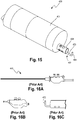
- FIG. 15 Another forearm 400 embodiment that can be used with the various robotic device embodiments described above is depicted in FIG. 15 .
- the forearm 400 has a cautery end effector 402 that also provides suction and irrigation.
- the end effector 402 is rotatable around its longitudinal axis.
- suction is used to remove fluid and small pieces of tissue from the patient during a procedure.
- irrigation relates to the flooding of a fluid, generally saline, in order to clean a surface and to clear away blood in order to identify and locate bleeding.
- the forearm 400 implementation improves upon the known SurgiWandTM device 410 depicted in FIGS. 16A-16C , which also combines a monopolar hook cautery 412 with suction and irrigation capabilities.
- the specific forearm 400 embodiment as shown in FIG. 15 provides a cautery end effector 402 having suction and irrigation on a forearm 400 of a robotic device that can be positioned entirely within a cavity of a patient or positioned in an incision (including a single incision) such that the device can perform a procedure within the patient's cavity.
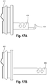
- the forearm 400 has a forearm body 401, and the cautery end effector 402 has a cautery hook 404, a distal cautery shaft 406, and an extendable sleeve 408.
- the extendable sleeve 408 can move between a retracted position as shown in FIG. 17A and an extended position as shown in FIG. 17B . In the retracted position, the cautery hook 404 is exposed and can be used to perform a cauterization, while in the extended position, the sleeve 408 encloses and protects the hook 404 such that the hook 404 cannot make inadvertent contact with any tissues.
- the sleeve 408 can be positioned in its extended position when the cautery hook is not being used - especially during positioning of the robotic device and/or the forearm 400. Once the forearm 400 (and thus the end effector 402) is positioned as desired, the sleeve 408 can be retracted to its retracted position so that the cautery hook 404 is exposed and can be used to cauterize a target tissue.
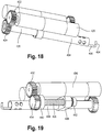
- FIGS. 18 and 19 The actuation components used to operate the end effector 402 are depicted in FIGS. 18 and 19 , according to certain implementations. More specifically, FIG. 18 best depicts one embodiment of the components that operate to cause the end effector 402 to rotate around its longitudinal axis.
- an actuation component 420 that in this example is a motor 420.
- the motor 420 is rotationally coupled to drive gear 422, which is rotationally coupled to driven gear 424.
- the driven gear 424 is rotationally coupled to the proximal cautery shaft 426 (which is coupled to the distal cautery shaft 406).
- the proximal cautery shaft 426 can be supported by one or more bearings (not shown).
- the shaft 426 can also be electrically coupled to a flexible electrical contact (not shown) that is slideably disposed along the length of the shaft 426 such that it is positioned around and in contact with the circumference of the shaft 426.
- the electrical contact is electrically coupled to an external cautery generator that is located at a location that is external to the patient.
- the proximal and distal cautery shafts constitute a single, unitary cautery shaft.
- FIG. 19 shows one implementation of the components that operate to cause the sleeve 408 to move between its retracted and extended positions.
- the forearm body 401 also has an actuation component 430 that in this example is a motor 430.
- the motor 430 is rotationally coupled to drive gear 432, which is rotationally coupled to driven gear 434.
- the driven gear 434 is rotationally coupled to a threaded leadscrew 436, and both are supported by bearings 440, 442.
- the leadscrew 436 is coupled to a nut 438.
- the nut 438 has an internal, threaded lumen through which the leadscrew 436 is positioned such that the external threads of the leadscrew 436 are threadably coupled to the internal threads of the nut 438.
- the nut 438 is constrained such that it cannot rotate. More specifically, in this particular embodiment, the nut 438 is shaped and positioned within the body 401 of the forearm 400 such that the nut 438 does not rotate when the leadscrew 436 is rotated. Further, the nut 438 is coupled to the retractable sleeve 408 such that movement of the nut 438 causes movement of the sleeve 408.
- the drive gear 432 rotates, thereby rotating the driven gear 434.
- Rotation of the driven gear 434 causes rotation of the leadscrew 436, which causes the nut 438 to translate axially, which causes the sleeve 408 to extend or retract. As best shown in FIGS. 18 and 19 , the sleeve 408 slides along and thus is supported by the proximal cautery shaft 426.
- FIG. 20 depicts a proximal portion of the forearm 400, showing the proximal end of the proximal cautery shaft 426.
- the proximal end of the shaft 426 has a concentric port 450 that connects an external suction/irrigation line to the cautery shaft 426. More specifically, the port 450 connects to the cautery shaft 426 and further connects to external port 452.
- the concentric port 450 may or may not have a sealing feature between the port 450 itself and the cautery shaft 426. Both the suction and irrigation aspects share a single lumen that extends to the surgical site in the cautery shaft 426.
- Dead space is the volume that is not directly controlled by the valve.
- the entire volume of the cautery shaft is dead space since - for example - irrigation does not stop when the valve is released but rather after the irrigation fluid has been drained from the shaft. Minimizing that dead space can result in better reaction times for the system.
- One method for limiting that dead space would be to run two lumens to the forearm and then have them combine with the single cautery shaft.
- the valves are located at the back of the forearm 400. In the preferred embodiment, the valves are located extracorporeal to the patient and the lines rely on the surface tension and produced vacuum of the irrigation fluid to prevent unintended drainage of the fluid.
- alternative embodiments of the forearm with the cautery end effector can use pneumatics, hydraulics, shape memory metals, or alternative drive methods to further improve the behavior of the suction/irrigation sleeve.
- brushless motors can be used.
- certain embodiments have a retractable sleeve that has additional holes along the outer edge and extending upwards along the axis of the sleeve. These holes can help to prevent damaging forces during occlusion of the suction tip.
- the suction/irrigation configuration with the single lumen extending along the length of the forearm could also be used in other types of forearms and/or end effectors, such as graspers or scissors.
Landscapes
- Engineering & Computer Science (AREA)
- Health & Medical Sciences (AREA)
- Surgery (AREA)
- Life Sciences & Earth Sciences (AREA)
- Robotics (AREA)
- Mechanical Engineering (AREA)
- Veterinary Medicine (AREA)
- General Health & Medical Sciences (AREA)
- Biomedical Technology (AREA)
- Heart & Thoracic Surgery (AREA)
- Medical Informatics (AREA)
- Molecular Biology (AREA)
- Animal Behavior & Ethology (AREA)
- Nuclear Medicine, Radiotherapy & Molecular Imaging (AREA)
- Public Health (AREA)
- Physics & Mathematics (AREA)
- Otolaryngology (AREA)
- Plasma & Fusion (AREA)
- Manipulator (AREA)
- Surgical Instruments (AREA)
Claims (15)
- Dispositif robotique (10) comprenant :(a) un corps allongé de dispositif comprenant :(i) une première transmission à engrenage inférieur comprenant :(A) un premier moteur (58) positionné dans le corps allongé de dispositif ; et(B) un premier arbre d'entraînement (30) couplé de manière opérationnelle au premier moteur (58) et à un premier engrenage conique inférieur (72), dans lequel le premier arbre d'entraînement (30) est disposé à l'intérieur d'un premier engrenage conique supérieur (70), et peut tourner indépendamment de celui-ci, et est concentrique avec le premier engrenage conique inférieur (72) et le premier engrenage conique supérieur (70) ; et(ii) une première transmission à engrenage supérieur comprenant un deuxième moteur (84) positionné dans le corps allongé de dispositif, le deuxième moteur (84) étant couplé de manière opérationnelle au premier engrenage conique supérieur (70) ;(b) une première articulation formant épaule (14D) comprenant un premier arbre de sortie (80) couplé de manière opérationnelle à un premier engrenage conique de sortie (74), dans lequel le premier engrenage conique de sortie (74) est couplé en rotation aux premiers engrenages coniques supérieur et inférieur (70, 72) ; et(c) un premier bras (14) couplé de manière opérationnelle à la première articulation formant épaule (14D).
- Dispositif robotique (10) selon la revendication 1, dans lequel le premier bras (14) est un premier bras supérieur (14A), dans lequel le dispositif (10) comprend en outre un premier avant-bras (14B) couplé de manière opérationnelle au premier bras supérieur (14A).
- Dispositif robotique (10) selon la revendication 2, comprenant en outre un premier effecteur terminal (224) couplé de manière opérationnelle au premier avant-bras (14B) .
- Dispositif robotique (10) selon l'une quelconque des revendications précédentes, dans lequel la partie distale du premier arbre d'entraînement (30) est disposée à travers le premier arbre de sortie (80).
- Dispositif robotique (10) selon l'une quelconque des revendications précédentes, dans lequel le premier moteur (58) provoque une rotation du premier engrenage conique inférieur (72) et le deuxième moteur (84) provoque une rotation du premier engrenage conique supérieur (70).
- Dispositif robotique (10) selon l'une quelconque des revendications précédentes, dans lequel le premier arbre de sortie (80) a un premier bras de sortie (160) qui s'étend au loin du premier arbre d'entraînement (30), dans lequel un roulement (120) est inséré dans le premier engrenage conique de sortie (74), le roulement reposant sur une épaule (162) du premier bras de sortie (160).
- Dispositif robotique (10) selon l'une quelconque des revendications précédentes, comprenant en outre :(a) un premier engrenage d'entraînement (56) couplé au premier moteur (58) de telle sorte que l'actionnement du premier moteur (58) provoque une rotation du premier engrenage d'entraînement (56) ; et(b) un premier engrenage entraîné (54) couplé en rotation au premier engrenage d'entraînement (56), dans lequel le premier arbre d'entraînement (30) est disposé en rotation à travers le premier engrenage entraîné (54).
- Dispositif robotique (10) selon l'une quelconque des revendications précédentes, dans lequel ni un moteur ni un arbre d'entraînement ne passe le long de l'extérieur des premiers engrenages coniques supérieur et inférieur (70, 72) .
- Dispositif robotique (10) selon la revendication 1, comprenant en outre :(a) une seconde transmission à engrenage inférieur comprenant :(i) un troisième moteur ;(ii) un second arbre d'entraînement (32) couplé de manière opérationnelle au troisième moteur et à un second engrenage conique inférieur, dans lequel le second arbre d'entraînement (32) est disposé à l'intérieur d'un second engrenage conique supérieur, et peut tourner indépendamment de celui-ci, et est concentrique avec le second engrenage inférieur conique et le second engrenage conique supérieur ;(b) une seconde transmission à engrenage supérieur comprenant un quatrième moteur couplé de manière opérationnelle au second engrenage conique supérieur ;(c) une seconde articulation formant épaule (16D) comprenant un second arbre de sortie (36) couplé de manière opérationnelle à un second engrenage conique de sortie, le second engrenage conique de sortie étant couplé en rotation aux seconds engrenages coniques supérieur et inférieur ; et(d) un second bras (16) couplé de manière opérationnelle à la seconde articulation formant épaule (16D) .
- Dispositif robotique (10) selon la revendication 9, dans lequel le second bras est un second bras supérieur (16A), dans lequel le dispositif comprend en outre un second avant-bras (16B) couplé de manière opérationnelle au second bras supérieur (16A).
- Dispositif robotique (10) selon la revendication 10, comprenant en outre un second effecteur terminal couplé de manière opérationnelle au second avant-bras (16B).
- Dispositif robotique (10) selon l'une quelconque des revendications 9 à 11, dans lequel le second arbre d'entraînement (32) est disposé à travers le second arbre de sortie (36).
- Dispositif robotique (10) selon l'une quelconque des revendications 9 à 12, dans lequel le troisième moteur provoque une rotation du second engrenage conique inférieur et le quatrième moteur provoque une rotation du second engrenage conique supérieur.
- Dispositif robotique (10) selon l'une quelconque des revendications 9 à 13, dans lequel le second arbre de sortie (36) a un second bras de sortie qui s'étend au loin du second arbre d'entraînement (32), dans lequel un roulement est inséré dans le second engrenage conique de sortie, le roulement reposant sur une épaule du second bras de sortie.
- Dispositif robotique (10) selon l'une quelconque des revendications 9 à 14, comprenant en outre :(a) un second engrenage d'entraînement couplé au quatrième moteur de telle sorte que l'actionnement du quatrième moteur provoque une rotation du second engrenage d'entraînement ; et(b) un second engrenage entraîné couplé en rotation au second engrenage d'entraînement, dans lequel le second arbre d'entraînement (32) est disposé en rotation à travers le second engrenage entraîné.
Priority Applications (2)
| Application Number | Priority Date | Filing Date | Title |
|---|---|---|---|
| EP23205103.7A EP4286104A3 (fr) | 2014-11-11 | 2015-11-11 | Dispositif robotique à conception d'articulation compacte et systèmes et procédés associés |
| EP20158605.4A EP3689257B1 (fr) | 2014-11-11 | 2015-11-11 | Dispositif robotique avec conception de joint compacte et systèmes et procédés associés |
Applications Claiming Priority (2)
| Application Number | Priority Date | Filing Date | Title |
|---|---|---|---|
| US201462078192P | 2014-11-11 | 2014-11-11 | |
| PCT/US2015/060196 WO2016077478A1 (fr) | 2014-11-11 | 2015-11-11 | Dispositif robotisé à modèle d'articulation compacte, ainsi que systèmes et procédés associés |
Related Child Applications (3)
| Application Number | Title | Priority Date | Filing Date |
|---|---|---|---|
| EP23205103.7A Division EP4286104A3 (fr) | 2014-11-11 | 2015-11-11 | Dispositif robotique à conception d'articulation compacte et systèmes et procédés associés |
| EP20158605.4A Division EP3689257B1 (fr) | 2014-11-11 | 2015-11-11 | Dispositif robotique avec conception de joint compacte et systèmes et procédés associés |
| EP20158605.4A Division-Into EP3689257B1 (fr) | 2014-11-11 | 2015-11-11 | Dispositif robotique avec conception de joint compacte et systèmes et procédés associés |
Publications (3)
| Publication Number | Publication Date |
|---|---|
| EP3217890A1 EP3217890A1 (fr) | 2017-09-20 |
| EP3217890A4 EP3217890A4 (fr) | 2018-08-22 |
| EP3217890B1 true EP3217890B1 (fr) | 2020-04-08 |
Family
ID=55954998
Family Applications (3)
| Application Number | Title | Priority Date | Filing Date |
|---|---|---|---|
| EP20158605.4A Active EP3689257B1 (fr) | 2014-11-11 | 2015-11-11 | Dispositif robotique avec conception de joint compacte et systèmes et procédés associés |
| EP15859761.7A Active EP3217890B1 (fr) | 2014-11-11 | 2015-11-11 | Dispositif robotisé à modèle d'articulation compacte |
| EP23205103.7A Pending EP4286104A3 (fr) | 2014-11-11 | 2015-11-11 | Dispositif robotique à conception d'articulation compacte et systèmes et procédés associés |
Family Applications Before (1)
| Application Number | Title | Priority Date | Filing Date |
|---|---|---|---|
| EP20158605.4A Active EP3689257B1 (fr) | 2014-11-11 | 2015-11-11 | Dispositif robotique avec conception de joint compacte et systèmes et procédés associés |
Family Applications After (1)
| Application Number | Title | Priority Date | Filing Date |
|---|---|---|---|
| EP23205103.7A Pending EP4286104A3 (fr) | 2014-11-11 | 2015-11-11 | Dispositif robotique à conception d'articulation compacte et systèmes et procédés associés |
Country Status (5)
| Country | Link |
|---|---|
| US (3) | US10376322B2 (fr) |
| EP (3) | EP3689257B1 (fr) |
| JP (2) | JP6608928B2 (fr) |
| CA (1) | CA2967593C (fr) |
| WO (1) | WO2016077478A1 (fr) |
Cited By (1)
| Publication number | Priority date | Publication date | Assignee | Title |
|---|---|---|---|---|
| EP3735341B1 (fr) * | 2018-01-05 | 2024-10-02 | Board of Regents of the University of Nebraska | Dispositif robotique ayant un seul bras d'une conception d'articulation compacte et systèmes |
Families Citing this family (37)
| Publication number | Priority date | Publication date | Assignee | Title |
|---|---|---|---|---|
| WO2013048595A1 (fr) | 2011-06-10 | 2013-04-04 | Board Of Regents Of The University Of Nebraska | Procédés, systèmes et dispositifs relatifs à des effecteurs terminaux chirurgicaux |
| EP3588217A1 (fr) | 2011-07-11 | 2020-01-01 | Board of Regents of the University of Nebraska | Dispositifs chirurgicaux robotisés, systèmes et procédés associés |
| EP3730031A1 (fr) | 2011-10-03 | 2020-10-28 | Board of Regents of the University of Nebraska | Dispositifs chirurgicaux robotisés et systèmes |
| EP2806941B1 (fr) | 2012-01-10 | 2021-10-27 | Board of Regents of the University of Nebraska | Systèmes et dispositifs pour accès chirurgical et insertion chirurgicale |
| WO2014011238A2 (fr) | 2012-05-01 | 2014-01-16 | Board Of Regents Of The University Of Nebraska | Dispositif robotique à site unique et systèmes et procédés associés |
| EP4234185A3 (fr) | 2012-06-22 | 2023-09-20 | Board of Regents of the University of Nebraska | Dispositifs chirurgicaux robotiques de commande locale |
| CA2880622C (fr) | 2012-08-08 | 2021-01-12 | Board Of Regents Of The University Of Nebraska | Systemes et dispositifs chirurgicaux robotiques, et procedes associes |
| US12295680B2 (en) | 2012-08-08 | 2025-05-13 | Board Of Regents Of The University Of Nebraska | Robotic surgical devices, systems and related methods |
| WO2014152418A1 (fr) | 2013-03-14 | 2014-09-25 | Board Of Regents Of The University Of Nebraska | Procédés, systèmes et dispositifs associés à des systèmes chirurgicaux de commande de force |
| WO2014144220A1 (fr) * | 2013-03-15 | 2014-09-18 | Board Of Regents Of The University Of Nebraska | Dispositifs chirurgicaux robotiques, systèmes et procédés apparentés |
| CA2918531A1 (fr) | 2013-07-17 | 2015-01-22 | Board Of Regents Of The University Of Nebraska | Dispositifs chirurgicaux robotiques, systemes et procedes apparentes |
| US9895200B2 (en) | 2014-04-22 | 2018-02-20 | Bio-Medical Engineering (HK) Limited | Robotic devices and systems for performing single incision procedures and natural orifice translumenal endoscopic surgical procedures, and methods of configuring robotic devices and systems |
| US11090123B2 (en) | 2014-04-22 | 2021-08-17 | Bio-Medical Engineering (HK) Limited | Robotic devices and systems for performing single incision procedures and natural orifice translumenal endoscopic surgical procedures, and methods of configuring robotic devices and systems |
| EP3134006B1 (fr) | 2014-04-22 | 2020-02-12 | Bio-Medical Engineering (HK) Limited | Dispositifs et systèmes robotiques chirurgicaux d'accès unique |
| US10500008B2 (en) | 2014-04-22 | 2019-12-10 | Bio-Medical Engineering (HK) Limited | Surgical arm system with internally driven gear assemblies |
| WO2016040946A1 (fr) | 2014-09-12 | 2016-03-17 | Board Of Regents Of University Of Nebraska | Effecteurs d'extrémité à libération rapide et systèmes et procédés associés |
| EP3689257B1 (fr) | 2014-11-11 | 2024-01-03 | Board of Regents of the University of Nebraska | Dispositif robotique avec conception de joint compacte et systèmes et procédés associés |
| GB2541369B (en) * | 2015-07-22 | 2021-03-31 | Cmr Surgical Ltd | Drive mechanisms for robot arms |
| GB2540756B (en) * | 2015-07-22 | 2021-03-31 | Cmr Surgical Ltd | Gear packaging for robot arms |
| WO2017013451A1 (fr) | 2015-07-22 | 2017-01-26 | Cambridge Medical Robotics Ltd | Emballage d'engrenage pour bras de robot |
| CA2994823A1 (fr) | 2015-08-03 | 2017-02-09 | Board Of Regents Of The University Of Nebraska | Systemes de dispositifs chirurgicaux robotises et procedes apparentes |
| EP3457951B1 (fr) | 2016-05-18 | 2024-03-06 | Virtual Incision Corporation | Dispositifs chirurgicaux robotiques et systèmes |
| WO2017205576A1 (fr) * | 2016-05-26 | 2017-11-30 | Covidien Lp | Unité de commande d'instruments |
| JP2019524371A (ja) | 2016-08-25 | 2019-09-05 | ボード オブ リージェンツ オブ ザ ユニバーシティ オブ ネブラスカ | クイックリリースツールカプラ並びに関連するシステム及び方法 |
| EP4523648B1 (fr) * | 2016-08-30 | 2026-02-25 | Board of Regents of the University of Nebraska | Dispositif robotique à conception d'articulation compacte et à degré de liberté supplémentaire |
| CA3035311C (fr) | 2016-08-31 | 2023-08-29 | Beijing Surgerii Technology Co., Ltd. | Procede de detection de defaillance d'etat de fonctionnement d'un robot chirurgical |
| CN115553922A (zh) | 2016-11-29 | 2023-01-03 | 虚拟切割有限公司 | 具有用户存在检测的用户控制器及相关系统和方法 |
| CA3076625A1 (fr) | 2017-09-27 | 2019-04-04 | Virtual Incision Corporation | Dispositifs chirurgicaux robotises avec technologie de camera de suivi et systemes et procedes apparentes |
| US11376940B2 (en) * | 2018-12-13 | 2022-07-05 | University Of Florida Research Foundation, Incorporated | Highly mobile robot for remote inspection |
| JP7546926B2 (ja) | 2019-01-07 | 2024-09-09 | バーチャル インシジョン コーポレイション | ロボット支援手術システムと関連する装置と方法 |
| WO2020258404A1 (fr) * | 2019-06-28 | 2020-12-30 | Bio-Medical Engineering (HK) Limited | Système de bras chirurgical à train d'engrenages à entraînement interne |
| CN114051403B (zh) * | 2019-06-28 | 2026-03-17 | 奥瑞斯健康公司 | 用于机器人系统的患者导引器 |
| WO2020258405A1 (fr) * | 2019-06-28 | 2020-12-30 | Bio-Medical Engineering (HK) Limited | Système de bras chirurgical doté de trains d'engrenages à entraînement interne |
| CN112472166B (zh) * | 2020-11-23 | 2022-05-20 | 中国人民解放军陆军军医大学第二附属医院 | 单孔可调无创牵拉器 |
| US20220204100A1 (en) * | 2020-12-31 | 2022-06-30 | Sarcos Corp. | Coupleable, Unmanned Ground Vehicles with Coordinated Control |
| JP7587439B2 (ja) * | 2021-02-24 | 2024-11-20 | 株式会社ソニー・インタラクティブエンタテインメント | 回転装置 |
| CN115005993B (zh) * | 2022-05-31 | 2023-09-22 | 四川省肿瘤医院 | 一种弯曲机构及应用该机构的手术机械臂 |
Family Cites Families (554)
| Publication number | Priority date | Publication date | Assignee | Title |
|---|---|---|---|---|
| US2858947A (en) | 1953-11-16 | 1958-11-04 | Garrett Corp | Remote control manipulating apparatus |
| FR2183584B1 (fr) | 1972-05-10 | 1974-09-27 | Commissariat Energie Atomique | |
| US3870264A (en) | 1973-03-26 | 1975-03-11 | William I Robinson | Stand |
| US3971266A (en) | 1973-07-17 | 1976-07-27 | Nippondenso Co., Ltd. | Power transmission device |
| DE2339827B2 (de) | 1973-08-06 | 1977-02-24 | A6 In 3-02 | Zahnaerztliches geraet |
| JPS5115425A (ja) | 1974-07-29 | 1976-02-06 | Yashica Co Ltd | Denjireriizushikisuchiirukameraniokeru mootadoraibusochi |
| US3922930A (en) | 1974-12-23 | 1975-12-02 | Nasa | Remotely operable articulated manipulator |
| US4258716A (en) | 1978-02-06 | 1981-03-31 | The University Of Melbourne | Microsurgical instruments |
| JPS5519124A (en) | 1978-07-27 | 1980-02-09 | Olympus Optical Co | Camera system for medical treatment |
| US4246661A (en) | 1979-03-15 | 1981-01-27 | The Boeing Company | Digitally-controlled artificial hand |
| US4353677A (en) | 1980-03-05 | 1982-10-12 | Thermwood Corporation | Wrist construction for industrial robots |
| JPH0659635B2 (ja) | 1981-10-07 | 1994-08-10 | 株式会社日立製作所 | ロボツト手首 |
| JPS58132490A (ja) | 1982-01-29 | 1983-08-06 | 株式会社日立製作所 | 角度伝達機構 |
| US4645409A (en) | 1982-02-05 | 1987-02-24 | American Cimflex Corporation | Outer arm assembly for industrial robot |
| US4636138A (en) | 1982-02-05 | 1987-01-13 | American Robot Corporation | Industrial robot |
| JPS5959371A (ja) | 1982-09-30 | 1984-04-05 | フアナツク株式会社 | 工業用ロボツト |
| US5307447A (en) | 1982-10-29 | 1994-04-26 | Kabushiki Kaisha Toshiba | Control system of multi-joint arm robot apparatus |
| GB2130889B (en) | 1982-11-26 | 1986-06-18 | Wolf Gmbh Richard | Rectoscope |
| JPS601456A (ja) | 1983-06-17 | 1985-01-07 | Agency Of Ind Science & Technol | 一点中心型3自由度駆動機構 |
| JPS6076986A (ja) | 1983-09-30 | 1985-05-01 | 株式会社東芝 | ロボツト |
| WO1985003024A1 (fr) | 1984-01-13 | 1985-07-18 | Mitsubishi Denki Kabushiki Kaisha | Dispositif de poignet pour robot industriel |
| DE3536747A1 (de) | 1984-10-15 | 1986-04-24 | Tokico Ltd., Kawasaki, Kanagawa | Gelenkmechanismus |
| DE3441332A1 (de) | 1984-11-12 | 1986-05-22 | Forschungsinstitut für Steuerungstechnik der Werkzeugmaschinen und Fertigungseinrichtungen in der Institutsgemeinschaft Stuttgart e.V., 7000 Stuttgart | Gelenkantrieb, insbesondere fuer industrieroboter |
| DE3525806A1 (de) | 1985-07-19 | 1987-01-29 | Kuka Schweissanlagen & Roboter | Getriebekopf fuer manipulatoren |
| JPS6268293A (ja) * | 1985-09-20 | 1987-03-28 | 株式会社明電舎 | マニピユレ−タ肩機構 |
| DE3545068A1 (de) | 1985-12-19 | 1987-06-25 | Kuka Schweissanlagen & Roboter | Getriebekopf fuer manipulatoren |
| DE3612498A1 (de) | 1986-04-14 | 1987-10-29 | Norske Stats Oljeselskap | Selbstfahrendes fahrzeug fuer rohrleitungen |
| US4787270A (en) | 1987-02-11 | 1988-11-29 | Cincinnati Milacron Inc. | Robotic manipulator |
| US4762455A (en) | 1987-06-01 | 1988-08-09 | Remote Technology Corporation | Remote manipulator |
| IT1211195B (it) | 1987-07-10 | 1989-10-12 | Bruno Bisiach | Robot industriale a molteplici articolazioni a piu gradi di liberta di movimento |
| US5036724A (en) | 1987-11-30 | 1991-08-06 | Rosheim Mark E | Robot wrist |
| JP2591968B2 (ja) | 1987-12-28 | 1997-03-19 | 株式会社日立製作所 | 産業用ロボットの手首 |
| US5187796A (en) | 1988-03-29 | 1993-02-16 | Computer Motion, Inc. | Three-dimensional vector co-processor having I, J, and K register files and I, J, and K execution units |
| US5019968A (en) | 1988-03-29 | 1991-05-28 | Yulan Wang | Three-dimensional vector processor |
| US5108140A (en) | 1988-04-18 | 1992-04-28 | Odetics, Inc. | Reconfigurable end effector |
| JPH0224075A (ja) | 1988-07-13 | 1990-01-26 | Mitsubishi Electric Corp | 産業用ロボット |
| US4896015A (en) | 1988-07-29 | 1990-01-23 | Refractive Laser Research & Development Program, Ltd. | Laser delivery system |
| US4897014A (en) | 1988-09-06 | 1990-01-30 | Harbor Branch Oceanographic Institution, Inc. | Device for interchange of tools |
| US5271384A (en) | 1989-09-01 | 1993-12-21 | Mcewen James A | Powered surgical retractor |
| US5201325A (en) | 1989-09-01 | 1993-04-13 | Andronic Devices Ltd. | Advanced surgical retractor |
| JPH03202287A (ja) * | 1989-12-28 | 1991-09-04 | Toyoda Mach Works Ltd | 工業用ロボット |
| US5562448A (en) | 1990-04-10 | 1996-10-08 | Mushabac; David R. | Method for facilitating dental diagnosis and treatment |
| JP2914388B2 (ja) | 1990-04-17 | 1999-06-28 | 株式会社ユアサコーポレーション | 高分子固体電解質 |
| IT1241622B (it) | 1990-10-04 | 1994-01-25 | Comau Spa | Polso di robot |
| IT1241621B (it) | 1990-10-04 | 1994-01-25 | Comau Spa | Robot articolato |
| JPH04144533A (ja) | 1990-10-05 | 1992-05-19 | Olympus Optical Co Ltd | 内視鏡 |
| US5176649A (en) | 1991-01-28 | 1993-01-05 | Akio Wakabayashi | Insertion device for use with curved, rigid endoscopic instruments and the like |
| US5217003A (en) | 1991-03-18 | 1993-06-08 | Wilk Peter J | Automated surgical system and apparatus |
| US5172639A (en) | 1991-03-26 | 1992-12-22 | Gas Research Institute | Cornering pipe traveler |
| DK0637223T3 (da) | 1991-05-29 | 1999-04-26 | Origin Medsystems Inc | Tilbageholdelsesanordning til endoskopisk kirurgi |
| US5370134A (en) | 1991-05-29 | 1994-12-06 | Orgin Medsystems, Inc. | Method and apparatus for body structure manipulation and dissection |
| US5632761A (en) | 1991-05-29 | 1997-05-27 | Origin Medsystems, Inc. | Inflatable devices for separating layers of tissue, and methods of using |
| US5417210A (en) | 1992-05-27 | 1995-05-23 | International Business Machines Corporation | System and method for augmentation of endoscopic surgery |
| US5284096A (en) | 1991-08-06 | 1994-02-08 | Osaka Gas Company, Limited | Vehicle for use in pipes |
| US5674030A (en) | 1991-08-27 | 1997-10-07 | Sika Equipment Ag. | Device and method for repairing building branch lines in inacessible sewer mains |
| JP2526537B2 (ja) | 1991-08-30 | 1996-08-21 | 日本電装株式会社 | 配管内エネルギ―供給システム |
| US5305653A (en) | 1991-09-30 | 1994-04-26 | Tokico Ltd. | Robot wrist mechanism |
| JPH05115425A (ja) | 1991-10-25 | 1993-05-14 | Olympus Optical Co Ltd | 内視鏡 |
| ATE215430T1 (de) | 1992-01-21 | 2002-04-15 | Stanford Res Inst Int | Endoskopisches chirurgisches instrument |
| US6963792B1 (en) | 1992-01-21 | 2005-11-08 | Sri International | Surgical method |
| US6731988B1 (en) | 1992-01-21 | 2004-05-04 | Sri International | System and method for remote endoscopic surgery |
| US5631973A (en) | 1994-05-05 | 1997-05-20 | Sri International | Method for telemanipulation with telepresence |
| US5624380A (en) | 1992-03-12 | 1997-04-29 | Olympus Optical Co., Ltd. | Multi-degree of freedom manipulator |
| US5263382A (en) | 1992-04-13 | 1993-11-23 | Hughes Aircraft Company | Six Degrees of freedom motion device |
| US5372147A (en) | 1992-06-16 | 1994-12-13 | Origin Medsystems, Inc. | Peritoneal distension robotic arm |
| US5297443A (en) | 1992-07-07 | 1994-03-29 | Wentz John D | Flexible positioning appendage |
| US5515478A (en) | 1992-08-10 | 1996-05-07 | Computer Motion, Inc. | Automated endoscope system for optimal positioning |
| US5657429A (en) | 1992-08-10 | 1997-08-12 | Computer Motion, Inc. | Automated endoscope system optimal positioning |
| US5524180A (en) | 1992-08-10 | 1996-06-04 | Computer Motion, Inc. | Automated endoscope system for optimal positioning |
| US5762458A (en) | 1996-02-20 | 1998-06-09 | Computer Motion, Inc. | Method and apparatus for performing minimally invasive cardiac procedures |
| US7074179B2 (en) | 1992-08-10 | 2006-07-11 | Intuitive Surgical Inc | Method and apparatus for performing minimally invasive cardiac procedures |
| US5754741A (en) | 1992-08-10 | 1998-05-19 | Computer Motion, Inc. | Automated endoscope for optimal positioning |
| US5588442A (en) | 1992-08-12 | 1996-12-31 | Scimed Life Systems, Inc. | Shaft movement control apparatus and method |
| US5458131A (en) | 1992-08-25 | 1995-10-17 | Wilk; Peter J. | Method for use in intra-abdominal surgery |
| US5297536A (en) | 1992-08-25 | 1994-03-29 | Wilk Peter J | Method for use in intra-abdominal surgery |
| US5397323A (en) | 1992-10-30 | 1995-03-14 | International Business Machines Corporation | Remote center-of-motion robot for surgery |
| US5769640A (en) | 1992-12-02 | 1998-06-23 | Cybernet Systems Corporation | Method and system for simulating medical procedures including virtual reality and control method and system for use therein |
| US5353807A (en) | 1992-12-07 | 1994-10-11 | Demarco Thomas J | Magnetically guidable intubation device |
| CA2112271A1 (fr) | 1992-12-28 | 1994-06-29 | Kiichi Suyama | Robot d'intervention dans des canalisations et methode de localisation connexe |
| EP0683684B1 (fr) | 1993-01-07 | 2001-08-08 | Medical Innovations Corporation | Systeme catheter pour gastrostomie |
| US6346074B1 (en) | 1993-02-22 | 2002-02-12 | Heartport, Inc. | Devices for less invasive intracardiac interventions |
| US6832996B2 (en) | 1995-06-07 | 2004-12-21 | Arthrocare Corporation | Electrosurgical systems and methods for treating tissue |
| US5363935A (en) | 1993-05-14 | 1994-11-15 | Carnegie Mellon University | Reconfigurable mobile vehicle with magnetic tracks |
| US5791231A (en) | 1993-05-17 | 1998-08-11 | Endorobotics Corporation | Surgical robotic system and hydraulic actuator therefor |
| JP3349197B2 (ja) | 1993-06-30 | 2002-11-20 | テルモ株式会社 | トロカール管 |
| US5441494A (en) | 1993-07-29 | 1995-08-15 | Ethicon, Inc. | Manipulable hand for laparoscopy |
| US5382885A (en) | 1993-08-09 | 1995-01-17 | The University Of British Columbia | Motion scaling tele-operating system with force feedback suitable for microsurgery |
| US5728599A (en) | 1993-10-28 | 1998-03-17 | Lsi Logic Corporation | Printable superconductive leadframes for semiconductor device assembly |
| US5876325A (en) | 1993-11-02 | 1999-03-02 | Olympus Optical Co., Ltd. | Surgical manipulation system |
| JP3476878B2 (ja) | 1993-11-15 | 2003-12-10 | オリンパス株式会社 | 手術用マニピュレータ |
| US5458598A (en) | 1993-12-02 | 1995-10-17 | Cabot Technology Corporation | Cutting and coagulating forceps |
| WO1995016396A1 (fr) | 1993-12-15 | 1995-06-22 | Computer Motion, Inc. | Systeme automatise d'endoscope permettant un positionnement optimal |
| US5436542A (en) | 1994-01-28 | 1995-07-25 | Surgix, Inc. | Telescopic camera mount with remotely controlled positioning |
| US5471515A (en) | 1994-01-28 | 1995-11-28 | California Institute Of Technology | Active pixel sensor with intra-pixel charge transfer |
| JPH07223180A (ja) | 1994-02-10 | 1995-08-22 | Tescon:Kk | 水平多関節ロボット |
| US5456673A (en) | 1994-03-23 | 1995-10-10 | Stryker Corporation | Locking cannula for endoscopic surgery |
| JP3226710B2 (ja) | 1994-05-10 | 2001-11-05 | 株式会社東芝 | 検査用画像処理装置及び方式 |
| US5620417A (en) | 1994-07-07 | 1997-04-15 | Cardiovascular Imaging Systems Incorporated | Rapid exchange delivery catheter |
| US5623582A (en) | 1994-07-14 | 1997-04-22 | Immersion Human Interface Corporation | Computer interface or control input device for laparoscopic surgical instrument and other elongated mechanical objects |
| US5603702A (en) | 1994-08-08 | 1997-02-18 | United States Surgical Corporation | Valve system for cannula assembly |
| US6646541B1 (en) | 1996-06-24 | 2003-11-11 | Computer Motion, Inc. | General purpose distributed operating room control system |
| US6463361B1 (en) | 1994-09-22 | 2002-10-08 | Computer Motion, Inc. | Speech interface for an automated endoscopic system |
| US7053752B2 (en) | 1996-08-06 | 2006-05-30 | Intuitive Surgical | General purpose distributed operating room control system |
| US5797538A (en) | 1994-10-05 | 1998-08-25 | United States Surgical Corporation | Articulating apparatus for applying surgical fasteners to body tissue |
| US5653705A (en) | 1994-10-07 | 1997-08-05 | General Surgical Innovations, Inc. | Laparoscopic access port for surgical instruments or the hand |
| US5672168A (en) | 1994-10-07 | 1997-09-30 | De La Torre; Roger A. | Laparoscopic access port for surgical instruments or the hand |
| US6071274A (en) | 1996-12-19 | 2000-06-06 | Ep Technologies, Inc. | Loop structures for supporting multiple electrode elements |
| US5645520A (en) | 1994-10-12 | 1997-07-08 | Computer Motion, Inc. | Shape memory alloy actuated rod for endoscopic instruments |
| US5814062A (en) | 1994-12-22 | 1998-09-29 | Target Therapeutics, Inc. | Implant delivery assembly with expandable coupling/decoupling mechanism |
| JP3610110B2 (ja) | 1995-02-23 | 2005-01-12 | オリンパス株式会社 | 医療用マニピュレータ |
| GB2301187B (en) | 1995-05-22 | 1999-04-21 | British Gas Plc | Method of and apparatus for locating an anomaly in a duct |
| US5657584A (en) | 1995-07-24 | 1997-08-19 | Rensselaer Polytechnic Institute | Concentric joint mechanism |
| US6714841B1 (en) | 1995-09-15 | 2004-03-30 | Computer Motion, Inc. | Head cursor control interface for an automated endoscope system for optimal positioning |
| US5825982A (en) | 1995-09-15 | 1998-10-20 | Wright; James | Head cursor control interface for an automated endoscope system for optimal positioning |
| US6283951B1 (en) | 1996-10-11 | 2001-09-04 | Transvascular, Inc. | Systems and methods for delivering drugs to selected locations within the body |
| US5624398A (en) | 1996-02-08 | 1997-04-29 | Symbiosis Corporation | Endoscopic robotic surgical tools and methods |
| US5971976A (en) | 1996-02-20 | 1999-10-26 | Computer Motion, Inc. | Motion minimization and compensation system for use in surgical procedures |
| US6436107B1 (en) | 1996-02-20 | 2002-08-20 | Computer Motion, Inc. | Method and apparatus for performing minimally invasive surgical procedures |
| US5855583A (en) | 1996-02-20 | 1999-01-05 | Computer Motion, Inc. | Method and apparatus for performing minimally invasive cardiac procedures |
| US6063095A (en) | 1996-02-20 | 2000-05-16 | Computer Motion, Inc. | Method and apparatus for performing minimally invasive surgical procedures |
| US6699177B1 (en) | 1996-02-20 | 2004-03-02 | Computer Motion, Inc. | Method and apparatus for performing minimally invasive surgical procedures |
| US5895417A (en) | 1996-03-06 | 1999-04-20 | Cardiac Pathways Corporation | Deflectable loop design for a linear lesion ablation apparatus |
| US6544276B1 (en) | 1996-05-20 | 2003-04-08 | Medtronic Ave. Inc. | Exchange method for emboli containment |
| US5807377A (en) | 1996-05-20 | 1998-09-15 | Intuitive Surgical, Inc. | Force-reflecting surgical instrument and positioning mechanism for performing minimally invasive surgery with enhanced dexterity and sensitivity |
| US5797900A (en) | 1996-05-20 | 1998-08-25 | Intuitive Surgical, Inc. | Wrist mechanism for surgical instrument for performing minimally invasive surgery with enhanced dexterity and sensitivity |
| US6652480B1 (en) | 1997-03-06 | 2003-11-25 | Medtronic Ave., Inc. | Methods for reducing distal embolization |
| US5792135A (en) | 1996-05-20 | 1998-08-11 | Intuitive Surgical, Inc. | Articulated surgical instrument for performing minimally invasive surgery with enhanced dexterity and sensitivity |
| JP3794594B2 (ja) | 1996-06-21 | 2006-07-05 | 本田技研工業株式会社 | 組立作業補助台 |
| US6496099B2 (en) | 1996-06-24 | 2002-12-17 | Computer Motion, Inc. | General purpose distributed operating room control system |
| US6911916B1 (en) | 1996-06-24 | 2005-06-28 | The Cleveland Clinic Foundation | Method and apparatus for accessing medical data over a network |
| US6642836B1 (en) | 1996-08-06 | 2003-11-04 | Computer Motion, Inc. | General purpose distributed operating room control system |
| US6106521A (en) | 1996-08-16 | 2000-08-22 | United States Surgical Corporation | Apparatus for thermal treatment of tissue |
| US6364888B1 (en) | 1996-09-09 | 2002-04-02 | Intuitive Surgical, Inc. | Alignment of master and slave in a minimally invasive surgical apparatus |
| ES2235252T3 (es) | 1996-09-13 | 2005-07-01 | Schering Corporation | Inhibidores triciclicos de la farnesil proteina transferasa. |
| US6520951B1 (en) | 1996-09-13 | 2003-02-18 | Scimed Life Systems, Inc. | Rapid exchange catheter with detachable hood |
| IT1285533B1 (it) | 1996-10-22 | 1998-06-08 | Scuola Superiore Di Studi Universitari E Di Perfezionamento Sant Anna | Robot endoscopico |
| US6058323A (en) | 1996-11-05 | 2000-05-02 | Lemelson; Jerome | System and method for treating select tissue in a living being |
| US6286514B1 (en) | 1996-11-05 | 2001-09-11 | Jerome Lemelson | System and method for treating select tissue in a living being |
| US5845646A (en) | 1996-11-05 | 1998-12-08 | Lemelson; Jerome | System and method for treating select tissue in a living being |
| US6293282B1 (en) | 1996-11-05 | 2001-09-25 | Jerome Lemelson | System and method for treating select tissue in living being |
| US6132441A (en) | 1996-11-22 | 2000-10-17 | Computer Motion, Inc. | Rigidly-linked articulating wrist with decoupled motion transmission |
| US5993467A (en) | 1996-11-27 | 1999-11-30 | Yoon; Inbae | Suturing instrument with rotatably mounted spreadable needle holder |
| US6132368A (en) | 1996-12-12 | 2000-10-17 | Intuitive Surgical, Inc. | Multi-component telepresence system and method |
| US6331181B1 (en) | 1998-12-08 | 2001-12-18 | Intuitive Surgical, Inc. | Surgical robotic tools, data architecture, and use |
| US5910129A (en) | 1996-12-19 | 1999-06-08 | Ep Technologies, Inc. | Catheter distal assembly with pull wires |
| US6332880B1 (en) | 1996-12-19 | 2001-12-25 | Ep Technologies, Inc. | Loop structures for supporting multiple electrode elements |
| US6086529A (en) | 1997-05-13 | 2000-07-11 | Wisconsin Medical, Inc. | Bronchoscopic manifold with compressible diaphragmatic valve for simultaneous airway instrumentation |
| US6066090A (en) | 1997-06-19 | 2000-05-23 | Yoon; Inbae | Branched endoscope system |
| WO1999009140A1 (fr) | 1997-08-20 | 1999-02-25 | The Regents Of The University Of California | Sequences nucleotidiques codant pour le recepteur de la capsicine, polypeptides lies au recepteur de la capsicine et leur utilisation |
| US6714839B2 (en) | 1998-12-08 | 2004-03-30 | Intuitive Surgical, Inc. | Master having redundant degrees of freedom |
| US6139563A (en) | 1997-09-25 | 2000-10-31 | Allegiance Corporation | Surgical device with malleable shaft |
| JP3342021B2 (ja) | 1997-10-17 | 2002-11-05 | サーコン コーポレーション | 組織を貫通する医療機器システム |
| US6240312B1 (en) | 1997-10-23 | 2001-05-29 | Robert R. Alfano | Remote-controllable, micro-scale device for use in in vivo medical diagnosis and/or treatment |
| FR2771280B1 (fr) | 1997-11-26 | 2001-01-26 | Albert P Alby | Dispositif de liaison vertebrale resilient |
| US7090683B2 (en) | 1998-02-24 | 2006-08-15 | Hansen Medical, Inc. | Flexible instrument |
| US7169141B2 (en) | 1998-02-24 | 2007-01-30 | Hansen Medical, Inc. | Surgical instrument |
| US6692485B1 (en) | 1998-02-24 | 2004-02-17 | Endovia Medical, Inc. | Articulated apparatus for telemanipulator system |
| US6810281B2 (en) | 2000-12-21 | 2004-10-26 | Endovia Medical, Inc. | Medical mapping system |
| US20020095175A1 (en) | 1998-02-24 | 2002-07-18 | Brock David L. | Flexible instrument |
| US7789875B2 (en) | 1998-02-24 | 2010-09-07 | Hansen Medical, Inc. | Surgical instruments |
| US20020128662A1 (en) | 1998-02-24 | 2002-09-12 | Brock David L. | Surgical instrument |
| US6309403B1 (en) | 1998-06-01 | 2001-10-30 | Board Of Trustees Operating Michigan State University | Dexterous articulated linkage for surgical applications |
| US6030365A (en) | 1998-06-10 | 2000-02-29 | Laufer; Michael D. | Minimally invasive sterile surgical access device and method |
| US6352503B1 (en) | 1998-07-17 | 2002-03-05 | Olympus Optical Co., Ltd. | Endoscopic surgery apparatus |
| US6246200B1 (en) | 1998-08-04 | 2001-06-12 | Intuitive Surgical, Inc. | Manipulator positioning linkage for robotic surgery |
| US6468265B1 (en) | 1998-11-20 | 2002-10-22 | Intuitive Surgical, Inc. | Performing cardiac surgery without cardioplegia |
| US6659939B2 (en) | 1998-11-20 | 2003-12-09 | Intuitive Surgical, Inc. | Cooperative minimally invasive telesurgical system |
| US6951535B2 (en) | 2002-01-16 | 2005-10-04 | Intuitive Surgical, Inc. | Tele-medicine system that transmits an entire state of a subsystem |
| US6459926B1 (en) | 1998-11-20 | 2002-10-01 | Intuitive Surgical, Inc. | Repositioning and reorientation of master/slave relationship in minimally invasive telesurgery |
| US6398726B1 (en) | 1998-11-20 | 2002-06-04 | Intuitive Surgical, Inc. | Stabilizer for robotic beating-heart surgery |
| US6554790B1 (en) | 1998-11-20 | 2003-04-29 | Intuitive Surgical, Inc. | Cardiopulmonary bypass device and method |
| US6852107B2 (en) | 2002-01-16 | 2005-02-08 | Computer Motion, Inc. | Minimally invasive surgical training using robotics and tele-collaboration |
| US6162171A (en) | 1998-12-07 | 2000-12-19 | Wan Sing Ng | Robotic endoscope and an autonomous pipe robot for performing endoscopic procedures |
| US6620173B2 (en) | 1998-12-08 | 2003-09-16 | Intuitive Surgical, Inc. | Method for introducing an end effector to a surgical site in minimally invasive surgery |
| US6799065B1 (en) | 1998-12-08 | 2004-09-28 | Intuitive Surgical, Inc. | Image shifting apparatus and method for a telerobotic system |
| US6770081B1 (en) | 2000-01-07 | 2004-08-03 | Intuitive Surgical, Inc. | In vivo accessories for minimally invasive robotic surgery and methods |
| USD438617S1 (en) | 1998-12-08 | 2001-03-06 | Intuitive Surgical, Inc. | Portion of an adaptor for a medical instrument |
| US6522906B1 (en) | 1998-12-08 | 2003-02-18 | Intuitive Surgical, Inc. | Devices and methods for presenting and regulating auxiliary information on an image display of a telesurgical system to assist an operator in performing a surgical procedure |
| US6309397B1 (en) | 1999-12-02 | 2001-10-30 | Sri International | Accessories for minimally invasive robotic surgery and methods |
| USD441076S1 (en) | 1998-12-08 | 2001-04-24 | Intuitive Surgical, Inc. | Adaptor for a medical instrument |
| US6493608B1 (en) | 1999-04-07 | 2002-12-10 | Intuitive Surgical, Inc. | Aspects of a control system of a minimally invasive surgical apparatus |
| US6720988B1 (en) | 1998-12-08 | 2004-04-13 | Intuitive Surgical, Inc. | Stereo imaging system and method for use in telerobotic systems |
| US7125403B2 (en) | 1998-12-08 | 2006-10-24 | Intuitive Surgical | In vivo accessories for minimally invasive robotic surgery |
| USD444555S1 (en) | 1998-12-08 | 2001-07-03 | Intuitive Surgical, Inc. | Interface for a medical instrument |
| USD441862S1 (en) | 1998-12-08 | 2001-05-08 | Intuitive Surgical, Inc. | Portion of an interface for a medical instrument |
| US6451027B1 (en) | 1998-12-16 | 2002-09-17 | Intuitive Surgical, Inc. | Devices and methods for moving an image capture device in telesurgical systems |
| US6394998B1 (en) | 1999-01-22 | 2002-05-28 | Intuitive Surgical, Inc. | Surgical tools for use in minimally invasive telesurgical applications |
| US8636648B2 (en) | 1999-03-01 | 2014-01-28 | West View Research, Llc | Endoscopic smart probe |
| US6159146A (en) | 1999-03-12 | 2000-12-12 | El Gazayerli; Mohamed Mounir | Method and apparatus for minimally-invasive fundoplication |
| JP3596340B2 (ja) | 1999-03-18 | 2004-12-02 | 株式会社日立製作所 | 手術用挿入装置 |
| US6565554B1 (en) | 1999-04-07 | 2003-05-20 | Intuitive Surgical, Inc. | Friction compensation in a minimally invasive surgical apparatus |
| US6594552B1 (en) | 1999-04-07 | 2003-07-15 | Intuitive Surgical, Inc. | Grip strength with tactile feedback for robotic surgery |
| US6424885B1 (en) | 1999-04-07 | 2002-07-23 | Intuitive Surgical, Inc. | Camera referenced control in a minimally invasive surgical apparatus |
| US6820653B1 (en) | 1999-04-12 | 2004-11-23 | Carnegie Mellon University | Pipe inspection and repair system |
| US6292678B1 (en) | 1999-05-13 | 2001-09-18 | Stereotaxis, Inc. | Method of magnetically navigating medical devices with magnetic fields and gradients, and medical devices adapted therefor |
| US7637905B2 (en) | 2003-01-15 | 2009-12-29 | Usgi Medical, Inc. | Endoluminal tool deployment system |
| US6450992B1 (en) | 1999-07-02 | 2002-09-17 | Smith & Nephew, Inc. | Cannula interface |
| US6788018B1 (en) | 1999-08-03 | 2004-09-07 | Intuitive Surgical, Inc. | Ceiling and floor mounted surgical robot set-up arms |
| US6454775B1 (en) | 1999-12-06 | 2002-09-24 | Bacchus Vascular Inc. | Systems and methods for clot disruption and retrieval |
| US9345544B2 (en) | 1999-09-17 | 2016-05-24 | Intuitive Surgical Operations, Inc. | Systems and methods for avoiding collisions between manipulator arms using a null-space |
| US6661571B1 (en) | 1999-09-21 | 2003-12-09 | Olympus Optical Co., Ltd. | Surgical microscopic system |
| US6936001B1 (en) | 1999-10-01 | 2005-08-30 | Computer Motion, Inc. | Heart stabilizer |
| US7217240B2 (en) | 1999-10-01 | 2007-05-15 | Intuitive Surgical, Inc. | Heart stabilizer |
| US6817972B2 (en) | 1999-10-01 | 2004-11-16 | Computer Motion, Inc. | Heart stabilizer |
| US6491691B1 (en) | 1999-10-08 | 2002-12-10 | Intuitive Surgical, Inc. | Minimally invasive surgical hook apparatus and method for using same |
| US6312435B1 (en) | 1999-10-08 | 2001-11-06 | Intuitive Surgical, Inc. | Surgical instrument with extended reach for use in minimally invasive surgery |
| US6206903B1 (en) | 1999-10-08 | 2001-03-27 | Intuitive Surgical, Inc. | Surgical tool with mechanical advantage |
| JP3326472B2 (ja) | 1999-11-10 | 2002-09-24 | 独立行政法人 航空宇宙技術研究所 | 多関節ロボット |
| US6702805B1 (en) | 1999-11-12 | 2004-03-09 | Microdexterity Systems, Inc. | Manipulator |
| US6548982B1 (en) | 1999-11-19 | 2003-04-15 | Regents Of The University Of Minnesota | Miniature robotic vehicles and methods of controlling same |
| US6591239B1 (en) | 1999-12-09 | 2003-07-08 | Steris Inc. | Voice controlled surgical suite |
| US6817975B1 (en) | 2000-01-14 | 2004-11-16 | Intuitive Surgical, Inc. | Endoscope |
| WO2001054568A1 (fr) | 2000-01-27 | 2001-08-02 | Sterilis, Inc. | Dispositif et procede d'elargissement d'une cavite |
| US7039453B2 (en) | 2000-02-08 | 2006-05-02 | Tarun Mullick | Miniature ingestible capsule |
| US6428539B1 (en) | 2000-03-09 | 2002-08-06 | Origin Medsystems, Inc. | Apparatus and method for minimally invasive surgery using rotational cutting tool |
| WO2001074260A1 (fr) | 2000-03-24 | 2001-10-11 | Johns Hopkins University | Cavite peritoneale, procede et dispositif |
| US6468203B2 (en) | 2000-04-03 | 2002-10-22 | Neoguide Systems, Inc. | Steerable endoscope and improved method of insertion |
| US6610007B2 (en) | 2000-04-03 | 2003-08-26 | Neoguide Systems, Inc. | Steerable segmented endoscope and method of insertion |
| US6837846B2 (en) | 2000-04-03 | 2005-01-04 | Neo Guide Systems, Inc. | Endoscope having a guide tube |
| US6984203B2 (en) | 2000-04-03 | 2006-01-10 | Neoguide Systems, Inc. | Endoscope with adjacently positioned guiding apparatus |
| US6974411B2 (en) | 2000-04-03 | 2005-12-13 | Neoguide Systems, Inc. | Endoscope with single step guiding apparatus |
| US6508413B2 (en) | 2000-04-06 | 2003-01-21 | Siemens Westinghouse Power Corporation | Remote spray coating of nuclear cross-under piping |
| US6450104B1 (en) | 2000-04-28 | 2002-09-17 | North Carolina State University | Modular observation crawler and sensing instrument and method for operating same |
| DE10025285A1 (de) | 2000-05-22 | 2001-12-06 | Siemens Ag | Vollautomatische, robotergestützte Kameraführung unter Verwendung von Positionssensoren für laparoskopische Eingriffe |
| US6645196B1 (en) | 2000-06-16 | 2003-11-11 | Intuitive Surgical, Inc. | Guided tool change |
| JP2002000524A (ja) | 2000-06-20 | 2002-01-08 | Hitachi Ltd | 電気掃除機 |
| FR2812067B1 (fr) | 2000-07-18 | 2003-05-16 | Commissariat Energie Atomique | Robot mobile apte a travailler dans des tuyaux ou d'autres passages etroits |
| US6902560B1 (en) | 2000-07-27 | 2005-06-07 | Intuitive Surgical, Inc. | Roll-pitch-roll surgical tool |
| US6746443B1 (en) | 2000-07-27 | 2004-06-08 | Intuitive Surgical Inc. | Roll-pitch-roll surgical tool |
| US6726699B1 (en) | 2000-08-15 | 2004-04-27 | Computer Motion, Inc. | Instrument guide |
| US6860877B1 (en) | 2000-09-29 | 2005-03-01 | Computer Motion, Inc. | Heart stabilizer support arm |
| US6475215B1 (en) | 2000-10-12 | 2002-11-05 | Naim Erturk Tanrisever | Quantum energy surgical device and method |
| US6601468B2 (en) | 2000-10-24 | 2003-08-05 | Innovative Robotic Solutions | Drive system for multiple axis robot arm |
| DE10055293A1 (de) | 2000-11-03 | 2002-05-29 | Storz Karl Gmbh & Co Kg | Vorrichtung zum Halten und Positionieren eines endoskopischen Instruments |
| AU2002229070B2 (en) | 2000-11-27 | 2005-06-16 | Covidien Lp | Tissue sampling and removal apparatus and method |
| EP2441394B1 (fr) | 2000-11-28 | 2017-04-05 | Intuitive Surgical Operations, Inc. | Irrigateur pour un instrument endoscopique |
| WO2002045918A1 (fr) | 2000-12-06 | 2002-06-13 | Honda Giken Kogyo Kabushiki Kaisha | Dispositif de main multidoigt |
| JP4655175B2 (ja) | 2000-12-19 | 2011-03-23 | ソニー株式会社 | マニピュレータシステム、マスタマニピュレータ、スレーブマニピュレータ及びそれらの制御方法、並びに記録媒体 |
| US6840938B1 (en) | 2000-12-29 | 2005-01-11 | Intuitive Surgical, Inc. | Bipolar cauterizing instrument |
| US6934589B2 (en) | 2000-12-29 | 2005-08-23 | Medtronic, Inc. | System and method for placing endocardial leads |
| US7519421B2 (en) | 2001-01-16 | 2009-04-14 | Kenergy, Inc. | Vagal nerve stimulation using vascular implanted devices for treatment of atrial fibrillation |
| KR100380181B1 (ko) | 2001-02-10 | 2003-04-11 | 한국과학기술연구원 | 대장 검사용 마이크로 로봇 |
| US6871563B2 (en) | 2001-02-26 | 2005-03-29 | Howie Choset | Orientation preserving angular swivel joint |
| CA2440344C (fr) | 2001-03-07 | 2007-06-26 | Carnegie Mellon University | Systeme de controle robotique de conduites de gaz |
| US6870343B2 (en) | 2001-03-30 | 2005-03-22 | The University Of Michigan | Integrated, proportionally controlled, and naturally compliant universal joint actuator with controllable stiffness |
| US6774597B1 (en) | 2001-03-30 | 2004-08-10 | The Regents Of The University Of Michigan | Apparatus for obstacle traversion |
| US6512345B2 (en) | 2001-03-30 | 2003-01-28 | The Regents Of The University Of Michigan | Apparatus for obstacle traversion |
| WO2002082979A2 (fr) | 2001-04-18 | 2002-10-24 | Bbms Ltd. | Pilotage et manoeuvre d'un vehicule in vivo par des dispositif extracorporels |
| US6783524B2 (en) | 2001-04-19 | 2004-08-31 | Intuitive Surgical, Inc. | Robotic surgical tool with ultrasound cauterizing and cutting instrument |
| US6994708B2 (en) | 2001-04-19 | 2006-02-07 | Intuitive Surgical | Robotic tool with monopolar electro-surgical scissors |
| US6687571B1 (en) | 2001-04-24 | 2004-02-03 | Sandia Corporation | Cooperating mobile robots |
| KR100413058B1 (ko) | 2001-04-24 | 2003-12-31 | 한국과학기술연구원 | 모터 구동방식의 대장검사용 마이크로 로봇 |
| KR100402920B1 (ko) | 2001-05-19 | 2003-10-22 | 한국과학기술연구원 | 마이크로 로봇 |
| KR100426613B1 (ko) | 2001-05-19 | 2004-04-08 | 한국과학기술연구원 | 마이크로 로봇 구동시스템 |
| US7607440B2 (en) | 2001-06-07 | 2009-10-27 | Intuitive Surgical, Inc. | Methods and apparatus for surgical planning |
| US9226699B2 (en) | 2002-04-19 | 2016-01-05 | Sanofi-Aventis Deutschland Gmbh | Body fluid sampling module with a continuous compression tissue interface surface |
| US6440085B1 (en) | 2001-06-12 | 2002-08-27 | Jacek Krzyzanowski | Method of assembling a non-metallic biopsy forceps jaw and a non-metallic biopsy forceps jaw |
| US6817974B2 (en) | 2001-06-29 | 2004-11-16 | Intuitive Surgical, Inc. | Surgical tool having positively positionable tendon-actuated multi-disk wrist joint |
| ATE547992T1 (de) | 2001-06-29 | 2012-03-15 | Intuitive Surgical Operations | Gelenkmechanismus fuer plattformverbindung |
| US20040243147A1 (en) | 2001-07-03 | 2004-12-02 | Lipow Kenneth I. | Surgical robot and robotic controller |
| US20050083460A1 (en) | 2001-07-16 | 2005-04-21 | Nippon Sheet Glass Co., Ltd. | Semi-transmitting mirror-possessing substrate, and semi-transmitting type liquid crystal display apparatus |
| JP4744026B2 (ja) | 2001-07-30 | 2011-08-10 | オリンパス株式会社 | カプセル内視鏡およびカプセル内視鏡システム |
| JP3926119B2 (ja) | 2001-08-10 | 2007-06-06 | 株式会社東芝 | 医療用マニピュレータ |
| US6676684B1 (en) | 2001-09-04 | 2004-01-13 | Intuitive Surgical, Inc. | Roll-pitch-roll-yaw surgical tool |
| US6728599B2 (en) | 2001-09-07 | 2004-04-27 | Computer Motion, Inc. | Modularity system for computer assisted surgery |
| US6764441B2 (en) | 2001-09-17 | 2004-07-20 | Case Western Reserve University | Peristaltically self-propelled endoscopic device |
| US6587750B2 (en) | 2001-09-25 | 2003-07-01 | Intuitive Surgical, Inc. | Removable infinite roll master grip handle and touch sensor for robotic surgery |
| EP1437977B1 (fr) | 2001-10-02 | 2014-05-21 | ArthroCare Corporation | Appareil et procedes d'ablation et de digestion electrochirurgicales de tissu |
| US6835173B2 (en) | 2001-10-05 | 2004-12-28 | Scimed Life Systems, Inc. | Robotic endoscope |
| US7210364B2 (en) | 2001-10-17 | 2007-05-01 | Fathi Hassan Ghorbel | Autonomous robotic crawler for in-pipe inspection |
| US7182025B2 (en) | 2001-10-17 | 2007-02-27 | William Marsh Rice University | Autonomous robotic crawler for in-pipe inspection |
| US6730021B2 (en) | 2001-11-07 | 2004-05-04 | Computer Motion, Inc. | Tissue spreader with force measurement, force indication or force limitation |
| KR100417163B1 (ko) | 2001-11-12 | 2004-02-05 | 한국과학기술연구원 | 마이크로 캡슐형 로봇 |
| CA2466929A1 (fr) | 2001-11-13 | 2003-05-30 | Applied Medical Resources Corporation | Systeme trocart a joints multiples |
| US7294146B2 (en) | 2001-12-03 | 2007-11-13 | Xtent, Inc. | Apparatus and methods for delivery of variable length stents |
| US6839612B2 (en) | 2001-12-07 | 2005-01-04 | Institute Surgical, Inc. | Microwrist system for surgical procedures |
| US6793653B2 (en) | 2001-12-08 | 2004-09-21 | Computer Motion, Inc. | Multifunctional handle for a medical robotic system |
| US20030114731A1 (en) | 2001-12-14 | 2003-06-19 | Cadeddu Jeffrey A. | Magnetic positioning system for trocarless laparoscopic instruments |
| US6780191B2 (en) | 2001-12-28 | 2004-08-24 | Yacmur Llc | Cannula system |
| US6676660B2 (en) | 2002-01-23 | 2004-01-13 | Ethicon Endo-Surgery, Inc. | Feedback light apparatus and method for use with an electrosurgical instrument |
| US7967816B2 (en) | 2002-01-25 | 2011-06-28 | Medtronic, Inc. | Fluid-assisted electrosurgical instrument with shapeable electrode |
| US7637919B2 (en) | 2002-01-30 | 2009-12-29 | Olympus Corporation | Anastomosis system for performing anastomosis in body |
| WO2003068055A2 (fr) | 2002-02-11 | 2003-08-21 | Arthrocare Corporation | Procede et appareil d'electrochirurgie sous laparoscopie |
| ATE333066T1 (de) | 2002-03-05 | 2006-08-15 | Wagner Wilhelm Wiwa | Vorrichtung und verfahren zur innenbeschichtung eines rohres |
| US7831292B2 (en) | 2002-03-06 | 2010-11-09 | Mako Surgical Corp. | Guidance system and method for surgical procedures with improved feedback |
| US7747311B2 (en) | 2002-03-06 | 2010-06-29 | Mako Surgical Corp. | System and method for interactive haptic positioning of a medical device |
| US8010180B2 (en) | 2002-03-06 | 2011-08-30 | Mako Surgical Corp. | Haptic guidance system and method |
| US20030179308A1 (en) | 2002-03-19 | 2003-09-25 | Lucia Zamorano | Augmented tracking using video, computed data and/or sensing technologies |
| JP3869291B2 (ja) | 2002-03-25 | 2007-01-17 | オリンパス株式会社 | カプセル型医療装置 |
| JP3917885B2 (ja) | 2002-04-08 | 2007-05-23 | オリンパス株式会社 | カプセル内視鏡システム |
| US6860346B2 (en) | 2002-04-19 | 2005-03-01 | Regents Of The University Of Minnesota | Adjustable diameter wheel assembly, and methods and vehicles using same |
| US7674270B2 (en) | 2002-05-02 | 2010-03-09 | Laparocision, Inc | Apparatus for positioning a medical instrument |
| FR2839440B1 (fr) | 2002-05-13 | 2005-03-25 | Perception Raisonnement Action | Systeme de positionnement sur un patient d'un dispositif d'observation et/ou d'intervention |
| US6678582B2 (en) | 2002-05-30 | 2004-01-13 | Kuka Roboter Gmbh | Method and control device for avoiding collisions between cooperating robots |
| US20030230372A1 (en) | 2002-06-13 | 2003-12-18 | Kurt Schmidt | Method for placing objects on the inner wall of a placed sewer pipe and device for carrying out said method |
| US6801325B2 (en) | 2002-06-25 | 2004-10-05 | Intuitive Surgical, Inc. | Method and devices for inspecting and calibrating of stereoscopic endoscopes |
| CA2437286C (fr) | 2002-08-13 | 2008-04-29 | Garnette Roy Sutherland | Systeme robotique utilise en microchirurgie |
| US7241740B2 (en) | 2002-08-13 | 2007-07-10 | Wyeth | Peptides as solubilizing excipients for transforming growth factor beta proteins |
| WO2004016224A2 (fr) | 2002-08-19 | 2004-02-26 | Pharmacia Corporation | Modulation anti-sens de l'expression de la chimiokine-1 coregulee par le facteur de croissance endotheliale vasculaire (vegf) |
| US6776165B2 (en) | 2002-09-12 | 2004-08-17 | The Regents Of The University Of California | Magnetic navigation system for diagnosis, biopsy and drug delivery vehicles |
| US7645510B2 (en) | 2002-09-13 | 2010-01-12 | Jds Uniphase Corporation | Provision of frames or borders around opaque flakes for covert security applications |
| JP4133188B2 (ja) | 2002-10-07 | 2008-08-13 | 株式会社ハーモニック・ドライブ・システムズ | ロボットハンドの指ユニット |
| US7794494B2 (en) | 2002-10-11 | 2010-09-14 | Boston Scientific Scimed, Inc. | Implantable medical devices |
| JP3700848B2 (ja) | 2002-10-23 | 2005-09-28 | Necエンジニアリング株式会社 | 微小光源位置測定装置 |
| US6936003B2 (en) | 2002-10-29 | 2005-08-30 | Given Imaging Ltd | In-vivo extendable element device and system, and method of use |
| JP4148763B2 (ja) | 2002-11-29 | 2008-09-10 | 学校法人慈恵大学 | 内視鏡手術ロボット |
| JP3686947B2 (ja) | 2002-12-09 | 2005-08-24 | 国立大学法人 東京大学 | 能動鉗子用高剛性鉗子先端部構体およびそれを具える能動鉗子 |
| JP4481247B2 (ja) | 2003-02-11 | 2010-06-16 | オリンパス株式会社 | オーバーチューブおよびオーバーチューブの製造方法 |
| US7083615B2 (en) | 2003-02-24 | 2006-08-01 | Intuitive Surgical Inc | Surgical tool having electrocautery energy supply conductor with inhibited current leakage |
| JP4612280B2 (ja) | 2003-02-25 | 2011-01-12 | 本田技研工業株式会社 | 自動作業装置及び自動作業装置制御プログラム |
| JP2004283940A (ja) | 2003-03-20 | 2004-10-14 | Harada Denshi Kogyo Kk | 協調駆動機構およびそれを用いたロボット用関節機構 |
| US7105000B2 (en) | 2003-03-25 | 2006-09-12 | Ethicon Endo-Surgery, Inc. | Surgical jaw assembly with increased mechanical advantage |
| JP3752494B2 (ja) | 2003-03-31 | 2006-03-08 | 株式会社東芝 | マスタスレーブマニピュレータ、その制御装置及び制御方法 |
| JP4329394B2 (ja) | 2003-04-30 | 2009-09-09 | 株式会社島津製作所 | 小型撮影装置 |
| DE10323216B3 (de) | 2003-05-22 | 2004-12-23 | Siemens Ag | Endoskopieeinrichtung |
| US7121781B2 (en) | 2003-06-11 | 2006-10-17 | Intuitive Surgical | Surgical instrument with a universal wrist |
| JP4532188B2 (ja) | 2003-06-30 | 2010-08-25 | カール−ツアイス−スチフツング | 負荷回転モーメントを補償する手段を有する、殊に医療用光学器具のための保持装置 |
| GB0315479D0 (en) | 2003-07-02 | 2003-08-06 | Paz Adrian | Virtual ports devices |
| US7042184B2 (en) | 2003-07-08 | 2006-05-09 | Board Of Regents Of The University Of Nebraska | Microrobot for surgical applications |
| US20080058989A1 (en) | 2006-04-13 | 2008-03-06 | Board Of Regents Of The University Of Nebraska | Surgical camera robot |
| US7960935B2 (en) | 2003-07-08 | 2011-06-14 | The Board Of Regents Of The University Of Nebraska | Robotic devices with agent delivery components and related methods |
| US7126303B2 (en) | 2003-07-08 | 2006-10-24 | Board Of Regents Of The University Of Nebraska | Robot for surgical applications |
| US20100081875A1 (en) | 2003-07-15 | 2010-04-01 | EndoRobotics Inc. | Surgical Device For Minimal Access Surgery |
| US7066879B2 (en) | 2003-07-15 | 2006-06-27 | The Trustees Of Columbia University In The City Of New York | Insertable device and system for minimal access procedure |
| WO2009058350A1 (fr) | 2007-11-02 | 2009-05-07 | The Trustees Of Columbia University In The City Of New York | Dispositif d'imagerie chirurgicale pouvant être introduit dans le corps |
| US20050021069A1 (en) | 2003-07-24 | 2005-01-27 | Gerald Feuer | Inflatable apparatus for accessing body cavity and methods of making |
| JP2005074031A (ja) | 2003-09-01 | 2005-03-24 | Pentax Corp | カプセル内視鏡 |
| JP4128504B2 (ja) | 2003-09-05 | 2008-07-30 | オリンパス株式会社 | カプセル型内視鏡 |
| JP4128505B2 (ja) | 2003-09-05 | 2008-07-30 | オリンパス株式会社 | カプセル型内視鏡 |
| US7993384B2 (en) | 2003-09-12 | 2011-08-09 | Abbott Cardiovascular Systems Inc. | Delivery system for medical devices |
| DE10343494B4 (de) | 2003-09-19 | 2006-06-14 | Siemens Ag | Magnetisch navigierbare Einrichtung für den Einsatz auf dem Gebiet der medizinischen Endoskopie |
| US7594815B2 (en) | 2003-09-24 | 2009-09-29 | Toly Christopher C | Laparoscopic and endoscopic trainer including a digital camera |
| US7789825B2 (en) | 2003-09-29 | 2010-09-07 | Ethicon Endo-Surgery, Inc. | Handle for endoscopic device |
| US7785294B2 (en) | 2003-09-30 | 2010-08-31 | Ethicon Endo-Surgery, Inc. | Woven protector for trocar seal assembly |
| US20050070850A1 (en) | 2003-09-30 | 2005-03-31 | Albrecht Thomas E. | Low-profile, recessed stop-cock valve for trocar assembly |
| US20050096502A1 (en) | 2003-10-29 | 2005-05-05 | Khalili Theodore M. | Robotic surgical device |
| US7147650B2 (en) | 2003-10-30 | 2006-12-12 | Woojin Lee | Surgical instrument |
| US8162925B2 (en) | 2003-11-07 | 2012-04-24 | Carnegie Mellon University | Robot for minimally invasive interventions |
| US7429259B2 (en) | 2003-12-02 | 2008-09-30 | Cadeddu Jeffrey A | Surgical anchor and system |
| US7625338B2 (en) | 2003-12-31 | 2009-12-01 | Given Imaging, Ltd. | In-vivo sensing device with alterable fields of view |
| US7344494B2 (en) | 2004-02-09 | 2008-03-18 | Karl Storz Development Corp. | Endoscope with variable direction of view module |
| US8277373B2 (en) | 2004-04-14 | 2012-10-02 | Usgi Medical, Inc. | Methods and apparaus for off-axis visualization |
| US20050272977A1 (en) | 2004-04-14 | 2005-12-08 | Usgi Medical Inc. | Methods and apparatus for performing endoluminal procedures |
| US8562516B2 (en) | 2004-04-14 | 2013-10-22 | Usgi Medical Inc. | Methods and apparatus for obtaining endoluminal access |
| EP1740084A2 (fr) | 2004-04-15 | 2007-01-10 | Wilson-Cook Medical Inc. | Dispositifs d'acces chirurgical endoscopiques et procede d'articulation d'un canal accessoire externe |
| US7857767B2 (en) | 2004-04-19 | 2010-12-28 | Invention Science Fund I, Llc | Lumen-traveling device |
| US9801527B2 (en) | 2004-04-19 | 2017-10-31 | Gearbox, Llc | Lumen-traveling biological interface device |
| US20070244520A1 (en) | 2004-04-19 | 2007-10-18 | Searete Llc | Lumen-traveling biological interface device and method of use |
| US7998060B2 (en) | 2004-04-19 | 2011-08-16 | The Invention Science Fund I, Llc | Lumen-traveling delivery device |
| US7734375B2 (en) | 2004-06-09 | 2010-06-08 | Boston Dynamics | Robot and robot leg mechanism |
| US7241290B2 (en) | 2004-06-16 | 2007-07-10 | Kinetic Surgical, Llc | Surgical tool kit |
| US8353897B2 (en) | 2004-06-16 | 2013-01-15 | Carefusion 2200, Inc. | Surgical tool kit |
| US20060020272A1 (en) | 2004-06-24 | 2006-01-26 | Gildenberg Philip L | Semi-robotic suturing device |
| EP1773227B1 (fr) | 2004-06-24 | 2016-04-13 | ArthroCare Corporation | Dispositif electrochirurgical a electrodes planaires verticales |
| US20050288555A1 (en) | 2004-06-28 | 2005-12-29 | Binmoeller Kenneth E | Methods and devices for illuminating, vievwing and monitoring a body cavity |
| US9968290B2 (en) | 2004-06-30 | 2018-05-15 | Given Imaging Ltd. | Apparatus and methods for capsule endoscopy of the esophagus |
| US7979157B2 (en) | 2004-07-23 | 2011-07-12 | Mcmaster University | Multi-purpose robotic operating system and method |
| US20060046226A1 (en) | 2004-08-27 | 2006-03-02 | Bergler Hans J | Dental imaging system and method of use |
| US10646292B2 (en) | 2004-09-30 | 2020-05-12 | Intuitive Surgical Operations, Inc. | Electro-mechanical strap stack in robotic arms |
| JP4541091B2 (ja) | 2004-10-04 | 2010-09-08 | 本田技研工業株式会社 | 加工搬送装置 |
| WO2006052927A2 (fr) | 2004-11-08 | 2006-05-18 | The Johns Hopkins University | Bioptome |
| US7163525B2 (en) | 2004-12-17 | 2007-01-16 | Ethicon Endo-Surgery, Inc. | Duckbill seal protector |
| US8128680B2 (en) | 2005-01-10 | 2012-03-06 | Taheri Laduca Llc | Apparatus and method for deploying an implantable device within the body |
| US20060152591A1 (en) | 2005-01-13 | 2006-07-13 | Sheng-Feng Lin | Automatic focus mechanism of an image capturing device |
| US7763015B2 (en) | 2005-01-24 | 2010-07-27 | Intuitive Surgical Operations, Inc. | Modular manipulator support for robotic surgery |
| US8463439B2 (en) | 2009-03-31 | 2013-06-11 | Intuitive Surgical Operations, Inc. | Optic fiber connection for a force sensing instrument |
| US7785251B2 (en) | 2005-04-22 | 2010-08-31 | Wilk Patent, Llc | Port extraction method for trans-organ surgery |
| US20060241570A1 (en) | 2005-04-22 | 2006-10-26 | Wilk Patent, Llc | Intra-abdominal medical method |
| US20110020779A1 (en) | 2005-04-25 | 2011-01-27 | University Of Washington | Skill evaluation using spherical motion mechanism |
| US7762960B2 (en) | 2005-05-13 | 2010-07-27 | Boston Scientific Scimed, Inc. | Biopsy forceps assemblies |
| US10555775B2 (en) | 2005-05-16 | 2020-02-11 | Intuitive Surgical Operations, Inc. | Methods and system for performing 3-D tool tracking by fusion of sensor and/or camera derived data during minimally invasive robotic surgery |
| US9789608B2 (en) | 2006-06-29 | 2017-10-17 | Intuitive Surgical Operations, Inc. | Synthetic representation of a surgical robot |
| JP2006321027A (ja) | 2005-05-20 | 2006-11-30 | Hitachi Ltd | マスタ・スレーブ式マニピュレータシステム及びその操作入力装置 |
| US7708687B2 (en) | 2005-05-27 | 2010-05-04 | Bern M Jonathan | Endoscope propulsion system and method |
| JP2009501563A (ja) | 2005-07-14 | 2009-01-22 | エンハンスド・メデイカルシステム・エルエルシー | 侵襲性処置を極小にするためのロボット |
| WO2007033379A2 (fr) | 2005-09-14 | 2007-03-22 | Neoguide Systems, Inc. | Procédés et appareil pour effectuer des procédures transluminales et autres |
| US9198728B2 (en) | 2005-09-30 | 2015-12-01 | Intouch Technologies, Inc. | Multi-camera mobile teleconferencing platform |
| US8430851B2 (en) | 2005-10-14 | 2013-04-30 | Applied Medical Resources Corporation | Surgical access port |
| US20070106113A1 (en) | 2005-11-07 | 2007-05-10 | Biagio Ravo | Combination endoscopic operative delivery system |
| US20070106317A1 (en) | 2005-11-09 | 2007-05-10 | Shelton Frederick E Iv | Hydraulically and electrically actuated articulation joints for surgical instruments |
| US7761137B2 (en) | 2005-12-16 | 2010-07-20 | Suros Surgical Systems, Inc. | Biopsy site marker deployment device |
| US7762825B2 (en) | 2005-12-20 | 2010-07-27 | Intuitive Surgical Operations, Inc. | Electro-mechanical interfaces to mount robotic surgical arms |
| US7678043B2 (en) | 2005-12-29 | 2010-03-16 | Given Imaging, Ltd. | Device, system and method for in-vivo sensing of a body lumen |
| US7930065B2 (en) | 2005-12-30 | 2011-04-19 | Intuitive Surgical Operations, Inc. | Robotic surgery system including position sensors using fiber bragg gratings |
| US7785333B2 (en) | 2006-02-21 | 2010-08-31 | Olympus Medical Systems Corp. | Overtube and operative procedure via bodily orifice |
| EP1815949A1 (fr) | 2006-02-03 | 2007-08-08 | The European Atomic Energy Community (EURATOM), represented by the European Commission | Système médical robotisé comprenant un bras manipulateur de type à coordonées cylindriques |
| EP1815950A1 (fr) | 2006-02-03 | 2007-08-08 | The European Atomic Energy Community (EURATOM), represented by the European Commission | Dispositif chirurgical robotique pour effectuer des techniques opératoires minimalement invasive |
| US20060253109A1 (en) | 2006-02-08 | 2006-11-09 | David Chu | Surgical robotic helping hand system |
| US9186046B2 (en) | 2007-08-14 | 2015-11-17 | Koninklijke Philips Electronics N.V. | Robotic instrument systems and methods utilizing optical fiber sensor |
| WO2007111571A1 (fr) | 2006-03-27 | 2007-10-04 | Nanyang Technological University | Système robotique chirurgical pour endoscopie souple |
| US7789861B2 (en) | 2006-04-18 | 2010-09-07 | Ethicon Endo-Surgery, Inc. | Pleated trocar seal |
| US8585733B2 (en) | 2006-04-19 | 2013-11-19 | Vibrynt, Inc | Devices, tools and methods for performing minimally invasive abdominal surgical procedures |
| US7862573B2 (en) | 2006-04-21 | 2011-01-04 | Darois Roger E | Method and apparatus for surgical fastening |
| EP2012650B1 (fr) | 2006-04-24 | 2016-07-27 | TransEnterix Surgical, Inc. | Système chirurgicale utilisant un accès par un orifice naturel |
| US7731727B2 (en) | 2006-04-26 | 2010-06-08 | Lsi Solutions, Inc. | Medical instrument to place a pursestring suture, open a hole and pass a guidewire |
| EP2012697A4 (fr) | 2006-04-29 | 2010-07-21 | Univ Texas | Dispositif destiné à être utilisé dans la chirurgie transluminale et endoluminale |
| US20080064927A1 (en) | 2006-06-13 | 2008-03-13 | Intuitive Surgical, Inc. | Minimally invasrive surgery guide tube |
| US8377045B2 (en) | 2006-06-13 | 2013-02-19 | Intuitive Surgical Operations, Inc. | Extendable suction surface for bracing medial devices during robotically assisted medical procedures |
| US20090234369A1 (en) | 2006-06-19 | 2009-09-17 | Robarts Research Institute | Apparatus for guiding a medical tool |
| WO2007149559A2 (fr) | 2006-06-22 | 2007-12-27 | Board Of Regents Of The University Of Nebraska | dispositifs robotiques pouvant être couplés magnétiquement et procédés associés |
| US8679096B2 (en) | 2007-06-21 | 2014-03-25 | Board Of Regents Of The University Of Nebraska | Multifunctional operational component for robotic devices |
| US9579088B2 (en) | 2007-02-20 | 2017-02-28 | Board Of Regents Of The University Of Nebraska | Methods, systems, and devices for surgical visualization and device manipulation |
| US10008017B2 (en) | 2006-06-29 | 2018-06-26 | Intuitive Surgical Operations, Inc. | Rendering tool information as graphic overlays on displayed images of tools |
| US10258425B2 (en) | 2008-06-27 | 2019-04-16 | Intuitive Surgical Operations, Inc. | Medical robotic system providing an auxiliary view of articulatable instruments extending out of a distal end of an entry guide |
| WO2008008457A2 (fr) | 2006-07-13 | 2008-01-17 | Bovie Medical | Appareil de scellement et de découpe chirurgical |
| US8231610B2 (en) | 2006-09-06 | 2012-07-31 | National Cancer Center | Robotic surgical system for laparoscopic surgery |
| US8551114B2 (en) | 2006-11-06 | 2013-10-08 | Human Robotics S.A. De C.V. | Robotic surgical device |
| CN102141181B (zh) | 2006-11-13 | 2014-10-08 | 雷神萨科斯公司 | 蛇形机器人履带车 |
| US7935130B2 (en) | 2006-11-16 | 2011-05-03 | Intuitive Surgical Operations, Inc. | Two-piece end-effectors for robotic surgical tools |
| JP2010514509A (ja) | 2006-12-27 | 2010-05-06 | ボストン サイエンティフィック リミテッド | Rfアブレーションプローブアレイ前進機器 |
| US8632535B2 (en) | 2007-01-10 | 2014-01-21 | Ethicon Endo-Surgery, Inc. | Interlock and surgical instrument including same |
| US7655004B2 (en) | 2007-02-15 | 2010-02-02 | Ethicon Endo-Surgery, Inc. | Electroporation ablation apparatus, system, and method |
| US8700213B2 (en) | 2007-03-01 | 2014-04-15 | Tokyo Institute Of Technology | Maneuvering system having inner force sense presenting function |
| US9596980B2 (en) | 2007-04-25 | 2017-03-21 | Karl Storz Endovision, Inc. | Endoscope system with pivotable arms |
| US8591399B2 (en) | 2007-04-25 | 2013-11-26 | Karl Storz Endovision, Inc. | Surgical method utilizing transluminal endoscope and instruments |
| US9138129B2 (en) | 2007-06-13 | 2015-09-22 | Intuitive Surgical Operations, Inc. | Method and system for moving a plurality of articulated instruments in tandem back towards an entry guide |
| US9089256B2 (en) | 2008-06-27 | 2015-07-28 | Intuitive Surgical Operations, Inc. | Medical robotic system providing an auxiliary view including range of motion limitations for articulatable instruments extending out of a distal end of an entry guide |
| US8444631B2 (en) | 2007-06-14 | 2013-05-21 | Macdonald Dettwiler & Associates Inc | Surgical manipulator |
| JP5483834B2 (ja) | 2007-06-28 | 2014-05-07 | キヤノン株式会社 | 画像処理装置及び画像処理方法 |
| US8702590B2 (en) | 2007-07-02 | 2014-04-22 | M.S.T. Medical Surgery Technologies Ltd | System for positioning endoscope and surgical instruments |
| DE102007031957A1 (de) | 2007-07-10 | 2009-01-22 | Pierburg Gmbh | Kombiniertes Rückschlag- und Steuerventil |
| EP2170564A4 (fr) | 2007-07-12 | 2015-10-07 | Univ Nebraska | Procédés et systèmes d'actionnement dans des dispositifs robotiques |
| CA2695619C (fr) | 2007-08-15 | 2015-11-24 | Board Of Regents Of The University Of Nebraska | Dispositifs medicaux modulaires et cooperatifs et systemes et procedes apparentes |
| JP2010536435A (ja) | 2007-08-15 | 2010-12-02 | ボード オブ リージェンツ オブ ザ ユニバーシティ オブ ネブラスカ | 医療用膨張、取り付けおよび送達装置、ならびに関連する方法 |
| US8920300B2 (en) | 2007-09-19 | 2014-12-30 | Walter A. Roberts | Direct visualization robotic intra-operative radiation therapy device with radiation ablation capsule |
| GB2454017A (en) | 2007-10-26 | 2009-04-29 | Prosurgics Ltd | A control assembly |
| JP5364255B2 (ja) | 2007-10-31 | 2013-12-11 | テルモ株式会社 | 医療用マニピュレータ |
| US8758342B2 (en) | 2007-11-28 | 2014-06-24 | Covidien Ag | Cordless power-assisted medical cauterization and cutting device |
| US20100262162A1 (en) | 2007-12-28 | 2010-10-14 | Terumo Kabushiki Kaisha | Medical manipulator and medical robot system |
| US20090305210A1 (en) | 2008-03-11 | 2009-12-10 | Khurshid Guru | System For Robotic Surgery Training |
| US8020741B2 (en) | 2008-03-18 | 2011-09-20 | Barosense, Inc. | Endoscopic stapling devices and methods |
| US8328802B2 (en) | 2008-03-19 | 2012-12-11 | Covidien Ag | Cordless medical cauterization and cutting device |
| US8641663B2 (en) | 2008-03-27 | 2014-02-04 | St. Jude Medical, Atrial Fibrillation Division, Inc. | Robotic catheter system input device |
| US8727966B2 (en) | 2008-03-31 | 2014-05-20 | Intuitive Surgical Operations, Inc. | Endoscope with rotationally deployed arms |
| US9895813B2 (en) | 2008-03-31 | 2018-02-20 | Intuitive Surgical Operations, Inc. | Force and torque sensing in a surgical robot setup arm |
| US8636686B2 (en) | 2008-04-28 | 2014-01-28 | Ethicon Endo-Surgery, Inc. | Surgical access device |
| US8562513B2 (en) | 2008-05-20 | 2013-10-22 | Olympus Medical Systems Corp. | Endoscope device |
| WO2009144729A1 (fr) | 2008-05-28 | 2009-12-03 | Technion Research & Development Foundation Ltd. | Ensemble de caméras laparoscopiques |
| US8771260B2 (en) | 2008-05-30 | 2014-07-08 | Ethicon Endo-Surgery, Inc. | Actuating and articulating surgical device |
| JP5195054B2 (ja) | 2008-06-11 | 2013-05-08 | パナソニック株式会社 | アームの関節、及びそれを有するロボット |
| US8864652B2 (en) | 2008-06-27 | 2014-10-21 | Intuitive Surgical Operations, Inc. | Medical robotic system providing computer generated auxiliary views of a camera instrument for controlling the positioning and orienting of its tip |
| US9179832B2 (en) | 2008-06-27 | 2015-11-10 | Intuitive Surgical Operations, Inc. | Medical robotic system with image referenced camera control using partitionable orientational and translational modes |
| US20100010294A1 (en) | 2008-07-10 | 2010-01-14 | Ethicon Endo-Surgery, Inc. | Temporarily positionable medical devices |
| US8771270B2 (en) | 2008-07-16 | 2014-07-08 | Intuitive Surgical Operations, Inc. | Bipolar cautery instrument |
| EP2337488B1 (fr) | 2008-07-18 | 2016-05-25 | Boston Scientific Scimed, Inc. | Endoscope muni d'un guide |
| JP2010041156A (ja) | 2008-08-01 | 2010-02-18 | Toshiba Corp | 半導体集積回路 |
| EP2323578B1 (fr) | 2008-08-18 | 2018-10-03 | Encision, Inc. | Systèmes de commande améliorés comprenant un écran de protection flexible et systèmes de support pour applications électrochirurgicales |
| US8834353B2 (en) | 2008-09-02 | 2014-09-16 | Olympus Medical Systems Corp. | Medical manipulator, treatment system, and treatment method |
| US20100069710A1 (en) | 2008-09-02 | 2010-03-18 | Ken Yamatani | treatment method |
| CA2736870A1 (fr) | 2008-09-12 | 2010-03-18 | Ethicon Endo-Surgery, Inc. | Dispositif a ultrasons a commande tactile |
| JP5115425B2 (ja) | 2008-09-24 | 2013-01-09 | 豊田合成株式会社 | Iii族窒化物半導体発光素子 |
| US20110230894A1 (en) | 2008-10-07 | 2011-09-22 | The Trustees Of Columbia University In The City Of New York | Systems, devices, and methods for providing insertable robotic sensory and manipulation platforms for single port surgery |
| ITFI20080201A1 (it) | 2008-10-20 | 2010-04-21 | Scuola Superiore Di Studi Universit Ari E Di Perfe | Sistema robotico endoluminale |
| US8333129B2 (en) | 2008-10-29 | 2012-12-18 | S.A. Robotics | Robotic manipulator arm |
| KR101075363B1 (ko) | 2008-10-31 | 2011-10-19 | 정창욱 | 최소 침습 수술 도구를 포함하는 수술용 로봇 시스템 |
| US9033958B2 (en) | 2008-11-11 | 2015-05-19 | Perception Raisonnement Action En Medecine | Surgical robotic system |
| US20100331856A1 (en) | 2008-12-12 | 2010-12-30 | Hansen Medical Inc. | Multiple flexible and steerable elongate instruments for minimally invasive operations |
| BRPI1007339A2 (pt) | 2009-01-16 | 2017-07-25 | Univ Texas | Dispositivos médicos e métodos |
| US8858547B2 (en) | 2009-03-05 | 2014-10-14 | Intuitive Surgical Operations, Inc. | Cut and seal instrument |
| US8120301B2 (en) | 2009-03-09 | 2012-02-21 | Intuitive Surgical Operations, Inc. | Ergonomic surgeon control console in robotic surgical systems |
| DE102009017581B4 (de) | 2009-04-18 | 2021-06-24 | Igus Gmbh | Mehrachsengelenk insbesondere für die Robotik |
| KR101030427B1 (ko) | 2009-04-28 | 2011-04-20 | 국립암센터 | 최소 침습 수술을 위한 내시경 조정 장치 |
| US8882660B2 (en) | 2009-05-29 | 2014-11-11 | Nanyang Technological University | Robotic system for flexible endoscopy |
| EP2286756B1 (fr) | 2009-08-21 | 2013-04-03 | Novineon Healthcare Technology Partners Gmbh | Moyens de manipulation chirurgicale |
| JP2011045500A (ja) | 2009-08-26 | 2011-03-10 | Terumo Corp | 医療用マニピュレータ |
| US8465476B2 (en) | 2009-09-23 | 2013-06-18 | Intuitive Surgical Operations, Inc. | Cannula mounting fixture |
| US8545515B2 (en) | 2009-09-23 | 2013-10-01 | Intuitive Surgical Operations, Inc. | Curved cannula surgical system |
| JP2011077339A (ja) | 2009-09-30 | 2011-04-14 | Sony Corp | 半導体レーザ |
| US8504134B2 (en) | 2009-10-01 | 2013-08-06 | Intuitive Surgical Operations, Inc. | Laterally fenestrated cannula |
| US8888687B2 (en) | 2009-10-28 | 2014-11-18 | Boston Scientific Scimed, Inc. | Method and apparatus related to a flexible assembly at a distal end portion of a medical device |
| JP5499647B2 (ja) | 2009-11-10 | 2014-05-21 | 株式会社安川電機 | ロボット及びロボットシステム |
| EP2594222B1 (fr) | 2009-11-13 | 2018-10-03 | Intuitive Surgical Operations, Inc. | Outil chirurgical doté d'une poignée compacte |
| US8870759B2 (en) | 2009-12-04 | 2014-10-28 | Covidien Lp | Suspension system for minimally invasive surgery |
| CA2784883A1 (fr) | 2009-12-17 | 2011-06-23 | Board Of Regents Of The University Of Nebraska | Dispositifs medicaux modulaires et utilisables en interaction et systemes et procedes afferents |
| US9877744B2 (en) | 2010-02-12 | 2018-01-30 | Intuitive Surgical Operations, Inc. | Entry guide for multiple instruments in a single port surgical system |
| WO2011116332A2 (fr) | 2010-03-18 | 2011-09-22 | SPI Surgical, Inc. | Cabine chirurgicale comprenant des interfaces multimodales et multicapteurs pour chirurgie robotisée, et procédés apparentés |
| CN102821918A (zh) | 2010-03-24 | 2012-12-12 | 株式会社安川电机 | 机器人手和机器人装置 |
| US20110238080A1 (en) | 2010-03-25 | 2011-09-29 | Date Ranjit | Robotic Surgical Instrument System |
| US9498298B2 (en) | 2010-04-23 | 2016-11-22 | Kenneth I. Lipow | Ring form surgical effector |
| IT1399603B1 (it) | 2010-04-26 | 2013-04-26 | Scuola Superiore Di Studi Universitari E Di Perfez | Apparato robotico per interventi di chirurgia minimamente invasiva |
| JP5311294B2 (ja) | 2010-04-28 | 2013-10-09 | 株式会社安川電機 | ロボットの接触位置検出装置 |
| US9918787B2 (en) | 2010-05-05 | 2018-03-20 | St. Jude Medical, Atrial Fibrillation Division, Inc. | Monitoring, managing and/or protecting system and method for non-targeted tissue |
| JP5653073B2 (ja) | 2010-05-19 | 2015-01-14 | キヤノン株式会社 | ロボットセル装置及び生産システム |
| KR101822685B1 (ko) | 2010-06-25 | 2018-01-26 | 마치에 제이. 키에투라키스 | 좌우로 이격된 가상 삽입 지점을 갖는 단일 포트 복강경의 접근을 위한 기구 |
| US8437884B2 (en) | 2010-07-28 | 2013-05-07 | GM Global Technology Operations LLC | System and method for detecting vehicle motion |
| JP2014529414A (ja) | 2010-08-06 | 2014-11-13 | ボード オブ リージェンツ オブ ザ ユニバーシティ オブ ネブラスカ | 自然開口部手術用材料の取扱または送達のための方法およびシステム |
| DE102010040405B4 (de) | 2010-09-08 | 2017-07-27 | Siemens Healthcare Gmbh | Instrumentensystem für einen Endoskopieroboter |
| WO2012049623A1 (fr) | 2010-10-11 | 2012-04-19 | Ecole Polytechnique Federale De Lausanne (Epfl) | Manipulateur mécanique destiné à des instruments chirurgicaux |
| IT1404527B1 (it) | 2011-02-24 | 2013-11-22 | Comau Spa | Polso di robot articolato. |
| WO2013048595A1 (fr) | 2011-06-10 | 2013-04-04 | Board Of Regents Of The University Of Nebraska | Procédés, systèmes et dispositifs relatifs à des effecteurs terminaux chirurgicaux |
| JP5582313B2 (ja) | 2011-06-28 | 2014-09-03 | 株式会社安川電機 | ロボットシステム |
| EP3588217A1 (fr) | 2011-07-11 | 2020-01-01 | Board of Regents of the University of Nebraska | Dispositifs chirurgicaux robotisés, systèmes et procédés associés |
| EP3730031A1 (fr) | 2011-10-03 | 2020-10-28 | Board of Regents of the University of Nebraska | Dispositifs chirurgicaux robotisés et systèmes |
| CN102499759B (zh) | 2011-10-31 | 2013-11-20 | 上海交通大学 | 多自由度单创孔腹腔微创手术机器人灵巧手 |
| CN103121215A (zh) | 2011-11-18 | 2013-05-29 | 鸿富锦精密工业(深圳)有限公司 | 机器人臂部件 |
| US9622825B2 (en) | 2011-11-28 | 2017-04-18 | National University Of Singapore | Robotic system for flexible endoscopy |
| EP2806941B1 (fr) | 2012-01-10 | 2021-10-27 | Board of Regents of the University of Nebraska | Systèmes et dispositifs pour accès chirurgical et insertion chirurgicale |
| WO2014011238A2 (fr) | 2012-05-01 | 2014-01-16 | Board Of Regents Of The University Of Nebraska | Dispositif robotique à site unique et systèmes et procédés associés |
| US9120233B2 (en) | 2012-05-31 | 2015-09-01 | Toyota Motor Engineering & Manufacturing North America, Inc. | Non-contact optical distance and tactile sensing system and method |
| EP2863827B1 (fr) | 2012-06-21 | 2022-11-16 | Globus Medical, Inc. | Plateforme de robot chirurgical |
| EP4234185A3 (fr) * | 2012-06-22 | 2023-09-20 | Board of Regents of the University of Nebraska | Dispositifs chirurgicaux robotiques de commande locale |
| US9204879B2 (en) | 2012-06-28 | 2015-12-08 | Ethicon Endo-Surgery, Inc. | Flexible drive member |
| US9839480B2 (en) | 2012-07-09 | 2017-12-12 | Covidien Lp | Surgical adapter assemblies for use between surgical handle assembly and surgical end effectors |
| CA2880622C (fr) | 2012-08-08 | 2021-01-12 | Board Of Regents Of The University Of Nebraska | Systemes et dispositifs chirurgicaux robotiques, et procedes associes |
| US9770305B2 (en) | 2012-08-08 | 2017-09-26 | Board Of Regents Of The University Of Nebraska | Robotic surgical devices, systems, and related methods |
| JP5959371B2 (ja) | 2012-08-28 | 2016-08-02 | 三菱鉛筆株式会社 | 軸筒の成形方法 |
| JP5549950B2 (ja) | 2012-11-19 | 2014-07-16 | 株式会社安川電機 | ロボット |
| JP5418704B1 (ja) | 2013-01-17 | 2014-02-19 | 株式会社安川電機 | ロボット |
| US10616491B2 (en) | 2013-02-01 | 2020-04-07 | Deka Products Limited Partnership | Endoscope with pannable camera and related method |
| EP2950701B1 (fr) | 2013-02-01 | 2021-03-10 | DEKA Products Limited Partnership | Endoscope équipé d'une caméra avec fonction panoramique |
| US10507066B2 (en) | 2013-02-15 | 2019-12-17 | Intuitive Surgical Operations, Inc. | Providing information of tools by filtering image areas adjacent to or on displayed images of the tools |
| US9307986B2 (en) | 2013-03-01 | 2016-04-12 | Ethicon Endo-Surgery, Llc | Surgical instrument soft stop |
| US9234606B2 (en) | 2013-03-11 | 2016-01-12 | Kohler Co. | Transverse handle assembly for a valve |
| US9743987B2 (en) | 2013-03-14 | 2017-08-29 | Board Of Regents Of The University Of Nebraska | Methods, systems, and devices relating to robotic surgical devices, end effectors, and controllers |
| WO2014152418A1 (fr) * | 2013-03-14 | 2014-09-25 | Board Of Regents Of The University Of Nebraska | Procédés, systèmes et dispositifs associés à des systèmes chirurgicaux de commande de force |
| KR102283176B1 (ko) | 2013-03-15 | 2021-07-29 | 인튜어티브 서지컬 오퍼레이션즈 인코포레이티드 | 로봇 수술 시스템에서의 수술 중 도구의 교환 |
| WO2014144220A1 (fr) | 2013-03-15 | 2014-09-18 | Board Of Regents Of The University Of Nebraska | Dispositifs chirurgicaux robotiques, systèmes et procédés apparentés |
| ITMI20130666A1 (it) | 2013-04-23 | 2014-10-24 | Valuebiotech S R L | Struttura di robot, particolarmente per chirurgia mini-invasiva attraverso singola incisione parietale o orifizio naturale. |
| US9797486B2 (en) | 2013-06-20 | 2017-10-24 | Covidien Lp | Adapter direct drive with manual retraction, lockout and connection mechanisms |
| CA2918531A1 (fr) | 2013-07-17 | 2015-01-22 | Board Of Regents Of The University Of Nebraska | Dispositifs chirurgicaux robotiques, systemes et procedes apparentes |
| US9723973B2 (en) | 2013-08-20 | 2017-08-08 | Cook Medical Technologies Llc | Endoscope mountable visualization device and handle |
| US10744646B2 (en) | 2013-08-29 | 2020-08-18 | Wayne State University | Camera control system and method |
| US9295522B2 (en) | 2013-11-08 | 2016-03-29 | Covidien Lp | Medical device adapter with wrist mechanism |
| US10561417B2 (en) | 2013-12-09 | 2020-02-18 | Covidien Lp | Adapter assembly for interconnecting electromechanical surgical devices and surgical loading units, and surgical systems thereof |
| US10220522B2 (en) | 2013-12-12 | 2019-03-05 | Covidien Lp | Gear train assemblies for robotic surgical systems |
| EP3125785B1 (fr) | 2014-03-31 | 2020-03-04 | Covidien LP | Ensembles poignet et mâchoire pour des systèmes chirurgicaux robotisés |
| US10080552B2 (en) | 2014-04-21 | 2018-09-25 | Covidien Lp | Adapter assembly with gimbal for interconnecting electromechanical surgical devices and surgical loading units, and surgical systems thereof |
| EP3134006B1 (fr) | 2014-04-22 | 2020-02-12 | Bio-Medical Engineering (HK) Limited | Dispositifs et systèmes robotiques chirurgicaux d'accès unique |
| US10159533B2 (en) | 2014-07-01 | 2018-12-25 | Auris Health, Inc. | Surgical system with configurable rail-mounted mechanical arms |
| KR102367610B1 (ko) | 2014-07-15 | 2022-02-28 | 신에쓰 가가꾸 고교 가부시끼가이샤 | 비수전해질 이차 전지용 부극재 및 부극 활물질 입자의 제조 방법 |
| WO2016040946A1 (fr) | 2014-09-12 | 2016-03-17 | Board Of Regents Of University Of Nebraska | Effecteurs d'extrémité à libération rapide et systèmes et procédés associés |
| US9849586B2 (en) | 2014-10-27 | 2017-12-26 | Ross-Hime Designs, Incorporated | Robotic manipulator |
| US9814640B1 (en) | 2014-10-31 | 2017-11-14 | Space Technology Research LLC | Robotic arm bed assist |
| EP3689257B1 (fr) | 2014-11-11 | 2024-01-03 | Board of Regents of the University of Nebraska | Dispositif robotique avec conception de joint compacte et systèmes et procédés associés |
| CN204337044U (zh) | 2014-12-17 | 2015-05-20 | 上海交通大学 | 一种微创手术机器人的手术器械末端结构 |
| CN104523309B (zh) | 2015-01-23 | 2017-01-18 | 哈尔滨工业大学 | 用于微创手术的腹腔内牵拉手术机器人 |
| US9857786B2 (en) | 2015-03-31 | 2018-01-02 | Recognition Robotics, Inc. | System and method for aligning a coordinated movement machine reference frame with a measurement system reference frame |
| CA2984092C (fr) | 2015-05-01 | 2023-01-03 | Titan Medical Inc. | Detection de collision d'instrument et retroaction |
| JP6494404B2 (ja) | 2015-05-01 | 2019-04-03 | キヤノン株式会社 | 振動型駆動装置、画像形成装置、位置決めステージ及び医用システム |
| GB2541369B (en) | 2015-07-22 | 2021-03-31 | Cmr Surgical Ltd | Drive mechanisms for robot arms |
| CA2994823A1 (fr) | 2015-08-03 | 2017-02-09 | Board Of Regents Of The University Of Nebraska | Systemes de dispositifs chirurgicaux robotises et procedes apparentes |
| US11202653B2 (en) | 2015-08-28 | 2021-12-21 | Atropos Limited | Access port device |
| ITUB20155057A1 (it) | 2015-10-16 | 2017-04-16 | Medical Microinstruments S R L | Assieme robotico di chirurgia |
| JP6416746B2 (ja) | 2015-12-24 | 2018-10-31 | ファナック株式会社 | 小型化された関節部を備える産業用の多関節ロボット |
| WO2017155931A1 (fr) | 2016-03-07 | 2017-09-14 | Ethicon Llc | Instruments bipolaires robotisés |
| EP3457951B1 (fr) | 2016-05-18 | 2024-03-06 | Virtual Incision Corporation | Dispositifs chirurgicaux robotiques et systèmes |
| EP4523648B1 (fr) | 2016-08-30 | 2026-02-25 | Board of Regents of the University of Nebraska | Dispositif robotique à conception d'articulation compacte et à degré de liberté supplémentaire |
| US10917543B2 (en) | 2017-04-24 | 2021-02-09 | Alcon Inc. | Stereoscopic visualization camera and integrated robotics platform |
| US11246649B2 (en) | 2017-08-28 | 2022-02-15 | RELIGN Corporation | Arthroscopic devices and methods |
| CA3076625A1 (fr) | 2017-09-27 | 2019-04-04 | Virtual Incision Corporation | Dispositifs chirurgicaux robotises avec technologie de camera de suivi et systemes et procedes apparentes |
| US10751883B2 (en) | 2018-08-16 | 2020-08-25 | Mitutoyo Corporation | Robot system with supplementary metrology position coordinates determination system |
| CN111134849B (zh) | 2018-11-02 | 2024-05-31 | 威博外科公司 | 手术机器人系统 |
| JP7546926B2 (ja) | 2019-01-07 | 2024-09-09 | バーチャル インシジョン コーポレイション | ロボット支援手術システムと関連する装置と方法 |
| KR20220123273A (ko) | 2019-12-31 | 2022-09-06 | 아우리스 헬스, 인코포레이티드 | 해부학적 특징부 식별 및 표적설정 |
-
2015
- 2015-11-11 EP EP20158605.4A patent/EP3689257B1/fr active Active
- 2015-11-11 EP EP15859761.7A patent/EP3217890B1/fr active Active
- 2015-11-11 CA CA2967593A patent/CA2967593C/fr active Active
- 2015-11-11 JP JP2017525542A patent/JP6608928B2/ja active Active
- 2015-11-11 WO PCT/US2015/060196 patent/WO2016077478A1/fr not_active Ceased
- 2015-11-11 US US14/938,667 patent/US10376322B2/en active Active
- 2015-11-11 EP EP23205103.7A patent/EP4286104A3/fr active Pending
-
2019
- 2019-08-13 US US16/538,902 patent/US11406458B2/en active Active
- 2019-10-24 JP JP2019193269A patent/JP7005572B2/ja active Active
-
2022
- 2022-08-04 US US17/880,823 patent/US12096999B2/en active Active
Non-Patent Citations (1)
| Title |
|---|
| None * |
Cited By (2)
| Publication number | Priority date | Publication date | Assignee | Title |
|---|---|---|---|---|
| EP3735341B1 (fr) * | 2018-01-05 | 2024-10-02 | Board of Regents of the University of Nebraska | Dispositif robotique ayant un seul bras d'une conception d'articulation compacte et systèmes |
| EP4461479B1 (fr) * | 2018-01-05 | 2026-03-04 | Board of Regents of the University of Nebraska | Dispositif robotique ayant un seul bras d'une conception d'articulation compacte et systèmes |
Also Published As
| Publication number | Publication date |
|---|---|
| EP4286104A2 (fr) | 2023-12-06 |
| JP2020036908A (ja) | 2020-03-12 |
| US20190388166A1 (en) | 2019-12-26 |
| EP3689257B1 (fr) | 2024-01-03 |
| JP6608928B2 (ja) | 2019-11-20 |
| US20160135898A1 (en) | 2016-05-19 |
| CA2967593A1 (fr) | 2016-05-19 |
| US11406458B2 (en) | 2022-08-09 |
| EP3689257A1 (fr) | 2020-08-05 |
| WO2016077478A1 (fr) | 2016-05-19 |
| JP2017536173A (ja) | 2017-12-07 |
| US20220378529A1 (en) | 2022-12-01 |
| EP3217890A1 (fr) | 2017-09-20 |
| EP4286104A3 (fr) | 2024-02-14 |
| US10376322B2 (en) | 2019-08-13 |
| JP7005572B2 (ja) | 2022-01-21 |
| EP3217890A4 (fr) | 2018-08-22 |
| US12096999B2 (en) | 2024-09-24 |
| CA2967593C (fr) | 2024-02-27 |
Similar Documents
| Publication | Publication Date | Title |
|---|---|---|
| US12096999B2 (en) | Robotic device with compact joint design and related systems and methods | |
| JP7581276B2 (ja) | 外科的ロボットシステム | |
| US12323289B2 (en) | Robotic surgical devices, systems, and related methods | |
| US12514660B2 (en) | Robotic device with compact joint design and an additional degree of freedom and related systems and methods | |
| JP7664884B2 (ja) | クイックリリースエンドエフェクターおよび関連するシステムおよび方法 | |
| US9179933B2 (en) | Gear driven triangulation | |
| JP2024520809A (ja) | ロボット外科用システムにおける吸引及び灌注弁並びにそれをプライミングする方法 | |
| Frederick et al. | ROBOTIC DEVICEWITH COMPACT JOINT DESIGN AND RELATED SYSTEMS AND METHODS | |
| HK40070850B (en) | Robotic surgical devices and systems | |
| HK40070850A (en) | Robotic surgical devices and systems |
Legal Events
| Date | Code | Title | Description |
|---|---|---|---|
| STAA | Information on the status of an ep patent application or granted ep patent |
Free format text: STATUS: THE INTERNATIONAL PUBLICATION HAS BEEN MADE |
|
| PUAI | Public reference made under article 153(3) epc to a published international application that has entered the european phase |
Free format text: ORIGINAL CODE: 0009012 |
|
| STAA | Information on the status of an ep patent application or granted ep patent |
Free format text: STATUS: REQUEST FOR EXAMINATION WAS MADE |
|
| 17P | Request for examination filed |
Effective date: 20170511 |
|
| AK | Designated contracting states |
Kind code of ref document: A1 Designated state(s): AL AT BE BG CH CY CZ DE DK EE ES FI FR GB GR HR HU IE IS IT LI LT LU LV MC MK MT NL NO PL PT RO RS SE SI SK SM TR |
|
| AX | Request for extension of the european patent |
Extension state: BA ME |
|
| RIN1 | Information on inventor provided before grant (corrected) |
Inventor name: FARRITOR, SHANE Inventor name: OLEYNIKOV, DMITRY Inventor name: FREDERICK, TOM Inventor name: MARKVICKA, ERIC |
|
| DAV | Request for validation of the european patent (deleted) | ||
| DAX | Request for extension of the european patent (deleted) | ||
| RIC1 | Information provided on ipc code assigned before grant |
Ipc: B25J 9/00 20060101ALN20180410BHEP Ipc: A61B 17/02 20060101AFI20180410BHEP |
|
| A4 | Supplementary search report drawn up and despatched |
Effective date: 20180719 |
|
| RIC1 | Information provided on ipc code assigned before grant |
Ipc: A61B 17/02 20060101AFI20180713BHEP Ipc: B25J 9/00 20060101ALN20180713BHEP |
|
| RIC1 | Information provided on ipc code assigned before grant |
Ipc: A61B 17/02 20060101AFI20190911BHEP Ipc: B25J 9/00 20060101ALN20190911BHEP |
|
| GRAP | Despatch of communication of intention to grant a patent |
Free format text: ORIGINAL CODE: EPIDOSNIGR1 |
|
| STAA | Information on the status of an ep patent application or granted ep patent |
Free format text: STATUS: GRANT OF PATENT IS INTENDED |
|
| INTG | Intention to grant announced |
Effective date: 20191022 |
|
| RIN1 | Information on inventor provided before grant (corrected) |
Inventor name: MARKVICKA, ERIC Inventor name: FARRITOR, SHANE Inventor name: FREDERICK, TOM Inventor name: OLEYNIKOV, DMITRY |
|
| GRAS | Grant fee paid |
Free format text: ORIGINAL CODE: EPIDOSNIGR3 |
|
| GRAA | (expected) grant |
Free format text: ORIGINAL CODE: 0009210 |
|
| STAA | Information on the status of an ep patent application or granted ep patent |
Free format text: STATUS: THE PATENT HAS BEEN GRANTED |
|
| AK | Designated contracting states |
Kind code of ref document: B1 Designated state(s): AL AT BE BG CH CY CZ DE DK EE ES FI FR GB GR HR HU IE IS IT LI LT LU LV MC MK MT NL NO PL PT RO RS SE SI SK SM TR |
|
| RIN1 | Information on inventor provided before grant (corrected) |
Inventor name: OLEYNIKOV, DMITRY Inventor name: FARRITOR, SHANE Inventor name: MARKVICKA, ERIC Inventor name: FREDERICK, TOM |
|
| REG | Reference to a national code |
Ref country code: CH Ref legal event code: EP Ref country code: CH Ref legal event code: NV Representative=s name: KIRKER AND CIE S.A., CH Ref country code: AT Ref legal event code: REF Ref document number: 1253274 Country of ref document: AT Kind code of ref document: T Effective date: 20200415 |
|
| REG | Reference to a national code |
Ref country code: DE Ref legal event code: R096 Ref document number: 602015050507 Country of ref document: DE |
|
| REG | Reference to a national code |
Ref country code: IE Ref legal event code: FG4D |
|
| REG | Reference to a national code |
Ref country code: NL Ref legal event code: MP Effective date: 20200408 |
|
| REG | Reference to a national code |
Ref country code: LT Ref legal event code: MG4D |
|
| PG25 | Lapsed in a contracting state [announced via postgrant information from national office to epo] |
Ref country code: NO Free format text: LAPSE BECAUSE OF FAILURE TO SUBMIT A TRANSLATION OF THE DESCRIPTION OR TO PAY THE FEE WITHIN THE PRESCRIBED TIME-LIMIT Effective date: 20200708 Ref country code: IS Free format text: LAPSE BECAUSE OF FAILURE TO SUBMIT A TRANSLATION OF THE DESCRIPTION OR TO PAY THE FEE WITHIN THE PRESCRIBED TIME-LIMIT Effective date: 20200808 Ref country code: FI Free format text: LAPSE BECAUSE OF FAILURE TO SUBMIT A TRANSLATION OF THE DESCRIPTION OR TO PAY THE FEE WITHIN THE PRESCRIBED TIME-LIMIT Effective date: 20200408 Ref country code: NL Free format text: LAPSE BECAUSE OF FAILURE TO SUBMIT A TRANSLATION OF THE DESCRIPTION OR TO PAY THE FEE WITHIN THE PRESCRIBED TIME-LIMIT Effective date: 20200408 Ref country code: SE Free format text: LAPSE BECAUSE OF FAILURE TO SUBMIT A TRANSLATION OF THE DESCRIPTION OR TO PAY THE FEE WITHIN THE PRESCRIBED TIME-LIMIT Effective date: 20200408 Ref country code: GR Free format text: LAPSE BECAUSE OF FAILURE TO SUBMIT A TRANSLATION OF THE DESCRIPTION OR TO PAY THE FEE WITHIN THE PRESCRIBED TIME-LIMIT Effective date: 20200709 Ref country code: LT Free format text: LAPSE BECAUSE OF FAILURE TO SUBMIT A TRANSLATION OF THE DESCRIPTION OR TO PAY THE FEE WITHIN THE PRESCRIBED TIME-LIMIT Effective date: 20200408 Ref country code: PT Free format text: LAPSE BECAUSE OF FAILURE TO SUBMIT A TRANSLATION OF THE DESCRIPTION OR TO PAY THE FEE WITHIN THE PRESCRIBED TIME-LIMIT Effective date: 20200817 |
|
| REG | Reference to a national code |
Ref country code: AT Ref legal event code: MK05 Ref document number: 1253274 Country of ref document: AT Kind code of ref document: T Effective date: 20200408 |
|
| PG25 | Lapsed in a contracting state [announced via postgrant information from national office to epo] |
Ref country code: BG Free format text: LAPSE BECAUSE OF FAILURE TO SUBMIT A TRANSLATION OF THE DESCRIPTION OR TO PAY THE FEE WITHIN THE PRESCRIBED TIME-LIMIT Effective date: 20200708 Ref country code: RS Free format text: LAPSE BECAUSE OF FAILURE TO SUBMIT A TRANSLATION OF THE DESCRIPTION OR TO PAY THE FEE WITHIN THE PRESCRIBED TIME-LIMIT Effective date: 20200408 Ref country code: LV Free format text: LAPSE BECAUSE OF FAILURE TO SUBMIT A TRANSLATION OF THE DESCRIPTION OR TO PAY THE FEE WITHIN THE PRESCRIBED TIME-LIMIT Effective date: 20200408 Ref country code: HR Free format text: LAPSE BECAUSE OF FAILURE TO SUBMIT A TRANSLATION OF THE DESCRIPTION OR TO PAY THE FEE WITHIN THE PRESCRIBED TIME-LIMIT Effective date: 20200408 |
|
| PG25 | Lapsed in a contracting state [announced via postgrant information from national office to epo] |
Ref country code: AL Free format text: LAPSE BECAUSE OF FAILURE TO SUBMIT A TRANSLATION OF THE DESCRIPTION OR TO PAY THE FEE WITHIN THE PRESCRIBED TIME-LIMIT Effective date: 20200408 |
|
| REG | Reference to a national code |
Ref country code: DE Ref legal event code: R097 Ref document number: 602015050507 Country of ref document: DE |
|
| PG25 | Lapsed in a contracting state [announced via postgrant information from national office to epo] |
Ref country code: AT Free format text: LAPSE BECAUSE OF FAILURE TO SUBMIT A TRANSLATION OF THE DESCRIPTION OR TO PAY THE FEE WITHIN THE PRESCRIBED TIME-LIMIT Effective date: 20200408 Ref country code: DK Free format text: LAPSE BECAUSE OF FAILURE TO SUBMIT A TRANSLATION OF THE DESCRIPTION OR TO PAY THE FEE WITHIN THE PRESCRIBED TIME-LIMIT Effective date: 20200408 Ref country code: ES Free format text: LAPSE BECAUSE OF FAILURE TO SUBMIT A TRANSLATION OF THE DESCRIPTION OR TO PAY THE FEE WITHIN THE PRESCRIBED TIME-LIMIT Effective date: 20200408 Ref country code: EE Free format text: LAPSE BECAUSE OF FAILURE TO SUBMIT A TRANSLATION OF THE DESCRIPTION OR TO PAY THE FEE WITHIN THE PRESCRIBED TIME-LIMIT Effective date: 20200408 Ref country code: SM Free format text: LAPSE BECAUSE OF FAILURE TO SUBMIT A TRANSLATION OF THE DESCRIPTION OR TO PAY THE FEE WITHIN THE PRESCRIBED TIME-LIMIT Effective date: 20200408 Ref country code: RO Free format text: LAPSE BECAUSE OF FAILURE TO SUBMIT A TRANSLATION OF THE DESCRIPTION OR TO PAY THE FEE WITHIN THE PRESCRIBED TIME-LIMIT Effective date: 20200408 Ref country code: CZ Free format text: LAPSE BECAUSE OF FAILURE TO SUBMIT A TRANSLATION OF THE DESCRIPTION OR TO PAY THE FEE WITHIN THE PRESCRIBED TIME-LIMIT Effective date: 20200408 |
|
| PGFP | Annual fee paid to national office [announced via postgrant information from national office to epo] |
Ref country code: IT Payment date: 20201127 Year of fee payment: 6 |
|
| PLBE | No opposition filed within time limit |
Free format text: ORIGINAL CODE: 0009261 |
|
| STAA | Information on the status of an ep patent application or granted ep patent |
Free format text: STATUS: NO OPPOSITION FILED WITHIN TIME LIMIT |
|
| PG25 | Lapsed in a contracting state [announced via postgrant information from national office to epo] |
Ref country code: PL Free format text: LAPSE BECAUSE OF FAILURE TO SUBMIT A TRANSLATION OF THE DESCRIPTION OR TO PAY THE FEE WITHIN THE PRESCRIBED TIME-LIMIT Effective date: 20200408 Ref country code: SK Free format text: LAPSE BECAUSE OF FAILURE TO SUBMIT A TRANSLATION OF THE DESCRIPTION OR TO PAY THE FEE WITHIN THE PRESCRIBED TIME-LIMIT Effective date: 20200408 |
|
| 26N | No opposition filed |
Effective date: 20210112 |
|
| PG25 | Lapsed in a contracting state [announced via postgrant information from national office to epo] |
Ref country code: SI Free format text: LAPSE BECAUSE OF FAILURE TO SUBMIT A TRANSLATION OF THE DESCRIPTION OR TO PAY THE FEE WITHIN THE PRESCRIBED TIME-LIMIT Effective date: 20200408 |
|
| PG25 | Lapsed in a contracting state [announced via postgrant information from national office to epo] |
Ref country code: MC Free format text: LAPSE BECAUSE OF FAILURE TO SUBMIT A TRANSLATION OF THE DESCRIPTION OR TO PAY THE FEE WITHIN THE PRESCRIBED TIME-LIMIT Effective date: 20200408 |
|
| REG | Reference to a national code |
Ref country code: CH Ref legal event code: PL |
|
| PG25 | Lapsed in a contracting state [announced via postgrant information from national office to epo] |
Ref country code: LU Free format text: LAPSE BECAUSE OF NON-PAYMENT OF DUE FEES Effective date: 20201111 |
|
| REG | Reference to a national code |
Ref country code: BE Ref legal event code: MM Effective date: 20201130 |
|
| PG25 | Lapsed in a contracting state [announced via postgrant information from national office to epo] |
Ref country code: LI Free format text: LAPSE BECAUSE OF NON-PAYMENT OF DUE FEES Effective date: 20201130 Ref country code: CH Free format text: LAPSE BECAUSE OF NON-PAYMENT OF DUE FEES Effective date: 20201130 |
|
| PG25 | Lapsed in a contracting state [announced via postgrant information from national office to epo] |
Ref country code: IE Free format text: LAPSE BECAUSE OF NON-PAYMENT OF DUE FEES Effective date: 20201111 |
|
| PG25 | Lapsed in a contracting state [announced via postgrant information from national office to epo] |
Ref country code: TR Free format text: LAPSE BECAUSE OF FAILURE TO SUBMIT A TRANSLATION OF THE DESCRIPTION OR TO PAY THE FEE WITHIN THE PRESCRIBED TIME-LIMIT Effective date: 20200408 Ref country code: MT Free format text: LAPSE BECAUSE OF FAILURE TO SUBMIT A TRANSLATION OF THE DESCRIPTION OR TO PAY THE FEE WITHIN THE PRESCRIBED TIME-LIMIT Effective date: 20200408 Ref country code: CY Free format text: LAPSE BECAUSE OF FAILURE TO SUBMIT A TRANSLATION OF THE DESCRIPTION OR TO PAY THE FEE WITHIN THE PRESCRIBED TIME-LIMIT Effective date: 20200408 |
|
| PG25 | Lapsed in a contracting state [announced via postgrant information from national office to epo] |
Ref country code: MK Free format text: LAPSE BECAUSE OF FAILURE TO SUBMIT A TRANSLATION OF THE DESCRIPTION OR TO PAY THE FEE WITHIN THE PRESCRIBED TIME-LIMIT Effective date: 20200408 |
|
| PG25 | Lapsed in a contracting state [announced via postgrant information from national office to epo] |
Ref country code: BE Free format text: LAPSE BECAUSE OF NON-PAYMENT OF DUE FEES Effective date: 20201130 |
|
| PG25 | Lapsed in a contracting state [announced via postgrant information from national office to epo] |
Ref country code: IT Free format text: LAPSE BECAUSE OF NON-PAYMENT OF DUE FEES Effective date: 20211111 |
|
| P01 | Opt-out of the competence of the unified patent court (upc) registered |
Effective date: 20230526 |
|
| PGFP | Annual fee paid to national office [announced via postgrant information from national office to epo] |
Ref country code: GB Payment date: 20231127 Year of fee payment: 9 |
|
| PGFP | Annual fee paid to national office [announced via postgrant information from national office to epo] |
Ref country code: FR Payment date: 20231127 Year of fee payment: 9 Ref country code: DE Payment date: 20231129 Year of fee payment: 9 |
|
| REG | Reference to a national code |
Ref country code: DE Ref legal event code: R119 Ref document number: 602015050507 Country of ref document: DE |
|
| GBPC | Gb: european patent ceased through non-payment of renewal fee |
Effective date: 20241111 |
|
| PG25 | Lapsed in a contracting state [announced via postgrant information from national office to epo] |
Ref country code: DE Free format text: LAPSE BECAUSE OF NON-PAYMENT OF DUE FEES Effective date: 20250603 |
|
| PG25 | Lapsed in a contracting state [announced via postgrant information from national office to epo] |
Ref country code: GB Free format text: LAPSE BECAUSE OF NON-PAYMENT OF DUE FEES Effective date: 20241111 |
|
| PG25 | Lapsed in a contracting state [announced via postgrant information from national office to epo] |
Ref country code: FR Free format text: LAPSE BECAUSE OF NON-PAYMENT OF DUE FEES Effective date: 20241130 |