EP3220617A1 - Système de communication de porte, appareil externe pour un système de communication de porte et procédé de fonctionnement d'un système de communication de porte - Google Patents
Système de communication de porte, appareil externe pour un système de communication de porte et procédé de fonctionnement d'un système de communication de porte Download PDFInfo
- Publication number
- EP3220617A1 EP3220617A1 EP17160809.4A EP17160809A EP3220617A1 EP 3220617 A1 EP3220617 A1 EP 3220617A1 EP 17160809 A EP17160809 A EP 17160809A EP 3220617 A1 EP3220617 A1 EP 3220617A1
- Authority
- EP
- European Patent Office
- Prior art keywords
- outdoor unit
- person
- area
- door
- outdoor
- Prior art date
- Legal status (The legal status is an assumption and is not a legal conclusion. Google has not performed a legal analysis and makes no representation as to the accuracy of the status listed.)
- Granted
Links
Images


Classifications
-
- H—ELECTRICITY
- H04—ELECTRIC COMMUNICATION TECHNIQUE
- H04M—TELEPHONIC COMMUNICATION
- H04M11/00—Telephonic communication systems specially adapted for combination with other electrical systems
- H04M11/02—Telephonic communication systems specially adapted for combination with other electrical systems with bell or annunciator systems
- H04M11/025—Door telephones
-
- G—PHYSICS
- G08—SIGNALLING
- G08B—SIGNALLING SYSTEMS, e.g. PERSONAL CALLING SYSTEMS; ORDER TELEGRAPHS; ALARM SYSTEMS
- G08B15/00—Identifying, scaring or incapacitating burglars, thieves or intruders, e.g. by explosives
- G08B15/002—Identifying, scaring or incapacitating burglars, thieves or intruders, e.g. by explosives with occupancy simulation
-
- H—ELECTRICITY
- H04—ELECTRIC COMMUNICATION TECHNIQUE
- H04N—PICTORIAL COMMUNICATION, e.g. TELEVISION
- H04N7/00—Television systems
- H04N7/18—Closed-circuit television [CCTV] systems, i.e. systems in which the video signal is not broadcast
- H04N7/183—Closed-circuit television [CCTV] systems, i.e. systems in which the video signal is not broadcast for receiving images from a single remote source
- H04N7/186—Video door telephones
-
- G—PHYSICS
- G08—SIGNALLING
- G08B—SIGNALLING SYSTEMS, e.g. PERSONAL CALLING SYSTEMS; ORDER TELEGRAPHS; ALARM SYSTEMS
- G08B3/00—Audible signalling systems, e.g. audible personal calling systems
- G08B3/10—Audible signalling systems, e.g. audible personal calling systems using electric transmission; using electromagnetic transmission
Definitions
- the present invention relates to a door communication system according to the preamble of claim 1, an outdoor unit for such a door communication system and a method of operating a door communication system.
- Door communication systems are often used for communication between a person located in an outdoor area of a building and a person located in an interior of the building, the outside area being separable from the inside area by a door.
- a conventional door communication system may include an intercom system by which a resident may communicate with an outside occupant from the inside area before the occupant allows the visitor access to the interior area, if desired, by opening the door.
- Such door communication systems usually have at least one outdoor unit, which is provided for stationary arrangement in the outdoor area, and at least one of the outdoor unit spatially separate indoor unit.
- the indoor unit can be connected to the outdoor unit via a communication connection.
- the indoor unit is often stationary in the interior and arranged with the outdoor unit, such as two- or Four-wire technology, wired so that a wired communication link can be established for communication.
- door communication systems are also known in which data is at least partially transmitted wirelessly. That's how it describes DE 20 2012 012 542 U1 a door intercom with a door station installed in a network together with a server computer and a WLAN base station.
- the WLAN base station can be connected via a wireless WLAN connection to a mobile computer, for example a smartphone or a tablet computer, and the door station generates and / or receives data which are transmitted to the network.
- the server computer transmits data contents generated by the door station via the network and the WLAN connection to the mobile computer, and data contents generated by the mobile computer via the WLAN connection to the door station via the network.
- Door communication systems of the type mentioned above contribute to the access of persons to the interior to increased security by allowing a resident present to communicate before opening the door with the visitor and possibly via video a visual impression of the Receive visitors to authenticate them as authorized users.
- an active interaction of the resident with the door communication system is required. Consequently, in the absence of the occupant from the interior or when the visitor is not currently in the vicinity of the indoor unit or has no opportunity to interact with the door communication system, an access-authorized visitor will not be allowed access to the indoor area.
- an unauthorized person in this case can get the impression that no resident is at home and the interior accordingly currently unguarded, whereby the unauthorized person may possibly be motivated to gain unauthorized access to the interior.
- the present invention has for its object to improve a door communication system, in particular from the aspect of safety and to overcome the aforementioned disadvantages.
- the door communication system comprises at least one electronic control device, which is designed to generate control signals for controlling at least one presence simulation device in response to at least one triggering event triggered by a person in the outside area and detected by the outdoor unit Person perceptible in the outdoor area to simulate the presence of a person in the indoor area.
- the at least one presence simulation device comprises at least one electronically controllable voice output provided on the outdoor unit.
- the controllable voice output can in particular have a device for storing and vocally reproducing a voice message.
- the electronically controllable voice output it can be simulated that a resident communicates with the person in the outside area from the inside area. For example, by means of the electronically controllable voice output as a function of the control signals, a previously recorded voice message of the type "Can I help you?" issued to a person in the outdoor area to give the impression that the interior is currently inhabited. This may discourage an unauthorized person in the outdoor area from attempting to break into the indoor area.
- the at least one presence simulation device may have at least one further electronically controllable device provided on the building and / or on the outdoor unit.
- the Presence simulation device include a lighting device in or on the structure.
- the presence simulation device may comprise, for example, a music system, a television and / or a power-operated blind.
- the outdoor unit and / or the indoor unit may include the electronic control device as a whole or at least partially.
- the control device can be formed completely or at least partially by a board arranged in the outdoor unit with a control logic implemented thereon.
- the electronic control device can be arranged completely or at least partially in the indoor unit.
- a separate unit for example a computer server, may be provided, which is preferably arranged in the inner area and comprises the electronic control device completely or at least partially.
- the outdoor unit is comprised of a housing.
- the at least one electronic control device can be arranged, for example, in the housing of the outdoor unit.
- the indoor unit may in particular be a mobile device, e.g. a notebook, a tablet PC or a smartphone.
- the control device can be completely or at least partially formed by a computer unit of the mobile device, in which a corresponding control logic is implemented.
- the indoor unit may also include stationary devices such as a desktop PC or a television. Even with such a stationary indoor unit, the electronic control device may be wholly or at least partially formed in a computer unit with a corresponding control logic.
- the indoor unit is configured to be connected to the outdoor unit via the wireless communication link, at least from the inside area.
- the wireless communication connection between the indoor unit and the outdoor unit can also be established when the indoor unit is located outside the interior. For example, the resident can use his smartphone to communicate with the outdoor unit when he is away from home.
- control signals can be transmitted wirelessly from the electronic control device to the presence simulation device.
- the electronic control device and a driving unit of the presence simulation device via a wireless communication network such as a password-protected wireless network be connected.
- a wireless communication network such as a password-protected wireless network
- the electronic control device is further configured to generate a release signal for actuating at least one radio lock, which is arranged on the door, in dependence on data provided by the outdoor unit and / or the indoor unit.
- the release signal can be transmitted, at least in sections, wirelessly from the electronic control device to the radio lock.
- the transmission of the enable signal from the electronic control device to the radio lock at least in sections via a radio link.
- the enable signal may e.g. be triggered by the resident by a manual input to the indoor unit.
- the enable signal can also be triggered by an input on the outdoor unit.
- the outdoor device has at least one authentication interface for authenticating a person and / or a security token.
- the enable signal for operating the radio lock may be generated in response to data provided as a result of authentication of an authorized person to the authentication interface.
- the authentication interface comprises at least one biometric detection unit, in particular a fingerprint scanner.
- a biometric detection unit By means of such a biometric detection unit, authentication of an authorized person can take place in a particularly clear and reliable manner.
- the authentication interface may comprise at least one RFID (“radio-frequency identification”) reader.
- RFID radio-frequency identification
- a security token which contains an associated RFID chip, and which is handed out to only authorized persons, can be detected and authenticated.
- the outdoor unit has at least one signal actuating element, such as a bell button, which triggers a signal function on the indoor unit when actuated. It can be provided that upon actuation of the signal actuating element, a trigger signal of the signal function is transmitted to the indoor unit wirelessly from the outdoor unit to the indoor unit. It is conceivable, for example, that upon actuation of the signal actuating element by the outdoor unit via a wireless communication connection, a push message is sent to a smartphone, which functions as an indoor unit. In this way, a user of the smartphone may be made aware that a person is on the outdoor unit and desires to enter the indoor area.
- a signal actuating element such as a bell button
- a camera is further arranged on the outdoor unit, by means of which, upon actuation of the signal actuating element automatically at least one image can be recorded.
- a digital photo and / or video may be taken of the person in the outdoor area who has manipulated the signal actuator. It can further be provided that the recorded photo and / or the recorded video is transmitted wirelessly to the indoor unit in order to give the user of the indoor unit a visual impression of the person located in the outdoor area.
- the door communication system comprises further hardware components, in particular at least one sensor for arrangement for applications of the building automation technology.
- a sensor may, according to an advantageous embodiment, comprise a transmitting device for sending sensor data to the outdoor device via a wireless communication link, e.g. Wireless, Bluetooth, ZigBee, Z-Wave and / or DECT.
- sensor data obtained in this way to the outdoor unit from there via the wireless communication link, e.g. via WLAN continue to be transmitted to the indoor unit.
- the indoor unit can be, for example, a computer server with Internet connection arranged in the interior area. In this way, a remote resident can remotely access "smart home" applications based on the sensor data.
- the door communication system may include at least one electronically controllable device of the building automation.
- An absent resident can control them remotely, using the control signals via the Internet, the computer server (as Indoor unit), the wireless communication link (eg, WLAN), the outdoor unit, and another wireless communication link (eg, wireless, Bluetooth, ZigBee, Z-Wave, and / or DECT) are transmitted between the outdoor unit and the electronically-controllable device.
- the outdoor unit represents an interface for the "last mile" of the communication, which is bridged for example by radio, Bluetooth, ZigBee, Z-Wave and / or DECT.
- the indoor unit is the interface for remote communication, for example via the Internet, wherein the outdoor unit and the indoor unit can communicate with each other via the at least one wireless communication link.
- a second aspect of the invention relates to an outdoor unit for a door communication system, wherein the outdoor unit is provided for fixed location in an outdoor area of a building, which is detachable from an interior of the building by a door, and wherein the outdoor unit has at least one transmission interface for establishing a wireless communication connection with a Indoor unit of the communication system has.
- the outdoor unit is designed to detect at least one triggering event that is triggered by a person located in the outdoor area and to generate control signals for controlling at least one presence simulation device in response to the triggering event in order to detect in a manner perceptible to the person in the outdoor area Presence of a person in the interior to simulate.
- the at least one presence simulation device comprises at least one electronically controllable voice output provided on the outdoor unit.
- An outdoor unit according to the invention can thus be part of a door communication system according to the invention. Consequently, the above and below mentioned advantages and features apply to embodiments of an outdoor unit according to the invention and vice versa.
- the outdoor unit comprises at least one transmission interface for the wireless transmission of the control signals to a driving unit of the presence simulation device or to an upstream electronic control device spatially separate from the presence simulation device.
- an electronic control device may be wholly or at least partially encompassed by the outdoor unit and / or the indoor unit.
- a separate Control device may be provided which is spatially separate from both the outdoor unit and the indoor unit.
- the control device may be formed entirely or at least partially by a server computer, preferably arranged in the inner region.
- the outdoor unit is comprised of a housing.
- the outdoor unit may be formed to generate the control signals by means disposed in the housing electronic control device.
- the outdoor unit comprises at least one motion sensor for detecting a movement as a triggering event for generating the control signals.
- An inventive method can thus be implemented by a door communication system according to the invention, which in turn may include an inventive outdoor unit. Consequently, the above and below mentioned advantages and features of a door communication system according to the invention and / or an outdoor unit for a door communication system also apply to exemplary embodiments of a method according to the invention and vice versa.
- the outdoor unit is comprised of a housing.
- the at least one electronic control device can be arranged, for example, in the housing.
- the production of the at least one wireless communication connection is only made possible if an authorized person and / or an authorized security token has been detected at least once on an authentication interface of the outdoor device.
- a successful authentication of a corresponding authorized person must be made.
- the authentication interface comprises a biometric detection unit, such as e.g. a fingerprint scanner.
- a radio lock arranged at the door is automatically opened when an authorized person and / or an authorized security token is detected at an authentication interface of the outdoor unit.
- a signal function is triggered on the indoor unit when a signal actuating element arranged on the outdoor unit, such as a bell button, is actuated.
- a signal actuating element arranged on the outdoor unit, such as a bell button
- at least one image is automatically taken by means of a camera arranged on the outdoor device and transmitted to the indoor device.
- the transmission of the at least one image preferably takes place via a wireless data connection.
- the FIG. 1 1 schematically shows a door communication system 1 on a building 5, the building defining an interior area 52 and an exterior area 51.
- the outer area 51 can be separated from the inner area 52 by a door 9.
- the building 5 can be a single-family house or an apartment with a house or apartment door 9.
- an outdoor unit 2 is fixed in the outdoor area, while in the Interior 52 an indoor unit 3 is provided.
- the indoor unit 3 is at least from the inner area 52 via a wireless Communication link 7 with the outdoor unit 2 connectable to allow communication between the resident and the visitor.
- the indoor unit 3 is a smartphone.
- the indoor unit 3 may be a different mobile device than a smartphone, such as a notebook or a tablet PC. But it is also conceivable that a stationary device, such as a desktop PC or a TV as the indoor unit 3 of the door communication system 1 is used.
- the indoor unit 3 comprises acoustic and / or optical communication interfaces 31.
- a camera 31 provided on the smartphone 3 can serve as an optical communication interface.
- a speaker 31 and a microphone 31 of the smartphone 3 can be used as acoustic communication interfaces 31.
- the outdoor unit 2 which may be arranged, for example, in the vicinity of the door 9 on the structure 5, also comprises such acoustic and / or optical communication interfaces 21-1, 21-2.
- Both the indoor unit 3 and the outdoor unit 2 include means for establishing a wireless communication link 7 with each other.
- the wireless communication connection 7 can be produced by means of a radio connection and / or a password-protected WLAN connection in the context of an optionally existing wireless infrastructure of the structure 5.
- a voice and / or image-based communication between the visitor to the outdoor unit 2 and the occupant, who has the indoor unit 3, take place.
- the outdoor unit 2 is shown in more detail.
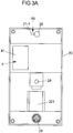
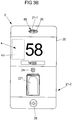
- the outdoor unit 2 as a design element on a display surface 23 for displaying the house number "58" and the name of the resident.
- a microphone 21-1 is provided as an acoustic communication interface.
- a movement sensor 26 for detecting movement in the vicinity of the outdoor unit 2 is further arranged in the upper area of the outdoor unit 2.
- a speaker 21-2 is provided for the acoustic communication.
- the Outdoor device 2 As an authentication interface 22 on a fingerprint scanner 221.
- biometric detection unit and / or, for example, an RFID reader may also be provided on the outdoor unit 2 as the authentication interface 22.
- an RFID reader may also be provided on the outdoor unit 2 as the authentication interface 22.
- a person and / or a security token can be authenticated and optionally checked for an access authorization to the interior area 52.
- a camera 24 serving as an optical communication interface for the communication.
- the camera 24 can be designed to take digital photos and / or videos.
- the outdoor unit 2 has on its front side in the lower area a signal actuating element 28 in the form of a bell button.
- An actuation of the bell button 28 can trigger, for example, a ring signal audible in the interior region 52 of the building 5.
- a signal function on the indoor unit 3 can be triggered upon actuation of the bell button 28.
- a trigger signal from the outdoor unit 2 to the indoor unit 3 can be wirelessly transmitted to trigger the signaling function.
- the triggering signal may, for example, transmit a push message to the resident's smartphone 3 in order to signal that a visitor to the door 9 desires admission to the interior area 52.
- the aforementioned elements of the outdoor unit 2 are all arranged in or on a housing 20 of the outdoor unit 2.
- the outdoor unit 2 can be arranged as a compact unit in the outdoor area 51, for example in the vicinity of the door 9.
- FIG. 3A shows an example of an interior view of an outdoor unit 2 according to the invention from the front with the housing 20 open, from which an advantageous arrangement of the aforementioned elements 21-1, 221, 26, 28, 4 can be seen.
- FIG. 3B a corresponding frontal view of the outdoor unit 2 FIG. 3A faced with the housing 20 closed.
- the outdoor unit 2 further comprises an electronic control device 4, which is designed to generate control signals 80 for controlling one or more presence simulation devices 8, in order to generate in one for one in Person perceptible to outdoor area 51 to simulate the presence of a person in interior area 52.
- an electronic control device 4 which is designed to generate control signals 80 for controlling one or more presence simulation devices 8, in order to generate in one for one in Person perceptible to outdoor area 51 to simulate the presence of a person in interior area 52.
- a plurality of electronically controllable devices 81, 82, 83, 84, 85 are provided as presence simulation devices 8.
- a lighting device 81, a power-operated shutter 82, a music system 83 and a television set 84 as presence simulation devices 8 are provided.
- the outdoor unit 2 has as an additional presence simulation device 8 an electronically controllable voice output 85.
- the electronically controllable voice output 85 can, as in the Fig. 1 to 3A illustrated, be arranged in the housing 20 of the outdoor unit 2.
- the electronic voice output 85 can be arranged, for example, in the area of the microphone 21 - 1 and / or of the motion sensor 26, as in FIGS Fig. 1 to 3A indicated.
- the electronic voice output 85 in the region of the loudspeaker 21-2 (cf. Fig. 1-3A ) or includes speaker 21-2 and uses for vocal playback of a stored voice message.
- the outdoor unit 2 has a transmission interface for wireless transmission of the control signals 80 to respective driving units of the presence simulation devices 81, 82, 83, 84 arranged in the interior area 52.
- the control signals 80 are generated by the electronic control unit 4 in response to a triggering event which is triggered by a in the outdoor area 51 person is triggered and detected by the outdoor unit 2.
- the triggering event may be a movement of an object in the vicinity of the outdoor unit 2, which is detected by the motion sensor 26.
- control device 4 may additionally or alternatively be arranged in the outdoor unit 2 at least partially in the indoor unit 3, as in FIG FIG. 1 shown.
- a control device 4 that is spatially separate from the outdoor unit 2 and the indoor unit 3 may be provided, which is preferably arranged in the inner area 52.
- a computer server (not shown) may be used as such a separate controller 4.
- a radio lock 91 Arranged on the door 9 is a radio lock 91, which can be actuated in response to a release signal 90 generated by the control device 4, around the door 9 open remotely.
- the enable signal 90 can be transmitted wirelessly from the electronic control device 4 to the radio lock 90.
- the enable signal 90 for the operation of the wireless lock 91 can be generated automatically by the electronic control device 4 when an authorized person and / or an authorized security token is detected at the fingerprint scanner 221 or at another authentication interface 22 of the outdoor device 2.
- the resident also has the option of generating a release signal 90 for opening the radio lock 91.
- the smartphone 3 may e.g. an application software be installed, which the inhabitant on a touch screen of the smartphone 3 a virtual button for operating the wireless lock 91, i. for generating and sending the enable signal 90.
- the motion sensor 26 When a visitor in the outer area 51 of the front door 9 - and thus the arranged near the front door 9 outdoor unit 2 - approaches - the movement of the visitor is detected by the motion sensor 26. This triggering event is detected by the control logic 41 of the electronic control device 4. As a result, the outdoor unit 2 wakes up from a stand-by mode, whereby the camera 24 is activated. In the dark, a lighting system for illuminating the vicinity of the outdoor unit 2 can additionally be activated automatically in order to enable image recordings of the visitor by means of the camera 24.
- the visitor If the visitor is entitled to access the interior area 51, he can identify himself at the fingerprint scanner 221 on the basis of a previously acquired fingerprint. Additionally or alternatively, an authentication by means of a security token on an RFID reader, which may be provided as an authentication interface 22 on the outdoor unit 2.
- the radio lock 91 After a successful authentication of an authorized person and / or an authorized security token, the radio lock 91 is automatically operated to open the front door 9.
- a release signal 90 for the operation of the wireless lock 91 is automatically generated by the electronic control device 4 and transmitted wirelessly to the wireless lock 91 when the fingerprint scanner 221 or at another authentication interface 22 of the outdoor unit 2 an authorized person and / or an authorized security token is detected.
- the visitor can actuate the bell button 28 and thereby trigger a ring signal audible in the interior area 52 of the building 5.
- a signal function on the indoor unit 3 is triggered.
- a trigger signal from the outdoor unit 2 to the indoor unit 3 can be wirelessly transmitted to trigger the signal function on the indoor unit 3.
- the trigger signal may, for example, transmit a push message to the resident's smartphone 3 to signal to the resident that a visitor is at the door 9 and desires entry into the interior area 52.
- a digital photo and / or video of the visitor is captured and wirelessly transmitted to the smartphone 3 to provide the occupant with a visual impression of the visitor.
- the smartphone 3 the wireless communication connection 7 and the outdoor unit 2, the resident can enter into a dialogue with the visitor, whereby 7 audio signals are transmitted via the respective acoustic and / or optical communication interfaces 21-1, 21-2, 31 and the wireless communication connection. and image data can be exchanged.
- a voice and / or image-based dialogue between the visitor and the resident can be installed on the smartphone 3, for example, a corresponding application software.
- the communication can also take place via a browser-based application, wherein a corresponding browser window is displayed on a touch screen of the smartphone 3.
- a release signal 90 for opening the radio lock 91 by manually inputting to the smartphone 3.
- the release signal 90 is generated by the control device 4 and transmitted wirelessly from the smartphone 3 to the wireless lock 91.
- a virtual button for actuating the radio lock 91 ie for generating and sending the enable signal 90, may be provided.
- At least one of the presence simulation devices 8, 81, 82, 83, 84, 85 is activated to detect the presence of a person in the indoor area in a manner perceptible to a person in the outdoor area 51 52 to simulate.
- the control device 4, the lighting device 81, the power-operated shutter 82, the music system 83 or the television 84 actuate.
- the lighting device 81, the music system 83 or the television 84 may be arranged in the inner region 52 such that they visually and / or acoustically perceptible into the outer region 51 into effect.
- the actuation of the presence simulation device 8 may in particular comprise the activation of the electronically controllable voice output 85 provided on the outdoor device 2.
- the electronically controllable voice output 85 a previously recorded voice message of the type "Can I help you?" to give an impression to a person in the outdoor area 51 that the indoor area 52 is currently occupied. An uninvited visitor can thus be deterred from undertaking a break-in attempt to the interior 51.
- the indoor unit 3 in the context of the door communication system 1 according to the invention can optionally be connected in a flexible manner to various "smart home" applications known per se from building automation technology.
- the indoor unit 3 for example, additionally used for arming or disarming an alarm system and / or for automated lighting, blinds, electricity and / or heating control.
- the indoor unit 3 can be used for health-related monitoring functions, e.g. relate to a room temperature, a room humidity or an oxygen, carbon dioxide and / or pollutant content of the room air.
- safety-related monitoring functions such as a smoke, fire alarm and / or broken glass alarm function can be integrated with the door communication system 1 via the indoor unit 3 and possibly a corresponding application software.
- the door communication system comprises further hardware components, in particular at least one sensor for the above-mentioned exemplary applications of the building automation technology.
- a sensor may include a transmitting device for sending sensor data to the outdoor unit 2 via a wireless communication link, e.g. Wireless, Bluetooth, ZigBee, Z-Wave and / or DECT.
- sensor data obtained in this way to the outdoor unit from there via the wireless communication link 7, e.g. via WLAN continue to be transmitted to the indoor unit 3.
- the indoor unit 3 can be, for example, a computer server with internet connection arranged in the interior area 52. In this way, a remote resident can remotely access "smart home" applications based on the sensor data.
- the door communication system may include at least one electronically controllable device of the building automation.
- An absent resident can get these out of the Control remotely, the control signals via the Internet, the computer server (as indoor unit), the wireless communication link 7 (eg WLAN), the outdoor unit and another wireless communication link (eg wireless, Bluetooth, ZigBee, Z-Wave and / or DECT ) between the outdoor unit 2 and the electronically controllable device.
- the outdoor unit 2 represents an interface for the "last mile" of the communication, which is bridged for example by radio, Bluetooth, ZigBee, Z-Wave and / or DECT.
- the indoor unit 3 is the interface for the remote communication, for example via the Internet, wherein the outdoor unit 2 and the indoor unit 3 can communicate with each other via the wireless communication link 7.
Landscapes
- Engineering & Computer Science (AREA)
- Signal Processing (AREA)
- Physics & Mathematics (AREA)
- General Physics & Mathematics (AREA)
- Multimedia (AREA)
- Lock And Its Accessories (AREA)
Priority Applications (1)
| Application Number | Priority Date | Filing Date | Title |
|---|---|---|---|
| PL17160809T PL3220617T3 (pl) | 2016-03-14 | 2017-03-14 | Układ komunikacji drzwiowej, urządzenie zewnętrzne do układu komunikacji drzwiowej i sposób działania układu komunikacji drzwiowej |
Applications Claiming Priority (1)
| Application Number | Priority Date | Filing Date | Title |
|---|---|---|---|
| DE102016204167.3A DE102016204167A1 (de) | 2016-03-14 | 2016-03-14 | Türkommunikationssystem, Außengerät für ein Türkommunikationssystem und Verfahren zum Betrieb eines Türkommunikationssystems |
Publications (2)
| Publication Number | Publication Date |
|---|---|
| EP3220617A1 true EP3220617A1 (fr) | 2017-09-20 |
| EP3220617B1 EP3220617B1 (fr) | 2019-01-09 |
Family
ID=58448296
Family Applications (1)
| Application Number | Title | Priority Date | Filing Date |
|---|---|---|---|
| EP17160809.4A Active EP3220617B1 (fr) | 2016-03-14 | 2017-03-14 | Système de communication de porte, appareil externe pour un système de communication de porte et procédé de fonctionnement d'un système de communication de porte |
Country Status (4)
| Country | Link |
|---|---|
| EP (1) | EP3220617B1 (fr) |
| DE (1) | DE102016204167A1 (fr) |
| DK (1) | DK3220617T3 (fr) |
| PL (1) | PL3220617T3 (fr) |
Cited By (1)
| Publication number | Priority date | Publication date | Assignee | Title |
|---|---|---|---|---|
| DE102021104286A1 (de) | 2020-02-24 | 2021-08-26 | Home - smart in use Gesellschaft mit beschränkter Haftung | System zum Installieren einer Klingel- und Gegensprechanlage mit Video- und Datenfernübertragungsfunktionalität für ein Mehrparteiengebäude |
Families Citing this family (1)
| Publication number | Priority date | Publication date | Assignee | Title |
|---|---|---|---|---|
| CN112737920B (zh) * | 2020-12-16 | 2022-10-04 | 交通运输部南海航海保障中心广州通信中心 | 一种基于音频能量检测的多方即时通信系统 |
Citations (3)
| Publication number | Priority date | Publication date | Assignee | Title |
|---|---|---|---|---|
| US20120001755A1 (en) * | 2010-07-02 | 2012-01-05 | Richard Paul Conrady | Virtual Presence after Security Event Detection |
| DE202012012542U1 (de) | 2012-04-16 | 2013-05-28 | Schneider Electric Industries Sas | Türsprechanlage |
| US9253455B1 (en) * | 2014-06-25 | 2016-02-02 | SkyBell Technologies, Inc. | Doorbell communication systems and methods |
Family Cites Families (6)
| Publication number | Priority date | Publication date | Assignee | Title |
|---|---|---|---|---|
| GB2202982A (en) * | 1987-03-27 | 1988-10-05 | Mercer Energy Conservation Com | Improvements in or relating to alarm systems |
| IT1306222B1 (it) * | 1996-12-09 | 2001-06-04 | Sideral Srl | Sistema di protezione e d'allarme anti-intrusione per ville, edificiper abitazione e lavoro, mediante apparecchi video in genere |
| US6069655A (en) * | 1997-08-01 | 2000-05-30 | Wells Fargo Alarm Services, Inc. | Advanced video security system |
| US8154581B2 (en) * | 2002-10-15 | 2012-04-10 | Revolutionary Concepts, Inc. | Audio-video communication system for receiving person at entrance |
| US7583191B2 (en) * | 2006-11-14 | 2009-09-01 | Zinser Duke W | Security system and method for use of same |
| DE202011110280U1 (de) * | 2011-12-20 | 2013-04-30 | Telegärtner GmbH | Türsprechanlage |
-
2016
- 2016-03-14 DE DE102016204167.3A patent/DE102016204167A1/de not_active Ceased
-
2017
- 2017-03-14 DK DK17160809.4T patent/DK3220617T3/en active
- 2017-03-14 EP EP17160809.4A patent/EP3220617B1/fr active Active
- 2017-03-14 PL PL17160809T patent/PL3220617T3/pl unknown
Patent Citations (3)
| Publication number | Priority date | Publication date | Assignee | Title |
|---|---|---|---|---|
| US20120001755A1 (en) * | 2010-07-02 | 2012-01-05 | Richard Paul Conrady | Virtual Presence after Security Event Detection |
| DE202012012542U1 (de) | 2012-04-16 | 2013-05-28 | Schneider Electric Industries Sas | Türsprechanlage |
| US9253455B1 (en) * | 2014-06-25 | 2016-02-02 | SkyBell Technologies, Inc. | Doorbell communication systems and methods |
Non-Patent Citations (2)
| Title |
|---|
| "Building the home of the future - today;HFDH_14 Laurent_Nicq_ConvergeX", ETSI DRAFT; HFDH_14 LAURENT_NICQ_CONVERGEX, EUROPEAN TELECOMMUNICATIONS STANDARDS INSTITUTE (ETSI), 650, ROUTE DES LUCIOLES ; F-06921 SOPHIA-ANTIPOLIS ; FRANCE, vol. HF - Open, 22 October 2004 (2004-10-22), pages 1 - 19, XP014211251 * |
| DIDIER DONSEZ ET AL: "A Multi-Protocol Service-Oriented Platform for Home Control Applications", CONSUMER COMMUNICATIONS AND NETWORKING CONFERENCE, 2007. CCNC 2007. 20 07 4TH IEEE, IEEE, PI, 1 January 2007 (2007-01-01), pages 1174 - 1175, XP031087970, ISBN: 978-1-4244-0667-8 * |
Cited By (1)
| Publication number | Priority date | Publication date | Assignee | Title |
|---|---|---|---|---|
| DE102021104286A1 (de) | 2020-02-24 | 2021-08-26 | Home - smart in use Gesellschaft mit beschränkter Haftung | System zum Installieren einer Klingel- und Gegensprechanlage mit Video- und Datenfernübertragungsfunktionalität für ein Mehrparteiengebäude |
Also Published As
| Publication number | Publication date |
|---|---|
| EP3220617B1 (fr) | 2019-01-09 |
| DE102016204167A1 (de) | 2017-09-14 |
| PL3220617T3 (pl) | 2019-07-31 |
| DK3220617T3 (en) | 2019-04-23 |
Similar Documents
| Publication | Publication Date | Title |
|---|---|---|
| EP3295436B1 (fr) | Procédé d'utilisation d'un appareil de nettoyage à déplacement autonome | |
| EP3610465B1 (fr) | Système de contrôle d'accès avec reconnaissance faciale et radioélectrique | |
| EP3610466B1 (fr) | Procédé d'enregistrement et de contrôle d'accès de visiteurs | |
| EP3212554B1 (fr) | Système et procédé de préservation de la sphère privée de personnes dans des systèmes d'ascenseur | |
| DE102007059934B4 (de) | Hauskommunikationssystem mit Türstation | |
| EP3729384B1 (fr) | Système de contrôle d'accès avec reconnaissance faciale et radioélectrique | |
| EP2608511A1 (fr) | Interphone de porte et procédé de fonctionnement d'un interphone de porte | |
| ITTV20110153A1 (it) | Sistema di videocitofonia | |
| DE102014207737A1 (de) | Verfahren zum Betreiben eines Haushaltsgeräts mit spezifischer Nutzeridentifikation sowie Haushaltsgerät und System mit einem Haushaltsgerät | |
| AU2020391477B2 (en) | Accessibility features for monitoring systems | |
| EP2642457A2 (fr) | Procédé et système destinés à la réalisation dýun contrôle d'accès à un bâtiment | |
| EP3007139B1 (fr) | Systeme de fermeture de porte | |
| EP3220617B1 (fr) | Système de communication de porte, appareil externe pour un système de communication de porte et procédé de fonctionnement d'un système de communication de porte | |
| EP3096299B1 (fr) | Installation de fermeture et procédé de fonctionnement d'une installation de fermeture pour une porte de batiment | |
| EP2091023B1 (fr) | Procédé de génération d'un signal d'information lors d'un souhait d'accès et dispositif d'exécution du procédé | |
| DE102016108013B3 (de) | Verfahren für ein System zum sicheren Öffnen einer Türe sowie System zum sicheren Öffnen einer Türe | |
| EP3748590A1 (fr) | Appareil d'authentification pouvant être monté au mur | |
| WO2021121989A1 (fr) | Système de bâtiment pour une communication d'utilisateur privée | |
| EP3133570A2 (fr) | Systeme de detecteur de fumee ayant une fonctionnalite d'alarme a detection de presence | |
| DE202017006423U1 (de) | Smart Home Haustür | |
| EP4452811A1 (fr) | Système d'ascenseur ayant des règles d'utilisation d'ascenseur au niveau d'une ouverture de porte de bâtiment | |
| DE19950799B4 (de) | Türanlage | |
| EP2667602B1 (fr) | Système de communication interne doté d'au moins une station de porte et de plusieurs stations d'habitation | |
| EP3929885A1 (fr) | Procédé de domotique | |
| EP2966625B1 (fr) | Dispositif de controle d'acces |
Legal Events
| Date | Code | Title | Description |
|---|---|---|---|
| PUAI | Public reference made under article 153(3) epc to a published international application that has entered the european phase |
Free format text: ORIGINAL CODE: 0009012 |
|
| STAA | Information on the status of an ep patent application or granted ep patent |
Free format text: STATUS: THE APPLICATION HAS BEEN PUBLISHED |
|
| AK | Designated contracting states |
Kind code of ref document: A1 Designated state(s): AL AT BE BG CH CY CZ DE DK EE ES FI FR GB GR HR HU IE IS IT LI LT LU LV MC MK MT NL NO PL PT RO RS SE SI SK SM TR |
|
| AX | Request for extension of the european patent |
Extension state: BA ME |
|
| STAA | Information on the status of an ep patent application or granted ep patent |
Free format text: STATUS: REQUEST FOR EXAMINATION WAS MADE |
|
| 17P | Request for examination filed |
Effective date: 20180320 |
|
| RBV | Designated contracting states (corrected) |
Designated state(s): AL AT BE BG CH CY CZ DE DK EE ES FI FR GB GR HR HU IE IS IT LI LT LU LV MC MK MT NL NO PL PT RO RS SE SI SK SM TR |
|
| GRAP | Despatch of communication of intention to grant a patent |
Free format text: ORIGINAL CODE: EPIDOSNIGR1 |
|
| STAA | Information on the status of an ep patent application or granted ep patent |
Free format text: STATUS: GRANT OF PATENT IS INTENDED |
|
| INTG | Intention to grant announced |
Effective date: 20180925 |
|
| GRAS | Grant fee paid |
Free format text: ORIGINAL CODE: EPIDOSNIGR3 |
|
| GRAA | (expected) grant |
Free format text: ORIGINAL CODE: 0009210 |
|
| STAA | Information on the status of an ep patent application or granted ep patent |
Free format text: STATUS: THE PATENT HAS BEEN GRANTED |
|
| AK | Designated contracting states |
Kind code of ref document: B1 Designated state(s): AL AT BE BG CH CY CZ DE DK EE ES FI FR GB GR HR HU IE IS IT LI LT LU LV MC MK MT NL NO PL PT RO RS SE SI SK SM TR |
|
| REG | Reference to a national code |
Ref country code: GB Ref legal event code: FG4D Free format text: NOT ENGLISH |
|
| REG | Reference to a national code |
Ref country code: CH Ref legal event code: EP Ref country code: AT Ref legal event code: REF Ref document number: 1088764 Country of ref document: AT Kind code of ref document: T Effective date: 20190115 |
|
| REG | Reference to a national code |
Ref country code: IE Ref legal event code: FG4D Free format text: LANGUAGE OF EP DOCUMENT: GERMAN |
|
| REG | Reference to a national code |
Ref country code: DE Ref legal event code: R096 Ref document number: 502017000628 Country of ref document: DE |
|
| REG | Reference to a national code |
Ref country code: CH Ref legal event code: NV Representative=s name: SERVOPATENT GMBH, CH |
|
| REG | Reference to a national code |
Ref country code: DK Ref legal event code: T3 Effective date: 20190415 Ref country code: SE Ref legal event code: TRGR |
|
| REG | Reference to a national code |
Ref country code: NL Ref legal event code: FP |
|
| REG | Reference to a national code |
Ref country code: LT Ref legal event code: MG4D |
|
| PG25 | Lapsed in a contracting state [announced via postgrant information from national office to epo] |
Ref country code: NO Free format text: LAPSE BECAUSE OF FAILURE TO SUBMIT A TRANSLATION OF THE DESCRIPTION OR TO PAY THE FEE WITHIN THE PRESCRIBED TIME-LIMIT Effective date: 20190409 Ref country code: FI Free format text: LAPSE BECAUSE OF FAILURE TO SUBMIT A TRANSLATION OF THE DESCRIPTION OR TO PAY THE FEE WITHIN THE PRESCRIBED TIME-LIMIT Effective date: 20190109 Ref country code: PT Free format text: LAPSE BECAUSE OF FAILURE TO SUBMIT A TRANSLATION OF THE DESCRIPTION OR TO PAY THE FEE WITHIN THE PRESCRIBED TIME-LIMIT Effective date: 20190509 Ref country code: LT Free format text: LAPSE BECAUSE OF FAILURE TO SUBMIT A TRANSLATION OF THE DESCRIPTION OR TO PAY THE FEE WITHIN THE PRESCRIBED TIME-LIMIT Effective date: 20190109 Ref country code: ES Free format text: LAPSE BECAUSE OF FAILURE TO SUBMIT A TRANSLATION OF THE DESCRIPTION OR TO PAY THE FEE WITHIN THE PRESCRIBED TIME-LIMIT Effective date: 20190109 |
|
| PG25 | Lapsed in a contracting state [announced via postgrant information from national office to epo] |
Ref country code: RS Free format text: LAPSE BECAUSE OF FAILURE TO SUBMIT A TRANSLATION OF THE DESCRIPTION OR TO PAY THE FEE WITHIN THE PRESCRIBED TIME-LIMIT Effective date: 20190109 Ref country code: LV Free format text: LAPSE BECAUSE OF FAILURE TO SUBMIT A TRANSLATION OF THE DESCRIPTION OR TO PAY THE FEE WITHIN THE PRESCRIBED TIME-LIMIT Effective date: 20190109 Ref country code: HR Free format text: LAPSE BECAUSE OF FAILURE TO SUBMIT A TRANSLATION OF THE DESCRIPTION OR TO PAY THE FEE WITHIN THE PRESCRIBED TIME-LIMIT Effective date: 20190109 Ref country code: IS Free format text: LAPSE BECAUSE OF FAILURE TO SUBMIT A TRANSLATION OF THE DESCRIPTION OR TO PAY THE FEE WITHIN THE PRESCRIBED TIME-LIMIT Effective date: 20190509 Ref country code: BG Free format text: LAPSE BECAUSE OF FAILURE TO SUBMIT A TRANSLATION OF THE DESCRIPTION OR TO PAY THE FEE WITHIN THE PRESCRIBED TIME-LIMIT Effective date: 20190409 Ref country code: GR Free format text: LAPSE BECAUSE OF FAILURE TO SUBMIT A TRANSLATION OF THE DESCRIPTION OR TO PAY THE FEE WITHIN THE PRESCRIBED TIME-LIMIT Effective date: 20190410 |
|
| REG | Reference to a national code |
Ref country code: DE Ref legal event code: R097 Ref document number: 502017000628 Country of ref document: DE |
|
| PG25 | Lapsed in a contracting state [announced via postgrant information from national office to epo] |
Ref country code: EE Free format text: LAPSE BECAUSE OF FAILURE TO SUBMIT A TRANSLATION OF THE DESCRIPTION OR TO PAY THE FEE WITHIN THE PRESCRIBED TIME-LIMIT Effective date: 20190109 Ref country code: CZ Free format text: LAPSE BECAUSE OF FAILURE TO SUBMIT A TRANSLATION OF THE DESCRIPTION OR TO PAY THE FEE WITHIN THE PRESCRIBED TIME-LIMIT Effective date: 20190109 Ref country code: RO Free format text: LAPSE BECAUSE OF FAILURE TO SUBMIT A TRANSLATION OF THE DESCRIPTION OR TO PAY THE FEE WITHIN THE PRESCRIBED TIME-LIMIT Effective date: 20190109 Ref country code: IT Free format text: LAPSE BECAUSE OF FAILURE TO SUBMIT A TRANSLATION OF THE DESCRIPTION OR TO PAY THE FEE WITHIN THE PRESCRIBED TIME-LIMIT Effective date: 20190109 Ref country code: SK Free format text: LAPSE BECAUSE OF FAILURE TO SUBMIT A TRANSLATION OF THE DESCRIPTION OR TO PAY THE FEE WITHIN THE PRESCRIBED TIME-LIMIT Effective date: 20190109 Ref country code: MC Free format text: LAPSE BECAUSE OF FAILURE TO SUBMIT A TRANSLATION OF THE DESCRIPTION OR TO PAY THE FEE WITHIN THE PRESCRIBED TIME-LIMIT Effective date: 20190109 Ref country code: AL Free format text: LAPSE BECAUSE OF FAILURE TO SUBMIT A TRANSLATION OF THE DESCRIPTION OR TO PAY THE FEE WITHIN THE PRESCRIBED TIME-LIMIT Effective date: 20190109 |
|
| PLBE | No opposition filed within time limit |
Free format text: ORIGINAL CODE: 0009261 |
|
| STAA | Information on the status of an ep patent application or granted ep patent |
Free format text: STATUS: NO OPPOSITION FILED WITHIN TIME LIMIT |
|
| 26N | No opposition filed |
Effective date: 20191010 |
|
| PG25 | Lapsed in a contracting state [announced via postgrant information from national office to epo] |
Ref country code: IE Free format text: LAPSE BECAUSE OF NON-PAYMENT OF DUE FEES Effective date: 20190314 |
|
| PG25 | Lapsed in a contracting state [announced via postgrant information from national office to epo] |
Ref country code: SI Free format text: LAPSE BECAUSE OF FAILURE TO SUBMIT A TRANSLATION OF THE DESCRIPTION OR TO PAY THE FEE WITHIN THE PRESCRIBED TIME-LIMIT Effective date: 20190109 |
|
| PG25 | Lapsed in a contracting state [announced via postgrant information from national office to epo] |
Ref country code: TR Free format text: LAPSE BECAUSE OF FAILURE TO SUBMIT A TRANSLATION OF THE DESCRIPTION OR TO PAY THE FEE WITHIN THE PRESCRIBED TIME-LIMIT Effective date: 20190109 |
|
| REG | Reference to a national code |
Ref country code: CH Ref legal event code: PCAR Free format text: NEW ADDRESS: WANNERSTRASSE 9/1, 8045 ZUERICH (CH) |
|
| PG25 | Lapsed in a contracting state [announced via postgrant information from national office to epo] |
Ref country code: MT Free format text: LAPSE BECAUSE OF FAILURE TO SUBMIT A TRANSLATION OF THE DESCRIPTION OR TO PAY THE FEE WITHIN THE PRESCRIBED TIME-LIMIT Effective date: 20190109 |
|
| PG25 | Lapsed in a contracting state [announced via postgrant information from national office to epo] |
Ref country code: CY Free format text: LAPSE BECAUSE OF FAILURE TO SUBMIT A TRANSLATION OF THE DESCRIPTION OR TO PAY THE FEE WITHIN THE PRESCRIBED TIME-LIMIT Effective date: 20190109 |
|
| PG25 | Lapsed in a contracting state [announced via postgrant information from national office to epo] |
Ref country code: SM Free format text: LAPSE BECAUSE OF FAILURE TO SUBMIT A TRANSLATION OF THE DESCRIPTION OR TO PAY THE FEE WITHIN THE PRESCRIBED TIME-LIMIT Effective date: 20190109 |
|
| PG25 | Lapsed in a contracting state [announced via postgrant information from national office to epo] |
Ref country code: HU Free format text: LAPSE BECAUSE OF FAILURE TO SUBMIT A TRANSLATION OF THE DESCRIPTION OR TO PAY THE FEE WITHIN THE PRESCRIBED TIME-LIMIT; INVALID AB INITIO Effective date: 20170314 |
|
| PGFP | Annual fee paid to national office [announced via postgrant information from national office to epo] |
Ref country code: GB Payment date: 20220324 Year of fee payment: 6 Ref country code: DK Payment date: 20220322 Year of fee payment: 6 |
|
| PGFP | Annual fee paid to national office [announced via postgrant information from national office to epo] |
Ref country code: SE Payment date: 20220324 Year of fee payment: 6 Ref country code: PL Payment date: 20220126 Year of fee payment: 6 Ref country code: NL Payment date: 20220322 Year of fee payment: 6 Ref country code: LU Payment date: 20220322 Year of fee payment: 6 Ref country code: FR Payment date: 20220323 Year of fee payment: 6 Ref country code: BE Payment date: 20220322 Year of fee payment: 6 |
|
| PG25 | Lapsed in a contracting state [announced via postgrant information from national office to epo] |
Ref country code: MK Free format text: LAPSE BECAUSE OF FAILURE TO SUBMIT A TRANSLATION OF THE DESCRIPTION OR TO PAY THE FEE WITHIN THE PRESCRIBED TIME-LIMIT Effective date: 20190109 |
|
| PGFP | Annual fee paid to national office [announced via postgrant information from national office to epo] |
Ref country code: AT Payment date: 20230317 Year of fee payment: 7 |
|
| PGFP | Annual fee paid to national office [announced via postgrant information from national office to epo] |
Ref country code: CH Payment date: 20230402 Year of fee payment: 7 |
|
| REG | Reference to a national code |
Ref country code: SE Ref legal event code: EUG |
|
| REG | Reference to a national code |
Ref country code: DK Ref legal event code: EBP Effective date: 20230331 |
|
| REG | Reference to a national code |
Ref country code: NL Ref legal event code: MM Effective date: 20230401 |
|
| GBPC | Gb: european patent ceased through non-payment of renewal fee |
Effective date: 20230314 |
|
| REG | Reference to a national code |
Ref country code: BE Ref legal event code: MM Effective date: 20230331 |
|
| PG25 | Lapsed in a contracting state [announced via postgrant information from national office to epo] |
Ref country code: NL Free format text: LAPSE BECAUSE OF NON-PAYMENT OF DUE FEES Effective date: 20230401 Ref country code: LU Free format text: LAPSE BECAUSE OF NON-PAYMENT OF DUE FEES Effective date: 20230314 |
|
| PG25 | Lapsed in a contracting state [announced via postgrant information from national office to epo] |
Ref country code: GB Free format text: LAPSE BECAUSE OF NON-PAYMENT OF DUE FEES Effective date: 20230314 |
|
| PG25 | Lapsed in a contracting state [announced via postgrant information from national office to epo] |
Ref country code: SE Free format text: LAPSE BECAUSE OF NON-PAYMENT OF DUE FEES Effective date: 20230315 Ref country code: GB Free format text: LAPSE BECAUSE OF NON-PAYMENT OF DUE FEES Effective date: 20230314 Ref country code: FR Free format text: LAPSE BECAUSE OF NON-PAYMENT OF DUE FEES Effective date: 20230331 |
|
| PG25 | Lapsed in a contracting state [announced via postgrant information from national office to epo] |
Ref country code: BE Free format text: LAPSE BECAUSE OF NON-PAYMENT OF DUE FEES Effective date: 20230331 |
|
| PG25 | Lapsed in a contracting state [announced via postgrant information from national office to epo] |
Ref country code: DK Free format text: LAPSE BECAUSE OF NON-PAYMENT OF DUE FEES Effective date: 20230331 |
|
| PG25 | Lapsed in a contracting state [announced via postgrant information from national office to epo] |
Ref country code: PL Free format text: LAPSE BECAUSE OF NON-PAYMENT OF DUE FEES Effective date: 20230314 |
|
| PG25 | Lapsed in a contracting state [announced via postgrant information from national office to epo] |
Ref country code: PL Free format text: LAPSE BECAUSE OF NON-PAYMENT OF DUE FEES Effective date: 20230314 |
|
| REG | Reference to a national code |
Ref country code: CH Ref legal event code: PL |
|
| REG | Reference to a national code |
Ref country code: AT Ref legal event code: MM01 Ref document number: 1088764 Country of ref document: AT Kind code of ref document: T Effective date: 20240314 |
|
| PG25 | Lapsed in a contracting state [announced via postgrant information from national office to epo] |
Ref country code: AT Free format text: LAPSE BECAUSE OF NON-PAYMENT OF DUE FEES Effective date: 20240314 |
|
| PG25 | Lapsed in a contracting state [announced via postgrant information from national office to epo] |
Ref country code: AT Free format text: LAPSE BECAUSE OF NON-PAYMENT OF DUE FEES Effective date: 20240314 Ref country code: CH Free format text: LAPSE BECAUSE OF NON-PAYMENT OF DUE FEES Effective date: 20240331 |
|
| PGFP | Annual fee paid to national office [announced via postgrant information from national office to epo] |
Ref country code: DE Payment date: 20260209 Year of fee payment: 10 |