EP3312930A1 - Resonance type non-contact charging device - Google Patents
Resonance type non-contact charging device Download PDFInfo
- Publication number
- EP3312930A1 EP3312930A1 EP17207402.3A EP17207402A EP3312930A1 EP 3312930 A1 EP3312930 A1 EP 3312930A1 EP 17207402 A EP17207402 A EP 17207402A EP 3312930 A1 EP3312930 A1 EP 3312930A1
- Authority
- EP
- European Patent Office
- Prior art keywords
- resonant coil
- side resonant
- power source
- high frequency
- charging
- Prior art date
- Legal status (The legal status is an assumption and is not a legal conclusion. Google has not performed a legal analysis and makes no representation as to the accuracy of the status listed.)
- Withdrawn
Links
Images


Classifications
-
- B—PERFORMING OPERATIONS; TRANSPORTING
- B60—VEHICLES IN GENERAL
- B60L—PROPULSION OF ELECTRICALLY-PROPELLED VEHICLES; SUPPLYING ELECTRIC POWER FOR AUXILIARY EQUIPMENT OF ELECTRICALLY-PROPELLED VEHICLES; ELECTRODYNAMIC BRAKE SYSTEMS FOR VEHICLES IN GENERAL; MAGNETIC SUSPENSION OR LEVITATION FOR VEHICLES; MONITORING OPERATING VARIABLES OF ELECTRICALLY-PROPELLED VEHICLES; ELECTRIC SAFETY DEVICES FOR ELECTRICALLY-PROPELLED VEHICLES
- B60L53/00—Methods of charging batteries, specially adapted for electric vehicles; Charging stations or on-board charging equipment therefor; Exchange of energy storage elements in electric vehicles
- B60L53/10—Methods of charging batteries, specially adapted for electric vehicles; Charging stations or on-board charging equipment therefor; Exchange of energy storage elements in electric vehicles characterised by the energy transfer between the charging station and the vehicle
- B60L53/12—Inductive energy transfer
-
- H—ELECTRICITY
- H01—ELECTRIC ELEMENTS
- H01M—PROCESSES OR MEANS, e.g. BATTERIES, FOR THE DIRECT CONVERSION OF CHEMICAL ENERGY INTO ELECTRICAL ENERGY
- H01M10/00—Secondary cells; Manufacture thereof
- H01M10/42—Methods or arrangements for servicing or maintenance of secondary cells or secondary half-cells
- H01M10/46—Accumulators structurally combined with charging apparatus
-
- B—PERFORMING OPERATIONS; TRANSPORTING
- B60—VEHICLES IN GENERAL
- B60L—PROPULSION OF ELECTRICALLY-PROPELLED VEHICLES; SUPPLYING ELECTRIC POWER FOR AUXILIARY EQUIPMENT OF ELECTRICALLY-PROPELLED VEHICLES; ELECTRODYNAMIC BRAKE SYSTEMS FOR VEHICLES IN GENERAL; MAGNETIC SUSPENSION OR LEVITATION FOR VEHICLES; MONITORING OPERATING VARIABLES OF ELECTRICALLY-PROPELLED VEHICLES; ELECTRIC SAFETY DEVICES FOR ELECTRICALLY-PROPELLED VEHICLES
- B60L53/00—Methods of charging batteries, specially adapted for electric vehicles; Charging stations or on-board charging equipment therefor; Exchange of energy storage elements in electric vehicles
- B60L53/10—Methods of charging batteries, specially adapted for electric vehicles; Charging stations or on-board charging equipment therefor; Exchange of energy storage elements in electric vehicles characterised by the energy transfer between the charging station and the vehicle
- B60L53/12—Inductive energy transfer
- B60L53/122—Circuits or methods for driving the primary coil, e.g. supplying electric power to the coil
-
- B—PERFORMING OPERATIONS; TRANSPORTING
- B60—VEHICLES IN GENERAL
- B60L—PROPULSION OF ELECTRICALLY-PROPELLED VEHICLES; SUPPLYING ELECTRIC POWER FOR AUXILIARY EQUIPMENT OF ELECTRICALLY-PROPELLED VEHICLES; ELECTRODYNAMIC BRAKE SYSTEMS FOR VEHICLES IN GENERAL; MAGNETIC SUSPENSION OR LEVITATION FOR VEHICLES; MONITORING OPERATING VARIABLES OF ELECTRICALLY-PROPELLED VEHICLES; ELECTRIC SAFETY DEVICES FOR ELECTRICALLY-PROPELLED VEHICLES
- B60L53/00—Methods of charging batteries, specially adapted for electric vehicles; Charging stations or on-board charging equipment therefor; Exchange of energy storage elements in electric vehicles
- B60L53/10—Methods of charging batteries, specially adapted for electric vehicles; Charging stations or on-board charging equipment therefor; Exchange of energy storage elements in electric vehicles characterised by the energy transfer between the charging station and the vehicle
- B60L53/12—Inductive energy transfer
- B60L53/126—Methods for pairing a vehicle and a charging station, e.g. establishing a one-to-one relation between a wireless power transmitter and a wireless power receiver
-
- H—ELECTRICITY
- H01—ELECTRIC ELEMENTS
- H01M—PROCESSES OR MEANS, e.g. BATTERIES, FOR THE DIRECT CONVERSION OF CHEMICAL ENERGY INTO ELECTRICAL ENERGY
- H01M10/00—Secondary cells; Manufacture thereof
- H01M10/42—Methods or arrangements for servicing or maintenance of secondary cells or secondary half-cells
- H01M10/44—Methods for charging or discharging
-
- H—ELECTRICITY
- H02—GENERATION; CONVERSION OR DISTRIBUTION OF ELECTRIC POWER
- H02J—ELECTRIC POWER NETWORKS; CIRCUIT ARRANGEMENTS OR SYSTEMS FOR SUPPLYING OR DISTRIBUTING ELECTRIC POWER; SYSTEMS FOR STORING ELECTRIC ENERGY
- H02J50/00—Circuit arrangements or systems for wireless supply or distribution of electric power
- H02J50/10—Circuit arrangements or systems for wireless supply or distribution of electric power using inductive coupling
- H02J50/12—Circuit arrangements or systems for wireless supply or distribution of electric power using inductive coupling of the resonant type
-
- H—ELECTRICITY
- H02—GENERATION; CONVERSION OR DISTRIBUTION OF ELECTRIC POWER
- H02J—ELECTRIC POWER NETWORKS; CIRCUIT ARRANGEMENTS OR SYSTEMS FOR SUPPLYING OR DISTRIBUTING ELECTRIC POWER; SYSTEMS FOR STORING ELECTRIC ENERGY
- H02J50/00—Circuit arrangements or systems for wireless supply or distribution of electric power
- H02J50/80—Circuit arrangements or systems for wireless supply or distribution of electric power involving the exchange of data, concerning supply or distribution of electric power, between transmitting devices and receiving devices
-
- H—ELECTRICITY
- H02—GENERATION; CONVERSION OR DISTRIBUTION OF ELECTRIC POWER
- H02J—ELECTRIC POWER NETWORKS; CIRCUIT ARRANGEMENTS OR SYSTEMS FOR SUPPLYING OR DISTRIBUTING ELECTRIC POWER; SYSTEMS FOR STORING ELECTRIC ENERGY
- H02J7/00—Circuit arrangements for charging or discharging batteries or for supplying loads from batteries
- H02J7/40—Circuit arrangements for charging or discharging batteries or for supplying loads from batteries characterised by the exchange of charge or discharge related data
- H02J7/42—Circuit arrangements for charging or discharging batteries or for supplying loads from batteries characterised by the exchange of charge or discharge related data with electronic devices having internal batteries, e.g. mobile phones
-
- H—ELECTRICITY
- H01—ELECTRIC ELEMENTS
- H01M—PROCESSES OR MEANS, e.g. BATTERIES, FOR THE DIRECT CONVERSION OF CHEMICAL ENERGY INTO ELECTRICAL ENERGY
- H01M2220/00—Batteries for particular applications
- H01M2220/20—Batteries in motive systems, e.g. vehicle, ship, plane
-
- Y—GENERAL TAGGING OF NEW TECHNOLOGICAL DEVELOPMENTS; GENERAL TAGGING OF CROSS-SECTIONAL TECHNOLOGIES SPANNING OVER SEVERAL SECTIONS OF THE IPC; TECHNICAL SUBJECTS COVERED BY FORMER USPC CROSS-REFERENCE ART COLLECTIONS [XRACs] AND DIGESTS
- Y02—TECHNOLOGIES OR APPLICATIONS FOR MITIGATION OR ADAPTATION AGAINST CLIMATE CHANGE
- Y02E—REDUCTION OF GREENHOUSE GAS [GHG] EMISSIONS, RELATED TO ENERGY GENERATION, TRANSMISSION OR DISTRIBUTION
- Y02E60/00—Enabling technologies; Technologies with a potential or indirect contribution to GHG emissions mitigation
- Y02E60/10—Energy storage using batteries
-
- Y—GENERAL TAGGING OF NEW TECHNOLOGICAL DEVELOPMENTS; GENERAL TAGGING OF CROSS-SECTIONAL TECHNOLOGIES SPANNING OVER SEVERAL SECTIONS OF THE IPC; TECHNICAL SUBJECTS COVERED BY FORMER USPC CROSS-REFERENCE ART COLLECTIONS [XRACs] AND DIGESTS
- Y02—TECHNOLOGIES OR APPLICATIONS FOR MITIGATION OR ADAPTATION AGAINST CLIMATE CHANGE
- Y02T—CLIMATE CHANGE MITIGATION TECHNOLOGIES RELATED TO TRANSPORTATION
- Y02T10/00—Road transport of goods or passengers
- Y02T10/60—Other road transportation technologies with climate change mitigation effect
- Y02T10/70—Energy storage systems for electromobility, e.g. batteries
-
- Y—GENERAL TAGGING OF NEW TECHNOLOGICAL DEVELOPMENTS; GENERAL TAGGING OF CROSS-SECTIONAL TECHNOLOGIES SPANNING OVER SEVERAL SECTIONS OF THE IPC; TECHNICAL SUBJECTS COVERED BY FORMER USPC CROSS-REFERENCE ART COLLECTIONS [XRACs] AND DIGESTS
- Y02—TECHNOLOGIES OR APPLICATIONS FOR MITIGATION OR ADAPTATION AGAINST CLIMATE CHANGE
- Y02T—CLIMATE CHANGE MITIGATION TECHNOLOGIES RELATED TO TRANSPORTATION
- Y02T10/00—Road transport of goods or passengers
- Y02T10/60—Other road transportation technologies with climate change mitigation effect
- Y02T10/7072—Electromobility specific charging systems or methods for batteries, ultracapacitors, supercapacitors or double-layer capacitors
-
- Y—GENERAL TAGGING OF NEW TECHNOLOGICAL DEVELOPMENTS; GENERAL TAGGING OF CROSS-SECTIONAL TECHNOLOGIES SPANNING OVER SEVERAL SECTIONS OF THE IPC; TECHNICAL SUBJECTS COVERED BY FORMER USPC CROSS-REFERENCE ART COLLECTIONS [XRACs] AND DIGESTS
- Y02—TECHNOLOGIES OR APPLICATIONS FOR MITIGATION OR ADAPTATION AGAINST CLIMATE CHANGE
- Y02T—CLIMATE CHANGE MITIGATION TECHNOLOGIES RELATED TO TRANSPORTATION
- Y02T90/00—Enabling technologies or technologies with a potential or indirect contribution to GHG emissions mitigation
- Y02T90/10—Technologies relating to charging of electric vehicles
- Y02T90/12—Electric charging stations
-
- Y—GENERAL TAGGING OF NEW TECHNOLOGICAL DEVELOPMENTS; GENERAL TAGGING OF CROSS-SECTIONAL TECHNOLOGIES SPANNING OVER SEVERAL SECTIONS OF THE IPC; TECHNICAL SUBJECTS COVERED BY FORMER USPC CROSS-REFERENCE ART COLLECTIONS [XRACs] AND DIGESTS
- Y02—TECHNOLOGIES OR APPLICATIONS FOR MITIGATION OR ADAPTATION AGAINST CLIMATE CHANGE
- Y02T—CLIMATE CHANGE MITIGATION TECHNOLOGIES RELATED TO TRANSPORTATION
- Y02T90/00—Enabling technologies or technologies with a potential or indirect contribution to GHG emissions mitigation
- Y02T90/10—Technologies relating to charging of electric vehicles
- Y02T90/14—Plug-in electric vehicles
Definitions
- the present invention relates to a resonance type non-contact charging device.
- Patent Document 1 discloses a power transmission system of the resonance scheme transmitting electric power wirelessly from a primary side resonant coil at the power transmission side towards a secondary side resonant coil at the power reception side arranged apart from the primary side resonant coil.
- development of an AC electric field by the primary side resonant coil through the AC voltage from a high frequency power source causes development of an oscillating magnetic field in the proximity of the primary side resonant coil. Electric power is transferred from the primary side resonant coil to the secondary side resonant coil by a resonance phenomenon.
- Patent Document 1 WO/2007/008646
- a high frequency power source and a primary side resonant coil must be provided at the power transmission side, whereas a secondary side resonant coil and a charger must be provided at the power reception side. Since the power transmission system is of the high frequency transmission scheme, stopping the charger before stopping the high frequency power source will cause a portion of or all of the power transmitted from the primary side resonant coil to the secondary side resonant coil to be reflected towards the high frequency power source, leading to the possibility of the high frequency power source being damaged. Moreover, stopping the charger before stopping the high frequency power source will cause sudden increase in the input voltage to the charger (output voltage of the resonance system), leading to the possibility of the charger being damaged.
- An object of the present invention is to provide a resonance type non-contact charging device that can prevent incurring damage when charging is stopped.
- a resonance type non-contact charging device includes a high frequency power source, a primary side resonant coil, a secondary side resonant coil, a charger, a secondary battery, and a stop control unit.
- the primary side resonant coil receives supply of high frequency electric power from the high frequency power source.
- the secondary side resonant coil is arranged apart from the primary side resonant coil in a non-contact manner.
- the secondary side resonant coil receives electric power from the primary side resonant coil through the magnetic field resonance between the primary side resonant coil and secondary side resonant coil.
- the charger receives supply of high frequency electric power from the secondary side resonant coil.
- the secondary battery is connected to the charger.
- the stop control unit stops the high frequency power source before stopping the charger when charging is to be stopped.
- a resonance type non-contact charging device according to an embodiment of the present invention will be described hereinafter according to Figs. 1-3 .
- the resonance type non-contact charging device of the present embodiment is applied to a charging system for a battery (secondary battery) mounted on a hybrid vehicle, i.e. a charging device to charge a vehicle-mounted battery.
- a secondary side resonant coil 21 is attached at the front side of the car body, inside the front bumper, for example, in a vehicle 1.
- Secondary side resonant coil 21 is constituted of a copper wire wound in helical form.
- Secondary side resonant coil 21 is arranged in the front bumper such that the axis line (central axis of helix) of secondary side resonant coil 21 is consistent with the vertical direction of the vehicle.
- a ground side apparatus 10 is embedded in the floor of a charging station where charging of battery 25 of automobile 1 is to be carried out.
- Ground side apparatus 10 includes a primary side resonant coil 11.
- Primary side resonant coil 11 is constituted of a copper wire wound in helical form.
- Primary side resonant coil 11 is arranged such that the axis line (central axis of helix) of primary side resonant coil 11 is orthogonal to the ground.
- automobile 1 is situated at the charging station such that the axis line (central axis of helix) of primary side resonant coil 11 is consistent with or adjacent the axis line (central axis of helix) of secondary side resonant coil 21.
- Fig. 2 represents an entire configuration of a resonance type non-contact charging device.
- Ground side apparatus 10 includes a primary side resonant coil 11, a primary coil 12, a high frequency power source (AC source) 13, and a power source side controller 14 as a primary side control unit.
- An in-vehicle side apparatus 20 is mounted on the vehicle.
- In-vehicle side apparatus 20 includes a secondary side resonant coil 21, a secondary coil 22, a rectifier 23, a charger 24, a battery 25 that is a secondary battery, a charging ECU 26 as a secondary side control unit, and a vehicle side controller 27 as a secondary side control unit.
- High frequency power source 13 outputs high frequency electric power of approximately several MHz, for example.
- Primary coil 12 is connected to high frequency power source 13.
- high frequency power source 13 supplies electric power of high frequency to primary coil 12
- primary side resonant coil 11 is coupled with primary coil 12 by electromagnetic induction.
- electric power is transmitted from primary coil 12 to primary side resonant coil 11.
- primary side resonant coil 11 receives supply of high frequency electric power from high frequency power source 13 via primary coil 12.
- high frequency electric power is supplied from high frequency power source 13 to primary side resonant coil 11 through primary coil 12.
- a capacitor C is connected to primary side resonant coil 11.
- Power source side controller 14 is connected to high frequency power source 13. Power source side controller 14 transmits a power on/off signal to high frequency power source 13 to turn on or off high frequency power source 13. Power source side controller 14 receives a charging start/stop signal.
- the charging start/stop signal is associated with a switching operation by an individual at the ground side to start/stop charging.
- Secondary side resonant coil 21 is arranged apart from primary side resonant coil 11 in a non-contact manner. Secondary side resonant coil 21 receives high frequency electric power from primary side resonant coil 11 through the magnetic field resonance between primary and secondary side resonant coils 11 and 21. Secondary coil 22 is coupled with secondary side resonant coil 21 through electromagnetic induction. As a result, electric power is transmitted from secondary side resonant coil 21 to secondary coil 22.
- Rectifier 23 is connected to secondary coil 22. Rectifier 23 rectifies electric power received at secondary coil 22.
- a capacitor C is connected to secondary side resonant coil 21.
- a charger 24 is connected to rectifier 23.
- Charger 24 boosts the electric power rectified at rectifier 23, for example.
- Charger 24 includes a switching element. By the on/off control of the switching element, the output voltage and output current from charger 24 is adjusted.
- Battery 25 is connected to charger 24. Battery 25 is charged with the output electric power from charger 24.
- Charging ECU 26 is connected to charger 24. In a charging mode of battery 25, charging ECU 26 controls the switching element of charger 24 while monitoring the output current and output voltage from charger 24. A charging on/off signal is sent from charging ECU 26 to charger 24, which causes charger 24 to be turned on/off. Charging ECU 26 senses battery voltage Vb. Vehicle side controller 27 is connected to charging ECU 26. A charging complete signal is transmitted from charging ECU 26 to vehicle side controller 27. Vehicle side controller 27 receives an ignition signal and a charging start/stop signal. The ignition signal is directed to operating the ignition switch of the vehicle. The charging start/stop signal is associated with a switching operation made by a passenger on the vehicle to start/stop charging.
- Power source side controller 14 of ground side apparatus 10 and vehicle side controller 27 of in-vehicle side apparatus 20 can communicate with each other wirelessly.
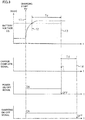
- a person on ground or a passenger on the vehicle turns on the charging start switch at a timing indicated by t1.
- a charging start signal is sent to power source side controller 14 or vehicle side controller 27.
- Power source side controller 14 and vehicle side controller 27 share the on-operation information of the charging start switch through wireless communication.
- Power source side controller 14 outputs a power on/off signal of an H level to high frequency power source 13. Specifically, power source side controller 14 outputs a power source ON command to high frequency power source 13.
- Vehicle side controller 27 outputs a charging start command to charging ECU 26.
- charging ECU 26 outputs a charging on/off signal of an H level to charger 24. In other words, charging ECU 26 outputs a charging ON command to charger 24.
- charger 24 initiates charging, whereby battery voltage Vb is boosted.
- battery voltage Vb arrives at a preset threshold value (the timing indicated by t2 in Fig. 3 )
- charging ECU 26 initiates a time count operation.
- Tc the timing indicated by t3 in Fig. 3
- charging ECU 26 determines that the charging of battery 25 is completed, and outputs a charging complete signal to vehicle side controller 27.
- vehicle side controller 27 Upon receiving a charging complete signal from charging ECU 26, vehicle side controller 27 notifies power source side controller 14 that charging has been completed through wireless communication. In response, power source side controller 14 immediately outputs a power on/off signal of an L level to high frequency power source 13. In other words, power source side controller 14 outputs a power source off command to high frequency power source 13. Accordingly, high frequency power source 13 is stopped.
- charging ECU 26 At an elapse of a predetermined delay time Td (the timing indicated by t4 in Fig. 3 ) from the elapse of predetermined charging time Tc (the timing indicated by t3 in Fig. 3 ), charging ECU 26 outputs a charging on/off signal of an L level to charger 24. In other words, charging ECU 26 outputs a charging off command to charger 24. Accordingly, charger 24 is stopped.
- power source side controller 14, vehicle side controller 27 and charging ECU 26 cooperate with each other such that charger 24 that is a device at the secondary side is stopped after high frequency power source 13 that is a device at the primary side is stopped when charging is to be stopped.
- charger 24 is stopped.
- the resonance type non-contact charging device is of the high frequency transmission scheme
- stopping charger 24 before stopping high frequency power source 13 will cause a portion of or all of the electric power transmitted from the primary side resonant coil to the secondary side resonant coil to be reflected towards the high frequency power source, leading to the possibility of high frequency power source 13 being damaged.
- the electric power reflected towards high frequency power source 13 is converted into heat, whereby high frequency power source 13 is overheated.
- charger 24 is stopped before high frequency power source 13 is stopped, the voltage at the input terminal of charger 24 will be boosted to damage charger 24.
- high frequency power source 13 that is a device at the primary side is stopped before charger 24 that is a device at the secondary side is stopped. Therefore, damage to high frequency power source 13 by reflected electric power can be prevented and the voltage at the input terminal of charger 24 will not be boosted.
- the present embodiment has the following advantages.
- the present invention is not limited to the above-described embodiment, and may be embodied as set forth below.
- vehicle side controller 27 stops high frequency power source 13 previous to stopping charger 24.
- a vehicle error signal is output when there is an error such as a breakdown, for example, when the battery is overheated, or when vehicle side controller 27 or otherwise vehicle-mounted controller is overheated.
- the resonance type non-contact charging device is applied to a hybrid vehicle
- the resonance type non-contact charging device may be applied to a vehicle other than a hybrid vehicle, as well as to a charging device used other than for a vehicle.
- Primary side resonant coil 11 and secondary side resonant coil 21 are not restricted to the form of an electric wire wound helically, and may be wound in flat spiral. In this case, the length of the coil in the axial direction is reduced, allowing a smaller depth for the hole to be formed in the ground.
- the profile of primary side resonant coil 11, primary coil 12, secondary side resonant coil 21 and secondary coil 22 is not limited to a circle, and may take, for example, a polygonal shape such as a rectangle, hexagon, triangle, or an ellipse.
- Capacitor C connected to each of primary side resonant coil 11 and secondary side resonant coil 21 is dispensable. However, a configuration with both capacitors C connected can reduce the resonant frequency, as compared to the case where capacitors C are absent. Primary side resonant coil 11 and secondary side resonant coil 21 can also be reduced in size, as compared to the case where capacitors C are absent, based on the same resonant frequency.
Landscapes
- Engineering & Computer Science (AREA)
- Power Engineering (AREA)
- Computer Networks & Wireless Communication (AREA)
- Electrochemistry (AREA)
- Chemical & Material Sciences (AREA)
- Chemical Kinetics & Catalysis (AREA)
- Manufacturing & Machinery (AREA)
- General Chemical & Material Sciences (AREA)
- Transportation (AREA)
- Mechanical Engineering (AREA)
- Charge And Discharge Circuits For Batteries Or The Like (AREA)
- Electric Propulsion And Braking For Vehicles (AREA)
- Secondary Cells (AREA)
Applications Claiming Priority (2)
| Application Number | Priority Date | Filing Date | Title |
|---|---|---|---|
| JP2008328830A JP4478729B1 (ja) | 2008-12-24 | 2008-12-24 | 共鳴型非接触充電装置 |
| EP09834904.6A EP2383858B1 (en) | 2008-12-24 | 2009-12-24 | Resonance type non-contact charging device |
Related Parent Applications (2)
| Application Number | Title | Priority Date | Filing Date |
|---|---|---|---|
| EP09834904.6A Division EP2383858B1 (en) | 2008-12-24 | 2009-12-24 | Resonance type non-contact charging device |
| EP09834904.6A Division-Into EP2383858B1 (en) | 2008-12-24 | 2009-12-24 | Resonance type non-contact charging device |
Publications (1)
| Publication Number | Publication Date |
|---|---|
| EP3312930A1 true EP3312930A1 (en) | 2018-04-25 |
Family
ID=42287712
Family Applications (2)
| Application Number | Title | Priority Date | Filing Date |
|---|---|---|---|
| EP17207402.3A Withdrawn EP3312930A1 (en) | 2008-12-24 | 2009-12-24 | Resonance type non-contact charging device |
| EP09834904.6A Active EP2383858B1 (en) | 2008-12-24 | 2009-12-24 | Resonance type non-contact charging device |
Family Applications After (1)
| Application Number | Title | Priority Date | Filing Date |
|---|---|---|---|
| EP09834904.6A Active EP2383858B1 (en) | 2008-12-24 | 2009-12-24 | Resonance type non-contact charging device |
Country Status (19)
| Country | Link |
|---|---|
| US (3) | US8212520B2 (pt) |
| EP (2) | EP3312930A1 (pt) |
| JP (1) | JP4478729B1 (pt) |
| KR (1) | KR101234126B1 (pt) |
| CN (2) | CN103633694B (pt) |
| AP (1) | AP3127A (pt) |
| AU (3) | AU2009331270B2 (pt) |
| BR (1) | BRPI0923692A2 (pt) |
| CA (1) | CA2747773C (pt) |
| CO (1) | CO6362074A2 (pt) |
| EA (1) | EA020003B1 (pt) |
| EG (1) | EG26142A (pt) |
| IL (1) | IL213704A (pt) |
| MX (1) | MX2011006565A (pt) |
| MY (1) | MY154164A (pt) |
| NZ (1) | NZ593562A (pt) |
| SG (1) | SG172418A1 (pt) |
| WO (1) | WO2010074106A1 (pt) |
| ZA (1) | ZA201104700B (pt) |
Families Citing this family (35)
| Publication number | Priority date | Publication date | Assignee | Title |
|---|---|---|---|---|
| JP4478729B1 (ja) * | 2008-12-24 | 2010-06-09 | 株式会社豊田自動織機 | 共鳴型非接触充電装置 |
| EP2375534A1 (en) * | 2010-04-09 | 2011-10-12 | Nxp B.V. | Apparatus for transferring energy to an accumulator and system for charging an electric accumulator |
| US8841881B2 (en) | 2010-06-02 | 2014-09-23 | Bryan Marc Failing | Energy transfer with vehicles |
| JP5533337B2 (ja) * | 2010-06-25 | 2014-06-25 | ソニー株式会社 | 非接触充電通信システム |
| US8917511B2 (en) | 2010-06-30 | 2014-12-23 | Panasonic Corporation | Wireless power transfer system and power transmitting/receiving device with heat dissipation structure |
| IT1400748B1 (it) * | 2010-06-30 | 2013-07-02 | St Microelectronics Srl | Apparato per il trasferimento wireless di energia fra due dispositivi e contemporaneo trasferimento di dati. |
| CN103068618B (zh) * | 2010-07-29 | 2015-06-17 | 株式会社丰田自动织机 | 谐振型非接触电力供应系统 |
| DE102010044999A1 (de) * | 2010-09-10 | 2012-03-15 | Li-Tec Battery Gmbh | Anordnung und Verfahren zum Laden einer Fahrzeugbatterie |
| JP2012118791A (ja) * | 2010-12-01 | 2012-06-21 | Oki Electric Ind Co Ltd | 取引装置、給電モジュール、及び、取引装置の電気要素への給電方法 |
| JP5561210B2 (ja) * | 2011-03-09 | 2014-07-30 | 株式会社豊田自動織機 | 非接触電力伝送装置 |
| KR101768723B1 (ko) | 2011-03-30 | 2017-08-17 | 삼성전자주식회사 | 휴대단말기의 무선 충전 방법 및 시스템 |
| JP5899490B2 (ja) * | 2011-07-20 | 2016-04-06 | パナソニックIpマネジメント株式会社 | 非接触給電システム |
| CN105966578B (zh) | 2011-12-07 | 2018-04-06 | 株式会社 Ihi | 输电装置及受电装置 |
| US9246357B2 (en) * | 2011-12-07 | 2016-01-26 | Semiconductor Energy Laboratory Co., Ltd. | Contactless power feeding system |
| JP5810944B2 (ja) * | 2012-01-31 | 2015-11-11 | トヨタ自動車株式会社 | 車両および電力伝送システム |
| JP5899306B2 (ja) * | 2012-03-14 | 2016-04-06 | パイオニア株式会社 | 非接触充電システム、非接触送電装置及び方法、並びに非接触受電装置及び方法 |
| JP6083121B2 (ja) * | 2012-03-22 | 2017-02-22 | 株式会社豊田自動織機 | 給電装置と充電装置、給電方法および給電プログラム |
| CN109067014B (zh) | 2012-09-05 | 2022-04-15 | 瑞萨电子株式会社 | 非接触充电装置 |
| DE102012023363B4 (de) * | 2012-11-29 | 2014-06-26 | Audi Ag | Hilfsrahmen für ein Kraftfahrzeug |
| WO2014169927A1 (en) * | 2013-04-15 | 2014-10-23 | Volvo Truck Corporation | Method and arrangement for error detection during charging of an energy storage system |
| EP3026787B1 (en) * | 2013-06-26 | 2018-11-28 | Nissan Motor Co., Ltd | Charging device and contactless power supply device |
| WO2014207267A1 (es) * | 2013-06-28 | 2014-12-31 | Fundación Circe - Centro De Investigacion De Recursos Y Consumos Energeticos | Sistema modular de carga inductiva para vehículos eléctricos |
| JP6249205B2 (ja) * | 2013-07-01 | 2017-12-20 | パナソニックIpマネジメント株式会社 | 給電装置及び給電装置の制御方法 |
| DE102014206739A1 (de) * | 2014-04-08 | 2015-10-08 | Bayerische Motoren Werke Aktiengesellschaft | Schubfeld für einen Vorderwagen einer Fahrzeugkarosserie eines Fahrzeugs und Fahrzeug |
| US10312746B2 (en) * | 2014-06-23 | 2019-06-04 | Htc Corporation | Power providing equipment, mobile device, operating method of mobile device |
| US10355527B2 (en) | 2014-07-16 | 2019-07-16 | Taiwan Semiconductor Manufacturing Company Limited | Wireless charging receiver with variable resonant frequency |
| CN107078555A (zh) * | 2014-10-31 | 2017-08-18 | 富士通株式会社 | 受电器、以及电力传送系统 |
| JP6350399B2 (ja) * | 2015-06-10 | 2018-07-04 | トヨタ自動車株式会社 | 非接触送電装置及び電力伝送システム |
| CN105365591A (zh) * | 2015-10-29 | 2016-03-02 | 邹斌 | 一种基于erpt技术采用无线充电的新能源汽车 |
| JP6702541B2 (ja) * | 2016-03-14 | 2020-06-03 | 株式会社東芝 | 無線電力伝送装置、送電装置および受電装置 |
| JP2018190781A (ja) | 2017-04-28 | 2018-11-29 | 小島プレス工業株式会社 | 車両用磁性部品 |
| CN110014890A (zh) * | 2017-08-02 | 2019-07-16 | 西安恒常电磁科技有限责任公司 | 一种电动自行车无线充电系统 |
| WO2019229787A1 (ja) * | 2018-05-28 | 2019-12-05 | 日産自動車株式会社 | 非接触電力伝送装置 |
| JP7061548B2 (ja) | 2018-10-04 | 2022-04-28 | 株式会社日立産機システム | 共振型電源装置 |
| JP7200908B2 (ja) * | 2019-10-30 | 2023-01-10 | トヨタ自動車株式会社 | 報知制御装置、移動体、及び電力システム |
Citations (6)
| Publication number | Priority date | Publication date | Assignee | Title |
|---|---|---|---|---|
| WO1984004212A1 (en) * | 1983-04-14 | 1984-10-25 | Towmotor Corp | Vehicle battery charging apparatus |
| JPS63287607A (ja) * | 1987-05-20 | 1988-11-24 | Mitsubishi Electric Corp | 搬送車の給電装置 |
| JPH10304582A (ja) * | 1997-04-25 | 1998-11-13 | Toyota Motor Corp | インダクティブ充電装置およびインダクティブ充電システム |
| WO2005109597A1 (en) * | 2004-05-11 | 2005-11-17 | Splashpower Limited | Controlling inductive power transfer systems |
| WO2007008646A2 (en) | 2005-07-12 | 2007-01-18 | Massachusetts Institute Of Technology | Wireless non-radiative energy transfer |
| EP2346142A1 (en) * | 2008-10-09 | 2011-07-20 | Toyota Jidosha Kabushiki Kaisha | Noncontact receiving device, and vehicle having the device |
Family Cites Families (14)
| Publication number | Priority date | Publication date | Assignee | Title |
|---|---|---|---|---|
| US4347472A (en) * | 1980-10-20 | 1982-08-31 | Lemelson Jerome H | Apparatus and method for charging a battery in a vehicle |
| JPH0739077A (ja) | 1993-07-22 | 1995-02-07 | Sony Corp | コードレスパワーステーション |
| DE69711963T2 (de) * | 1996-01-30 | 2002-11-28 | Sumitomo Wiring Systems, Ltd. | Verbindungssystem und -verfahren für ein elektrisch betriebenes Fahrzeug |
| JPH10322920A (ja) * | 1997-05-12 | 1998-12-04 | Sumitomo Wiring Syst Ltd | 電気自動車充電システムにおける異常診断方法及び電気自動車充電用コネクタ |
| JP3786392B2 (ja) * | 1998-09-09 | 2006-06-14 | 本田技研工業株式会社 | 電動車両用充電装置 |
| JP2006288034A (ja) * | 2005-03-31 | 2006-10-19 | Matsushita Electric Ind Co Ltd | 送受電装置 |
| US7825543B2 (en) | 2005-07-12 | 2010-11-02 | Massachusetts Institute Of Technology | Wireless energy transfer |
| JP2008137451A (ja) * | 2006-11-30 | 2008-06-19 | Toyota Motor Corp | 無人搬送車の自動充電方法及び装置 |
| AU2007349874B2 (en) | 2007-03-27 | 2012-02-16 | Massachusetts Institute Of Technology | Wireless energy transfer |
| JP4453741B2 (ja) * | 2007-10-25 | 2010-04-21 | トヨタ自動車株式会社 | 電動車両および車両用給電装置 |
| CN201163726Y (zh) * | 2008-01-04 | 2008-12-10 | 上海海事大学 | 非接触电能传输设备 |
| JP4478729B1 (ja) * | 2008-12-24 | 2010-06-09 | 株式会社豊田自動織機 | 共鳴型非接触充電装置 |
| JP2010183814A (ja) * | 2009-02-09 | 2010-08-19 | Toyota Industries Corp | 非接触電力伝送装置 |
| JP2012034468A (ja) * | 2010-07-29 | 2012-02-16 | Toyota Industries Corp | 車両用共鳴型非接触給電システム |
-
2008
- 2008-12-24 JP JP2008328830A patent/JP4478729B1/ja active Active
-
2009
- 2009-12-24 BR BRPI0923692A patent/BRPI0923692A2/pt not_active Application Discontinuation
- 2009-12-24 AU AU2009331270A patent/AU2009331270B2/en not_active Ceased
- 2009-12-24 KR KR1020117015707A patent/KR101234126B1/ko not_active Expired - Fee Related
- 2009-12-24 MY MYPI2011002961A patent/MY154164A/en unknown
- 2009-12-24 AP AP2011005781A patent/AP3127A/xx active
- 2009-12-24 MX MX2011006565A patent/MX2011006565A/es active IP Right Grant
- 2009-12-24 EA EA201100825A patent/EA020003B1/ru not_active IP Right Cessation
- 2009-12-24 CN CN201310584936.9A patent/CN103633694B/zh not_active Expired - Fee Related
- 2009-12-24 EP EP17207402.3A patent/EP3312930A1/en not_active Withdrawn
- 2009-12-24 US US13/132,240 patent/US8212520B2/en not_active Expired - Fee Related
- 2009-12-24 EP EP09834904.6A patent/EP2383858B1/en active Active
- 2009-12-24 NZ NZ593562A patent/NZ593562A/xx not_active IP Right Cessation
- 2009-12-24 CA CA2747773A patent/CA2747773C/en active Active
- 2009-12-24 CN CN200980152299XA patent/CN102265479B/zh not_active Expired - Fee Related
- 2009-12-24 WO PCT/JP2009/071371 patent/WO2010074106A1/ja not_active Ceased
- 2009-12-24 SG SG2011047396A patent/SG172418A1/en unknown
-
2011
- 2011-06-21 EG EG2011061057A patent/EG26142A/en active
- 2011-06-21 IL IL213704A patent/IL213704A/en not_active IP Right Cessation
- 2011-06-24 ZA ZA2011/04700A patent/ZA201104700B/en unknown
- 2011-06-24 CO CO11079788A patent/CO6362074A2/es active IP Right Grant
-
2012
- 2012-06-05 AU AU2012203307A patent/AU2012203307B2/en not_active Ceased
- 2012-06-05 AU AU2012203309A patent/AU2012203309B2/en not_active Ceased
- 2012-06-08 US US13/492,372 patent/US8421411B2/en not_active Expired - Fee Related
- 2012-06-08 US US13/492,317 patent/US8421410B2/en not_active Expired - Fee Related
Patent Citations (6)
| Publication number | Priority date | Publication date | Assignee | Title |
|---|---|---|---|---|
| WO1984004212A1 (en) * | 1983-04-14 | 1984-10-25 | Towmotor Corp | Vehicle battery charging apparatus |
| JPS63287607A (ja) * | 1987-05-20 | 1988-11-24 | Mitsubishi Electric Corp | 搬送車の給電装置 |
| JPH10304582A (ja) * | 1997-04-25 | 1998-11-13 | Toyota Motor Corp | インダクティブ充電装置およびインダクティブ充電システム |
| WO2005109597A1 (en) * | 2004-05-11 | 2005-11-17 | Splashpower Limited | Controlling inductive power transfer systems |
| WO2007008646A2 (en) | 2005-07-12 | 2007-01-18 | Massachusetts Institute Of Technology | Wireless non-radiative energy transfer |
| EP2346142A1 (en) * | 2008-10-09 | 2011-07-20 | Toyota Jidosha Kabushiki Kaisha | Noncontact receiving device, and vehicle having the device |
Also Published As
Similar Documents
| Publication | Publication Date | Title |
|---|---|---|
| EP2383858B1 (en) | Resonance type non-contact charging device | |
| JP5285418B2 (ja) | 共鳴型非接触電力供給装置 | |
| JP5459058B2 (ja) | 共鳴型非接触電力伝送装置 | |
| EP2571140B1 (en) | Resonance-type non-contact power supply system, and adjustment method for matching unit during charging of resonance-type non-contact power supply system | |
| JP5282068B2 (ja) | 共鳴型非接触給電システムの受電側設備 | |
| JP5307073B2 (ja) | 非接触受電システム及び非接触電力伝送システム | |
| US10052963B2 (en) | Contactless power transfer system and method of controlling the same | |
| CN104821636B (zh) | 非接触电力传输系统 | |
| CN103068618B (zh) | 谐振型非接触电力供应系统 | |
| EP3057113A1 (en) | Contactless power transmission device |
Legal Events
| Date | Code | Title | Description |
|---|---|---|---|
| PUAI | Public reference made under article 153(3) epc to a published international application that has entered the european phase |
Free format text: ORIGINAL CODE: 0009012 |
|
| STAA | Information on the status of an ep patent application or granted ep patent |
Free format text: STATUS: REQUEST FOR EXAMINATION WAS MADE |
|
| 17P | Request for examination filed |
Effective date: 20171214 |
|
| AC | Divisional application: reference to earlier application |
Ref document number: 2383858 Country of ref document: EP Kind code of ref document: P |
|
| AK | Designated contracting states |
Kind code of ref document: A1 Designated state(s): AT BE BG CH CY CZ DE DK EE ES FI FR GB GR HR HU IE IS IT LI LT LU LV MC MK MT NL NO PL PT RO SE SI SK SM TR |
|
| AX | Request for extension of the european patent |
Extension state: AL RS |
|
| RAP1 | Party data changed (applicant data changed or rights of an application transferred) |
Owner name: TOYOTA JIDOSHA KABUSHIKI KAISHA |
|
| STAA | Information on the status of an ep patent application or granted ep patent |
Free format text: STATUS: EXAMINATION IS IN PROGRESS |
|
| RBV | Designated contracting states (corrected) |
Designated state(s): AT BE BG CH CY CZ DE DK EE ES FI FR GB GR HR HU IE IS IT LI LT LU LV MC MK MT NL NO PL PT RO SE SI SK SM TR |
|
| RAX | Requested extension states of the european patent have changed |
Extension state: RS Payment date: 20181025 Extension state: AL Payment date: 20181025 |
|
| 17Q | First examination report despatched |
Effective date: 20181109 |
|
| DAX | Request for extension of the european patent (deleted) | ||
| STAA | Information on the status of an ep patent application or granted ep patent |
Free format text: STATUS: THE APPLICATION HAS BEEN WITHDRAWN |
|
| 18W | Application withdrawn |
Effective date: 20190315 |