EP3339652A1 - Pompe à vide avec chemise intérieure recueillant des dépôts - Google Patents
Pompe à vide avec chemise intérieure recueillant des dépôts Download PDFInfo
- Publication number
- EP3339652A1 EP3339652A1 EP16206042.0A EP16206042A EP3339652A1 EP 3339652 A1 EP3339652 A1 EP 3339652A1 EP 16206042 A EP16206042 A EP 16206042A EP 3339652 A1 EP3339652 A1 EP 3339652A1
- Authority
- EP
- European Patent Office
- Prior art keywords
- insert
- chamber
- vacuum pump
- pump according
- outlet
- Prior art date
- Legal status (The legal status is an assumption and is not a legal conclusion. Google has not performed a legal analysis and makes no representation as to the accuracy of the status listed.)
- Granted
Links
Images



Classifications
-
- F—MECHANICAL ENGINEERING; LIGHTING; HEATING; WEAPONS; BLASTING
- F04—POSITIVE - DISPLACEMENT MACHINES FOR LIQUIDS; PUMPS FOR LIQUIDS OR ELASTIC FLUIDS
- F04D—NON-POSITIVE-DISPLACEMENT PUMPS
- F04D29/00—Details, component parts, or accessories
- F04D29/70—Suction grids; Strainers; Dust separation; Cleaning
- F04D29/701—Suction grids; Strainers; Dust separation; Cleaning especially adapted for elastic fluid pumps
-
- F—MECHANICAL ENGINEERING; LIGHTING; HEATING; WEAPONS; BLASTING
- F04—POSITIVE - DISPLACEMENT MACHINES FOR LIQUIDS; PUMPS FOR LIQUIDS OR ELASTIC FLUIDS
- F04D—NON-POSITIVE-DISPLACEMENT PUMPS
- F04D19/00—Axial-flow pumps
- F04D19/02—Multi-stage pumps
- F04D19/04—Multi-stage pumps specially adapted to the production of a high vacuum, e.g. molecular pumps
-
- F—MECHANICAL ENGINEERING; LIGHTING; HEATING; WEAPONS; BLASTING
- F04—POSITIVE - DISPLACEMENT MACHINES FOR LIQUIDS; PUMPS FOR LIQUIDS OR ELASTIC FLUIDS
- F04D—NON-POSITIVE-DISPLACEMENT PUMPS
- F04D29/00—Details, component parts, or accessories
- F04D29/40—Casings; Connections of working fluid
- F04D29/403—Casings; Connections of working fluid especially adapted for elastic fluid pumps
-
- F—MECHANICAL ENGINEERING; LIGHTING; HEATING; WEAPONS; BLASTING
- F05—INDEXING SCHEMES RELATING TO ENGINES OR PUMPS IN VARIOUS SUBCLASSES OF CLASSES F01-F04
- F05D—INDEXING SCHEME FOR ASPECTS RELATING TO NON-POSITIVE-DISPLACEMENT MACHINES OR ENGINES, GAS-TURBINES OR JET-PROPULSION PLANTS
- F05D2260/00—Function
- F05D2260/60—Fluid transfer
- F05D2260/607—Preventing clogging or obstruction of flow paths by dirt, dust, or foreign particles
Definitions
- the present invention relates to a vacuum pump, in particular turbomolecular pump, comprising a housing with at least one inlet for fluid, in particular process gas or air, to which a recipient is connectable, and with at least one outlet for the fluid, and at least one pumping stage arranged in the housing Conveying the fluid, in particular from the recipient, through the vacuum pump from the inlet to the outlet, wherein a chamber, in particular opening into the outlet and preferably forming an ejection region of the vacuum pump, is formed in the housing.
- Vacuum pumps such as turbomolecular pumps, are used in various fields of technology to create a vacuum necessary for a particular process.
- deposits such as process impurities, particles and / or liquid residues, accumulate or deposit from the fluid pumped by the pump in the vacuum pump and primarily there in the fore-vacuum region.
- deposits possibly also corrosive and toxic deposits must be removed during maintenance with some great effort, in particular by mechanical, physical and / or chemical cleaning.
- the present invention has the object to provide a vacuum pump that can be easily cleaned.
- deposits should be easy to remove from the fore-vacuum region of the vacuum pump.
- a vacuum pump according to the invention in particular turbomolecular pump, comprises a housing with at least one inlet and one outlet for fluid, in particular process gas or air, wherein a recipient can be connected to the inlet.
- the vacuum pump according to the invention further comprises at least one pumping stage arranged in the housing for conveying the fluid, in particular from the recipient, through the vacuum pump from the inlet to the outlet, wherein a chamber is further formed in the housing, and wherein at least one insert for receiving is arranged by deposits, which covers at least one side bounding the chamber.
- the chamber preferably opens into the outlet and preferably forms an ejection region of the vacuum pump.
- the chamber is therefore preferably in the fore-vacuum region of the pump.
- the chamber is preferably arranged in the pumping direction downstream of the pumping stage closest to the vacuum in the housing.
- the pump passage through the vacuum pump, through which the fluid flows in the pump, extends through the chamber.
- the sucked by the pump, deposits contained in the fluid can therefore deposit on the deposit.
- the insert may preferably be arranged in the chamber such that it can be removed from the chamber, for example as part of a maintenance of the pump.
- the removed insert can cleaned outside the pump and then re-used in the pump.
- the soiled liner can be replaced with a new liner.
- the cost of cleaning the chamber from the deposits can be reduced by using the insert or save completely in the optimal case. This can also reduce the risk of damaging sensitive assemblies in the fore-vacuum range.
- deposit is to be understood broadly and may include any type of material such as particles, liquids, gases or exotic states such as plasma or atomic gas contained in the fluid pumped by the vacuum pump and may be approximately in the vacuum pump can "settle” by adhesion, condensation, resublimation, solidification or chemical reaction.
- the insert In the chamber bounding the side, which at least partially covers the insert, it may be a lateral wall and / or the bottom of the chamber.
- the insert can be designed such that it covers the largest possible surface of the chamber or the chamber walls. As many deposits as possible can deposit on the insert and not on the chamber surfaces.
- the insert can be designed shell-like, box-like or container-like.
- the insert can therefore have or define an externally accessible volume in which the deposits can deposit and accumulate.
- the insert may be designed such that it covers the bottom of the chamber and / or a side wall bounding the chamber radially outwardly and / or a side wall defining the chamber radially inward, in particular at least substantially completely.
- the insert surrounds, in particular its bottom and side walls, a volume, wherein at least one side of the insert, in particular at the top of the insert, at least one opening is provided, so that the deposits can be absorbed through the opening in the volume.
- the opening can be designed so that the insert has no wall on the corresponding side.
- the opening may alternatively be designed so that one or more openings, such as slots, are provided in a wall.
- the insert can thus be completely or at least partially opened on its upper side remote from the bottom, so that the deposits can accumulate from above in the volume.
- the insert is formed and / or may be mounted in the chamber such that the at least one opening faces the pumping step upstream of the chamber.
- Deposits sucked in by the pumping stage and conveyed towards the outlet can thus reach directly into the volume of the insert and be accumulated there. A possible contamination of the chamber walls by deposits can thus be further reduced.
- the insert is preferably designed as a shell whose shape is adapted in particular to the shape of the chamber. Due to the shell shape process impurities, deposits and other substances or particles can be collected very well and stored in the volume defined by the shell.
- the shell is preferably at least partially open on one side, in particular on the side which is directed in the intended installation position in the direction of the upstream pumping stage. The deposits can thus be accumulated particularly well in the volume formed by the shell.
- the chamber may, in particular below the pumping stage, ring around a central axis of the vacuum pump, in particular about an axis of rotation of a
- the chamber can thus form a kind of annular space under the pumping stage, which has a favorable effect on, among other things, the pumping stage's pumping speed.
- the chamber preferably has an at least approximately rectangular cross-section. This cross-sectional shape can be particularly easily realized manufacturing technology.
- the insert can be designed as a corresponding to the chamber, at its upper side at least partially open, preferably annular, shell with a bottom and, preferably vertically to the ground, in particular upwardly extending, radially inside or radially outer side walls.
- the insert can thus, in particular fitting, insert in the annularly shaped chamber.
- the shell, as well as the chamber have an at least approximately rectangular cross-section.
- the insert can be fixed and / or fixable in the chamber by means of at least one fixation.
- the fixation may comprise, for example, at least one screw by means of which the insert is fastened to the chamber or to an inner wall of the housing.
- the screw can be screwed or screwed, for example, from above into the bottom of the insert and the underlying chamber floor.
- a screw with a large head such as a pan head screw or hexagon screw, is used, since such a screw can be easily located and loosened with tools in a floor covered with deposits.
- the insert can also be designed and / or dimensioned such that it can be fixed in a clamping arrangement with the stator assembly of the pumping stage located above the chamber in the chamber. That is, the mentioned stator can be used as a kind of fixation for the insert.
- the insert can, in particular by pressing on the insert, be brought from a first mold into a second mold, wherein the insert in the second mold has a larger outer diameter and / or a smaller inner diameter compared to the first mold, and / or wherein the insert has in the second form with respect to the first form plastic and / or elastic shape changes.
- the insert can thus be placed in the first shape in the chamber and, in particular by pressing on the insert or by inserting the insert into the chamber, this can be brought into the second shape, whereby the outer diameter and / or the inner diameter of the Insole changes at least slightly, or resulting in plastic and / or elastic changes in shape of the insert.
- the change in shape allows the insert to be "clamped" into the chamber, as it were, so that the insert can be fixed in the chamber.
- the change in shape of the insert can be reversible. To remove or after removing the insert this can thus be brought back into the first form.
- the change in shape can be made possible in that at least one side of the insert, in particular the radially outer side wall of the insert is configured so that, for example by pressing on the insert, the dimensioning of the side, in particular its radial extent is adjustable.
- the change in shape can also be made possible in that at least one side of the insert, in particular the radially outer side wall of the insert is configured so that, for example by pressing on the insert, the dimensioning of the side, in particular its axial extent, is adjustable.
- the side wall consists of at least two sub-areas, which are connected by at least one circumferential deformation region with deformation elements and recesses, in particular in the axial direction are and is configured such that by pressing the insert at least one deformation element is elastically or plastically deformed, wherein at least one recess is reduced and the axial extent of the side wall is thus also reduced.
- the insert in particular by pressing on the insert, can be brought from a first shape into a second shape, in which the insert, in particular the radially outer side wall, has a greater or smaller axial height relative to the first form ,
- the axial extent of the insert can thus be adjustable.
- At least one seal is arranged between an outer side of the insert and a side wall of the chamber.
- the lying behind the outside of the liner chamber wall can be effectively protected from deposits.
- the seal can also cause an entrapment of the insert in the chamber and thus act as a fixation.
- the seal which is preferably inserted between the upper edge of the insert and the underlying side wall of the chamber, can also act as a kind of pressure distributor and possibly distribute existing tolerances or forces, in particular axial tolerances or forces, so that on the one hand the insert firmly is fixed in the chamber and on the other hand, a chamber upstream of the stator is securely clamped.
- the insert may have an outlet opening that can be aligned, in particular, with the outlet on the housing of the vacuum pump.
- the fluid can thus pass through the volume of the insert into the outlet opening of the insert and further into the outlet of the vacuum pump.
- the outlet opening may have a diameter which corresponds at least substantially to the diameter of the outlet of the vacuum pump.
- the outlet opening may be removed, for example, by removal, in particular cut, be formed by material from the insert.
- the outlet of the vacuum pump can have a forevacuum nozzle, into which the chamber opens, and the insert can have an orifice portion, which can be introduced or introduced into the fore-vacuum nozzle.
- the mouth portion may at least partially cover the inner wall of the forevacuum nozzle and thus protect it from deposits.
- the mouth portion is preferably formed by the portion of the liner material which has been cut away from the liner to provide the outlet opening, wherein the mouth portion is preferably integrally connected to the liner. There is thus no additional material needed for the mouth section. Rather, only the material of the insert is used, which has been "vacated” by creating the outlet opening.
- the mouth portion may be formed as a separate part of the particular shell-like insert.
- the mouth portion can be inserted into the Vorvakuumstutzen.
- the mouth portion may be formed to match the Vorvakuumstutzen.
- the outer diameter of the mouth portion may thus correspond substantially to the inner diameter of the forevacuum nozzle.
- the axial length of the mouth portion may be adapted to the axial length of the forevacuum neck. The inserted into the Vorvakuumstutzen, matching mouth section can thus protect the Vorvakuumstutzen effectively against deposits.
- the insert may be made of metal, in particular as a sheet or foil, or of a, preferably inert, plastic, such as PTFE.
- PTFE stands for polytetrafluoroethylene.
- the insert may comprise at least one coating, in particular an anti-adhesion layer, e.g. with nickel or PTFE, and / or a film-like layer.
- the surfaces of the insert can be protected, for example, from aggressive deposits.
- the coating may be such that it can be removed by means of a cleaning agent, in particular with the deposits, and in particular flushed out of the chamber.
- the insert may be formed by spraying or applying at least one layer of a spray foil or the like on the sides of the chamber to be covered.
- the layer can be pulled off the chamber walls, in particular with the deposits accumulated thereon.
- the layer may be such that it can be removed by means of a cleaning agent, in particular with the deposits, and in particular flushed out of the chamber. By re-spraying or applying a new layer can then be formed.
- the insert may be formed one or more parts.
- a backing pump e.g. a rotary vane pump to be connected.
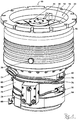
- Vacuum pump 10 shown comprises a housing 16 with a pump inlet 14 surrounded by an inlet flange 12, in the housing 16 a plurality of pumping stages for conveying the pending at the pump inlet 14 gas to a provided at the lower part 90 of the housing pump outlet 74. Between the lower part 90 and the housing 16 is a Seal 81 arranged.
- the vacuum pump 10 comprises in the housing 16 or in the lower part 90 a stator and a rotor with a rotor shaft 20 rotatably mounted about a rotation axis 18.
- the vacuum pump 10 is designed as a turbomolecular pump and comprises a plurality of pump-connected with each other in series turbomolecular pumping stages with a plurality of connected to the rotor shaft 20 turbomolecular rotor disks 22 and a plurality of axially disposed between the rotor disks 22 and fixed in the housing 16 turbomolecular stator disks 24 by spacer rings 26 are held at a desired axial distance from each other.
- the pump-active system realized by means of the turbomolecular pumping stages therefore builds up in regular alternation of rotor disks 22 and stator disks 24. Only a few of the components shown were marked with numbers for readability.
- the rotor disks 22 and stator disks 24 provide in a scooping region 28 an axial pumping action directed in the direction of the arrow 30.
- the vacuum pump 10 may optionally have subordinate to the turbomolecular pumping stages one or more, known per se Holweck pumping stages, which are not shown.
- three Holweck pumping stages which are arranged one inside the other in the radial direction and pump-connected with one another in series, may be provided.
- the rotor-side part of the Holweck pumping stages can have a rotor hub connected to the rotor shaft 20 and two cylinder cover-shaped Holweck rotor sleeves fastened to the rotor hub and supported by the latter, which are oriented coaxially with the rotor axis 18 and radially Direction are nested in each other.
- Holweck stator sleeves can be provided, which are also oriented coaxially with the axis of rotation 18 and are nested in the radial direction.
- the pump-active surfaces of the Holweck pump stages are each formed by the radial lateral surfaces of a Holweck rotor sleeve and a Holweck stator sleeve opposite one another, forming a narrow radial Holweck gap.
- one of the pump-active surfaces is smooth, in particular that of the Holweck rotor sleeve, and the opposite pump-active surface, in particular the Holweck stator, has a structuring with helically around the rotation axis 18 in the axial direction extending grooves in which through the Rotation of the rotor propelled the gas and thereby pumped.
- the Holweck pump stages are not provided.
- a sealing region 34 is formed by a specially, in this case asymmetrically shaped, stator disk 24 which minimizes the remaining gaps to the rotor disks 22 to provide better sealing against unwanted backflow between the first and second pumping stages.
- a biasing and sealing ring 32 is disposed between the inner wall of the housing 16 and the turbomolecular pumping stages, in particular between two spacer rings 26.
- the biasing and sealing ring 32 ensures that the tolerance-laden stack of spacer rings 26 is securely biased axially between the housing 16 and lower part 90. Furthermore, it additionally seals the gap between the stack of spacer rings 26 and the wall of the housing 16 against undesired backflow from the fore-vacuum / ejection area into the high-vacuum / intake area.
- a flood gas inlet 36 is arranged, via which the vacuum pump 10 can be flooded with flooding gas.
- the flood gas inlet 36 is advantageous Downstream of the terminal and the sealing ring 32.
- the height of the terminal lying spacer ring 26 is preferably provided on its lateral surface over the entire circumference with a channel or a recess, so that the flooding gas first in the entire annular channel with good Distributed conductance and then as uniformly as possible penetrates the gap or the recesses in the stator stack with a lower conductance over the circumference and reaches the mechanically more stable upstream prevacuum pump stages against flooding.
- a coolant inlet 38 and a coolant outlet 40 are arranged, between which runs a coolant line formed by at least one coolant tube 76, which is guided in turns around the lower part 90.
- a coolant pump can be connected, by means of which cooling liquid can be pumped through the coolant line in order to cool the vacuum pump 10.
- the coolant tube 76 may be in preformed recesses of the lower part 90, for example according to EP 3 070 335 A1 be pressed in.
- the pipe ends can either protrude out of the contour of the pump 10 as a respective pipe section at an arbitrary angle, in order to be connected to the inlet 38 or outlet 40, for example with insulation displacement screw connections or special connectors.
- connection blocks which form the inlet 38 and the outlet 40 and which in turn are fixed to the lower part 90.
- the tight connection of tube 76 and terminal block 38, 40 can be produced in various ways, for example by soldering, welding, clamping / pressing / stretching or with separate sealing elements, such as (cutting) sealing rings or bands or with special connectors with integrated sealing system.
- a coolant line which has three complete, spirally arranged wraps of the lower part 90 starting from the inlet 38 and then ends at the outlet 40.
- any number or portion of wraps may intersect one or more times at different radius and / or at different axial heights of the axis of rotation 18, or may also be reversed one or more times in its direction of rotation, e.g. by means of U-shaped bends or arranged Umlenkblöcken that receive two pipe pieces ends similar to the terminal blocks and establish a connection between them.
- Such connection and diverter blocks may also include a valve that controls the flow of coolant or may interrupt it as needed.
- any block may also have another terminal to which e.g. an additional, in particular parallel, coolant line or one or more valves for a deflection or distribution of the coolant flow as needed in different branches of the coolant pipe system, which can also serve as a bypass or diversion is present or are available.
- the rotatable mounting of the rotor shaft 20 is effected by a rolling bearing 42 in the region of the pump outlet 74 and a permanent magnet bearing 44 in the region of the pump inlet 14.
- the permanent magnet bearing 44 comprises a rotor-side bearing half 46 and a stator bearing half 48, each comprising a ring stack of a plurality of stacked in the axial direction of permanent magnetic rings 50, 52, wherein the magnetic rings 50, 52 facing each other with formation of a radial bearing gap 54.
- an emergency or catch bearing 56 is provided, which is designed as an unlubricated roller bearing and runs empty during normal operation of the vacuum pump without touching and only with an excessive radial deflection of the rotor with respect to the stator engages to a form a radial stop for the rotor, which prevents a collision of the rotor-side structures with the stator-side structures.
- the emergency or safety bearing 56 is taken separately via an insert and can therefore be changed independently of the permanent magnet bearing 44.
- the rolling bearing 42 is gripped by a ring holder, which in turn is axially and radially decoupled by elastomeric elements in a rolling bearing support or rolling bearing mount 84 is received, which is securely fixed to the lower part 90.
- Mechanical stops limit the possible relative movements between the ring holder and the roller bearing suspension 84.
- a conical spray screw 58 with an outer diameter which increases towards the rolling bearing 42 is provided on the rotor shaft 20, which can receive operating means, in particular lubricants, supplied by means of a lubricant channel 60 and feed it to the rolling bearing.
- the propeller screw 58 may preferably according to EP 2 740 956 A2 be designed.
- the resource is circulated by a lubricant pump 78.
- the lubricant pump 78 is preferably according to EP 2 060 794 A2 built up. In particular, it can supply a lubricant supply channel which, at least in a segment according to EP 2 801 725 A2 constructed as an O-ring sealed round channel.
- the vacuum pump 10 includes a drive motor 62 for rotatably driving the rotor whose rotor is formed by the rotor shaft 20.
- a control unit 64 controls the drive motor 62. Via an electrical connection 66, the vacuum pump 10 and in particular the control unit 64 and the drive motor 62 are supplied with electric power.
- the control unit 64 forms the lower portion of the housing and is closed by the lid 80.
- one or more seals 77 may be inserted circumferentially between control unit 64, cover 80 and / or lower part 90, or the corresponding transitions with other sealing means, such as liquid sealants, adhesives or especially moldable seals be closed in order to obtain security against the ingress of media and / or impurities.
- the current can be conducted through the cover 80 into the housing and, in particular, supplied to the drive motor 62.
- the vacuum feedthrough 86 can according to EP 1 843 043 A2 be configured, in the example described here, a board with multiple sealing rings separately different voltage potentials and signals from each other separately from the pump interior, ie from the vacuum area, outwards, so the "atmosphere" and in particular to the control unit 64 leads.
- both the control unit 64 or on the part of the drive motor 62 or on the part of the pump-active components on the housing 16 mainly undesirable heat into the pump can be introduced.
- the coolant such as water, advantageously flows from the inlet 38 to the outlet 40 because the control unit 64 is to be kept coolest.
- a cover 88 may be arranged on the radial outer side of the lower part 90.
- the casing 88 which can be designed as a shell-shaped longitudinally to the axis of rotation 18 of the pump 10 slotted sheet metal sleeve, is advantageously not shown in the external view of the pump 10 in order to obtain a better view of the underlying solutions.
- the trim 88 may include one or more viewing windows or cutouts around any ports of the base 90, for example, a sealing gas inlet 68 to perform to the outside or to share the view of the type data (nameplate or engraving) of the pump 10, which are permanently attached to the lower part.
- the barrier gas inlet 68 is also referred to as flushing gas connection.
- Purge gas may be introduced via the purge gas inlet 68 to protect the engine 62 in the engine compartment in which the engine 62 is housed.
- the gas introduced via the blocking gas inlet 68 in the region of the engine protects the components located in the lower part 90 from corrosive and / or self-depositing media, which can occur in the pumping system depending on the application.
- a seal 83 is arranged, so that a labyrinth seal 72 as the only remaining passage on the one hand with their low conductance is a barrier against inflowing media in the engine and rolling bearing area and continue to increase saturation of Wälzlager- and engine area with lock - / inert gas ensures.
- the labyrinth seal 72 is provided between an engine compartment 82 which delimits the engine compartment at the top and the lower rotor disk 22.
- the electric drive motor 62 is advantageously protected by a potting compound against corrosion.
- the motor support 82 is integrally molded integrally with the drive motor, so that the entire unit including the integrally formed with the motor mount stator side of the labyrinth seal 72 can be optimally aligned or centered in one step with the lower part 90.
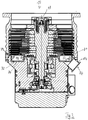
- the fore-vacuum region Radially outside the labyrinth seal 72 and below the turbomolecular pumping stages is the fore-vacuum region, in which, in particular, a chamber 70, which runs around the rotational axis 18 in a ring-shaped fashion, which, as in FIG Fig. 2 and 3 can be seen, has a substantially rectangular cross section.
- this cross-sectional shape is only an example. so that also a different cross-sectional shape, for example a square or circular cross section, can be realized.
- the chamber 70 can also be accommodated at a different location in the housing 16 or in the lower part 90.
- the chamber 70 is where most of the deposits occur, typically in the fore-vacuum region.
- the chamber 70 is thus located between the last pumping stage and the pump outlet 74.
- the chamber 70 opens into the pump outlet 74.
- the chamber 70 therefore forms a Austoss Scheme for funded by the vacuum pump 10 from the inlet 14 ago gas, which can pass through the pump outlet 74 in a connected thereto backing pump (not shown).
- the fore-vacuum pump can then further convey the gas, for example into a line for exhaust gas which is under normal pressure.
- the sectional view of Fig. 3 corresponds to the sectional view of Fig. 2 , It is according to Fig. 3 arranged in the chamber 70, an insert 92 on which settle or accumulate deposits that pass through the sucked by the pump 10 gas in the pump 10 and experience, mainly in the chamber 70 deposit.
- the deposits such as substances, particles and / or liquid drops, do not deposit directly on the covered or covered by the insert 92 walls of the chamber 70, but on the liner 92.
- the liner 92 may, for example, in a maintenance of the pump 10 taken out of the chamber 70 and cleaned or replaced by a new liner 92. The deposits can therefore be easily removed from the pump 10.
- the insert 92 is formed substantially matching the shape of the chamber 70.
- the insert 92 can thus be suitably inserted into the chamber 70.
- the insert 92 can then lie directly in front of the chamber walls to be covered.
- the liner 92 like the chamber 70, a circular ring shape with a seen in the radial direction substantially rectangular cross-section.
- the insert 92 is preferably formed from sheet metal. However, it can also be made of a different material, such as plastic, in particular PTFE.
- the liner 92 includes a bottom 94, a radially inner side wall 96, and a radially outer side wall 98 that extend approximately or entirely vertically upwardly from the bottom 94. If, for example, the insert 92 is produced at least partly in the form of a casting, one or more elements can advantageously have draft angles.
- the bottom 94 and sidewalls 96, 98 enclose a top open volume 100.
- the insert 92 therefore has the shape of an annular shell or, more generally, the shape of an annular container.
- the upstream pump stage facing side open.
- gas ejected from the pumping stage can enter the volume 100 without being blocked by a wall or the like, so that deposits can accumulate particularly well in the volume 100.
- the insert 92 also has an outlet opening 102 (cf. 4 and 5 ), whose cross section preferably corresponds to the cross section of the pump outlet 74.
- the insert 92 is thereby arranged in the chamber 70, that the outlet opening 102 is aligned with the pump outlet 74.
- the gas can thus flow through the outlet opening 102 into the pump outlet 74 and thus out of the pump 10.
- the outlet opening 102 can be created by cutting it out of the insert 92 or otherwise separating it out.
- the insert 92 is fixed in the chamber 70, preferably by means of at least one fixation.
- the insert 92 can be fixed, for example, in a clamping connection with the package of the stator disks 24.
- the radially outer side wall 98 can extend so far up that its upper end abuts against the bottom stator 24.
- the insert 92 can therefore be fixed in the chamber 70 by means of the lowermost stator disk 24.
- the upper end of the radially inner side wall 96 may be directed radially inward.
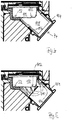
- Fig. 4 shows a section of the sectional view of Fig. 3 in which a part of a variant of the insert 92 can be seen in cross-section.
- the part of the insert 92 is located in the region of the pump outlet 74 and has the above-mentioned outlet opening 102.
- a mouth portion 106 extends in the pump outlet 74 having Vorvakuumstutzen 104 of the pump 10.
- the mouth portion 106 may be designed as a separate part, in particular as a tubular member having an outer diameter substantially equal to the inner diameter of the Vorvakuumstutzens 104.
- the mouth portion 106 may be inserted into the forevacuum neck 104.
- the channel 108 formed by the mouth section 106 can thereby connect to the outlet opening 102 of the insert 92.
- the mouth portion 106 may also be formed integrally with the insert 92.
- Fig. 5 shows a section of the sectional view of Fig. 3 in which in turn the part of the insert 92 can be seen in cross section, which is located in the region of the pump outlet 74 and has the outlet opening 102.
- the insert 92 shown is a modified variant in which the mouth portion 106 is formed by the material that is obtained through the cutout of the outlet opening 102.
- the mouth portion 106 may be formed by triangular shaped pieces of material 110 formed by a kind of star-shaped opening or cutting of the outlet opening 102, respectively.
- the pieces of material 110 remain connected to the insert 92.
- the pieces of material 110 can be pressed into the forevacuum nozzle 104 and in particular brought into contact with the inner wall of the forevacuum nozzle 104.
- the covered inner wall portions of the nozzle 104 are thus protected from deposits.
- Fig. 6 shows a section of the sectional view of Fig. 3 in which a part of yet another variant of the insert 92 can be seen in cross-section.
- a screw 112 may be threaded into a bore in the bottom 94 of the insert 92 and into an underlying bore in the bottom of the chamber 70 to fix the insert 92.
- the screw 112 is, as shown, preferably a cheese-head screw, so that it is easy to find when the bottom 94 is covered with deposits.
- In the direction of rotation of the axis of rotation 18 (see. Fig. 3 ) Can be offset from each other several screws 112 for fixing the insert 92 in the bottom 94 of the insert 92 and be screwed into the chamber floor.
- Fig. 7 shows a section of the sectional view of Fig. 3 in which a part of yet another variant of the insert 92 can be seen in cross section, in comparison to the variant of Fig. 6 has no screw 112 for fixing.
- the insert 92 is again open at its upper side 114.
- AIlerdings are in the side wall 98 along the circumferential direction of the side wall 98 offset from each other, elongated, continuous openings 116, in particular slots or openings provided.
- the openings 116 are preferably as in FIG Fig. 7 is shown, arranged in the region of the upper edge of the side wall 98.
- the upper edge of the side wall 98 has a wavy structure due to the openings 116.
- the insert 92 can be brought from a first shape into a second shape, in particular by pressing on the side wall 98 from above, wherein the insert 92 in the second shape is reduced or compressed seen in the axial direction.
- the upper edge of the side wall 98 with the openings 116 thereby forms a circumferential deformation region.
- the openings 116 can be plastically or elastically deformed and reduced, so that the axial extent of the side wall 98 is reduced and the insert 92 is thus compressed in the axial direction.
- the openings 114 therefore allow axial deflection of the side wall 98 to vary the overall height.
- the insert 92 can behave like a kind of coil spring and thus be clamped between the bottom stator 24 and the bottom of the chamber.
- the insert 92 can also be designed so that at least slightly the outer side wall 98 can be moved radially outward and / or the inner side wall 96 radially inward by "impressing" the insert 92, so that they are in contact with the inner or outside chamber wall arrives.
- the insert 92 can thereby also be fixed or clamped in the chamber 70. This can be made possible, for example, by the fact that the side wall 98 has a plurality of circumferentially offset, continuous openings 116, which extend from the upper edge of the side wall at least substantially in the axial direction downwards (not shown).
- the side wall 98 thereby has several circumferentially offset at its upper edge mutually lying tabs that can tilt, for example, radially outward to clamp the insert 98 in the chamber 70.
- Fig. 7 also shows, in the radially outer wall of the chamber 70 in the circumferential direction of the side wall 98 and in the direction of rotation of the rotation axis 18 (see. Fig. 3 ) circumferential groove 118 may be formed.
- the radially outwardly directed upper end of the side wall 98 engage, whereby the fixation of the insert 92 in the chamber 70 can be further improved.
- the groove 118 preferably runs directly below the lowermost stator disk 24.
- the radially outer side wall 98 also has a slightly bent, raised edge, which abuts axially on the first and lowermost stator disk 24 and is under axial pressure.
- Fig. 8 shows a section of the sectional view of Fig. 3 in which a part of a variant of the insert 92 can be seen in cross-section.
- a circumferential around the axis of rotation 18 seal 120 is arranged between the radially outer side wall 98 of the insert 92 and the outer wall of the chamber 70.
- the seal 120 is preferably inserted into a circumferential groove 118, which is introduced into the outer side wall 98.
- a circumferential around the axis of rotation 18 seal 122 is inserted.
- the seals 120 and 122 act as a type of pressure manifold and cause the liner 92 to be fixed in the chamber 70. In addition, they provide a sealing action between the respective side wall 96, 98 of the liner 92 and the respective chamber wall underlying it.
- Fig. 9 shows a section of the sectional view of Fig. 3 in which a part of a variant of the insert 92 can be seen in cross-section.
- a circumferential around the rotation axis 18 seal 124 is inserted, whereby the insert 92 is fixed in the chamber 70.
- the in the 8 and 9 seals shown 120, 122 and 124 are preferably designed as O-ring seals.
Landscapes
- Engineering & Computer Science (AREA)
- Mechanical Engineering (AREA)
- General Engineering & Computer Science (AREA)
- Non-Positive Displacement Air Blowers (AREA)
- Structures Of Non-Positive Displacement Pumps (AREA)
Priority Applications (2)
| Application Number | Priority Date | Filing Date | Title |
|---|---|---|---|
| EP16206042.0A EP3339652B1 (fr) | 2016-12-22 | 2016-12-22 | Pompe à vide avec chemise intérieure recueillant des dépôts |
| JP2017230365A JP6469205B2 (ja) | 2016-12-22 | 2017-11-30 | 真空ポンプ |
Applications Claiming Priority (1)
| Application Number | Priority Date | Filing Date | Title |
|---|---|---|---|
| EP16206042.0A EP3339652B1 (fr) | 2016-12-22 | 2016-12-22 | Pompe à vide avec chemise intérieure recueillant des dépôts |
Publications (2)
| Publication Number | Publication Date |
|---|---|
| EP3339652A1 true EP3339652A1 (fr) | 2018-06-27 |
| EP3339652B1 EP3339652B1 (fr) | 2020-07-01 |
Family
ID=57588864
Family Applications (1)
| Application Number | Title | Priority Date | Filing Date |
|---|---|---|---|
| EP16206042.0A Active EP3339652B1 (fr) | 2016-12-22 | 2016-12-22 | Pompe à vide avec chemise intérieure recueillant des dépôts |
Country Status (2)
| Country | Link |
|---|---|
| EP (1) | EP3339652B1 (fr) |
| JP (1) | JP6469205B2 (fr) |
Cited By (1)
| Publication number | Priority date | Publication date | Assignee | Title |
|---|---|---|---|---|
| CN114526233A (zh) * | 2022-03-02 | 2022-05-24 | 安徽理工大学 | 罗茨转子和螺杆转子串联的复合干式真空泵及使用方法 |
Citations (8)
| Publication number | Priority date | Publication date | Assignee | Title |
|---|---|---|---|---|
| US20020114695A1 (en) * | 2001-02-16 | 2002-08-22 | Peter Fahrenbach | Vacuum pump |
| EP1843043A2 (fr) | 2006-04-07 | 2007-10-10 | Pfeiffer Vacuum Gmbh | Pompe à vide avec un appareil d'entraînement |
| EP2060794A2 (fr) | 2007-11-13 | 2009-05-20 | Pfeiffer Vacuum GmbH | Pompe à vide dotée d'une pompe à lubrifiant |
| EP2740956A2 (fr) | 2012-12-05 | 2014-06-11 | Pfeiffer Vacuum GmbH | Dispositif de lubrification pour un palier à roulement |
| EP2801725A2 (fr) | 2013-05-10 | 2014-11-12 | Pfeiffer Vacuum Gmbh | Dispositif comprenant au moins un canal pour l'acheminement d'un fluide de travail gazeux ou liquide |
| EP3070335A1 (fr) | 2015-03-20 | 2016-09-21 | Pfeiffer Vacuum GmbH | Boîtier pour une pompe à vide et/ou pour une partie d'une pompe à vide |
| US20160273552A1 (en) * | 2015-03-18 | 2016-09-22 | Shimadzu Corporation | Vacuum pump |
| EP3104015A1 (fr) * | 2014-02-04 | 2016-12-14 | Edwards Japan Limited | Pompe à vide |
Family Cites Families (3)
| Publication number | Priority date | Publication date | Assignee | Title |
|---|---|---|---|---|
| JPH04116693U (ja) * | 1991-03-29 | 1992-10-19 | セイコー精機株式会社 | 真空ポンプ |
| JPH0599190A (ja) * | 1991-10-08 | 1993-04-20 | Mitsubishi Electric Corp | 半導体製造装置 |
| DE19857453B4 (de) * | 1998-12-12 | 2008-03-20 | Pfeiffer Vacuum Gmbh | Temperaturüberwachung an Rotoren von Vakuumpumpen |
-
2016
- 2016-12-22 EP EP16206042.0A patent/EP3339652B1/fr active Active
-
2017
- 2017-11-30 JP JP2017230365A patent/JP6469205B2/ja active Active
Patent Citations (8)
| Publication number | Priority date | Publication date | Assignee | Title |
|---|---|---|---|---|
| US20020114695A1 (en) * | 2001-02-16 | 2002-08-22 | Peter Fahrenbach | Vacuum pump |
| EP1843043A2 (fr) | 2006-04-07 | 2007-10-10 | Pfeiffer Vacuum Gmbh | Pompe à vide avec un appareil d'entraînement |
| EP2060794A2 (fr) | 2007-11-13 | 2009-05-20 | Pfeiffer Vacuum GmbH | Pompe à vide dotée d'une pompe à lubrifiant |
| EP2740956A2 (fr) | 2012-12-05 | 2014-06-11 | Pfeiffer Vacuum GmbH | Dispositif de lubrification pour un palier à roulement |
| EP2801725A2 (fr) | 2013-05-10 | 2014-11-12 | Pfeiffer Vacuum Gmbh | Dispositif comprenant au moins un canal pour l'acheminement d'un fluide de travail gazeux ou liquide |
| EP3104015A1 (fr) * | 2014-02-04 | 2016-12-14 | Edwards Japan Limited | Pompe à vide |
| US20160273552A1 (en) * | 2015-03-18 | 2016-09-22 | Shimadzu Corporation | Vacuum pump |
| EP3070335A1 (fr) | 2015-03-20 | 2016-09-21 | Pfeiffer Vacuum GmbH | Boîtier pour une pompe à vide et/ou pour une partie d'une pompe à vide |
Cited By (2)
| Publication number | Priority date | Publication date | Assignee | Title |
|---|---|---|---|---|
| CN114526233A (zh) * | 2022-03-02 | 2022-05-24 | 安徽理工大学 | 罗茨转子和螺杆转子串联的复合干式真空泵及使用方法 |
| CN114526233B (zh) * | 2022-03-02 | 2024-05-10 | 安徽理工大学 | 罗茨转子和螺杆转子串联的复合干式真空泵及使用方法 |
Also Published As
| Publication number | Publication date |
|---|---|
| EP3339652B1 (fr) | 2020-07-01 |
| JP2018109401A (ja) | 2018-07-12 |
| JP6469205B2 (ja) | 2019-02-13 |
Similar Documents
| Publication | Publication Date | Title |
|---|---|---|
| EP3657021B1 (fr) | Pompe à vide | |
| EP2390510B1 (fr) | Pompe à vide | |
| WO2017041997A1 (fr) | Turbo-ventilateur comprenant un corps de refroidissement | |
| EP3845764A2 (fr) | Pompe à vide et système de pompe à vide | |
| EP3462034B1 (fr) | Pompe à vide | |
| EP3318763B1 (fr) | Étanchéité au vide, étanchéité double, système à vide et pompe à vide | |
| EP3339652B1 (fr) | Pompe à vide avec chemise intérieure recueillant des dépôts | |
| EP3926175B1 (fr) | Pompe à vide dotée d'un palier à roulement | |
| EP3135932B1 (fr) | Pompe à vide et palier à aimant permanent | |
| EP3327293B1 (fr) | Pompe à vide avec une pluralté d'entrées | |
| DE102014102273A1 (de) | Vakuumpumpe | |
| EP4459131A2 (fr) | Pompe à vide turbomoléculaire à alimentation en gaz de barrage optimisée | |
| EP3617523A1 (fr) | Appareil à vide et système à vide | |
| EP4194700B1 (fr) | Pompe à vide avec étage de pompe de holweck à géométrie de holweck variable | |
| DE102015113821B4 (de) | Vakuumpumpe | |
| EP3196471B1 (fr) | Pompe a vide | |
| EP4212730A1 (fr) | Pompe à vide avec étage de pompage de holward optimisé pour compenser la perte de performance liée à la température | |
| EP3431769A1 (fr) | Pompe à vide | |
| EP3561307B1 (fr) | Pompe à vide avec une bride de port d'aspiration et un support de palier dans le port d'aspiration | |
| EP4293232B1 (fr) | Pompe turbomoléculaire | |
| EP3907406A1 (fr) | Pompe à vide | |
| EP3564538B1 (fr) | Système à vide et procédé de fabrication d'un tel système à vide | |
| EP3628883B1 (fr) | Pompe à vide | |
| EP3561306B1 (fr) | Pompe à vide | |
| EP4269804B1 (fr) | Pompe à vide |
Legal Events
| Date | Code | Title | Description |
|---|---|---|---|
| PUAI | Public reference made under article 153(3) epc to a published international application that has entered the european phase |
Free format text: ORIGINAL CODE: 0009012 |
|
| STAA | Information on the status of an ep patent application or granted ep patent |
Free format text: STATUS: REQUEST FOR EXAMINATION WAS MADE |
|
| 17P | Request for examination filed |
Effective date: 20180122 |
|
| AK | Designated contracting states |
Kind code of ref document: A1 Designated state(s): AL AT BE BG CH CY CZ DE DK EE ES FI FR GB GR HR HU IE IS IT LI LT LU LV MC MK MT NL NO PL PT RO RS SE SI SK SM TR |
|
| AX | Request for extension of the european patent |
Extension state: BA ME |
|
| GRAP | Despatch of communication of intention to grant a patent |
Free format text: ORIGINAL CODE: EPIDOSNIGR1 |
|
| STAA | Information on the status of an ep patent application or granted ep patent |
Free format text: STATUS: GRANT OF PATENT IS INTENDED |
|
| INTG | Intention to grant announced |
Effective date: 20200225 |
|
| GRAS | Grant fee paid |
Free format text: ORIGINAL CODE: EPIDOSNIGR3 |
|
| GRAA | (expected) grant |
Free format text: ORIGINAL CODE: 0009210 |
|
| STAA | Information on the status of an ep patent application or granted ep patent |
Free format text: STATUS: THE PATENT HAS BEEN GRANTED |
|
| AK | Designated contracting states |
Kind code of ref document: B1 Designated state(s): AL AT BE BG CH CY CZ DE DK EE ES FI FR GB GR HR HU IE IS IT LI LT LU LV MC MK MT NL NO PL PT RO RS SE SI SK SM TR |
|
| REG | Reference to a national code |
Ref country code: AT Ref legal event code: REF Ref document number: 1286448 Country of ref document: AT Kind code of ref document: T Effective date: 20200715 Ref country code: CH Ref legal event code: EP |
|
| REG | Reference to a national code |
Ref country code: IE Ref legal event code: FG4D Free format text: LANGUAGE OF EP DOCUMENT: GERMAN |
|
| REG | Reference to a national code |
Ref country code: DE Ref legal event code: R096 Ref document number: 502016010369 Country of ref document: DE |
|
| REG | Reference to a national code |
Ref country code: LT Ref legal event code: MG4D |
|
| PG25 | Lapsed in a contracting state [announced via postgrant information from national office to epo] |
Ref country code: BG Free format text: LAPSE BECAUSE OF FAILURE TO SUBMIT A TRANSLATION OF THE DESCRIPTION OR TO PAY THE FEE WITHIN THE PRESCRIBED TIME-LIMIT Effective date: 20201001 |
|
| REG | Reference to a national code |
Ref country code: NL Ref legal event code: MP Effective date: 20200701 |
|
| PG25 | Lapsed in a contracting state [announced via postgrant information from national office to epo] |
Ref country code: HR Free format text: LAPSE BECAUSE OF FAILURE TO SUBMIT A TRANSLATION OF THE DESCRIPTION OR TO PAY THE FEE WITHIN THE PRESCRIBED TIME-LIMIT Effective date: 20200701 Ref country code: SE Free format text: LAPSE BECAUSE OF FAILURE TO SUBMIT A TRANSLATION OF THE DESCRIPTION OR TO PAY THE FEE WITHIN THE PRESCRIBED TIME-LIMIT Effective date: 20200701 Ref country code: ES Free format text: LAPSE BECAUSE OF FAILURE TO SUBMIT A TRANSLATION OF THE DESCRIPTION OR TO PAY THE FEE WITHIN THE PRESCRIBED TIME-LIMIT Effective date: 20200701 Ref country code: GR Free format text: LAPSE BECAUSE OF FAILURE TO SUBMIT A TRANSLATION OF THE DESCRIPTION OR TO PAY THE FEE WITHIN THE PRESCRIBED TIME-LIMIT Effective date: 20201002 Ref country code: NO Free format text: LAPSE BECAUSE OF FAILURE TO SUBMIT A TRANSLATION OF THE DESCRIPTION OR TO PAY THE FEE WITHIN THE PRESCRIBED TIME-LIMIT Effective date: 20201001 Ref country code: FI Free format text: LAPSE BECAUSE OF FAILURE TO SUBMIT A TRANSLATION OF THE DESCRIPTION OR TO PAY THE FEE WITHIN THE PRESCRIBED TIME-LIMIT Effective date: 20200701 Ref country code: PT Free format text: LAPSE BECAUSE OF FAILURE TO SUBMIT A TRANSLATION OF THE DESCRIPTION OR TO PAY THE FEE WITHIN THE PRESCRIBED TIME-LIMIT Effective date: 20201102 Ref country code: LT Free format text: LAPSE BECAUSE OF FAILURE TO SUBMIT A TRANSLATION OF THE DESCRIPTION OR TO PAY THE FEE WITHIN THE PRESCRIBED TIME-LIMIT Effective date: 20200701 |
|
| PG25 | Lapsed in a contracting state [announced via postgrant information from national office to epo] |
Ref country code: IS Free format text: LAPSE BECAUSE OF FAILURE TO SUBMIT A TRANSLATION OF THE DESCRIPTION OR TO PAY THE FEE WITHIN THE PRESCRIBED TIME-LIMIT Effective date: 20201101 Ref country code: LV Free format text: LAPSE BECAUSE OF FAILURE TO SUBMIT A TRANSLATION OF THE DESCRIPTION OR TO PAY THE FEE WITHIN THE PRESCRIBED TIME-LIMIT Effective date: 20200701 Ref country code: RS Free format text: LAPSE BECAUSE OF FAILURE TO SUBMIT A TRANSLATION OF THE DESCRIPTION OR TO PAY THE FEE WITHIN THE PRESCRIBED TIME-LIMIT Effective date: 20200701 Ref country code: PL Free format text: LAPSE BECAUSE OF FAILURE TO SUBMIT A TRANSLATION OF THE DESCRIPTION OR TO PAY THE FEE WITHIN THE PRESCRIBED TIME-LIMIT Effective date: 20200701 |
|
| PG25 | Lapsed in a contracting state [announced via postgrant information from national office to epo] |
Ref country code: NL Free format text: LAPSE BECAUSE OF FAILURE TO SUBMIT A TRANSLATION OF THE DESCRIPTION OR TO PAY THE FEE WITHIN THE PRESCRIBED TIME-LIMIT Effective date: 20200701 |
|
| REG | Reference to a national code |
Ref country code: DE Ref legal event code: R097 Ref document number: 502016010369 Country of ref document: DE |
|
| PG25 | Lapsed in a contracting state [announced via postgrant information from national office to epo] |
Ref country code: DK Free format text: LAPSE BECAUSE OF FAILURE TO SUBMIT A TRANSLATION OF THE DESCRIPTION OR TO PAY THE FEE WITHIN THE PRESCRIBED TIME-LIMIT Effective date: 20200701 Ref country code: RO Free format text: LAPSE BECAUSE OF FAILURE TO SUBMIT A TRANSLATION OF THE DESCRIPTION OR TO PAY THE FEE WITHIN THE PRESCRIBED TIME-LIMIT Effective date: 20200701 Ref country code: SM Free format text: LAPSE BECAUSE OF FAILURE TO SUBMIT A TRANSLATION OF THE DESCRIPTION OR TO PAY THE FEE WITHIN THE PRESCRIBED TIME-LIMIT Effective date: 20200701 Ref country code: EE Free format text: LAPSE BECAUSE OF FAILURE TO SUBMIT A TRANSLATION OF THE DESCRIPTION OR TO PAY THE FEE WITHIN THE PRESCRIBED TIME-LIMIT Effective date: 20200701 |
|
| PLBE | No opposition filed within time limit |
Free format text: ORIGINAL CODE: 0009261 |
|
| STAA | Information on the status of an ep patent application or granted ep patent |
Free format text: STATUS: NO OPPOSITION FILED WITHIN TIME LIMIT |
|
| PG25 | Lapsed in a contracting state [announced via postgrant information from national office to epo] |
Ref country code: AL Free format text: LAPSE BECAUSE OF FAILURE TO SUBMIT A TRANSLATION OF THE DESCRIPTION OR TO PAY THE FEE WITHIN THE PRESCRIBED TIME-LIMIT Effective date: 20200701 |
|
| 26N | No opposition filed |
Effective date: 20210406 |
|
| PG25 | Lapsed in a contracting state [announced via postgrant information from national office to epo] |
Ref country code: SK Free format text: LAPSE BECAUSE OF FAILURE TO SUBMIT A TRANSLATION OF THE DESCRIPTION OR TO PAY THE FEE WITHIN THE PRESCRIBED TIME-LIMIT Effective date: 20200701 |
|
| REG | Reference to a national code |
Ref country code: CH Ref legal event code: PL |
|
| PG25 | Lapsed in a contracting state [announced via postgrant information from national office to epo] |
Ref country code: SI Free format text: LAPSE BECAUSE OF FAILURE TO SUBMIT A TRANSLATION OF THE DESCRIPTION OR TO PAY THE FEE WITHIN THE PRESCRIBED TIME-LIMIT Effective date: 20200701 Ref country code: MC Free format text: LAPSE BECAUSE OF FAILURE TO SUBMIT A TRANSLATION OF THE DESCRIPTION OR TO PAY THE FEE WITHIN THE PRESCRIBED TIME-LIMIT Effective date: 20200701 |
|
| REG | Reference to a national code |
Ref country code: BE Ref legal event code: MM Effective date: 20201231 |
|
| PG25 | Lapsed in a contracting state [announced via postgrant information from national office to epo] |
Ref country code: IE Free format text: LAPSE BECAUSE OF NON-PAYMENT OF DUE FEES Effective date: 20201222 Ref country code: FR Free format text: LAPSE BECAUSE OF NON-PAYMENT OF DUE FEES Effective date: 20201231 Ref country code: LU Free format text: LAPSE BECAUSE OF NON-PAYMENT OF DUE FEES Effective date: 20201222 |
|
| PG25 | Lapsed in a contracting state [announced via postgrant information from national office to epo] |
Ref country code: CH Free format text: LAPSE BECAUSE OF NON-PAYMENT OF DUE FEES Effective date: 20201231 Ref country code: LI Free format text: LAPSE BECAUSE OF NON-PAYMENT OF DUE FEES Effective date: 20201231 |
|
| PG25 | Lapsed in a contracting state [announced via postgrant information from national office to epo] |
Ref country code: TR Free format text: LAPSE BECAUSE OF FAILURE TO SUBMIT A TRANSLATION OF THE DESCRIPTION OR TO PAY THE FEE WITHIN THE PRESCRIBED TIME-LIMIT Effective date: 20200701 Ref country code: MT Free format text: LAPSE BECAUSE OF FAILURE TO SUBMIT A TRANSLATION OF THE DESCRIPTION OR TO PAY THE FEE WITHIN THE PRESCRIBED TIME-LIMIT Effective date: 20200701 Ref country code: CY Free format text: LAPSE BECAUSE OF FAILURE TO SUBMIT A TRANSLATION OF THE DESCRIPTION OR TO PAY THE FEE WITHIN THE PRESCRIBED TIME-LIMIT Effective date: 20200701 |
|
| PG25 | Lapsed in a contracting state [announced via postgrant information from national office to epo] |
Ref country code: MK Free format text: LAPSE BECAUSE OF FAILURE TO SUBMIT A TRANSLATION OF THE DESCRIPTION OR TO PAY THE FEE WITHIN THE PRESCRIBED TIME-LIMIT Effective date: 20200701 |
|
| PG25 | Lapsed in a contracting state [announced via postgrant information from national office to epo] |
Ref country code: BE Free format text: LAPSE BECAUSE OF NON-PAYMENT OF DUE FEES Effective date: 20201231 |
|
| REG | Reference to a national code |
Ref country code: AT Ref legal event code: MM01 Ref document number: 1286448 Country of ref document: AT Kind code of ref document: T Effective date: 20211222 |
|
| PG25 | Lapsed in a contracting state [announced via postgrant information from national office to epo] |
Ref country code: AT Free format text: LAPSE BECAUSE OF NON-PAYMENT OF DUE FEES Effective date: 20211222 |
|
| PGFP | Annual fee paid to national office [announced via postgrant information from national office to epo] |
Ref country code: GB Payment date: 20251219 Year of fee payment: 10 |
|
| PGFP | Annual fee paid to national office [announced via postgrant information from national office to epo] |
Ref country code: IT Payment date: 20251223 Year of fee payment: 10 |
|
| PGFP | Annual fee paid to national office [announced via postgrant information from national office to epo] |
Ref country code: CZ Payment date: 20251218 Year of fee payment: 10 |
|
| PGFP | Annual fee paid to national office [announced via postgrant information from national office to epo] |
Ref country code: DE Payment date: 20260224 Year of fee payment: 10 |