EP3458268B1 - Decorated metallic beverage container body inspection apparatus - Google Patents
Decorated metallic beverage container body inspection apparatus Download PDFInfo
- Publication number
- EP3458268B1 EP3458268B1 EP17726476.9A EP17726476A EP3458268B1 EP 3458268 B1 EP3458268 B1 EP 3458268B1 EP 17726476 A EP17726476 A EP 17726476A EP 3458268 B1 EP3458268 B1 EP 3458268B1
- Authority
- EP
- European Patent Office
- Prior art keywords
- metallic beverage
- container body
- beverage container
- mandrel
- inspection
- Prior art date
- Legal status (The legal status is an assumption and is not a legal conclusion. Google has not performed a legal analysis and makes no representation as to the accuracy of the status listed.)
- Not-in-force
Links
Images


Classifications
-
- B—PERFORMING OPERATIONS; TRANSPORTING
- B65—CONVEYING; PACKING; STORING; HANDLING THIN OR FILAMENTARY MATERIAL
- B65G—TRANSPORT OR STORAGE DEVICES, e.g. CONVEYORS FOR LOADING OR TIPPING, SHOP CONVEYOR SYSTEMS OR PNEUMATIC TUBE CONVEYORS
- B65G43/00—Control devices, e.g. for safety, warning or fault-correcting
- B65G43/10—Sequence control of conveyors operating in combination
-
- B—PERFORMING OPERATIONS; TRANSPORTING
- B41—PRINTING; LINING MACHINES; TYPEWRITERS; STAMPS
- B41F—PRINTING MACHINES OR PRESSES
- B41F33/00—Indicating, counting, warning, control or safety devices
- B41F33/0036—Devices for scanning or checking the printed matter for quality control
-
- B—PERFORMING OPERATIONS; TRANSPORTING
- B41—PRINTING; LINING MACHINES; TYPEWRITERS; STAMPS
- B41F—PRINTING MACHINES OR PRESSES
- B41F17/00—Printing apparatus or machines of special types or for particular purposes, not otherwise provided for
- B41F17/002—Supports of workpieces in machines for printing on hollow articles
-
- B—PERFORMING OPERATIONS; TRANSPORTING
- B41—PRINTING; LINING MACHINES; TYPEWRITERS; STAMPS
- B41F—PRINTING MACHINES OR PRESSES
- B41F17/00—Printing apparatus or machines of special types or for particular purposes, not otherwise provided for
- B41F17/08—Printing apparatus or machines of special types or for particular purposes, not otherwise provided for for printing on filamentary or elongated articles, or on articles with cylindrical surfaces
- B41F17/14—Printing apparatus or machines of special types or for particular purposes, not otherwise provided for for printing on filamentary or elongated articles, or on articles with cylindrical surfaces on articles of finite length
- B41F17/20—Printing apparatus or machines of special types or for particular purposes, not otherwise provided for for printing on filamentary or elongated articles, or on articles with cylindrical surfaces on articles of finite length on articles of uniform cross-section, e.g. pencils, rulers, resistors
- B41F17/22—Printing apparatus or machines of special types or for particular purposes, not otherwise provided for for printing on filamentary or elongated articles, or on articles with cylindrical surfaces on articles of finite length on articles of uniform cross-section, e.g. pencils, rulers, resistors by rolling contact
-
- B—PERFORMING OPERATIONS; TRANSPORTING
- B41—PRINTING; LINING MACHINES; TYPEWRITERS; STAMPS
- B41F—PRINTING MACHINES OR PRESSES
- B41F33/00—Indicating, counting, warning, control or safety devices
-
- B—PERFORMING OPERATIONS; TRANSPORTING
- B65—CONVEYING; PACKING; STORING; HANDLING THIN OR FILAMENTARY MATERIAL
- B65G—TRANSPORT OR STORAGE DEVICES, e.g. CONVEYORS FOR LOADING OR TIPPING, SHOP CONVEYOR SYSTEMS OR PNEUMATIC TUBE CONVEYORS
- B65G2201/00—Indexing codes relating to handling devices, e.g. conveyors, characterised by the type of product or load being conveyed or handled
- B65G2201/02—Articles
- B65G2201/0235—Containers
- B65G2201/0252—Cans
-
- B—PERFORMING OPERATIONS; TRANSPORTING
- B65—CONVEYING; PACKING; STORING; HANDLING THIN OR FILAMENTARY MATERIAL
- B65G—TRANSPORT OR STORAGE DEVICES, e.g. CONVEYORS FOR LOADING OR TIPPING, SHOP CONVEYOR SYSTEMS OR PNEUMATIC TUBE CONVEYORS
- B65G2203/00—Indexing code relating to control or detection of the articles or the load carriers during conveying
- B65G2203/02—Control or detection
- B65G2203/0208—Control or detection relating to the transported articles
- B65G2203/0216—Codes or marks on the article
-
- B—PERFORMING OPERATIONS; TRANSPORTING
- B65—CONVEYING; PACKING; STORING; HANDLING THIN OR FILAMENTARY MATERIAL
- B65G—TRANSPORT OR STORAGE DEVICES, e.g. CONVEYORS FOR LOADING OR TIPPING, SHOP CONVEYOR SYSTEMS OR PNEUMATIC TUBE CONVEYORS
- B65G2203/00—Indexing code relating to control or detection of the articles or the load carriers during conveying
- B65G2203/04—Detection means
- B65G2203/041—Camera
Definitions
- the invention relates to beverage can decorators; more particularly, the present invention relates to inspecting beverage container bodies subsequent to decorating the container bodies on a dry rotary offset beverage container body decorator.
- cartridges are supplied with colored ink that is eventually applied onto a cylindrical side wall of the metal beverage container body.
- the printing apparatus is provided with an ink cartridge for each color that one wishes to apply onto the metal beverage container body.
- the ink cartridges supply ink to printing plates, which have art in relief corresponding to finished art to be printed onto the metal beverage container.
- This finished art may be a text, a figure, or any type of graphic which one wishes to make on a metal beverage container.
- it is very important to position the printing plate correctly relative to the metal beverage container and the ink cartridges.
- the relief art present on the printing plates is in high relief wherein ink supplied to the art in high relief on the printing plates transfers to a transfer blanket.
- This transfer blanket is an ink transferring means between the printing plates and the metal beverage container to be printed, generally produced from a rubber, rubber-like, or other pliable material.
- each transfer blanket receives ink from a plurality of printing plates to produce a finished artwork design. This is carried out by rotation of a printing plate, which transfers the ink present in relief to the transfer blanket, which is fixed on a transfer blanket drum, which has a rotation synchronized with (i) the metal beverage container bodies to be printed, (ii) the positioning of the transfer blankets that are on the surface of the transfer blanket drum, and (iii) the printing plates.
- Each beverage container body engages just one transfer blanket to receive a complete finished art design of multiple colors that the transfer blanket has received from a plurality of printing plates.
- first printing plate will transfer ink only to a predetermined area of a first transfer blanket.
- a second printing plate will transfer ink on its surface to another area on the first transfer blanket that did not receive ink from the first printing plate, and so on. This is dependent on the number of printing colors on the metal beverage containers.
- each transfer blankets has art in relief, typically low relief engravings or cooperating regions in high and low relief, to produce differing final images on consecutively decorated metallic beverage container bodies on a dry offset rotary beverage container body decorator.
- the decorating process can result in print anomalies or defects associated with transfer blanket physical properties, difficulties in registration between the printing blankets or the container bodies, and simple wear and tear.
- a need to inspect decorated beverage container bodies as soon as practicable in the container body manufacturing process.
- the problem addressed by the inventors can be stated as follows: How to inspect metallic beverage container bodies during a beverage container body manufacturing process as soon after the container bodies have been decorated.
- a container body i.e., a can
- inspection apparatus comprising an indexer that sequentially diverts cans from a main line to an index path in a predetermined orientation to a dwell position in operative alignment with the index path.
- the apparatus further includes a rotating device comprising a main shaft that is rotated by a motor, and a rotary disc that is connected to and rotates integrally with the main shaft.
- the rotary disc includes a plurality of arms, formed on its outer peripheral surface and protruding radially outward at equal intervals, which rotatably support a driven side rotation shaft.
- the driven side rotation shaft comprises a holding member having a cylindrical shape, which is configured to hold a can that is subject to observation by suction.
- An imaging unit is provided for taking images of the can while it is rotated about the vertical axis of the holding member. Cans that are determined as being defective are discharged in a storage unit.
- a first aspect of the invention is an apparatus for inspecting a metallic beverage container body comprising the features of claim 1.
- An apparatus for inspecting a metallic beverage container may include: an index path wherein a fraction, or subset, of a plurality of metallic beverage container bodies in a manufacturing queue is diverted from the manufacturing queue to the index path; an indexer which sequentially transfers metallic beverage container bodies along the index path, the indexer having a plurality of container body pockets which maintain the metallic beverage container bodies in a predetermined orientation; a dwell position in operative alignment with the index path wherein the indexer delivers metallic beverage container bodies to the dwell position; an inspection position vertically aligned with and horizontally offset from the dwell position; an image recorder aimed the inspection position for capturing a plurality of images about a circumference of each of the fraction of metallic beverage containers as each of the fraction of metallic beverage containers completes at least one full rotation about a generally horizontal axis.
- the apparatus comprises a mandrel having a generally cylindrical side wall separating a distal end of the mandrel from a proximal end of the mandrel wherein the mandrel is insertable within the metallic beverage container bodies such that the distal end is positioned adjacent an enclosed bottom of the metallic beverage containers and the proximal end is positioned adjacent an open end of the metallic beverage container bodies.
- the mandrel is rotationally driven about a central axis of the mandrel.
- the central axis of the mandrel is aligned with the dwell position wherein an open end of a metallic beverage container can be transferred over and about the mandrel.
- the apparatus further comprises a source of a fluid pressure associated with the dwell position wherein a force provided by the source of a fluid pressure provides a movement by a metallic beverage can body from the indexer at the dwell position onto the mandrel at the inspection position.
- An aspect of the invention is one, any, or all of the prior aspects in this paragraph further comprising a computer having a software routine store on a memory wherein the software routine controls a movement of the indexer.
- An aspect of the invention is one, any, or all of the prior aspects in this paragraph further comprising a computer having a software routine stored on a memory wherein the software routine compares an image recorded by the image recorder to a standard stored in the memory to make a determination whether a decoration on a metallic beverage can body is within the standard.
- An aspect of the invention is one, any, or all of the prior aspects in this paragraph further comprising a communication link between the inspection apparatus and a metallic beverage container body decorating apparatus.
- An aspect of the invention is one, any, or all of the prior aspect in this paragraph further comprising a computer having a software routine stored on a memory wherein the software routine compares an image recorded by the image recorder to a standard stored in the memory to make a determination whether a decoration on a metallic beverage can body is within the standard, wherein a signal is sent via the communication link to the metallic beverage container body decorating apparatus in response to an output of the software routine.
- an apparatus for inspecting a metallic beverage container may comprise a pair of pads separated by a space for accommodating the metallic beverage container body therebetween wherein the metallic beverage container body is supported between the pads wherein an open end of the metallic beverage container body is supported against a first pad and an enclosed end of the metallic beverage container body is supported by a second pad.
- An aspect of the invention is one, any, or all of the prior aspects in this paragraph further comprising an ejector positioned between the index path and the manufacturing queue for culling a metallic beverage container body having a detected defect prior to transferring the metallic beverage container body having a detected defect to a subsequent process, wherein the ejector is controlled by a signal originating from a software routine stored in a memory on a computer.
- An apparatus for inspecting a metallic beverage container body may comprise an index path along which a plurality of metallic beverage container bodies are sequentially transferred; an indexer which sequentially transfers the metallic beverage container bodies along the index path in a predetermined orientation; a dwell position in operative alignment with the index path wherein the indexer delivers metallic beverage container bodies to the dwell position; an inspection position vertically aligned with and horizontally offset from the dwell position; a mandrel having a generally cylindrical side wall separating a distal end of the mandrel from a proximal end of the mandrel wherein the mandrel is insertable within the metallic beverage container bodies such that the distal end is positioned adjacent an enclosed bottom of the metallic beverage containers and the proximal end is positioned adjacent an open end of the metallic beverage container bodies; an inspection position coincident with the mandrel; an image recorder aimed the inspection position for capturing a plurality of images about a circumference of each of the plurality of metallic beverage containers as each of the plurality of metallic beverage containers completes at
- a second aspect of the invention is a method of inspecting a metallic beverage container body having decorations applied thereon by a dry offset rotary beverage container body decorator, comprising the steps of claim 7.
- a method of inspecting a metallic beverage container body may comprise the steps of: providing an inspection station subsequent to a decorating operation and prior to a necking and flanging operation; processing a manufacturing queue comprising a plurality of metallic beverage container bodies through the decorating apparatus wherein decoration is applied to each metallic container body; diverting a fraction, or subset, of the plurality of metallic beverage containers in the manufacturing queue to the inspection station subsequent to the processing step; sequentially feeding each of the fraction of the plurality of metallic beverage container bodies to an indexer on the inspection station; indexing each of the fraction of the plurality of metallic beverage containers along an index path to a dwell position; and recording images of each of the fraction of the plurality of metallic beverage containers.
- the method comprises the step of transferring each of the fraction of the plurality of metallic beverage containers from the dwell position to an inspection position vertically aligned with and horizontally offset from the dwell position, wherein a rotational cylindrical mandrel is associated with the inspection position and each of the fraction of the plurality of metallic beverage containers is loaded one at a time onto the mandrel and rotated with the mandrel as the recording images step is performed.
- the method further comprises the step of providing a force from a source of fluid pressure which transfers a metallic beverage container body from the dwell position onto the mandrel at the inspection position during the transferring step.
- An aspect of the invention is one, any, or all of the prior aspects in this paragraph further comprising the step of providing a computer having a software routine stored on a memory wherein the software routine compares an image recorded by the image recorder to a standard stored in the memory to make a determination whether a decoration on a metallic beverage container body is within the standard.
- An aspect of the invention is one, any, or all of the prior aspects in this paragraph further comprising the step of providing a computer having a software routine stored on a memory wherein the software routine compares the recorded images to a standard stored in the memory to make a determination whether a decoration on a metallic beverage can body is within the standard, wherein a signal is sent via a communication link between the inspection station and a dry offset rotary metallic beverage container body decorating apparatus in response to an output of the software routine.
- An aspect of the invention is one, any, or all of the prior aspects in this paragraph further comprising the step of automatically making a change in the operation of the dry offset rotary metallic beverage container body decorating apparatus in response to the signal.
- An aspect of the invention is one, any, or all of the prior aspects in this paragraph further comprising the step of tracking an identity or position of at least one of the fraction of the plurality of metallic beverage container bodies in the manufacturing queue.
- An aspect of the invention is one, any, or all of the prior aspects in this paragraph further comprising the step of associating the identity or position of the at least one of the fraction of the plurality of metallic beverage with a particular transfer blanket on a dry offset rotary metallic beverage container body decorating apparatus.
- An aspect of the invention is one, any, or all of the prior aspects in this paragraph further comprising an ejector positioned between the index path and the manufacturing queue for culling a metallic beverage container body having a detected defect prior to transferring the metallic beverage container body having a detected defect to a subsequent process, wherein the ejector is controlled by a signal originating from a software routine stored in a memory on a computer.
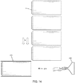
- a dry offset rotary printing or decorating apparatus 10 is illustrated.
- decorated metallic beverage container bodies 14 are delivered from the decorating apparatus 10 via a can chain 16 for further processing.
- a discussion of the dry offset rotary decorating apparatus 10 is set forth in the Background of the Invention and is well-known in the relevant art.
- the process 100 includes a cupper station 116 which deforms a flat metal blank in a drawing process to form a shallow cup 120. Once complete, the shallow cups 120 drop from the cupper station 116 onto a cup conveyor for transfer to the next station.
- the shallow cups 120 are transferred continuously to one or more bodymaker stations 124.
- Each bodymaker station 124 includes tooling for drawing and thinning the shallow cups 120 to form thin-walled tubular co0ntainer bodies 14 having an open end and an opposing closed end, which are joined by a cylindrical side wall.
- Each bodymaker station 124 contains a tool called a punch, which forms the shape of the container body 14 by forcing the cup 120 through a series of progressively smaller circular ironing rings. This action draws the metal up the sides of the punch, ironing it into a container body 14.
- the cup 120 is forced through the rings, its diameter is reduced, its walls are thinned and its height is increased.
- the bottom is formed into a dome shape that strengthens the bottom of the container body 14.
- wall ironing the metal must be lubricated to reduce frictional heat.
- the thin-walled, tubular container bodies 14 are transferred from the bodymakers 124 to trimmer stations. Each trimmer station includes a knife for shearing excess material about the open ends of the tubular container bodies 14. This process adapts the container bodies 14 to a uniform, predetermined height.
- the container bodies 14 are then continuously transferred to a washer station 144.
- the washer removes the forming lubricants before the application of outside decoration (or label) and inside protective coating.
- the washed container bodies 14 are discharged through a dryer station where the container bodies 14 are dried with forced hot air.
- a base layer of coating can be applied to the outer surface of the container bodies 14 at a base coater station.
- the base coating layer is generally a white or clear base coat.
- the container bodies 14 are then continuously transferred to a decorative coating station 156, which includes a decorating apparatus, such as the dry offset rotary decorating apparatus 10 illustrated in FIG. 1 .
- the decorative coating station 156 applies a decorative layer of coating (ink) to the outer surface of the thin-walled tubular container bodies 14.
- the inked container bodies 14 move to a rotating varnish application roll that applies a clear coating over the entire outer sidewall.
- the clear coating protects the ink from scratching and contains lubricants that facilitate can conveying.
- the container bodies 14 are transferred from the decorator 156 onto a pin 20 of a chain 16 (so that only the inside surface is contacted) and is conveyed through a decorator coating, or "pin,” oven/drier station 160 where the ink is dried with forced hot air.
- the container bodies 14 are conveyed to an inner surface coater station.
- This station includes a bank of spray machines that spray the inner surfaces of the container bodies 14 with an epoxy-based organic protective coating.
- the inside coating is also cured by forced hot air at another dryer station 168. The coating prevents the beverage from contacting or reacting with the metal of the inner surface of the container body 14.
- a necker/flanger station 176 reduces the diameter of the open ends of the container bodies 14, and gives the cans the characteristic neck shape.
- the diameter of the top of the can is reduced or "necked-in.”
- the top of the can is flanged outwards to enable the end to be seamed on after the cans are filled with a beverage.
- a finished or substantially finished, as in suitable for use by a beverage manufacturer container body 14 is produced.
- the present invention incorporates an inspection station 200 subsequent to the decorating station 156 in a metallic beverage container body manufacturing process and prior to necking and flanging.
- the inspection station 200 is located after blanking, cupping, body making (also known as draw and iron, "DI"), trimming, washing, and decorating stations, and optionally post-decoration oven station, but prior to necking and flanging stations.
- the metallic beverage container body 14 to be inspected has a cylindrical sidewall separating an open end from an integral closed end wherein a portion of the sidewall immediately adjacent the open end has a circumference that is substantially equal to the circumference of a portion of the sidewall adjacent the integral bottom portion.
- one purpose of the invention is to inspect the quality of the decorations produced on the container bodies 14.
- Another purpose is to inspect the quality of the metal forming of the sidewalls produced by the DI process and subsequent trimming of the container bodies 14.
- the inspection station 200 can identify characteristics that include, but are not limited to, quality of a printed bar code, damaged (e.g. cut or torn) ink transfer blankets, color recognition or variation, alignment of the components of the dry offset rotary decorator, ink splatter, poor overlap (there must be spacing between colors on a container body of about 0.005 inches (0.013mm), generally caused by alignment issues between a transfer blanket and a printing plate), varnish defects, and washer contamination.
- the inspection station 200 can also identify dents and pleats in the metal. From the bodymaker to the trimmer, denting can occur from handling and container body transfer equipment. However, most metal damage, such as dents and pleats, occur later in the container body making process during necking and flanging.
- the inspection station 200 of the present invention replaces the current method of post-decoration inspection which is done by hand (i.e., manually).
- a person randomly samples container bodies by hand post-decoration, and those randomly sampled container bodies must be scrapped.
- the present invention inspects container bodies post-decoration, and the container bodies are returned to the production process.
- the inspection station 200 identifies pre- and post-decoration defects which allows corrective action to take place prior to producing thousands of defective or non-conforming container bodies because, for example, the rate of container body production in a typical process such as the one described herein reaches about 2000 container bodies per minute or 30,000 container bodies in the 15 minutes elapsed time interval that is common under a manual inspection performed by a person.
- the inspection station 200 will be installed as close to the end of the decorating station 156 as possible, to minimize bad (i.e. defective, sub-standard, non-conforming) container body production. By moving the inspection closer to the decorator, fewer "bad cans" are produced prior to discovering and resolving the manufacturing process causing the defects. This station 200 is primarily looking for decoration defects. It has been determined that the preferred location of the inspection station 200 is after the pin oven 160. This inspection station 200 will reduce the number of bad cans that are made.
- the inspection station 200 operates on an indexing operation.
- the indexer can be a turret 206 that sequentially transfers container bodies 14 through the inspection station 200 along an index path in a predetermined, generally constant, orientation, here via counterclockwise rotation.
- the decorated container bodies 14 are fed to the inspection station 200 via an infeed rail 202 to the index path at an entrance positon 204 on a multi-position turret 206 and are discharged from the inspection station 200 at the exit position 212.
- the circumferential turret 206 rotates about a central axis. It has a plurality of pockets 218 adapted, as in sized and shaped, to support, control, and properly retain the sidewall of the container bodies 14 therein in a predetermined orientation and to prevent misalignment of the container body 14 relative to a mandrel 220, which is used during the act of inspecting the container body 14.
- the turret acts as an isolating device to take a container body 14 off of the trackwork, which is used to transport container bodies 14 through this portion of the manufacturing process, and index the container bodies 14 into position for inspection.
- the container bodies 14 are blown onto the mandrel 220 for inspection and blown off of the mandrel 220 back onto the turret 206 after inspection (see, e.g., FIGS. 9-11 ).
- the turret then indexes and while loading one container body 14, it discharges the inspected container body.
- the container bodies 14 are loaded onto the turret 206 at the 10 o'clock position on the turret 206; the turret 206 rotates clockwise; and the container bodies are discharged beyond the 12 o'clock position, which is a dwell position 228.
- container bodies 14 are loaded at the 10 o'clock position, discharged at the 2 o'clock position.
- Rejected container bodies 14 are removed from the manufacturing queue into a chute very near the discharge position.
- the frame of reference is facing the open end of the container body 14 on the turret 206, and the container bodies 14 move towards the viewer as the open ends of the container bodies are loaded onto the mandrel 220.
- container bodies 14 enter the inspection station 200 via the infeed rail 202 and are loaded onto one of a plurality of positions on the turret 206.
- the container bodies 14 are then indexed in a clockwise direction by the turret 206 to the dwell position 228, which is at the 12 o'clock position using a clock-like orientation in the embodiment illustrated and then transferred one at a time onto the mandrel 220 at an inspection position 232.
- the inspection position 232 is vertically aligned with and horizontally offset from the dwell position 210 (see FIG. 9 ).
- Servo technology which employs a servo motor 234a, is used to index the turret 206 towards the inspection position 232 comprising a container body-over-mandrel application.
- the container body 14 is loaded onto the mandrel 220 at the inspection position 232 to reduce container body deformation during spinning.
- Mandrel spinning which is variable and also controlled by a servo motor 234b, transfers spinning to the container body 14 while images of the side wall are being captured. This provides an inspection of an entire circumference of the container body side wall.
- the mandrel 220 provides support for the extremely thin metal, on the order of 0.005 inches (0.13mm) or less, of the container body side wall, so that when the container body 14 is spun, it will not develop mechanical deformities due to forces exerted on the thin-walled side wall during spinning.
- the side wall is not stabilized because it does not yet have a neck of reducing diameter, which is not added or formed at the open end of the side wall until it passes through the necking and flanging stations.
- the container body 14 rotates with rotation of the mandrel 220, at least about 360 degrees. Then, it is indexed to the exit or discharge position 212 wherein it is removed from the inspection station 200 and sent back to a manufacturing queue 22 for further processing (e.g. necking and flanging) or rejected at a rejection position 216 where the container body 14 is removed prior to returning to the manufacturing queue 22.
- the spin speed of the mandrel 220 is variable to match the maximum grip rate of an imager.
- the mandrel rotation speed is variable to minimize image acquisition time. It may be provided by a variable frequency drive. It could also be servo controlled, DC motor controlled, or by other means. The important fact is that the spin speed can be varied.
- the mandrel 220 is similarly shaped to the container bodies 14. Accordingly, it has a generally cylindrical side wall separating a distal end of the mandrel from a proximal end of the mandrel wherein the mandrel 220 is insertable within the metallic beverage container bodies such that the distal end is positioned adjacent an enclosed bottom of the metallic beverage containers and the proximal end is positioned adjacent an open end of the metallic beverage container bodies.
- the proximal end is attached to a shaft which is joined to a motor to drive rotation of the mandrel 220.
- the mandrel 220 spins about a central, generally horizontal, axis 50 which corresponds to a similar axis of the container body when it is located at the dwell positon such that container body transfer from the dwell position 228 to the inspection position 232 is facilitated (see FIG. 9 ).
- the container body 14 is removed from the indexer, in this case the rotary turret 206, and loaded onto the mandrel 220 coincident with the inspection position 232.
- a force F provided by a source fluid pressure 236 causes the container body 14 to be removed from the turret 206 and transferred onto the mandrel 220.
- the force F causes a movement M by a metallic beverage container body 14 which transfers the container body 14 from the indexer 206 at the dwell position 228 onto and over or about the mandrel 220 at the inspection position 232 across the horizontal offset between dwell position 228 and the inspection position 232.
- the imager in this a camera 240, is mounted to the inspection station 200 and pointed at the mandrel 220.
- FIGS. 12 and 13 show a comparative example in which disks or pads 237 are provided as an alternative to the mandrel 220.
- the disks or pads 237 engage the open end and opposing closed end of the container bodies 14.
- the engagement supports the thin-walled side wall through movement from the dwell position to the inspection position and during inspection.
- the pads 237 are further provided to impart rotation to the container bodies 14 during inspection.
- the pads 237 may be attached to shafts which are operatively connected to servo motors 234b to cause the necessary or desired rotation of the container bodies 14 during inspection.
- one or more stepper motors are used instead of servo technology.
- a stepper motor is a polyphase AC synchronous, and it is ideally driven by sinusoidal current.
- Microstepping is often "sine cosine microstepping" in which the winding current approximates a sinusoidal AC waveform. Sine cosine microstepping is the most common form, but other waveforms can be used. Regardless of the waveform used, as the microsteps become smaller, motor operation becomes more smooth, thereby greatly reducing resonance in any parts the motor may be connected to, as well as the motor itself.
- the mandrel 220 spins or rotates about a horizontal axis 50, preferably continuously.
- An encoder activates an inspection window and closes the inspection window. This assures that the camera 240 has captured an image of the container body 14 through 360 degrees of rotation of the cylindrical side wall.
- the encoder measures the degrees of rotation of the mandrel 220 and the container body 14 on the mandrel 220.
- the encoder such as a rotary position sensor, is used to track rotational movement of the mandrel 220.
- a separate encoder tracks movement of the turret 206 and communicates the information to a computer 400 for positional control. In some embodiments, this information is used to make a proper disposition of each container body processed through the inspection station 200, i.e. either pass or fail, reject or return to the queue 22.
- the encoder is used to generate an electrical signal corresponding to a representation of position.
- the encoder is a mechanical component connected directly to the mandrel 220. Approximately every 1/1000 of a revolution, it generates a reading or a signal; however, it can be set at any desired interval, e.g. 10,000 references per revolution. It gives an electrical pulse per percentage of rotation. Based on those pulses, the camera 240 takes a photo so it can capture images over 360 degrees of the container body side wall surface.
- the inspection station 200 includes an image technology to capture and record desired images of the container body 14 with one or more image recorders, preferably digital cameras 240.
- Line scan technology may be employed to take a container body image.
- a snap shot photograph of the container body 14 is taken as the container body 14 is rotated with, or by, the mandrel 220 rotation to capture images of an entire circumference of the container body 14 as the container body 14 completes at least one full rotation about the central, generally horizontal axis of the mandrel 220.
- the container body 14 is rotated about a center horizontal axis 50 at the inspection position 232 wherein the indexer dwells for a predetermined time interval wherein indexing of the container bodies 14 is paused to allow the photographs to be taken as the container body 14 is rotated about a central horizontal axis.
- the present invention preferably employs line scan technology. Approximately 1024 photographs of the container body 14 are taken as it is rotating. The photographs are stitched together using a software routine to produce a composite image of the container body 14. This allows the apparatus to take a strip of the container body 14 at high resolution and build a composite image of 360 degree of the container body 14 one strip at a time. This process allows the current apparatus to detect smaller defects.
- the photographs are collected by a computer system, which may comprise one or more computers 400 and/or controllers in communication with one another and in communication with the camera 240.
- the software routine is stored in a memory on the system. Upon execution of the software routine, the composite image is created and outputted by the software.
- a further software may perform a pass/fail analysis on the composite image or any individual photograph or photographs to determine the quality of the container body decoration and to determine, and report the identity of, the particular transfer blanket or transfer blankets on the dry offset decorating apparatus 10 that produced the defective decoration.
- the individual photographs may capture an image of a section of the circumference of the entire height of the container body 14, from the open end to the enclosed bottom portion.
- the individual photographs may capture an image of a section of a circumference of the container body 14 and only a portion of the height of the container body 14.
- the composite image includes images of at least a portion of the entire height and the entire circumference of the container body 14 stitched together to form the composite image.
- a plurality of images of at least a portion of the height of the container body 14 from the open end to the enclosed end and about the entire circumference of the container body 14 are recorded and processed to arrive at the composite image.
- Container body movement is again actuated by a force provided by a source of fluid pressure 242 associated with the mandrel 220 and the inspection position 232 which causes the inspected container body 14 to transfer from the mandrel 220 across the horizontal offset to the indexer in the dwell position 228, thus back to the index path (see FIG. 10 ).
- the imager utilizes three dimensional technology, wherein the curvature of the cylindrical side wall of the container bodies 14 can be viewed.
- container bodies 14 are discharged from a drier 168 onto a mass conveyor.
- a sample set 300 comprising a fraction, or subset, of a plurality of container bodies 14 in the manufacturing queue 22 is diverted from the manufacturing queue 22 to the inspection station 200.
- the plurality of container bodies may comprise a randomly selected grouping of container bodies; however, more preferably, the number of container bodies 14 in the sample set 300 corresponds to a number of transfer blankets on the dry offset printing apparatus 10 wherein a container body 14 representative of each transfer blanket on the decorator is inspected (i.e., a particular container body that received ink from a particular transfer blanket).
- a dry offset rotary decorator 10 may have from 8 transfer blankets.
- the sample set 300 would include 8 consecutively decorated container bodies 14 wherein 8 container bodies 14 decorated by each of the 8 transfer blankets is represented in the sample set 300. This allows the inspection station 200 to identify the precise transfer blanket that produces each container body 14 in the sample set 300. Thus, if only one or more transfer blankets are torn, damaged, or otherwise producing poor quality container body decorations, by sampling and inspecting 8 consecutive container bodies 14, one can identify the exact transfer blanket or blankets that are performing in a substandard manner.
- rejection of a non-conforming container body takes place on the track work.
- a container body ejection sensor ensures that a container body 14 having a defect is rejected.
- An air knife 248 is used to blow the container body 14 into a reject chute 252.
- a control system flags defective container body 14 as defective as it passes by a sensor. The defective container body 14 is tracked until it reaches the rejection chute 252. When it senses that the defective container body 14 is passing the reject chute 252, the air knife 248 blows the defective container body 14 into the reject chute 252. (See FIG. 14 ).
- a container body 14 approaches the inspection station 200.
- the container body is moved to a dwell position 228 on the inspection station 200.
- the container body 14 is loaded onto the mandrel 220, which is already spinning.
- An imager such as a camera 240, acquires images of the container body 14, a software stored on a memory of on a computer 400 controls processing of the images and comparison of the images against a standard also stored on the memory.
- the container body 14 is blown off the mandrel 220 and indexed or moved from the inspection position 232.
- a software on the computer 400 analyzes whether container body 14 is acceptable or unacceptable by comparing the images to the standard to make a determination whether a decoration on a metallic beverage can body is within the standard.
- a disposition (reject or keep) of the tested container body is determined.
- standard refers to the manufacturing, physical, and visual quality manufacturing tolerance of the container body decoration and, optionally, the condition of the surface shape of the container body.
- the inspection station 200 includes a computer 400 having a software stored in a memory.
- the software compares a composite image of the container body decoration against a standard image of a container body decoration.
- the software compares colors and printed decorations to identify transfer blanket defects, among other defects associated with container body decorating on a dry offset beverage can decorating apparatus.
- the software can identify misalignment issues on the decorated container body (whether overlap is correct) and pattern skew.
- the software also communicates corrective actions that must be taken to correct the defects. If a color variation is detected, either a signal is sent directly to the decorator 156 to make an automatic adjustment using a software or a signal is sent to an operator to make those adjustments manually. Color variation is often due to low ink or low roller pressure.
- the corrective actions would be to add more ink or to adjust the roller pressure. If there is a defect in a transfer blanket, the decorator 156 production may be halted to enable manufacturing personnel to change the transfer blanket and to prevent production of additional non-conforming product. If there are misspellings or wrong product/bar codes, a printing plate would be changed, as the plate must have an error.
- a programmable controller which may be included with the computer 400 is in communication with the inspection station 200 and the one or more servo motors which drive the turret 206 on the inspection station 200. It can be used to program the turret 206 to any predetermined dwell time independent of the speed or rate of container body production or in conjunction therewith to ensure a continuous processing of container bodies 14 through the manufacturing process 100 without any one station moving slower than another.
- the inspection station 200 is not a bottleneck operationally to the process 100.
- inspection station 200 can be programmed based on time without mechanical intervention. This is very important as other technology improves.
- inspection station 200 is fully programmable, and any number of dwell time preferences can be achieved on the same station 200 without the need for mechanical changes to the station 200.
- the controller is capable of synchronizing the movement of the indexer with the overall manufacturing process 100. It generally follows that the programmable controller which may be housed on the computer 400 can be used to control the timing of the inspection station 200 without unnecessarily long dwell times wherein container bodies 14 rest without being formed, reformed, flanged, or inspected. Thus, the computer 400 may have a software routine store on a memory wherein the software routine controls a movement of the indexer.
- One advantage of the present inspection station 200 is that a user can adjust the dwell time for the camera 240 due to servo control. It follows that a user may also slow the rate or dwell down if more time is needed. Thus, a user may increase and decrease the rate as necessary or desired. Therefore, as camera technology improves and images can be obtained in a shorter duration dwell time, the present inspection station 200 can be operated selectively at a faster rate. For example, as the inspection station index rate is increased, the rate at which the container bodies 14 rotate must also be increased to ensure that a least 360 degrees of photos or images are captured about the cylindrical side wall of the container body 14. The adjustability of the dwell and index rate is one of the advantages of the servo technology
- a communication link between the inspection station 200 and a metallic beverage container body decorating station 156.
- This communication link may be provided wirelessly or wired as illustrated.
- the computer 400 may be electrically connected to the inspection station 200 and the decorating station 156.
- a software on the computer 400 controls functionality of the decorating station 156 based on results of the analysis of the images or stitched together images derived at the inspection station 200. Accordingly, a signal may be sent via the communication link to the metallic beverage container body decorating apparatus 10 in response to an output of the software routine.
- This signal may contain information, access information, or activate a software routine that causes an automated change in the operating parameters of the decorating station 156.
- This software and computer 400 closes the loop back to the decorating station 156 to automatically adjust the decorating station 156.
- a software on the computer 400 is used to detect color hue on the container bodies 14, for example wavelength, saturation also called “chroma”, and brightness also called “luminance” or “value,” which is the shade (darkness) or tint (lightness) of a color.
- This software can also close the loop and be used to automatically adjust the decorating station 156 to obtain the correct hue.
- a sensor can be used and directed at a specific portion of the container body 14 to detect color hue.
- a camera 240 does a complete scan of all of the colors on a decorated container body 14 and a software on the computer 240 quantitatively and/or qualitatively analyzes the colors on the container bodies 14 and automatically adjusts the decorating station 156 to correct a non-conforming color characteristic when one arises.
- the camera 240 and software may determine that the color red is light 3%, and automatically adjust the decorating station 156 or decorating apparatus 10.
- proportional integrative derivative (or "PID") is used within the software. PID involves analysis of the container body 14, deciding whether a non-conforming situation exists, determining whether a decorating station 156 change is necessary, making the change, then checking whether the corrective action results in correction of the non-conforming characteristic. Again, this is a closed loop system.
- this is accomplished by performing a line scan label inspection.
- a camera technology that is known to be capable of line scan label inspection is produced by Applied Vision.
- inspection is performed on a sampling basis wherein a sample size (i.e. a fraction, or subset, of the overall number of container bodies in the manufacturing queue 22) of the container bodies 14, for example about 10% of the container bodies in the manufacturing queue 22.
- a sample size i.e. a fraction, or subset, of the overall number of container bodies in the manufacturing queue 22
- fewer than 100% of the container bodies decorated on the decorating apparatus 10 are inspected.
- the sample size is equal to the number of transfer blankets on the dry offset beverage container body decorator 10.
- the sample size includes a number of consecutively decorated container bodies 14 wherein the number is equal to the number of transfer blankets or the number of mandrels on the decorator 10.
- the decorating apparatus 10 has 24 transfer blankets. Therefore, 24 consecutive container bodies from the manufacturing queue 22 are diverted to and through the inspection station 200.
- This sample size and sampling method represents one container body decorated by each of the 24 transfer blankets. This sampling can begin with a container body 14 produced or decorated by any of the transfer blankets as long as all of the transfer blankets are represented in the sample.
- the sampling can begin with a predetermined transfer blanket which facilitates identifying the particular transfer blanket that produced a defectively decorated container body. This can be accomplished by tagging a position on the chain 16, e.g., with an RFID tag or the like 404, and sensing the tag or tags 404 by a position on the decorator, e.g. a particular transfer blanket 408, the identity of which can be stored on the computer 400 along with the chain 16 position of the container body 14 decorated by the particular transfer blanket wherein a plurality of container bodies 14 in the sample set 300 is determined or selected by a software program stored on the memory on the computer 400.
- a predetermined transfer blanket which facilitates identifying the particular transfer blanket that produced a defectively decorated container body. This can be accomplished by tagging a position on the chain 16, e.g., with an RFID tag or the like 404, and sensing the tag or tags 404 by a position on the decorator, e.g. a particular transfer blanket 408, the identity of which can be stored on the computer 400 along with the
- an embodiment of the invention includes tracking an identity or position of at least one of the fraction of the plurality of metallic beverage container bodies in the manufacturing queue 22. Further, the identity or position of the at least one of the fraction of the plurality of metallic beverage is associated with a particular transfer blanket on a dry offset rotary metallic beverage container body decorating apparatus 10. These steps can be performed via software stored on the memory of the computer 400 and the RFID tagging. Tracking a pin or pins on which freshly decorated container bodies are transferred from the decorating station 156.
- the inspection station 200 inspects about 240 cans/minute. In another illustrative example, the inspection station 200 inspects 150 cans/ minute about a full 360 degrees of the circumference of each metallic beverage container body.
- the inspection station 200 runs at 300 cans per minute or more. This is based on the combined move time and dwell time required by the inspection process. As the move time and the dwell time are reduced, throughput is increased. In the future, the inventors contemplate that this invention will be capable of inspecting 400 to 600 containers per minute. If more limited inspection of each container body is performed, the number of inspections may exceed 1000 to 2000 containers per minute. A servo motor is used to control dwell and index time. Thus, the speed of the index and output of the software can be increased with decreased image or photograph acquisition time without swapping out parts of the apparatus.
- the inspection station 200 may be outfitted with a rejection system.
- the can rejection system includes an ejector positioned between the index path and the manufacturing queue 22 for culling an individual container body 14 having a detected defect from the manufacturing stream of sequentially processed beverage containers prior to transferring the container body to a subsequent process.
- the ejector may be a mechanical spring-loaded kick-out, a mechanical arm, pendulum, plunger, piston, plate, or grasping apparatus, or other mechanical system, but is preferably a blow-off nozzle, such as an air knife 252, including a source of fluid pressure in which activation of same is either manually controlled or, more preferably controlled by a signal originating from a software routine stored in the memory on the computer 400 which compares the results of the camera inspection to a quality standard preset by the manufacturer.
- the fluid pressure is activated and delivered through the blow-off nozzle to the container body 14 which thrusts the container body 14 from the indexer to a reject chute and into a waste area, such as waste bin.
- the ejector is located between the index path of the inspection station 200 and the manufacturing queue 22. That is, the ejector is capable of removing a defective container body 14 prior to subsequent steps in the manufacturing process 100. Accordingly, the ejector is located along the circumference of the indexer after the imager but before the transfer wheel or other discharge mechanism.
- an electro-mechanical inspection station 200 comprises a computer 400 having a memory which stores an executable software comprising a first routine controlling mandrel rotation, a second routine controlling movement of the container bodies on the indexer, a third routine controlling the camera 240, a fourth routine comparing beverage container images against a preset quality standard, and a fifth routine for activating removal of a defective container body from the manufacturing queue 22.
- this invention is auto feed into and out of the inspection station 200, inspected container bodies are not destroyed or contaminated by human interaction. Currently most inspection of container bodies is performed manually, so container bodies are discarded if they are touched by a human.
- the present invention increases product reliability. It directly leads to production of fewer non-conforming container bodies because defects are identified sooner and quicker, as is the source of the defects.
- first As used herein, the terms “first,” “second,” “third,” etc. are for illustrative purposes only and are not intended to limit the embodiments in any way. Additionally, the term “plurality” as used herein is intended to indicate any number greater than one, either disjunctively or conjunctively as necessary, up to an infinite number.
- the terms “joined,” “attached,” and/or “connected” as used herein are intended to put or bring two elements together so as to form a unit, and any number of elements, devices, fasteners, etc. may be provided between the joined, attached or connected elements unless otherwise specified by the use of the term “directly” and/or supported by the drawings.
- sequentially aligned is intended to indicate a manufacturing arrangement wherein items of manufacture can be transferred sequentially between manufacturing stations, and any number of manufacturing stations can be sequentially aligned without regard to the order of the manufacturing steps or processes carried out at each manufacturing station.
- computer is intended to include a programmable interface.
Landscapes
- Engineering & Computer Science (AREA)
- Quality & Reliability (AREA)
- Investigating Materials By The Use Of Optical Means Adapted For Particular Applications (AREA)
- Specific Conveyance Elements (AREA)
- Printing Methods (AREA)
Priority Applications (1)
| Application Number | Priority Date | Filing Date | Title |
|---|---|---|---|
| PL17726476T PL3458268T3 (pl) | 2016-05-19 | 2017-05-19 | Urządzenie do kontroli zdobionego metalowego korpusu pojemnika na napoje |
Applications Claiming Priority (2)
| Application Number | Priority Date | Filing Date | Title |
|---|---|---|---|
| US15/159,060 US10549921B2 (en) | 2016-05-19 | 2016-05-19 | Beverage container body decorator inspection apparatus |
| PCT/US2017/033527 WO2017201398A1 (en) | 2016-05-19 | 2017-05-19 | Decorated metallic beverage container body inspection apparatus |
Publications (2)
| Publication Number | Publication Date |
|---|---|
| EP3458268A1 EP3458268A1 (en) | 2019-03-27 |
| EP3458268B1 true EP3458268B1 (en) | 2021-01-27 |
Family
ID=58794221
Family Applications (1)
| Application Number | Title | Priority Date | Filing Date |
|---|---|---|---|
| EP17726476.9A Not-in-force EP3458268B1 (en) | 2016-05-19 | 2017-05-19 | Decorated metallic beverage container body inspection apparatus |
Country Status (10)
| Country | Link |
|---|---|
| US (1) | US10549921B2 (pl) |
| EP (1) | EP3458268B1 (pl) |
| AU (1) | AU2017268442B2 (pl) |
| BR (1) | BR112018072991A2 (pl) |
| CA (1) | CA3023936C (pl) |
| ES (1) | ES2865512T3 (pl) |
| MX (1) | MX2018014077A (pl) |
| PL (1) | PL3458268T3 (pl) |
| RU (1) | RU2707796C1 (pl) |
| WO (1) | WO2017201398A1 (pl) |
Families Citing this family (15)
| Publication number | Priority date | Publication date | Assignee | Title |
|---|---|---|---|---|
| US9555616B2 (en) | 2013-06-11 | 2017-01-31 | Ball Corporation | Variable printing process using soft secondary plates and specialty inks |
| ES2734983T3 (es) | 2014-12-04 | 2019-12-13 | Ball Beverage Packaging Europe Ltd | Aparato de impresión |
| US10549921B2 (en) | 2016-05-19 | 2020-02-04 | Rexam Beverage Can Company | Beverage container body decorator inspection apparatus |
| MX2019000614A (es) * | 2016-07-20 | 2019-07-04 | Ball Corp | Sistema y metodo para alinear un entintador de un decorador. |
| US11034145B2 (en) * | 2016-07-20 | 2021-06-15 | Ball Corporation | System and method for monitoring and adjusting a decorator for containers |
| US10739705B2 (en) | 2016-08-10 | 2020-08-11 | Ball Corporation | Method and apparatus of decorating a metallic container by digital printing to a transfer blanket |
| MX395129B (es) | 2016-08-10 | 2025-03-24 | Ball Corp | Metodo y aparato para decorar un recipiente metalico por impresion digital a una manta de transferencia. |
| EP3740383A4 (en) | 2018-01-19 | 2021-10-20 | Ball Corporation | SYSTEM AND METHOD FOR MONITORING AND ADJUSTING A DECORATING DEVICE FOR CONTAINERS |
| US11534817B2 (en) * | 2018-05-11 | 2022-12-27 | Stolle Machinery Company, Llc | Infeed assembly full inspection assembly |
| WO2020146713A1 (en) | 2019-01-11 | 2020-07-16 | Ball Corporation | Closed-loop feedback printing system |
| US11338566B2 (en) * | 2019-12-10 | 2022-05-24 | Stolle Machinery Company, Llc | Image control system and can decorator employing same |
| CN112660721A (zh) * | 2020-12-25 | 2021-04-16 | 佛山阿尔科工业设备制造有限公司 | 一种罐体输送系统 |
| KR102571748B1 (ko) * | 2021-05-04 | 2023-08-25 | 세메스 주식회사 | 기판 처리 장치 및 방법 |
| US12502884B2 (en) * | 2023-04-25 | 2025-12-23 | Stolle Machinery Company, Llc | Can decorator inspection and control system and adjustment assemblies |
| US20250012923A1 (en) * | 2023-07-07 | 2025-01-09 | Stolle Machinery Company, Llc | Lidar defect detection system and method for use in can manufacturing assemblies |
Family Cites Families (234)
| Publication number | Priority date | Publication date | Assignee | Title |
|---|---|---|---|---|
| US42715A (en) | 1864-05-10 | Improved bread-cutter | ||
| US3098564A (en) | 1961-08-18 | 1963-07-23 | Anchor Hocking Glass Corp | Automatic container inspection machine |
| US3252410A (en) | 1963-10-28 | 1966-05-24 | Thomas A Stephenson | Method for producing printed relief impressions on paper |
| US3286302A (en) | 1963-12-26 | 1966-11-22 | Industrial Nucleonics Corp | Control system for maximizing the production of a material forming process |
| US3313409A (en) | 1964-02-07 | 1967-04-11 | Owens Illinois Inc | Apparatus for inspecting glassware |
| US3262460A (en) | 1964-02-17 | 1966-07-26 | Cincinnati Cleaning And Finish | Conveyor type cleaning device for fragile containers and the like |
| US3357950A (en) | 1965-06-17 | 1967-12-12 | Procter & Gamble | Process for making a resinous dentifrice cleaning agent |
| US3504390A (en) | 1968-05-08 | 1970-04-07 | Cornell Wing | Apparatus for washing cartons |
| GB1298207A (en) | 1968-12-02 | 1972-11-29 | New Jersey Machine Corp | Printing apparatus |
| US3752073A (en) | 1971-04-26 | 1973-08-14 | Bernard Olcott Atlantic Highla | Process for single-impression multicolor printing |
| US3766851A (en) | 1971-11-15 | 1973-10-23 | Sun Chemical Corp | Continuous can printer and handling apparatus |
| US3991673A (en) | 1972-08-02 | 1976-11-16 | St. Regis Paper Company | Nonfabric engraving blanket |
| DE2312596C3 (de) | 1973-03-14 | 1979-06-07 | Feldmuehle Ag, 4000 Duesseldorf | Zwischenträgerblatt für Vervielfältigungen im Klein-Offsetdruckverfahren |
| US3782542A (en) | 1973-04-23 | 1974-01-01 | H Scribner | Automatic bottle thread inspection apparatus |
| US3923158A (en) | 1973-06-20 | 1975-12-02 | Platmanufaktur Ab | On-line multistation inspection device for machine moulded products |
| US3952698A (en) | 1973-09-27 | 1976-04-27 | Kaiser Aluminum & Chemical Corporation | Can treating system |
| US3983729A (en) | 1975-02-03 | 1976-10-05 | National Can Corporation | Method and apparatus for necking and flanging containers |
| US4048917A (en) | 1975-09-26 | 1977-09-20 | Sun Chemical Corporation | Continuous motion printing apparatus |
| US4105122A (en) | 1976-11-26 | 1978-08-08 | Borden, Inc. | Inspecting cans for openings with light |
| US4142462A (en) | 1977-05-11 | 1979-03-06 | International Paper Company | Halftone printing method |
| US4319930A (en) | 1980-03-28 | 1982-03-16 | Daiwa Can Company, Limited | Method for multi-stage washing |
| US4327756A (en) | 1980-05-19 | 1982-05-04 | Metalwash Machinery Corp. | Cleaning machine |
| EP0047165B1 (en) | 1980-09-03 | 1984-11-28 | Crosfield Electronics Limited | Improvements relating to rotary printing presses |
| US4378493A (en) | 1980-11-03 | 1983-03-29 | Owens-Illinois, Inc. | Glass container sidewall defect detection system with a diffused and controlled light source |
| US4442934A (en) | 1980-11-03 | 1984-04-17 | Owens-Illinois, Inc. | Glass container inspection handling system |
| US4384518A (en) | 1980-12-01 | 1983-05-24 | Remington Arms Company, Inc. | Dry offset printer for cylindrical objects |
| CH654524A5 (en) | 1981-02-16 | 1986-02-28 | Polytype Ag | Printing machine having a plurality of forme cylinders assigned to a central impression cylinder |
| US4492476A (en) | 1981-02-20 | 1985-01-08 | Kirin Beer Kabushiki Kaisha | Defect detecting method and apparatus |
| US4519310A (en) | 1981-04-27 | 1985-05-28 | Daiwa Can Company, Limited | Method of multi-color printing on cylindrical container |
| GB2097331B (en) | 1981-04-28 | 1985-03-20 | Daiwa Can Co Ltd | Method of multicolour printing on cylindrical containers |
| US4374681A (en) | 1981-05-11 | 1983-02-22 | Coral Chemical Company | System for controlling the composition of chemical treatment baths |
| US4399357A (en) | 1981-05-22 | 1983-08-16 | Owens-Illinois, Inc. | Method and apparatus for inspecting glass containers |
| JPS5849256A (ja) | 1981-09-18 | 1983-03-23 | Shin Nippon Koki Kk | 円筒状物品胴部外周面の多色印刷機械における自動見当合せ装置 |
| DE3140122C2 (de) | 1981-10-09 | 1987-11-12 | Continental Gummi-Werke Ag, 3000 Hannover | Mehrschichtiges Drucktuch und Verfahren zu dessen Herstellung |
| DE3276471D1 (en) | 1981-10-10 | 1987-07-09 | Basf Lacke & Farben | Flat-bed printing method |
| US4479429A (en) | 1982-03-22 | 1984-10-30 | Yoshino America Corporation | Multi-color printing apparatus of surfaces of bodies of rotation |
| US4732027A (en) | 1982-12-27 | 1988-03-22 | American National Can Company | Method and apparatus for necking and flanging containers |
| US4519232A (en) | 1982-12-27 | 1985-05-28 | National Can Corporation | Method and apparatus for necking containers |
| US4774839A (en) | 1982-12-27 | 1988-10-04 | American National Can Company | Method and apparatus for necking containers |
| US5497900A (en) | 1982-12-27 | 1996-03-12 | American National Can Company | Necked container body |
| DE3336193C2 (de) | 1983-10-05 | 1986-02-27 | M.A.N.- Roland Druckmaschinen AG, 6050 Offenbach | Gummituch für eine Offsetrotationsdruckmaschine |
| FR2558259B1 (fr) | 1984-01-17 | 1986-12-12 | Saint Gobain Cinematique Contr | Emetteur a balayage pour l'inspection optique d'articles transparents |
| US4616306A (en) | 1984-08-10 | 1986-10-07 | Amchem Products, Inc. | Metal treating process control |
| DE3687427T2 (de) | 1985-05-22 | 1993-05-06 | Toyo Seikan Kaisha Ltd | Verfahren fuer gedruckte, durch ziehen geformte koerper und durch dieses verfahren geformtes gefaess. |
| US5049432B1 (en) | 1985-09-11 | 1995-06-20 | Porelon | Method for preparing a marking structure |
| DE3621976A1 (de) | 1986-07-01 | 1988-01-07 | Kronseder Maschf Krones | Verfahren und vorrichtung zum pruefen von leeren getraenkeflaschen oder dgl. |
| US4741266A (en) | 1986-10-08 | 1988-05-03 | Adolph Coors Company | Can decorating apparatus |
| US4884504A (en) | 1987-08-14 | 1989-12-05 | Ian Sillars | Method for printing of quasi random number tables on cylindrical objects |
| DE8715505U1 (de) | 1987-11-23 | 1988-02-18 | LMB Medizin Technik GmbH, 8059 Oberding | Reaktionsgefäß zur Untersuchung flüssiger Proben im Mikroliterbereich |
| US5181471A (en) | 1988-01-11 | 1993-01-26 | Ian Sillars | Combined offset and flexographic printing and decorating system |
| JPH0782542B2 (ja) | 1988-01-29 | 1995-09-06 | 株式会社スキャンテクノロジー | 印字検査方法、印字検査装置および印刷物自動振分けシステム |
| EP0332376A3 (en) | 1988-03-07 | 1990-10-10 | Sentinel Vision Inc. | Apparatus for inspecting can seams and the like |
| US4898752A (en) | 1988-03-30 | 1990-02-06 | Westvaco Corporation | Method for making coated and printed packaging material on a printing press |
| JPH0627717B2 (ja) | 1988-04-13 | 1994-04-13 | 株式会社キリンテクノシステム | 壜の胴部検査装置 |
| US5282306A (en) | 1988-06-15 | 1994-02-01 | Toyo Seikan Kaisha, Ltd. | Process for the preparation of a draw-formed printed can |
| US4889560A (en) | 1988-08-03 | 1989-12-26 | Tektronix, Inc. | Phase change ink composition and phase change ink produced therefrom |
| US4911075A (en) | 1988-08-19 | 1990-03-27 | Presstek, Inc. | Lithographic plates made by spark discharges |
| US4924107A (en) | 1988-10-07 | 1990-05-08 | Ball Corporation | System for inspecting the inside surfaces of a container for defects and method therefor |
| JPH07102733B2 (ja) | 1989-03-13 | 1995-11-08 | 大和製罐株式会社 | 円筒形容器外面への非重ね刷り網点印刷方法 |
| US5065905A (en) | 1990-05-23 | 1991-11-19 | Xerox Corporation | Hardware delivery system |
| WO1992007716A1 (en) | 1990-11-01 | 1992-05-14 | Landsman Robert M | Printing press |
| WO1992018557A1 (en) | 1991-04-09 | 1992-10-29 | Repap Technologies Inc. | Improved lignin-based wood adhesives |
| US5120126A (en) | 1991-06-14 | 1992-06-09 | Ball Corporation | System for non-contact colored label identification and inspection and method therefor |
| JP2754300B2 (ja) | 1991-12-06 | 1998-05-20 | 大和製罐株式会社 | Di缶表面処理方法およびその装置 |
| DE69225201T2 (de) | 1991-12-03 | 1998-08-13 | Crown Cork & Seal Co | Verfahren und Vorrichtung zum Bedrucken vonmehrfarbigen Zuschnitten für Behältermäntel in einem einzigen Durchgang |
| US5213043A (en) | 1992-03-20 | 1993-05-25 | Reimers Gary L | Non-film lithographic imaging |
| AU674518B2 (en) | 1992-07-20 | 1997-01-02 | Presstek, Inc. | Lithographic printing plates for use with laser-discharge imaging apparatus |
| US5351617A (en) | 1992-07-20 | 1994-10-04 | Presstek, Inc. | Method for laser-discharge imaging a printing plate |
| US5353703A (en) | 1992-09-29 | 1994-10-11 | Rieker Paul T | Multi-color, single-plate printing press |
| US5502476A (en) | 1992-11-25 | 1996-03-26 | Tektronix, Inc. | Method and apparatus for controlling phase-change ink temperature during a transfer printing process |
| US5337659A (en) | 1993-02-22 | 1994-08-16 | Sequa Corporation | Apparatus and method utilizing continuous motion offset and direct printing techniques for decorating cylindrical containers |
| US5997849A (en) | 1993-12-29 | 1999-12-07 | Chromatic Technologies, Inc. | Thermochromic ink formulations, nail lacquer and methods of use |
| US5591255A (en) | 1993-12-29 | 1997-01-07 | Chromatic Technologies, Inc. | Thermochromic ink formulations, nail lacquer and methods of use |
| US5469787A (en) | 1994-03-15 | 1995-11-28 | Heath Custom Press, Inc. | Multi-color printing press |
| US5987161A (en) | 1994-06-30 | 1999-11-16 | Texas Instruments Incorporated | Apparatus and method for identifying defective objects |
| US5591462A (en) | 1994-11-21 | 1997-01-07 | Pressco Technology, Inc. | Bottle inspection along molder transport path |
| EP0717320B1 (en) | 1994-12-13 | 1999-09-08 | MacDermid Imaging Technology Inc. | Soft relief photopolymer printing plates for flexographic printing |
| US6238837B1 (en) | 1995-05-01 | 2001-05-29 | E.I. Du Pont De Nemours And Company | Flexographic element having an infrared ablatable layer |
| CA2226473A1 (en) | 1995-06-07 | 1996-12-19 | Pressco Technology, Inc. | Inspection system for exterior article surfaces |
| US5713288A (en) | 1995-08-03 | 1998-02-03 | Frazzitta; Joseph R. | Method and apparatus for use in offset printing |
| US6594927B2 (en) | 1995-08-24 | 2003-07-22 | Magiccom | Label or wrapper with premium |
| JP3042395B2 (ja) | 1996-02-05 | 2000-05-15 | 東洋製罐株式会社 | 缶ボトムチャック |
| JPH09295396A (ja) | 1996-04-30 | 1997-11-18 | Mitsubishi Materials Corp | 缶の印刷装置 |
| US5740727A (en) | 1996-06-12 | 1998-04-21 | Coors Brewing Company | Can decorating apparatus |
| US5919839A (en) | 1996-06-28 | 1999-07-06 | Tektronix, Inc. | Phase change ink formulation using an isocyanate-derived wax and a clear ink carrier base |
| US6312872B1 (en) | 1997-10-24 | 2001-11-06 | Macdermid Graphic Arts | Composite relief image printing plates |
| US5908505A (en) | 1996-09-10 | 1999-06-01 | Questech, Inc. | High volume, textured liquid transfer surface |
| US5970865A (en) | 1997-02-26 | 1999-10-26 | Mitsubishi Materials Corporation | Apparatus and method for printing multi-color images onto cylindrical body |
| EP0968491B1 (en) | 1997-03-17 | 2002-05-02 | Magiccom | Label or wrapper with premium |
| DE19715169A1 (de) | 1997-04-11 | 1998-10-15 | Basf Drucksysteme Gmbh | Lichtempfindliches Gemisch und daraus hergestelltes Aufzeichungungsmaterial |
| US6145565A (en) | 1997-05-22 | 2000-11-14 | Fromson; Howard A. | Laser imageable printing plate and substrate therefor |
| US5974974A (en) | 1997-07-01 | 1999-11-02 | Polyfibron Technologies, Inc. | Substantially transparent printing blankets and methods for using same |
| US5806427A (en) | 1997-08-29 | 1998-09-15 | Goss Graphic Systems, Inc. | Printing press having carriage mounted interchangeable plate cylinders |
| US6196675B1 (en) | 1998-02-25 | 2001-03-06 | Xerox Corporation | Apparatus and method for image fusing |
| US6079326A (en) | 1998-05-15 | 2000-06-27 | Carl Strutz & Co., Inc. | Method and apparatus for using workpiece registration to inline decorate and cure workpieces |
| JP2000121580A (ja) | 1998-08-11 | 2000-04-28 | Hitachi Ltd | X線缶巻締部測定装置及び測定開始点検出方法 |
| IT1305329B1 (it) | 1998-10-22 | 2001-05-04 | Omso Spa | Dispositivo automatico di rilevazione della qualita' di stampa suflaconi o bottiglie di forma qualunque |
| US6058839A (en) | 1998-11-10 | 2000-05-09 | Frazzitta; Joseph R. | Computerized cutting method and apparatus for use in printing operations |
| GB9828333D0 (en) | 1998-12-23 | 1999-02-17 | Crown Cork & Seal Tech Corp | Rinsing device |
| FR2789347B1 (fr) | 1999-02-04 | 2001-04-06 | Rollin Sa | Blanchet a proprietes de surface variables pour machine a imprimer |
| JP2000258899A (ja) | 1999-03-05 | 2000-09-22 | Konica Corp | 平版印刷版材料及び印刷方法 |
| US6731405B2 (en) | 1999-05-14 | 2004-05-04 | Artwork Systems | Printing plates containing ink cells in both solid and halftone areas |
| US6174937B1 (en) | 1999-07-16 | 2001-01-16 | Xerox Corporation | Composition of matter, a phase change ink, and a method of reducing a coefficient of friction of a phase change ink formulation |
| JP3473513B2 (ja) | 1999-07-27 | 2003-12-08 | 東洋製罐株式会社 | 缶胴への印刷方法 |
| NL1012832C2 (nl) | 1999-08-16 | 2001-02-19 | Automation Equipment | Multi-station druksysteem voor cilindrische of afgeknot-kegelvormige producten. |
| CA2318700A1 (en) | 1999-09-17 | 2001-03-17 | Katsuyuki Fujita | Thermochromic microencapsulated pigments |
| US6309453B1 (en) | 1999-09-20 | 2001-10-30 | Xerox Corporation | Colorless compounds, solid inks, and printing methods |
| DE19950605A1 (de) | 1999-10-21 | 2001-04-26 | Heidelberger Druckmasch Ag | Gummituch mit Registerausnehmungen und Verfahren zur Gummituchausrichtung |
| IL133355A (en) | 1999-12-07 | 2003-10-31 | Creo Il Ltd | Method and plate for digitally-imaged offset printing |
| US6551422B1 (en) | 1999-12-17 | 2003-04-22 | Coral Chemical Company | Method and apparatus for treating metal |
| US6779445B2 (en) | 2000-01-25 | 2004-08-24 | Koenig & Bauer Aktiengesellschaft | Intaglio printer |
| US6473169B1 (en) | 2000-05-03 | 2002-10-29 | Air Logic Power Systems, Inc. | Integrated leak and vision inspection system |
| US6543350B2 (en) | 2000-05-19 | 2003-04-08 | Intelligent Sensing, Inc. | Measurement system to monitor printing contact pressure |
| DE10029181A1 (de) | 2000-06-14 | 2001-12-20 | Balsfulland Maschfabrik Gmbh | Vorrichtung zum Dekorieren von Einzelobjekten |
| US6525333B1 (en) | 2000-07-18 | 2003-02-25 | Intelligent Machine Concepts, L.L.C. | System and method for inspecting containers with openings with pipeline image processing |
| US6474231B1 (en) | 2000-07-26 | 2002-11-05 | Heidelberger Druckmaschinen Ag | Multi-color printing press with common blanket cylinder |
| US6655281B1 (en) | 2000-08-08 | 2003-12-02 | 3M Innovative Properties Company | Flexographic printing elements with improved air bleed |
| US6779455B2 (en) | 2000-09-28 | 2004-08-24 | Creo Il Ltd. | Method of printing variable information |
| JP2002156338A (ja) | 2000-11-15 | 2002-05-31 | Lion Engineering Co Ltd | 缶蓋接合部の検査装置 |
| CA2430101C (en) | 2000-11-28 | 2009-05-26 | Asahi Kasei Kabushiki Kaisha | Improved photosensitive resin for flexographic printing developable with an aqueous developer solution |
| US6494961B2 (en) | 2001-03-30 | 2002-12-17 | Alcan International Limited | Method of controlling solution concentration in strip cleaning line |
| US6584989B2 (en) | 2001-04-17 | 2003-07-01 | International Business Machines Corporation | Apparatus and method for wet cleaning |
| ATE282527T1 (de) | 2001-05-25 | 2004-12-15 | Stork Prints Austria Gmbh | Verfahren und vorrichtund zur herstellung einer druckform |
| US7011728B2 (en) | 2001-07-19 | 2006-03-14 | Berry Plastics Corporation | Container-labeling and-printing synchronization apparatus and process |
| US20030024554A1 (en) | 2001-08-03 | 2003-02-06 | Schultz Robert H. | Object washing apparatus |
| US20030179920A1 (en) | 2002-03-13 | 2003-09-25 | Intelligent Machine Concepts, L.L.C. | Inspection system for determining object orientation and defects |
| DE10225198B4 (de) | 2002-06-06 | 2007-07-12 | Polytype S.A. | Verfahren und Vorrichtung zum Drucken eines mehrfarbigen Bildes |
| DE10226500B4 (de) | 2002-06-14 | 2010-04-22 | Ball Packaging Europe Holding Gmbh & Co. Kg | Vorrichtung zur Oberflächenbearbeitung von Teilen |
| US6984478B2 (en) | 2002-09-16 | 2006-01-10 | E.I. Du Pont De Nemours And Company | Print control for flexographic printing |
| US7399526B2 (en) | 2002-10-11 | 2008-07-15 | Day International, Inc. | Printing blanket and method for reducing corrosion and abrasion of printing blankets and blanket cylinders |
| CA2504053A1 (en) | 2002-11-08 | 2004-05-27 | Pressco Technology Inc. | System and method for associating container defect information to a specific path of manufacturing |
| EP1445098A1 (en) | 2003-02-04 | 2004-08-11 | Kba-Giori S.A. | Blanket cylinder for an intaglio printing machine |
| JP2004295009A (ja) | 2003-03-28 | 2004-10-21 | Fuji Photo Film Co Ltd | 平版印刷版の製版方法 |
| US7396475B2 (en) | 2003-04-25 | 2008-07-08 | Molecular Imprints, Inc. | Method of forming stepped structures employing imprint lithography |
| WO2005005147A1 (ja) | 2003-07-09 | 2005-01-20 | Asahi Kasei Chemicals Corporation | シームレス印刷用凸版材の製造方法及びシームレス印刷用凸版材の製造装置 |
| US6920822B2 (en) | 2003-09-03 | 2005-07-26 | Stolle Machinery Company, Llc | Digital can decorating apparatus |
| US8904931B2 (en) | 2003-11-10 | 2014-12-09 | Day International, Inc. | Printing blanket construction and method of making |
| US7309563B2 (en) | 2003-12-19 | 2007-12-18 | Palo Alto Research Center Incorporated | Patterning using wax printing and lift off |
| NL1025332C2 (nl) | 2004-01-27 | 2005-08-02 | Heineken Tech Services | Inrichting en werkwijze voor het detecteren van vervuiling in een houder. |
| DE202004007783U1 (de) | 2004-05-12 | 2005-09-15 | Krones Ag | Inspektionsvorrichtung |
| US7394937B2 (en) | 2004-05-19 | 2008-07-01 | Applied Vision Company, Llc | Vision system and method for process monitoring |
| US7313270B2 (en) | 2004-05-19 | 2007-12-25 | Applied Vision Company, Llc | Vision system and method for process monitoring |
| JP2006027209A (ja) | 2004-07-21 | 2006-02-02 | Konica Minolta Medical & Graphic Inc | 平版印刷版材料及び平版印刷版、並びにそれを用いた印刷方法 |
| EP1630600A3 (en) | 2004-07-29 | 2006-03-22 | Rohm and Haas Electronic Materials, L.L.C. | Hot melt composition and method involving forming a masking pattern |
| WO2006048022A2 (en) | 2004-11-08 | 2006-05-11 | Superfos A/S | An apparatus for printing images on the annular sidewall of a formstable plastics container |
| US7308142B2 (en) | 2005-03-10 | 2007-12-11 | Applied Vision Company, Llc | System and methods for rogue can detection |
| DE102006025897A1 (de) | 2005-06-22 | 2007-01-04 | Heidelberger Druckmaschinen Ag | Druckwerk mit einem in Umfangsrichtung Formzylinderabschnitte aufweisenden Formzylinder |
| JP4580830B2 (ja) | 2005-07-08 | 2010-11-17 | 株式会社日立製作所 | 画像形成方法及びそれを用いた画像形成装置 |
| JP5256572B2 (ja) | 2005-09-15 | 2013-08-07 | 凸版印刷株式会社 | 印刷方法 |
| US20070084368A1 (en) | 2005-10-13 | 2007-04-19 | Ryan Vest | Dynamic UV-exposure and thermal development of relief image printing elements |
| JP2007185917A (ja) | 2006-01-16 | 2007-07-26 | Asahi Kasei Chemicals Corp | フレキソ印刷用印刷版の製造方法 |
| JP2007223106A (ja) | 2006-02-22 | 2007-09-06 | Universal Seikan Kk | ドライオフセット印刷方法およびドライオフセット印刷装置 |
| JP2007245449A (ja) | 2006-03-15 | 2007-09-27 | Toppan Printing Co Ltd | 印刷版の製造方法および有機elパネル製造方法 |
| NL1031853C2 (nl) | 2006-05-22 | 2007-11-23 | Eagle Vision Systems B V | Werkwijze en inrichting voor het detecteren van een ongewenst object of defect. |
| US20070289905A1 (en) | 2006-06-20 | 2007-12-20 | Biofuels Automation, Inc. | System for managing solution for cleaning fermentation tanks |
| FR2905630B1 (fr) | 2006-09-12 | 2010-01-22 | Impika | Dispositif d'impression par transfert sur un support d'impression cylindrique |
| DE102007005340B4 (de) | 2007-02-02 | 2009-12-03 | Polytype Converting S.A. | Druckverfahren und Vorrichtung zum Bedrucken von Hohlkörpern |
| US7691549B1 (en) | 2007-02-15 | 2010-04-06 | Kla-Tencor Technologies Corporation | Multiple exposure lithography technique and method |
| JP2008249668A (ja) | 2007-03-30 | 2008-10-16 | Universal Seikan Kk | 缶の巻き締め検査装置並びに巻き締め検査方法 |
| US7684034B2 (en) | 2007-05-24 | 2010-03-23 | Applied Vision Company, Llc | Apparatus and methods for container inspection |
| US7667836B2 (en) | 2007-05-24 | 2010-02-23 | Applied Vision Company, Llc | Apparatus and methods for container inspection |
| US8014586B2 (en) | 2007-05-24 | 2011-09-06 | Applied Vision Corporation | Apparatus and methods for container inspection |
| KR101153104B1 (ko) | 2007-08-03 | 2012-06-04 | 케이에이치에스 게엠베하 | 용기에 인쇄를 하기 위한 장치 및 방법 |
| JP4916516B2 (ja) | 2007-10-04 | 2012-04-11 | 武内プレス工業株式会社 | 加飾容器の製造方法 |
| FR2922900B1 (fr) | 2007-10-30 | 2009-12-11 | Cogia | Dispositif de maintien du frisage de fibres textiles ou de fils lors du traitement de fixage ulterieur. |
| US8409698B2 (en) | 2007-11-30 | 2013-04-02 | Day International, Inc. | Image transfer product including a thin printing surface layer |
| EP2080570A1 (en) | 2008-01-18 | 2009-07-22 | Rexam Beverage Can Europe Limited | Printing plates |
| EP2246191B1 (en) | 2008-02-28 | 2018-08-15 | Universal Can Corporation | Printing plate cylinder, printing apparatus, and method for producing printing plate cylinder |
| JP5097594B2 (ja) | 2008-03-28 | 2012-12-12 | ユニバーサル製缶株式会社 | 印刷版胴及び缶の印刷装置 |
| US8544385B2 (en) | 2008-05-15 | 2013-10-01 | Goss International Americas, Inc. | Printing press with different fixed cutoffs and method |
| JP2009292041A (ja) | 2008-06-05 | 2009-12-17 | Sony Corp | 熱転写ラミネートフィルム、熱転写シートおよび画像形成装置 |
| US7810922B2 (en) | 2008-07-23 | 2010-10-12 | Xerox Corporation | Phase change ink imaging component having conductive coating |
| JP2010036518A (ja) | 2008-08-07 | 2010-02-18 | Lifcom:Kk | ブランケット胴 |
| EP2153991B1 (en) | 2008-08-11 | 2011-08-03 | Agfa Graphics N.V. | Imaging apparatus and method for making flexographic printing masters |
| JP2010058399A (ja) | 2008-09-04 | 2010-03-18 | Toyo Seikan Kaisha Ltd | シームレス缶、印刷版、シームレス缶用曲面印刷機、シームレス缶への印刷方法、及びシームレス缶の製造方法 |
| JP2010064450A (ja) | 2008-09-12 | 2010-03-25 | Asahi Kasei E-Materials Corp | レーザー彫刻印刷版の製造方法 |
| JP2010069836A (ja) | 2008-09-22 | 2010-04-02 | Asahi Kasei E-Materials Corp | レーザー彫刻印刷原版の製造方法及びレーザー彫刻印刷版の製造方法 |
| JP5210949B2 (ja) | 2009-04-10 | 2013-06-12 | ユニバーサル製缶株式会社 | 缶体検査装置及び缶体検査方法 |
| DE102009003817A1 (de) | 2009-04-23 | 2010-10-28 | Contitech Elastomer-Beschichtungen Gmbh | Mehrschichtiges Flächengebilde in Form eines Drucktuches oder einer Druckplatte für den Flexo-und Hochdruck mit einer Lasergravur |
| EP2432639A4 (en) | 2009-05-21 | 2013-05-29 | Inx Internat Ink Company | APPARATUS FOR PRINTING ON GLOBALLY CYLINDRICALLY OBJECTS AND RELATED METHODS |
| US9016293B2 (en) | 2009-08-21 | 2015-04-28 | Gas Turbine Efficiency Sweden Ab | Staged compressor water wash system |
| DE102009043921A1 (de) | 2009-09-01 | 2011-03-03 | Contitech Elastomer-Beschichtungen Gmbh | Mehrschichtiges Flächengebilde und Verfahren zu dessen Herstellung |
| US9720326B2 (en) | 2009-10-01 | 2017-08-01 | David A. Recchia | Method of improving print performance in flexographic printing plates |
| US8820234B2 (en) | 2009-10-30 | 2014-09-02 | Esko-Graphics Imaging Gmbh | Curing of photo-curable printing plates with flat tops or round tops by variable speed exposure |
| JP5029853B2 (ja) | 2010-03-10 | 2012-09-19 | 東洋製罐株式会社 | キャップ殺菌洗浄装置及び殺菌洗浄方法 |
| JP5049366B2 (ja) | 2010-03-29 | 2012-10-17 | 富士フイルム株式会社 | レーザー彫刻型フレキソ印刷版原版 |
| JP5497525B2 (ja) | 2010-04-20 | 2014-05-21 | 富士フイルム株式会社 | 印刷用凸版作成装置、システム、方法及びプログラム |
| EP2384890B8 (en) | 2010-05-07 | 2013-10-09 | KBA-NotaSys SA | Impression cylinder for intaglio printing and intaglio printing process |
| JP5438593B2 (ja) | 2010-05-18 | 2014-03-12 | 株式会社小森コーポレーション | グラビアオフセット印刷機 |
| DE102010031527A1 (de) | 2010-07-19 | 2012-01-19 | Flint Group Germany Gmbh | Verfahren zur Herstellung von Flexodruckformen umfassend die Bestrahlung mit UV-LEDs |
| DE102010032410B4 (de) | 2010-07-27 | 2014-11-13 | Mall + Herlan Schweiz Ag | Inspektionsvorrichtung, Fertigungsanlage mit Inspektionsvorrichtung und Inspektionsverfahren für Gefäße |
| US8408130B2 (en) | 2010-08-25 | 2013-04-02 | Eastman Kodak Company | Method of making flexographic printing members |
| DE102010037865B4 (de) | 2010-09-29 | 2014-01-23 | Contitech Elastomer-Beschichtungen Gmbh | Drucktucheinheit |
| JP6181556B2 (ja) | 2010-10-19 | 2017-08-16 | プレスコ テクノロジー インコーポレーテッドPressco Technology Inc. | デコレータ構成部品の識別及びその選択調整のための方法及びシステム |
| JP5724285B2 (ja) | 2010-10-19 | 2015-05-27 | 東洋製罐株式会社 | 印刷シームレス缶及びその製造方法 |
| US20120238675A1 (en) | 2011-03-17 | 2012-09-20 | Inx International Ink Co. | Method of producing an ink composition for offset printing |
| WO2012149187A1 (en) | 2011-04-26 | 2012-11-01 | Lacaze John R | Apparatuses for printing on generally cylindrical objects and related methods |
| US9475276B2 (en) | 2011-04-27 | 2016-10-25 | Stolle Machinery Company, Llc | Can decorator machine, ink station assembly therefor, and can decorating method employing same |
| CA2835850A1 (en) | 2011-05-13 | 2012-11-22 | Terrill Scott Clayton | Scented thermochromic ink |
| EP2748806A1 (en) | 2011-08-22 | 2014-07-02 | Chromatic Technologies, Inc. | Variable printing of thermochromic codes |
| US20140210201A1 (en) | 2011-08-22 | 2014-07-31 | Chromatic Technologies Inc. | Variable printing of thermochromic codes |
| WO2013049229A1 (en) | 2011-09-26 | 2013-04-04 | Chromatic Technologies, Inc. | Thermochromic compositions from trisubstituted pyridine leuco dyes |
| CA2889690C (en) | 2011-10-27 | 2018-01-02 | Chromatic Technologies, Inc. | Photochromic inks |
| WO2013115800A1 (en) | 2012-01-31 | 2013-08-08 | Chromatic Technologies, Inc. | Thermochromic systems with controlled hysteresis |
| AU2013214435A1 (en) | 2012-02-01 | 2014-08-21 | Crown Packaging Technology, Inc. | Container decoration |
| US9085192B2 (en) | 2012-03-01 | 2015-07-21 | Chromatic Technologies, Inc. | Pressure sensitive coating for image forming |
| US9114601B2 (en) | 2012-03-01 | 2015-08-25 | Kyle P. Baldwin | Clean flexographic printing plate and method of making the same |
| US20130231242A1 (en) | 2012-03-01 | 2013-09-05 | Chromatic Technologies, Inc. | Pressure sensitive coating for image forming |
| EP2836440B8 (en) | 2012-04-13 | 2017-08-30 | Crown Packaging Technology, Inc. | Can end for controlling fragrance release using encapsulated fragrance |
| DE102012209305A1 (de) | 2012-06-01 | 2013-12-05 | Krones Ag | Verfahren und Vorrichtung zur Kontrolle bzw. Korrektur eines Direktdrucks auf Behältern mit reliefartiger Oberflächenkontur |
| WO2013192549A1 (en) | 2012-06-22 | 2013-12-27 | Chromatic Technologies Inc. | Thermochromic level indicator |
| BR102012016393A2 (pt) | 2012-07-02 | 2015-04-07 | Rexam Beverage Can South America S A | Dispositivo de impressão em latas, processo de impressão em latas, lata impressa e blanqueta |
| EP2872333A4 (en) | 2012-07-10 | 2016-05-25 | Orora Packaging Australia Pty Ltd | DEVICE AND METHOD |
| EP2880104A1 (en) | 2012-08-01 | 2015-06-10 | Chromatic Technologies, Inc. | Interactive coating for end printing |
| US9017815B2 (en) | 2012-09-13 | 2015-04-28 | Ppg Industries Ohio, Inc. | Near-infrared radiation curable multilayer coating systems and methods for applying same |
| EP2746353A1 (en) | 2012-12-18 | 2014-06-25 | PPG Industries Ohio Inc. | A coating composition |
| MX344936B (es) | 2012-12-28 | 2017-01-11 | Chromatic Tech Inc | Aditivos estabilizadores para pigmentos termocrómicos. |
| EP2754556A1 (en) | 2013-01-11 | 2014-07-16 | Crown Packaging Technology Inc | In-feed system and method for supplying can bodies to a decorator |
| CN203557820U (zh) | 2013-02-20 | 2014-04-23 | 皇冠包装技术公司 | 容器罐装饰机设备 |
| US20140253718A1 (en) | 2013-03-11 | 2014-09-11 | Rexam Beverage Can Company | Method and apparatus for necking and flanging a metallic bottle |
| US8883049B2 (en) | 2013-03-15 | 2014-11-11 | Chromatic Technologies, Inc. | Small scale microencapsulated pigments and uses thereof |
| PL3007901T3 (pl) | 2013-06-11 | 2021-04-19 | Ball Corporation | Proces drukowania przy użyciu miękkich klisz fotopolimerowych |
| US9555616B2 (en) | 2013-06-11 | 2017-01-31 | Ball Corporation | Variable printing process using soft secondary plates and specialty inks |
| US20150035970A1 (en) | 2013-08-02 | 2015-02-05 | Applied Vision Corporation | Systems and methods to detect coating voids |
| ES2774164T3 (es) | 2013-09-02 | 2020-07-17 | Teca Print Ag | Máquina de tampografía rotativa y procedimiento para la impresión de un lado exterior esencialmente cilíndrico de un objeto a imprimir |
| CN105764692B (zh) | 2013-09-24 | 2018-04-24 | 艾美株式会社 | 罐印刷装置及罐检查装置 |
| US20150183211A1 (en) | 2013-12-31 | 2015-07-02 | Rexam Beverage Can South America S.A. | Method and Apparatus For Printing Cans |
| US10448246B2 (en) | 2014-04-29 | 2019-10-15 | Hewlett Packard Enterprise Development Lp | Network re-convergence point |
| JP6393548B2 (ja) * | 2014-07-31 | 2018-09-19 | アイマー・プランニング株式会社 | 缶印刷装置 |
| US10086602B2 (en) | 2014-11-10 | 2018-10-02 | Rexam Beverage Can South America | Method and apparatus for printing metallic beverage container bodies |
| ES2734983T3 (es) | 2014-12-04 | 2019-12-13 | Ball Beverage Packaging Europe Ltd | Aparato de impresión |
| CA2985666C (en) | 2015-05-13 | 2023-04-04 | Crown Packaging Technology, Inc. | Marking tabs with a two dimensional code |
| US10549921B2 (en) | 2016-05-19 | 2020-02-04 | Rexam Beverage Can Company | Beverage container body decorator inspection apparatus |
| EP3481634B1 (en) | 2016-07-11 | 2021-01-20 | Crown Packaging Technology, Inc. | Can decorator drive |
-
2016
- 2016-05-19 US US15/159,060 patent/US10549921B2/en not_active Expired - Fee Related
-
2017
- 2017-05-19 EP EP17726476.9A patent/EP3458268B1/en not_active Not-in-force
- 2017-05-19 RU RU2018142419A patent/RU2707796C1/ru active
- 2017-05-19 CA CA3023936A patent/CA3023936C/en active Active
- 2017-05-19 MX MX2018014077A patent/MX2018014077A/es unknown
- 2017-05-19 BR BR112018072991-4A patent/BR112018072991A2/pt not_active IP Right Cessation
- 2017-05-19 PL PL17726476T patent/PL3458268T3/pl unknown
- 2017-05-19 AU AU2017268442A patent/AU2017268442B2/en not_active Ceased
- 2017-05-19 ES ES17726476T patent/ES2865512T3/es active Active
- 2017-05-19 WO PCT/US2017/033527 patent/WO2017201398A1/en not_active Ceased
Non-Patent Citations (1)
| Title |
|---|
| None * |
Also Published As
| Publication number | Publication date |
|---|---|
| WO2017201398A1 (en) | 2017-11-23 |
| RU2707796C1 (ru) | 2019-11-29 |
| CA3023936A1 (en) | 2017-11-23 |
| US20170334659A1 (en) | 2017-11-23 |
| CA3023936C (en) | 2021-03-02 |
| AU2017268442A1 (en) | 2018-11-22 |
| AU2017268442B2 (en) | 2020-06-25 |
| MX2018014077A (es) | 2019-04-04 |
| EP3458268A1 (en) | 2019-03-27 |
| ES2865512T3 (es) | 2021-10-15 |
| PL3458268T3 (pl) | 2021-09-13 |
| US10549921B2 (en) | 2020-02-04 |
| BR112018072991A2 (pt) | 2019-02-26 |
Similar Documents
| Publication | Publication Date | Title |
|---|---|---|
| EP3458268B1 (en) | Decorated metallic beverage container body inspection apparatus | |
| EP2969288B1 (en) | Apparatus for inspecting a metallic bottle | |
| JP6181556B2 (ja) | デコレータ構成部品の識別及びその選択調整のための方法及びシステム | |
| JP4904173B2 (ja) | 複数品種の缶体の製造方法および缶体の分別装置 | |
| CN109476150B (zh) | 用于对齐装饰器的墨件的系统和方法 | |
| US11034145B2 (en) | System and method for monitoring and adjusting a decorator for containers | |
| JP5796089B2 (ja) | 容器検査システム | |
| CN216660637U (zh) | 用于利用至少一个标记元件对容器做标记的机器 | |
| CN106596570B (zh) | 检测纸张不透光镀膜层缺陷的方法及其装置 | |
| US11891207B2 (en) | Container treatment machine and method for aligning a container in a container receptacle of a container treatment machine | |
| GB1583379A (en) | Apparatus and method for loading film cartridges | |
| CN120735348B (zh) | 全自动墨车自动组装检测方法以及装置 | |
| JP5248007B2 (ja) | ラベル検査方法及び装置 | |
| RU2759174C1 (ru) | Система и способ контроля и регулирования декоратора для контейнеров | |
| KR20150140462A (ko) | 스티커 라벨 검사 장치 | |
| JP2012098306A (ja) | ラベル検査方法及び装置 | |
| JP7208462B2 (ja) | 容器方向判定装置および容器搬送装置 | |
| EP3197615A1 (en) | Inspection apparatus and method for inspecting a sheet in a press | |
| EP4384331B1 (en) | Can orientation verification production line and method | |
| CN113104338B (zh) | 回转式贴标机及定位贴标的方法 | |
| CN120646351A (zh) | 一种应用于服务器的贴标机及其实现方法 | |
| JP2003010791A (ja) | 検査結果識別装置 | |
| JP4202084B2 (ja) | テーピング装置 | |
| CN119525161A (zh) | 一种基于机器视觉和人工智能的春卷质量检测系统 | |
| WO2025014543A1 (en) | Lidar defect detection system and method for use in can manufacturing assemblies |
Legal Events
| Date | Code | Title | Description |
|---|---|---|---|
| STAA | Information on the status of an ep patent application or granted ep patent |
Free format text: STATUS: UNKNOWN |
|
| STAA | Information on the status of an ep patent application or granted ep patent |
Free format text: STATUS: THE INTERNATIONAL PUBLICATION HAS BEEN MADE |
|
| PUAI | Public reference made under article 153(3) epc to a published international application that has entered the european phase |
Free format text: ORIGINAL CODE: 0009012 |
|
| STAA | Information on the status of an ep patent application or granted ep patent |
Free format text: STATUS: REQUEST FOR EXAMINATION WAS MADE |
|
| 17P | Request for examination filed |
Effective date: 20181114 |
|
| AK | Designated contracting states |
Kind code of ref document: A1 Designated state(s): AL AT BE BG CH CY CZ DE DK EE ES FI FR GB GR HR HU IE IS IT LI LT LU LV MC MK MT NL NO PL PT RO RS SE SI SK SM TR |
|
| AX | Request for extension of the european patent |
Extension state: BA ME |
|
| DAV | Request for validation of the european patent (deleted) | ||
| DAX | Request for extension of the european patent (deleted) | ||
| GRAP | Despatch of communication of intention to grant a patent |
Free format text: ORIGINAL CODE: EPIDOSNIGR1 |
|
| STAA | Information on the status of an ep patent application or granted ep patent |
Free format text: STATUS: GRANT OF PATENT IS INTENDED |
|
| INTG | Intention to grant announced |
Effective date: 20200730 |
|
| GRAS | Grant fee paid |
Free format text: ORIGINAL CODE: EPIDOSNIGR3 |
|
| GRAJ | Information related to disapproval of communication of intention to grant by the applicant or resumption of examination proceedings by the epo deleted |
Free format text: ORIGINAL CODE: EPIDOSDIGR1 |
|
| GRAL | Information related to payment of fee for publishing/printing deleted |
Free format text: ORIGINAL CODE: EPIDOSDIGR3 |
|
| STAA | Information on the status of an ep patent application or granted ep patent |
Free format text: STATUS: REQUEST FOR EXAMINATION WAS MADE |
|
| GRAP | Despatch of communication of intention to grant a patent |
Free format text: ORIGINAL CODE: EPIDOSNIGR1 |
|
| STAA | Information on the status of an ep patent application or granted ep patent |
Free format text: STATUS: GRANT OF PATENT IS INTENDED |
|
| GRAA | (expected) grant |
Free format text: ORIGINAL CODE: 0009210 |
|
| STAA | Information on the status of an ep patent application or granted ep patent |
Free format text: STATUS: THE PATENT HAS BEEN GRANTED |
|
| INTC | Intention to grant announced (deleted) | ||
| INTG | Intention to grant announced |
Effective date: 20201216 |
|
| AK | Designated contracting states |
Kind code of ref document: B1 Designated state(s): AL AT BE BG CH CY CZ DE DK EE ES FI FR GB GR HR HU IE IS IT LI LT LU LV MC MK MT NL NO PL PT RO RS SE SI SK SM TR |
|
| REG | Reference to a national code |
Ref country code: GB Ref legal event code: FG4D |
|
| REG | Reference to a national code |
Ref country code: CH Ref legal event code: EP |
|
| REG | Reference to a national code |
Ref country code: AT Ref legal event code: REF Ref document number: 1357989 Country of ref document: AT Kind code of ref document: T Effective date: 20210215 |
|
| REG | Reference to a national code |
Ref country code: IE Ref legal event code: FG4D |
|
| REG | Reference to a national code |
Ref country code: DE Ref legal event code: R096 Ref document number: 602017032057 Country of ref document: DE |
|
| RAP4 | Party data changed (patent owner data changed or rights of a patent transferred) |
Owner name: REXAM BEVERAGE CAN COMPANY |
|
| RAP4 | Party data changed (patent owner data changed or rights of a patent transferred) |
Owner name: REXAM BEVERAGE CAN COMPANY |
|
| REG | Reference to a national code |
Ref country code: NL Ref legal event code: MP Effective date: 20210127 |
|
| REG | Reference to a national code |
Ref country code: LT Ref legal event code: MG9D |
|
| REG | Reference to a national code |
Ref country code: AT Ref legal event code: MK05 Ref document number: 1357989 Country of ref document: AT Kind code of ref document: T Effective date: 20210127 |
|
| PG25 | Lapsed in a contracting state [announced via postgrant information from national office to epo] |
Ref country code: NO Free format text: LAPSE BECAUSE OF FAILURE TO SUBMIT A TRANSLATION OF THE DESCRIPTION OR TO PAY THE FEE WITHIN THE PRESCRIBED TIME-LIMIT Effective date: 20210427 Ref country code: PT Free format text: LAPSE BECAUSE OF FAILURE TO SUBMIT A TRANSLATION OF THE DESCRIPTION OR TO PAY THE FEE WITHIN THE PRESCRIBED TIME-LIMIT Effective date: 20210527 Ref country code: GR Free format text: LAPSE BECAUSE OF FAILURE TO SUBMIT A TRANSLATION OF THE DESCRIPTION OR TO PAY THE FEE WITHIN THE PRESCRIBED TIME-LIMIT Effective date: 20210428 Ref country code: HR Free format text: LAPSE BECAUSE OF FAILURE TO SUBMIT A TRANSLATION OF THE DESCRIPTION OR TO PAY THE FEE WITHIN THE PRESCRIBED TIME-LIMIT Effective date: 20210127 Ref country code: FI Free format text: LAPSE BECAUSE OF FAILURE TO SUBMIT A TRANSLATION OF THE DESCRIPTION OR TO PAY THE FEE WITHIN THE PRESCRIBED TIME-LIMIT Effective date: 20210127 Ref country code: BG Free format text: LAPSE BECAUSE OF FAILURE TO SUBMIT A TRANSLATION OF THE DESCRIPTION OR TO PAY THE FEE WITHIN THE PRESCRIBED TIME-LIMIT Effective date: 20210427 Ref country code: LT Free format text: LAPSE BECAUSE OF FAILURE TO SUBMIT A TRANSLATION OF THE DESCRIPTION OR TO PAY THE FEE WITHIN THE PRESCRIBED TIME-LIMIT Effective date: 20210127 |
|
| PG25 | Lapsed in a contracting state [announced via postgrant information from national office to epo] |
Ref country code: AT Free format text: LAPSE BECAUSE OF FAILURE TO SUBMIT A TRANSLATION OF THE DESCRIPTION OR TO PAY THE FEE WITHIN THE PRESCRIBED TIME-LIMIT Effective date: 20210127 Ref country code: RS Free format text: LAPSE BECAUSE OF FAILURE TO SUBMIT A TRANSLATION OF THE DESCRIPTION OR TO PAY THE FEE WITHIN THE PRESCRIBED TIME-LIMIT Effective date: 20210127 Ref country code: LV Free format text: LAPSE BECAUSE OF FAILURE TO SUBMIT A TRANSLATION OF THE DESCRIPTION OR TO PAY THE FEE WITHIN THE PRESCRIBED TIME-LIMIT Effective date: 20210127 Ref country code: SE Free format text: LAPSE BECAUSE OF FAILURE TO SUBMIT A TRANSLATION OF THE DESCRIPTION OR TO PAY THE FEE WITHIN THE PRESCRIBED TIME-LIMIT Effective date: 20210127 |
|
| PG25 | Lapsed in a contracting state [announced via postgrant information from national office to epo] |
Ref country code: IS Free format text: LAPSE BECAUSE OF FAILURE TO SUBMIT A TRANSLATION OF THE DESCRIPTION OR TO PAY THE FEE WITHIN THE PRESCRIBED TIME-LIMIT Effective date: 20210527 |
|
| REG | Reference to a national code |
Ref country code: ES Ref legal event code: FG2A Ref document number: 2865512 Country of ref document: ES Kind code of ref document: T3 Effective date: 20211015 |
|
| REG | Reference to a national code |
Ref country code: DE Ref legal event code: R097 Ref document number: 602017032057 Country of ref document: DE |
|
| PG25 | Lapsed in a contracting state [announced via postgrant information from national office to epo] |
Ref country code: SM Free format text: LAPSE BECAUSE OF FAILURE TO SUBMIT A TRANSLATION OF THE DESCRIPTION OR TO PAY THE FEE WITHIN THE PRESCRIBED TIME-LIMIT Effective date: 20210127 Ref country code: EE Free format text: LAPSE BECAUSE OF FAILURE TO SUBMIT A TRANSLATION OF THE DESCRIPTION OR TO PAY THE FEE WITHIN THE PRESCRIBED TIME-LIMIT Effective date: 20210127 Ref country code: CZ Free format text: LAPSE BECAUSE OF FAILURE TO SUBMIT A TRANSLATION OF THE DESCRIPTION OR TO PAY THE FEE WITHIN THE PRESCRIBED TIME-LIMIT Effective date: 20210127 |
|
| PG25 | Lapsed in a contracting state [announced via postgrant information from national office to epo] |
Ref country code: DK Free format text: LAPSE BECAUSE OF FAILURE TO SUBMIT A TRANSLATION OF THE DESCRIPTION OR TO PAY THE FEE WITHIN THE PRESCRIBED TIME-LIMIT Effective date: 20210127 Ref country code: SK Free format text: LAPSE BECAUSE OF FAILURE TO SUBMIT A TRANSLATION OF THE DESCRIPTION OR TO PAY THE FEE WITHIN THE PRESCRIBED TIME-LIMIT Effective date: 20210127 Ref country code: RO Free format text: LAPSE BECAUSE OF FAILURE TO SUBMIT A TRANSLATION OF THE DESCRIPTION OR TO PAY THE FEE WITHIN THE PRESCRIBED TIME-LIMIT Effective date: 20210127 |
|
| PLBE | No opposition filed within time limit |
Free format text: ORIGINAL CODE: 0009261 |
|
| STAA | Information on the status of an ep patent application or granted ep patent |
Free format text: STATUS: NO OPPOSITION FILED WITHIN TIME LIMIT |
|
| REG | Reference to a national code |
Ref country code: CH Ref legal event code: PL |
|
| 26N | No opposition filed |
Effective date: 20211028 |
|
| PG25 | Lapsed in a contracting state [announced via postgrant information from national office to epo] |
Ref country code: AL Free format text: LAPSE BECAUSE OF FAILURE TO SUBMIT A TRANSLATION OF THE DESCRIPTION OR TO PAY THE FEE WITHIN THE PRESCRIBED TIME-LIMIT Effective date: 20210127 Ref country code: CH Free format text: LAPSE BECAUSE OF NON-PAYMENT OF DUE FEES Effective date: 20210531 Ref country code: MC Free format text: LAPSE BECAUSE OF FAILURE TO SUBMIT A TRANSLATION OF THE DESCRIPTION OR TO PAY THE FEE WITHIN THE PRESCRIBED TIME-LIMIT Effective date: 20210127 Ref country code: LU Free format text: LAPSE BECAUSE OF NON-PAYMENT OF DUE FEES Effective date: 20210519 Ref country code: LI Free format text: LAPSE BECAUSE OF NON-PAYMENT OF DUE FEES Effective date: 20210531 |
|
| REG | Reference to a national code |
Ref country code: BE Ref legal event code: MM Effective date: 20210531 |
|
| PG25 | Lapsed in a contracting state [announced via postgrant information from national office to epo] |
Ref country code: SI Free format text: LAPSE BECAUSE OF FAILURE TO SUBMIT A TRANSLATION OF THE DESCRIPTION OR TO PAY THE FEE WITHIN THE PRESCRIBED TIME-LIMIT Effective date: 20210127 |
|
| PG25 | Lapsed in a contracting state [announced via postgrant information from national office to epo] |
Ref country code: IE Free format text: LAPSE BECAUSE OF NON-PAYMENT OF DUE FEES Effective date: 20210519 |
|
| PG25 | Lapsed in a contracting state [announced via postgrant information from national office to epo] |
Ref country code: IS Free format text: LAPSE BECAUSE OF FAILURE TO SUBMIT A TRANSLATION OF THE DESCRIPTION OR TO PAY THE FEE WITHIN THE PRESCRIBED TIME-LIMIT Effective date: 20210527 |
|
| PG25 | Lapsed in a contracting state [announced via postgrant information from national office to epo] |
Ref country code: BE Free format text: LAPSE BECAUSE OF NON-PAYMENT OF DUE FEES Effective date: 20210531 |
|
| PGFP | Annual fee paid to national office [announced via postgrant information from national office to epo] |
Ref country code: IT Payment date: 20220523 Year of fee payment: 6 Ref country code: FR Payment date: 20220525 Year of fee payment: 6 Ref country code: ES Payment date: 20220601 Year of fee payment: 6 Ref country code: DE Payment date: 20220527 Year of fee payment: 6 Ref country code: GB Payment date: 20220527 Year of fee payment: 6 |
|
| PGFP | Annual fee paid to national office [announced via postgrant information from national office to epo] |
Ref country code: PL Payment date: 20220506 Year of fee payment: 6 |
|
| PG25 | Lapsed in a contracting state [announced via postgrant information from national office to epo] |
Ref country code: NL Free format text: LAPSE BECAUSE OF NON-PAYMENT OF DUE FEES Effective date: 20210127 Ref country code: CY Free format text: LAPSE BECAUSE OF FAILURE TO SUBMIT A TRANSLATION OF THE DESCRIPTION OR TO PAY THE FEE WITHIN THE PRESCRIBED TIME-LIMIT Effective date: 20210127 |
|
| PG25 | Lapsed in a contracting state [announced via postgrant information from national office to epo] |
Ref country code: HU Free format text: LAPSE BECAUSE OF FAILURE TO SUBMIT A TRANSLATION OF THE DESCRIPTION OR TO PAY THE FEE WITHIN THE PRESCRIBED TIME-LIMIT; INVALID AB INITIO Effective date: 20170519 |
|
| REG | Reference to a national code |
Ref country code: DE Ref legal event code: R119 Ref document number: 602017032057 Country of ref document: DE |
|
| GBPC | Gb: european patent ceased through non-payment of renewal fee |
Effective date: 20230519 |
|
| PG25 | Lapsed in a contracting state [announced via postgrant information from national office to epo] |
Ref country code: MK Free format text: LAPSE BECAUSE OF FAILURE TO SUBMIT A TRANSLATION OF THE DESCRIPTION OR TO PAY THE FEE WITHIN THE PRESCRIBED TIME-LIMIT Effective date: 20210127 Ref country code: IT Free format text: LAPSE BECAUSE OF NON-PAYMENT OF DUE FEES Effective date: 20230519 Ref country code: DE Free format text: LAPSE BECAUSE OF NON-PAYMENT OF DUE FEES Effective date: 20231201 Ref country code: GB Free format text: LAPSE BECAUSE OF NON-PAYMENT OF DUE FEES Effective date: 20230519 |
|
| PG25 | Lapsed in a contracting state [announced via postgrant information from national office to epo] |
Ref country code: FR Free format text: LAPSE BECAUSE OF NON-PAYMENT OF DUE FEES Effective date: 20230531 |
|
| PG25 | Lapsed in a contracting state [announced via postgrant information from national office to epo] |
Ref country code: TR Free format text: LAPSE BECAUSE OF FAILURE TO SUBMIT A TRANSLATION OF THE DESCRIPTION OR TO PAY THE FEE WITHIN THE PRESCRIBED TIME-LIMIT Effective date: 20210127 |
|
| REG | Reference to a national code |
Ref country code: ES Ref legal event code: FD2A Effective date: 20240701 |
|
| PG25 | Lapsed in a contracting state [announced via postgrant information from national office to epo] |
Ref country code: ES Free format text: LAPSE BECAUSE OF NON-PAYMENT OF DUE FEES Effective date: 20230520 |
|
| PG25 | Lapsed in a contracting state [announced via postgrant information from national office to epo] |
Ref country code: ES Free format text: LAPSE BECAUSE OF NON-PAYMENT OF DUE FEES Effective date: 20230520 |
|
| PG25 | Lapsed in a contracting state [announced via postgrant information from national office to epo] |
Ref country code: MT Free format text: LAPSE BECAUSE OF FAILURE TO SUBMIT A TRANSLATION OF THE DESCRIPTION OR TO PAY THE FEE WITHIN THE PRESCRIBED TIME-LIMIT Effective date: 20210127 |
|
| PG25 | Lapsed in a contracting state [announced via postgrant information from national office to epo] |
Ref country code: PL Free format text: LAPSE BECAUSE OF NON-PAYMENT OF DUE FEES Effective date: 20230519 |
|
| PG25 | Lapsed in a contracting state [announced via postgrant information from national office to epo] |
Ref country code: PL Free format text: LAPSE BECAUSE OF NON-PAYMENT OF DUE FEES Effective date: 20230519 |