EP3490945B1 - Procédés de traitement laser - Google Patents
Procédés de traitement laser Download PDFInfo
- Publication number
- EP3490945B1 EP3490945B1 EP17746612.5A EP17746612A EP3490945B1 EP 3490945 B1 EP3490945 B1 EP 3490945B1 EP 17746612 A EP17746612 A EP 17746612A EP 3490945 B1 EP3490945 B1 EP 3490945B1
- Authority
- EP
- European Patent Office
- Prior art keywords
- workpiece
- laser beam
- line
- contour line
- laser
- Prior art date
- Legal status (The legal status is an assumption and is not a legal conclusion. Google has not performed a legal analysis and makes no representation as to the accuracy of the status listed.)
- Active
Links
Images


Classifications
-
- B—PERFORMING OPERATIONS; TRANSPORTING
- B23—MACHINE TOOLS; METAL-WORKING NOT OTHERWISE PROVIDED FOR
- B23K—SOLDERING OR UNSOLDERING; WELDING; CLADDING OR PLATING BY SOLDERING OR WELDING; CUTTING BY APPLYING HEAT LOCALLY, e.g. FLAME CUTTING; WORKING BY LASER BEAM
- B23K26/00—Working by laser beam, e.g. welding, cutting or boring
- B23K26/50—Working by transmitting the laser beam through or within the workpiece
- B23K26/53—Working by transmitting the laser beam through or within the workpiece for modifying or reforming the material inside the workpiece, e.g. for producing break initiation cracks
-
- C—CHEMISTRY; METALLURGY
- C03—GLASS; MINERAL OR SLAG WOOL
- C03B—MANUFACTURE, SHAPING, OR SUPPLEMENTARY PROCESSES
- C03B33/00—Severing cooled glass
- C03B33/02—Cutting or splitting sheet glass or ribbons; Apparatus or machines therefor
- C03B33/0222—Scoring using a focussed radiation beam, e.g. laser
-
- B—PERFORMING OPERATIONS; TRANSPORTING
- B23—MACHINE TOOLS; METAL-WORKING NOT OTHERWISE PROVIDED FOR
- B23K—SOLDERING OR UNSOLDERING; WELDING; CLADDING OR PLATING BY SOLDERING OR WELDING; CUTTING BY APPLYING HEAT LOCALLY, e.g. FLAME CUTTING; WORKING BY LASER BEAM
- B23K26/00—Working by laser beam, e.g. welding, cutting or boring
- B23K26/0006—Working by laser beam, e.g. welding, cutting or boring taking account of the properties of the material involved
-
- B—PERFORMING OPERATIONS; TRANSPORTING
- B23—MACHINE TOOLS; METAL-WORKING NOT OTHERWISE PROVIDED FOR
- B23K—SOLDERING OR UNSOLDERING; WELDING; CLADDING OR PLATING BY SOLDERING OR WELDING; CUTTING BY APPLYING HEAT LOCALLY, e.g. FLAME CUTTING; WORKING BY LASER BEAM
- B23K26/00—Working by laser beam, e.g. welding, cutting or boring
- B23K26/02—Positioning or observing the workpiece, e.g. with respect to the point of impact; Aligning, aiming or focusing the laser beam
- B23K26/06—Shaping the laser beam, e.g. by masks or multi-focusing
- B23K26/062—Shaping the laser beam, e.g. by masks or multi-focusing by direct control of the laser beam
- B23K26/0622—Shaping the laser beam, e.g. by masks or multi-focusing by direct control of the laser beam by shaping pulses
- B23K26/0624—Shaping the laser beam, e.g. by masks or multi-focusing by direct control of the laser beam by shaping pulses using ultrashort pulses, i.e. pulses of 1 ns or less
-
- B—PERFORMING OPERATIONS; TRANSPORTING
- B23—MACHINE TOOLS; METAL-WORKING NOT OTHERWISE PROVIDED FOR
- B23K—SOLDERING OR UNSOLDERING; WELDING; CLADDING OR PLATING BY SOLDERING OR WELDING; CUTTING BY APPLYING HEAT LOCALLY, e.g. FLAME CUTTING; WORKING BY LASER BEAM
- B23K26/00—Working by laser beam, e.g. welding, cutting or boring
- B23K26/02—Positioning or observing the workpiece, e.g. with respect to the point of impact; Aligning, aiming or focusing the laser beam
- B23K26/06—Shaping the laser beam, e.g. by masks or multi-focusing
- B23K26/073—Shaping the laser spot
- B23K26/0734—Shaping the laser spot into an annular shape
-
- B—PERFORMING OPERATIONS; TRANSPORTING
- B23—MACHINE TOOLS; METAL-WORKING NOT OTHERWISE PROVIDED FOR
- B23K—SOLDERING OR UNSOLDERING; WELDING; CLADDING OR PLATING BY SOLDERING OR WELDING; CUTTING BY APPLYING HEAT LOCALLY, e.g. FLAME CUTTING; WORKING BY LASER BEAM
- B23K26/00—Working by laser beam, e.g. welding, cutting or boring
- B23K26/02—Positioning or observing the workpiece, e.g. with respect to the point of impact; Aligning, aiming or focusing the laser beam
- B23K26/06—Shaping the laser beam, e.g. by masks or multi-focusing
- B23K26/073—Shaping the laser spot
- B23K26/0738—Shaping the laser spot into a linear shape
-
- B—PERFORMING OPERATIONS; TRANSPORTING
- B23—MACHINE TOOLS; METAL-WORKING NOT OTHERWISE PROVIDED FOR
- B23K—SOLDERING OR UNSOLDERING; WELDING; CLADDING OR PLATING BY SOLDERING OR WELDING; CUTTING BY APPLYING HEAT LOCALLY, e.g. FLAME CUTTING; WORKING BY LASER BEAM
- B23K26/00—Working by laser beam, e.g. welding, cutting or boring
- B23K26/08—Devices involving relative movement between laser beam and workpiece
-
- C—CHEMISTRY; METALLURGY
- C03—GLASS; MINERAL OR SLAG WOOL
- C03B—MANUFACTURE, SHAPING, OR SUPPLEMENTARY PROCESSES
- C03B33/00—Severing cooled glass
- C03B33/09—Severing cooled glass by thermal shock
- C03B33/091—Severing cooled glass by thermal shock using at least one focussed radiation beam, e.g. laser beam
-
- B—PERFORMING OPERATIONS; TRANSPORTING
- B23—MACHINE TOOLS; METAL-WORKING NOT OTHERWISE PROVIDED FOR
- B23K—SOLDERING OR UNSOLDERING; WELDING; CLADDING OR PLATING BY SOLDERING OR WELDING; CUTTING BY APPLYING HEAT LOCALLY, e.g. FLAME CUTTING; WORKING BY LASER BEAM
- B23K2101/00—Articles made by soldering, welding or cutting
- B23K2101/36—Electric or electronic devices
- B23K2101/40—Semiconductor devices
-
- B—PERFORMING OPERATIONS; TRANSPORTING
- B23—MACHINE TOOLS; METAL-WORKING NOT OTHERWISE PROVIDED FOR
- B23K—SOLDERING OR UNSOLDERING; WELDING; CLADDING OR PLATING BY SOLDERING OR WELDING; CUTTING BY APPLYING HEAT LOCALLY, e.g. FLAME CUTTING; WORKING BY LASER BEAM
- B23K2103/00—Materials to be soldered, welded or cut
- B23K2103/50—Inorganic materials other than metals or composite materials
- B23K2103/54—Glass
Definitions
- the present specification generally relates to apparatuses and methods for laser processing workpieces.
- the area of laser processing of materials encompasses a wide variety of applications that involve cutting, drilling, milling, welding, melting, etc. of different types of materials.
- these processes one that is of particular interest is cutting or separating different types of transparent substrates in a process that may be utilized in the production of materials such as glass, sapphire, or fused silica for thin film transistors (TFT) or display materials for electronic devices.
- TFT thin film transistors
- US 2015/165548 A1 relates to processes of chamfering and/or beveling an edge of a glass using lasers.
- One process in particular involves cutting the edge utilizing an ultra short-pulse laser optionally followed by a CO 2 laser for fully automated separation.
- a workpiece is laser processed by a method that comprises forming a contour line in the workpiece, and directing an infrared laser beam onto the workpiece along or near the contour line to separate the workpiece along the contour line.
- the contour line comprises defects in the workpiece.
- the workpiece in some embodiments may be a transparent workpiece.
- the infrared laser beam has a beam profile such that a greater distribution of cumulated energy from the infrared laser beam is located in areas adjacent to the contour line than directly on the contour line.
- the infrared laser beam has an annular beam profile.
- a transparent workpiece is laser processed by a method that comprises focusing a pulsed laser beam into a pulsed laser beam focal line directed into the transparent workpiece, translating the transparent workpiece and the pulsed laser beam focal line relative to each other thereby laser forming a plurality of line defects along a contour line within the transparent workpiece, and directing an infrared laser beam onto the transparent workpiece along or near the contour line to separate the transparent workpiece along the contour line.
- the pulsed laser beam focal line produces a line defect within the transparent workpiece. Spacing between adjacent line defects is from 5 microns to 15 microns.
- the infrared laser beam has a beam profile such that a greater distribution of cumulated energy from the infrared laser beam is located in areas adjacent to the contour line on both sides of the contour line than directly on the contour line.
- a transparent workpiece may be laser processed to separate the transparent workpiece into two or more portions.
- the process involves at least a first step of forming a contour line comprising defects in the transparent workpiece, and a second step of separating the transparent workpiece along the contour line by subjecting the transparent workpiece to an infrared laser beam at or near the contour line.
- a pulsed laser beam may be utilized to create a series of line defects in the transparent workpiece thereby defining the contour line. These line defects may be referred to herein as perforations or nano-perforations in the transparent workpiece.
- the infrared laser may then be utilized to heat the area of the transparent workpiece adjacent to the contour line to separate the transparent workpiece at the contour line. Separation along the contour line may be caused by mechanical stresses in the in the transparent workpiece caused by differences in the temperature of the transparent workpiece at its different portions caused by the heating from the infrared laser beam.
- transparent workpiece means a workpiece formed from glass or glass-ceramic which are transparent, where the term "transparent,” as used herein, means that the material exhibits an average transmission over a wavelength range of 400-700 nm which is greater than 40%. In some embodiments, the work piece may exhibit an average transmission over a wavelength range of 400-700 nm which is greater than 40%. According to some embodiments, at least a portion of the workpiece, such as the portion which is separated, has a coefficient of thermal expansion of less than about 5x10 -6 /K, such as less than about 4x10 -6 /K, or less than about 3.5x10 -6 /K.
- the workpiece may have a coefficient of thermal expansion of about 3.2x10 -6 /K.
- the transparent workpiece may have a thickness of from about 50 microns to about 10 mm (such as from about 100 microns to about 5 mm, or from about 0.5 mm to about 3 mm.
- contour line denotes a line (e.g., a line, a curve, etc.) of intended separation on the surface of a workpiece along which a transparent workpiece will be separated into multiple portions upon exposure to the appropriate processing conditions.
- the contour line generally consists of one or more defects introduced into the transparent workpiece using various techniques.
- a "defect” may include an area of modified material (relative to the bulk material), void space, scratch, flaw, hole, or other deformalities in the transparent workpiece which enables separation by an additional heat treatment, such as by infrared laser processing.
- a transparent workpiece such as a glass substrate or the like, may be separated into multiple portions by first forming a contour line on the surface of the workpiece and, thereafter, heating the surface of the workpiece on the contour line to create thermal stresses in the workpiece.
- Heating the surface of the workpiece may be carried out, for example, using an infrared laser.
- conventional infrared laser processing to induce separation along a contour line utilizes an infrared laser beam directed incident on the contour line with a profile which causes maximum heat intensity directly onto the defects defining the contour line.
- a Gaussian beam profile may be conventionally utilized and centered directly on the contour line.
- the maximum intensity of laser energy, as well as heat, is at the contour line.
- an infrared laser beam with a peak intensity on the contour line may cause damage to the edges of the separated transparent workpieces where the contour line existed prior to separation.
- heat cracks may propagate from the separated edge in a direction generally perpendicular to the edge of the separated transparent workpiece (i.e., generally perpendicular to the intended line of separation denoted by the contour line) which weaken the edges of separated transparent workpiece.
- the spontaneous separation following heating of the contour line is related to the coefficient of thermal expansion (CTE) of the material of the transparent workpiece, with materials having relatively high CTEs being more amenable to spontaneous separation upon heating than materials with relatively low CTEs.
- CTE coefficient of thermal expansion
- the transparent workpiece is formed from a material having a relatively low CTE
- spontaneous separation along the contour line may be facilitated by increasing the thermal energy imparted to the transparent workpiece.
- the CTE of the material is extremely low
- the transparent workpiece may be over heated at the contour line, creating ablation, melting, and/or thermally generated cracks in the transparent workpiece, which are undesirable, as they will reduce the edge strength of the separated parts.
- Such parameters may be unavoidable under conventional processing by Gaussian beam profiles, particularly on transparent substrates such as glass with a relatively low CTE (e.g., less than about 4x10 -6 /K), these high intensity laser parameters may be necessary to cause separation of the transparent workpiece by crack propagation along the contour line when a Gaussian laser profile is utilized.
- it may be challenging or even unavoidable to separate low CTE glass workpieces without causing undesirable effects such as ablation, melting, and/or thermally generated cracking.
- infrared laser processing may be overcome by utilizing an infrared laser beam profile which has a greater distribution of cumulated energy from the infrared laser beam located in areas adjacent to the contour line than directly on the contour line. That is, the infrared laser beam may transfer more energy onto areas adjacent to the contour line than directly onto the contour line.
- "cumulated energy” refers to all energy transferred onto a particular area of a workpiece by the infrared laser beam as the laser beam is translated with respect to the workpiece.
- the infrared laser separation utilises an annular laser beam profile.
- the annular laser beam may be centered on the contour line but project greater amounts of energy onto the areas adjacent to the contour line than directly onto the contour line. With such a beam profile, greater total amounts of thermal energy may be applied to the transparent workpiece without causing heat cracks and/or melting due to overheating at the contour line.
- a transparent workpiece 130 such as a glass workpiece or a glass-ceramic workpiece, is schematically depicted undergoing separation according to the methods described herein.
- a contour line 110 is formed in a surface of the transparent workpiece 130 to delineate the line of intended separation about which the transparent workpiece will be separated into two or more portions.
- the contour line 110 may be outlined by a series of defects in the transparent workpiece 130. While the contour line 110 is depicted in FIG. 1 as being substantially linear, it should be understood that other configurations are contemplated and possible including, without limitation, curves, patterns, regular geometric shapes, irregular shapes, and the like.
- the contour line 110 includes defects which may be further acted upon to induce spontaneous separation of the transparent workpiece 130 along the contour line 110.
- the defects of the contour line 110 may be formed by a number of methods, including laser processing, mechanical processing, or combinations thereof.
- the contour line 110 may be formed by laser scribing or mechanical scoring.
- a silicon carbide wheel or scribing tool or a diamond-tipped scribing tool may be used to form the contour line 110 and the defects contained therein.
- a laser processing technique may be utilized to form the defects of the contour line 110 in the transparent workpiece 130.
- the methods and apparatuses for forming a "perforated" contour line as disclosed in U.S. Patent Application Publication No. 2015/0360991, published December 17, 2015 , may be used to form the contour line 110 in the transparent workpiece 130.
- the contour line 110 may comprise line shaped defects, referred to herein as "line defects," that extend into the surface of the workpiece 130 and delineate the desired shape of the separated workpiece and establish a path for crack propagation and, hence, separation of the shape workpiece into separate portions along the contour line 110.
- the transparent workpiece 130 to be processed may be irradiated with an ultra-short pulsed (i.e., having a pulse width less than 100 psec) laser beam at wavelengths at or below 1064 nm that is condensed into a high aspect ratio line focus that penetrates through at least a portion of the thickness of the transparent workpiece 130.
- an ultra-short pulsed i.e., having a pulse width less than 100 psec
- the material of the transparent workpiece 130 along the contour line 110 is modified via nonlinear effects (e.g., by two photon absorption), specifically creating defects in the material of the transparent workpiece 130.
- nonlinear effects e.g., by two photon absorption
- narrow line defects e.g., a few microns wide
- This contour line 110 may define the perimeter or shape to be separated from the transparent workpiece 130 in a subsequent heating step.
- a thermal source such as an infrared laser beam, may be utilized to separate the transparent workpiece 130 along the contour line 110.
- the thermal source may be used to create thermal stress and thereby separate the transparent workpiece 130 at the contour line 110.
- An infrared laser may be used to initiate spontaneous separation and then the separation may be finished mechanically.
- the infrared laser beam such as a laser beam produced by a carbon dioxide laser (a "CO 2 laser"), a carbon monoxide laser (a "CO laser”), a solid state laser, a laser diode, or combinations thereof, is a controlled heat source that rapidly increases the temperature of the transparent workpiece 130 at or near the contour line 110. This rapid heating may build compressive stress in the transparent workpiece 130 on or adjacent to the contour line 110. Since the area of the heated glass surface is relatively small compared to the overall surface area of the transparent workpiece 130, the heated area cools relatively rapidly.
- the resultant temperature gradient induces tensile stress in the transparent workpiece 130 sufficient to propagate a crack along the contour line 110 and through the thickness of the transparent workpiece 130, resulting in full separation of the transparent workpiece 130 along the contour line 110.
- the tensile stress may be caused by expansion of the glass (i.e., changed density) in portions of the workpiece with higher local temperature.
- an infrared laser beam (with a beam spot 210 projected onto the transparent workpiece 130) is directed onto the transparent workpiece 130 and translated relative to the transparent workpiece 130 along the contour line 110 in a processing direction 212.
- the "beam spot 210" may in some cases be referred to interchangeably as the "infrared laser beam 21" with reference to FIG. 1 , as the beam spot 210 depicted is the area of the workpiece 130 contacted by the infrared laser beam.
- Separated portion 142 of the contour line 110 is formed by heating the contour line 110 with the infrared laser beam (e.g., by traversing beam spot 210), thereby causing a crack to propagate along the contour line 110 and through its thickness causing spontaneous separation to occur.
- the separated portion 142 of the contour line 110 trails the beam spot 210 as it moves in the processing direction 212.
- the infrared laser beam may be translated across the transparent workpiece 130 by motion of the transparent workpiece 130, motion of the infrared laser beam (i.e., motion of the beam spot 210), or motion of both the transparent workpiece 130 and the infrared laser beam. By translating the infrared laser beam spot 210 relative to the transparent workpiece 130, the transparent workpiece 130 may be separated along the contour line 110 containing defects.
- the infrared laser beam spot 210 may be projected at or near the contour line 110 and transfer a greater amount of energy onto the areas of the transparent workpiece 130 adjacent to both sides of the contour line 110 than directly onto the contour line 110.
- the areas "adjacent" to the contour line 110 include any areas of the transparent workpiece 130 on both sides of the contour line 110 (i.e., any area which does not include the line of defects). Heating the transparent workpiece 130 on both sides of the contour line 110 creates the thermal stress to facilitate spontaneous separation of the transparent workpiece 130 along the contour line 110.
- the total amount of energy imparted to the transparent workpiece 130 to facilitate spontaneous separation along the contour line 110 may be the same as if the infrared laser beam 210 was focused with maximum intensity directly on the contour line 110 (e.g., a Gaussian beam profile), heating the transparent workpiece on both sides of the contour line 110 rather than with maximum intensity directly on the contour line 110 spreads the total amount of thermal energy over a larger area, thereby mitigating the formation of cracks lateral to the contour line 110 due to overheating and also reducing or even mitigating melting of the material of the transparent workpiece 130 adjacent to or at the contour line 110.
- maximum intensity directly on the contour line 110 e.g., a Gaussian beam profile
- heating the transparent workpiece 130 with maximum intensity on both sides of the contour line 110 rather than with maximum intensity directly on the contour line 110 may actually allow for a greater amount of total thermal energy to be introduced into the transparent workpiece 130 without the formation of undesired lateral cracks and/or melting, thereby enabling laser separation of transparent workpieces 130 formed from materials having relatively low CTEs.
- the infrared laser beam 210 used to facilitate spontaneous separation comprises an annular beam profile, such as the circular symmetric annular beam profile depicted in FIG. 1 , in order to transfer a greater amount of energy onto the areas adjacent the contour line 110 than directly onto the contour line 110.
- FIG. 2 graphically depicts the energy distribution of the annular beam as a function of beam diameter.
- an annular beam profile refers to any laser beam profile which generally has a maximum intensity away from the center of the beam and has an intensity trough at its center relative to the maximum intensity. The trough may include complete lack of energy at the center of the beam, such as shown in the example beam profile of FIG. 2 (i.e. the intensity of the beam is 0 at its center).
- a beam spot of a laser beam with an annular beam profile has an inner diameter 216 and an outer diameter 214 as depicted in FIGS. 1 and 2 .
- the inner diameter 216 defines a central region of the beam spot which is generally lower in intensity than the area between the inner diameter 216 and the outer diameter 214.
- annular beam 210 which is circular symmetric relative to the contour line 110 to facilitate heating the transparent workpiece 130 on both sides of the contour line 110
- other configurations of beams are contemplated and possible so long as the beam has a profile in which the maximum intensity is not concentric with the center of the beam.
- the annular beam profile could be an elliptical shape.
- the infrared laser beam 210 may be centered on the contour line 110 such that equal amounts of thermal energy are projected onto each side of the contour line 110.
- the infrared laser beam 210 will transfer more thermal energy onto adjacent areas on both sides of the contour line 110 than directly onto the contour line 110.
- the infrared laser beam 210 of FIG. 1 is schematic in nature, and is one representation of an annular beam profile such as that depicted in FIG. 2 .
- the infrared laser beam 210 having an annular profile may comprise an inner diameter 216 and an outer diameter 214.
- the inner diameter 216 is defined as twice the distance from the center of the beam (i.e., 2 times a radius) where 86% of the beam energy is outside of that distance.
- the outer diameter 214 is defined as twice the distance from the center of the beam (i.e., 2 times a radius) where 86% of the beam energy is inside of that distance. As such, some beam energy is present outside of the area between the inner diameter 216 and the outer diameter 214.
- the outer diameter 214 may be from about 0.5 mm to about 20 mm, such as from about 1 mm to about 10 mm, from about 2 mm to about 8 mm, or from about 3 mm to about 6 mm.
- the inner diameter 216 may be from about 0.01 mm to about 10 mm, from about 0.1 mm to about 10 mm, or from about 0.7 mm to about 3 mm.
- the inner diameter 216 may be from about 5% to about 95% of the outer diameter 214, such as from about 10% to about 50%, from about 20% to about 45%, or from about 30% to about 40% of the outer diameter 214.
- the maximum power from the infrared laser beam 210 (as well as maximum temperature in the transparent workpiece 130) may be at a distance from the contour line 110 about equal to about the half the inner diameter 216.
- an annular beam profile may be produced with the optical assembly depicted in FIG. 3 .
- An incoming Gaussian beam 302 from, for example a CO 2 laser 330 or the like, may be directed through an axicon lens 310 and, thereafter, a first plano-convex lens 312 and a second plano-convex lens 314.
- the Gaussian beam 302 may have a diameter of from about 8 mm to about 10 mm (according to its 1/e 2 diameter), and the axicon lens 310 may have a conical surface having an angle of about 1.2°, such as from about 0.5° to about 5°, or from about 1° to about 1.5°, or even from about 0.5° to about 5° (the angle measured relative to the flat surface upon which the beam enters the axicon.
- the axicon lens 310 shapes the incoming Gaussian beam 302 into a Bessel beam which, in turn, is directed through the first plano-convex lens 312 and the second plano-convex lens 314.
- the first plano-convex lens 312 and second plano-convex lens 314 collimate the Bessel beam and adjust the diameter(s) of the annual spot of the Bessel beam.
- the first plano-convex lens 312 may have a focal length of from about 50 mm to about 200 mm (such as from about 50 mm to about 150 mm, or from about 75 mm to about 100 mm), and the second plano-convex lens 314 may have a focal length less than that of the first plano-convex lens, such as from about 25 mm to about 50 mm.
- the resulting annular infrared laser beam 316 is projected onto the transparent workpiece 130 along the contour line 110.
- FIG. 3 schematically depicts one optical assembly for generating an annular laser beam
- FIG. 3 schematically depicts one optical assembly for generating an annular laser beam
- other optical assemblies for generating an annular laser beam are contemplated and possible and, as such, the separation processes described herein are not limited to the optical assembly depicted in FIG. 3 .
- a separation process which utilizes an infrared laser beam which projects its maximum power away from the contour line 110 may allow for more total power to be imparted to the transparent workpiece without causing damage to the separated surfaces and/or edges from excessive localized heating.
- the additional power may cause more thermal stress within the transparent workpiece, which may enable separation of low CTE materials, thicker workpieces, and/or stacks of workpieces without damaging the workpieces.
- the embodiments described herein may also enable faster processing speeds in separating the transparent workpiece.
- the infrared laser beam and the transparent workpiece may be translated relative to one another at a speed of at least about 1 mm/s, at least about 5 mm/s, at least about 10 mm/s, at least about 100 mm/s, at least about 1 m/s, at least about 2 mm/s, at least about 5 m/s, or even at least about 10 m/s (such as from about 1 mm/s to about 10 m/s, or from about 10 mm/s to about 2 m/s).
- faster processing speeds require greater amounts of laser power to achieve the thermal stresses to facilitate spontaneous separation.
- greater laser power can damage the transparent workpiece in conventional separation techniques.
- overheating may be avoided which may reduce or eliminate unwanted damage in the transparent workpiece.
- the process of separating the transparent workpiece by infrared laser beam processing as described herein may allow for a greater window of power to be utilized for a given process speed.
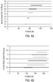
- the data of FIG. 4A represents the conventional separation technique utilizing a Gaussian infrared laser beam projected onto a transparent workpiece at a speed of 200 mm/s, where the beam diameter (i.e., the 1/e 2 diameter) is graphically depicted as a function of beam power sufficient for separation.
- FIG. 4B represents an annular infrared laser beam as described herein projected onto a transparent workpiece at a speed of 200 mm/s, where the outer beam diameter is graphically depicted as a function of suitable beam power. As can be seen in FIGS.
- the infrared beam power range which is suitable for separating the transparent workpiece is broader utilizing the annular beam rather than the Gaussian beam of the conventional process.
- the power of the infrared laser beam may be more widely varied using the annular beam profile, allowing for more flexibility in processing.
- the infrared laser beam may have a power of from about 20 W to about 1000 W, such as from about 50 W to about 300 W, or from about 75 W to about 200 W, and sub ranges of power and relative to outer diameter as depicted in FIG. 4B .
- separating a transparent workpiece 130 includes an initial step of forming a contour line 110 on the surface of the glass workpiece 130.
- the contour line 110 defines the intended line of separation and generally includes defects which, when further operated on such as by heating or the like, cause spontaneous separation of the transparent workpiece 130 along the contour line 110.
- an annular laser beam 210 from an infrared laser is directed onto the surface of the glass workpiece 130 along the contour line.
- the annular laser beam 210 may be formed by directing an initial Gaussian-shaped beam of, for example, a CO 2 laser through an axicon lens 310, a first plano-convex lens 312, and a second plano-convex lens 314 as depicted in FIG. 3 to facilitate shaping the Gaussian-shaped beam into a Bessel beam having a beam spot with an annular profile as depicted in FIG. 1 and an annular energy distribution as depicted in FIG. 2 .
- the resultant annular laser beam 210 has a profile which is generally circular symmetric (i.e., an annulus or ring).
- the annular laser beam 210 is positioned on the surface of the transparent workpiece 130 such that the contour line 110 generally bisects the annular laser beam 210. That is, the annular laser beam 210 is positioned on the surface of the transparent workpiece 130 such that the contour line 110 lies along a diameter of the annular laser beam 210.
- the annular laser beam 210 is then traversed over the contour line 110 by moving the annular laser beam 210 relative to the workpiece 130, moving the workpiece 130 relative to the annular laser beam 210, or moving the annular laser beam 210 and the workpiece 130 relative to one another.
- the annular laser beam 210 imparts thermal energy to the transparent workpiece 130 along the contour line 110.
- the maximum amount of thermal energy imparted to the transparent workpiece 130 is not directly on the contour line 110, but rather in areas of the transparent workpiece 130 laterally offset and spaced apart from the contour line 110 which mitigates unintended damage to the transparent workpiece 130 such as melting and/or laterally cracking.
- the annular laser beam 210 traverses the contour line 110, the annular laser beam 210 heats up the material of the transparent workpiece 130 causing expansion of the material. This results in the development of compressive stress in the heated areas while tensile stresses develop along the contour line 110 ahead of and behind the annular laser beam 210. These stresses cause the contour line 110 and, more specifically, the defects of the contour line 110 to spontaneously propagate both through the thickness of the transparent workpiece 130 and along the contour line 110 resulting in the spontaneous separation of the transparent workpiece 130 along the contour line 110.
- the present disclosure provides a process for precision cutting and/or separation of transparent workpieces such as, for example, glass workpieces formed from alkaline earth boro-aluminosilicate glass compositions, sapphire, fused silica, or combinations thereof.
- transparent workpieces such as, for example, glass workpieces formed from alkaline earth boro-aluminosilicate glass compositions, sapphire, fused silica, or combinations thereof.
- Such transparent workpieces may be utilized as display and/or TFT (thin film transistor) substrates.
- TFT thin film transistor
- Some examples of such glasses or glass compositions suitable for display or TFT use are EAGLE XG®, CONTEGO, and CORNING LOTUSTM available from Corning Incorporated of Corning, NY.
- the alkaline earth boro-aluminosilicate glass compositions may be formulated to be suitable for use as substrates for electronic applications including, without limitation, substrates for TFTs.
- the glass compositions used in conjunction with TFTs typically have coefficients of thermal expansion (CTE) similar to that of silicon (such as less than 5x10 -6 /K or even less than 4x10 -6 /K, for example, approximately 3 x10 -6 /K, or about 2.5x10 -6 /K to about 3.5 x10 -6 /K), and have low levels of alkali within the glass.
- CTE coefficients of thermal expansion
- Low levels of alkali may be used in TFT applications because alkali dopants, under some conditions, leach out of glass and contaminate or "poison" the TFTs, possibly rendering the TFTs inoperable.
- the laser cutting processes described herein may be used to separate transparent workpieces in a controlled fashion with negligible debris, minimum defects, and low subsurface damage to the edges, preserving workpiece integrity and strength.
- the contour line may comprise line defects (sometimes referred to herein as perforations) produced by interaction of the transparent workpiece with a pulsed laser beam, such as is described in U.S. Publication No. 2015/0360991 .
- This method utilizing a pulsed laser to form defects in the transparent workpiece may be well suited for materials that are transparent to the selected pulsed laser wavelength.
- This pulsed laser wavelength may be, for example, 1064 nm, 532 nm, 355 nm, or 266 nm.
- Demonstrations of the method for forming the contour line of defects have been made, for example, by using EAGLE XG® compositions in thicknesses ranging from 0.025 mm to 0.7 mm.
- the pulsed laser beam may create multi-photon absorption (MPA) in substantially transparent materials such as glass workpieces.
- MPA is the simultaneous absorption of two or more photons of identical or different frequencies that excites a molecule from one state (usually the ground state) to a higher energy electronic state (i.e., ionization). The energy difference between the involved lower and upper states of the molecule is equal to the sum of the energies of the involved photons.
- MPA also called induced absorption, can be a second-order or third-order process (or higher order), for example, that is several orders of magnitude weaker than linear absorption. It differs from linear absorption in that the strength of second-order induced absorption may be proportional to the square of the light intensity, for example, and thus it is a nonlinear optical process.
- the perforation step that creates the contour line may utilize an ultra-short pulse laser in combination with optics that generate a focal line to fully perforate a transparent workpiece formed from, for example, various glass compositions.
- the pulse duration of the individual pulses is in a range of from about 1 picosecond to about 100 picoseconds, such as from about 5 picoseconds to about 20 picoseconds, and the repetition rate of the individual pulses may be in a range from about 1 kHz to 4 MHz, such as in a range from about 10 kHz to about 3 MHz, or from about 10 kHz to about 650 kHz.
- the pulses may be produced in bursts of two pulses or more (such as, for example, 3 pulses, 4 pulses, 5 pulses, 10 pulses, 15 pulses, 20 pulses, or more per pulse burst, such as from 1 to 30 pulses per pulse burst, or from 5 to 20 pulses per pulse burst).
- the pulses within the burst may be separated by a duration that is in a range from about 1 nsec to about 50 nsec, for example, from about 10 nsec to about 30 nsec, such as about 20 nsec.
- the burst repetition frequency may be in a range of from about 1 kHz to about 2 MHz, such as from about 1 kHz to about 200 kHz.
- Bursting or producing pulse bursts is a type of laser operation where the emission of pulses is not in a uniform and steady stream but rather in tight clusters of pulses.
- the pulse burst laser beam may have a wavelength selected based on the material of the transparent workpiece being operated on such that the material of the transparent workpiece is substantially transparent at the wavelength.
- the average laser power per burst measured at the material may be at least about 40 ⁇ J per mm of thickness of material.
- the average laser power per burst may be from about 40 ⁇ J/mm to about 2500 ⁇ J/mm, or from about 500 ⁇ J/mm to about 2250 ⁇ J/mm.
- pulse bursts of from about 300 ⁇ J to about 600 ⁇ J may cut and/or separate the workpiece, which corresponds to an exemplary range of about 428 ⁇ J/mm to about 1200 ⁇ J/mm (i.e., 300 ⁇ J/0,7mm for 0.7 mm EAGLE XG® glass and 600 ⁇ J/0.5mm for a 0.5 mm EAGLE XG® glass).
- the transparent workpiece may be translated relative to the pulsed laser beam (or the pulsed laser beam may be translated relative to the glass) to create contour lines that trace out the shape of a desired part with defects.
- the pulsed laser may create hole-like defect zones, referred to herein as line defects, that may penetrate the full depth of the glass. It should be understood that while sometimes described as “holes” or “hole-like,” the defects disclosed herein may generally not be void spaces, but are rather portions of the workpiece which has been modified by laser processing as described herein. In display or TFT type glasses these line defects may generally be spaced apart from one another by a distance of from about 5 microns to about 20 microns.
- suitable spacing between the line defects may be from about 1 microns to about 30 microns, such as from about 5 microns to about 15 microns, from about 5 microns to about 12 microns, from about 7 microns to about 15 microns, or from about 7 microns to about 12 microns for the TFT/display glass compositions).
- the internal diameter of a line defect is the internal diameter of the modified area defining the line defect in the transparent workpiece.
- the internal diameter of the line defect may be less than or equal to about 1 micron, for example, less than or equal to about 500 nm, less than or equal to about 400 nm, or even less than or equal to about 300 nm.
- the internal diameter of a line defects may be as large as the spot diameter of the laser beam focal line.
- the pulsed laser beam focal line may have an average spot diameter in a range of from about 0.1 micron to about 30 microns, such as from about 0.1 microns to about 10 microns, from about 0.1 microns to about 5 microns, for example, from about 1.5 microns to about 3.5 microns.
- the line defects may potentially still be observable at the separated surface and may have a width comparable to the internal diameters of the line defects.
- widths of line defects on a cut surface of a workpiece prepared by embodiments of methods described herein may have widths of from about 0.1 micron to about 5 microns.
- the process may also be used to perforate stacks of transparent workpieces, such as stacks of sheets of glass, and may fully perforate glass stacks of up to a few mm total height with a single laser pass.
- the glass stacks additionally may have air gaps in various locations.
- ductile layers such as adhesives may be disposed between the glass stacks.
- the pulsed laser process will still, in a single pass, fully perforate both the upper and lower glass layers of such a stack.
- one of the enablers of the described perforation process is the high aspect ratio of the line defects created by the ultra-short pulsed laser.
- This high aspect ratio allows creation of a contour line that extends, in some embodiments, from the top to the bottom surfaces of the workpiece to be cut.
- this line defect may be created by a single pulse and if necessary, additional pulses may be used to increase the extension of the affected area (depth and width).
- the pulsed laser beam focal line may have a length in a range of from about 0.1 mm to about 10 mm, or from about 0.5 mm to about 5 mm, for example, about 1 mm, about 2 mm, about 3 mm, about 4 mm, about 5 mm, about 6 mm, about 7 mm, about 8 mm, or about 9 mm, or a length in a range of from about 0.1 mm to about 2 mm, or from 0.1 mm to about 1 mm.
- the pulsed laser beam focal line may have an average spot diameter in a range of from about 0.1 micron to about 5 microns.
- the line defects each may have a diameter of from about 0.1 microns to 30 microns, for example, from about 0.25 microns to about 5 microns (e.g., from about 0.25 microns to about 0.75 microns).
- the generation of a focal line may be performed by sending a Gaussian laser beam into an axicon lens, in which case a beam profile known as a Gauss-Bessel beam is created.
- a beam profile known as a Gauss-Bessel beam is created.
- Such a beam diffracts much more slowly (e.g., the beam may maintain single micron diameter spot sizes for ranges of hundreds of microns or millimeters as opposed to a few tens of microns or less) than a Gaussian beam.
- the depth of focus or length of intense interaction with the material may be much larger than when using a Gaussian beam only.
- Other forms of slowly diffracting or non-diffracting beams may also be used, such as Airy beams.
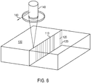
- a contour line 110 comprising a plurality of line defects 120 may be formed by processing the transparent workpiece 130 with an ultra-short pulsed laser beam 140 moving in processing direction 160.
- the line defects 120 may extend, for example, through the thickness of the transparent workpiece 130, and may be orthogonal to the major (flat) surfaces of the transparent workpiece 130.
- contour lines may be linear, like the contour line 110 illustrated in FIG. 6 , the contours lines may also be nonlinear (i.e., having a curvature). Curved contour lines may be produced, for example, by translating either the transparent workpiece 130 or pulsed laser beam 140 with respect to the other in two dimensions instead of one dimension.
- a heat treatment e.g., with an infrared laser
- a plurality of line defects 120 may define the contour line 110.
- the distance, or periodicity, between adjacent line defects 120 along the direction of the contour lines 110 may be at least about 0.1 micron or 1 micron and less than or equal to about 20 microns or even 30 microns.
- the periodicity between adjacent line defects 120 may be from about 0.5 to about 15 microns, or from about 3 microns to about 10 microns, or from about 0.5 microns to about 3.0 microns.
- the periodicity between adjacent line defects 120 may be from about 0.5 micron to about 1.0 micron.
- the periodicity between adjacent line defects 120 may be at least about 1 microns, such as at least about 5 microns, or from about 1 microns to about 15 microns.
- the optical method of forming the focal line may take multiple forms, using donut shaped laser beams and spherical lenses, axicon lenses, diffractive elements, or other methods to form the linear region of high intensity.
- the type of laser (picosecond, femtosecond, etc.) and wavelength (infrared, green, UV, etc.) may also be varied, as long as sufficient optical intensities are reached to create breakdown of the workpiece material in the region of focus on the transparent workpiece through nonlinear optical effects.
- the laser may be a pulse burst laser which allows for control of the energy deposition with time by adjusting the number of pulses within a given burst.
- an ultra-short pulsed laser may be used to create a high aspect ratio vertical line defect in a consistent, controllable, and repeatable manner.
- optical techniques are used to create a line focus of a high intensity laser beam within a transparent workpiece.
- an axicon lens element is used in an optical lens assembly to create a region of high aspect ratio, taper-free line defects using ultra-short (picoseconds or femtosecond duration) Bessel beams.
- the axicon condenses the laser beam into a high intensity region of cylindrical shape and high aspect ratio (long length and small diameter).
- a method for forming a perforated contour line may include focusing a pulsed laser beam 2 from a laser apparatus 3 into a laser beam focal line 2b oriented along the beam propagation direction.
- a laser (not shown) emits laser beam 2, which has a portion 2a incident to the optical assembly 6.
- the optical assembly 6 turns the incident laser beam into an extensive laser beam focal line 2b on the output side over a defined expansion range along the beam direction (length 1 of the focal line).
- the planar workpiece 1 is positioned in the beam path to at least partially overlap the laser beam focal line 2b of pulsed laser beam 2.
- the laser beam focal line is thus directed into the workpiece 1.
- Reference 1a designates the surface of the planar workpiece 1 facing the optical assembly 6 or the laser, respectively, and reference 1b designates the reverse surface of workpiece 1.
- the workpiece 1 has a depth d measured perpendicularly to the planar surfaces 1a and 1b, i.e., to the workpiece plane.
- the workpiece 1 is aligned perpendicular to the longitudinal beam axis and thus behind the same focal line 2b produced by the optical assembly 6 (the workpiece 1 is perpendicular to the plane of the drawing).
- the focal line 2b being oriented or aligned along the beam direction, the workpiece 1 is positioned relative to the focal line 2b such that the focal line 2b starts before the surface 1a of the workpiece 1 and stops before the surface 1b of the workpiece 1 (i.e., focal line 2b terminates within the workpiece 1 and does not extend beyond surface 1b).
- the extensive laser beam focal line 2b In the overlapping area of the laser beam focal line 2b with workpiece 1 (i.e., in the workpiece material covered by focal line 2b), the extensive laser beam focal line 2b generates (assuming suitable laser intensity along the laser beam focal line 2b, which intensity is ensured by the focusing of pulsed laser beam 2 on a section of length 1, i.e. a line focus of length 1) an extensive section 2c (aligned along the longitudinal beam direction) along which an induced absorption is generated in the workpiece material. The induced absorption produces a line defect formation in the workpiece material along section 2c.
- the line defect is a microscopic (e.g., having an internal diameter of from about 100 nm to about 0.5 microns) elongated defect in the workpiece which may be generated by using a single high energy burst of multiple laser pulses.
- a series of these line defects creates a perforation pattern in the transparent workpiece along the contour line.
- individual line defects may be created at rates of several hundred kilohertz (i.e., several hundred thousand line defects per second). With relative motion between the focal line 2b and the transparent workpiece 1, these line defects may be placed adjacent to one another (spatial separation varying from sub-micron to many microns as desired).
- the line defect is a "through defect", which is a defect that extends from top surface 1a to bottom surface 1b.
- the line defect formation is not only local, but over the entire length of the extensive section 2c of the induced absorption.
- the length of section 2c (which corresponds to the length of the overlapping of laser beam focal line 2b with workpiece 1) is labeled with reference L.
- the internal diameter of the defect area (i.e., the defect) at the section 2c of the induced absorption is labeled with reference D.
- This internal diameter D basically corresponds to the average diameter ⁇ of the laser beam focal line 2b, that is, an average spot diameter in a range of between about 0.1 micron and about 5 microns.
- optical assemblies 6, which may be applied to generate the focal line 2b, as well as a representative optical setup, in which these optical assemblies may be applied, are described below. All assemblies or setups are based on the description above so that identical references are used for identical components or features or those which are equal in their function. Therefore only the differences are described below.
- the portion 2a of the laser beam emitted by laser apparatus 3 incident to the optical assembly 6 is first directed onto a circular aperture 8 which is opaque to the wavelength of laser radiation used.
- Aperture 8 is oriented perpendicular to the longitudinal beam axis and is centered on the central portion of the depicted beam portion 2a.
- the diameter of aperture 8 is selected in such a way that the laser radiation near the center of beam portion 2a (i.e., the central beam portion, here labeled with 2aZ) hit the aperture and is completely absorbed by it.
- marginal rays here labeled with 2aR
- the circular aperture 8 Only the beams in the outer perimeter range of beam portion 2a (i.e., marginal rays, here labeled with 2aR) are not absorbed by the circular aperture 8 due to the reduced aperture size compared to the beam diameter, and pass aperture 8 laterally and hit the marginal areas of the focusing lens 7 of the optical assembly 6, which, in this embodiment, is designed as a spherically cut, bi-convex lens.
- the laser beam focal line 2b may not only be a single focal point for the laser beam, but rather a series of focal points for different rays in the laser beam.
- the series of focal points form an elongated focal line of a defined length, shown in FIG. 8A as the length 1 of the laser beam focal line 2b.
- Lens 7 may be centered on the central beam and may be designed as a non-corrected, bi-convex focusing lens in the form of a common, spherically cut lens.
- aspheres or multi-lens systems deviating from ideally corrected systems which do not form an ideal focal point but a distinct, elongated focal line of a defined length, may also be used (i.e., lenses or systems which do not have a single focal point).
- the zones of the lens thus focus along a focal line 2b, subject to the distance from the lens center.
- the diameter of aperture 8 across the beam direction may be approximately 90% of the diameter of the beam portion 2a (defined by the distance required for the intensity of the beam to decrease to 1/e 2 of the peak intensity) and approximately 75% of the diameter of the lens 7 of the optical assembly 6.
- FIG. 8A shows a section in one plane through the central beam, and the complete three-dimensional bundle may be seen when the depicted beams are rotated around the focal line 2b.
- FIG. 8B-1 through FIG. 8B-4 show (not only for the optical assembly in FIG. 8A , but also for any other applicable optical assembly 6) that the position of laser beam focal line 2b may be controlled by suitably positioning and/or aligning the optical assembly 6 relative to workpiece 1 as well as by suitably selecting the parameters of the optical assembly 6.
- the length 1 of the focal line 2b may be adjusted in such a way that it exceeds the workpiece depth d (here by factor 2). If workpiece 1 is placed (viewed in longitudinal beam direction) centrally to focal line 2b, an extensive section of induced absorption 2c may be generated over the entire workpiece thickness.
- the laser beam focal line 2b may have a length 1 in a range of from about 0.01 mm to about 100 mm or in a range of from about 0.1 mm to about 10 mm.
- Various embodiments may be configured to have a focal line 2b with a length 1 of about 0.1 mm, about 0.2 mm, about 0.3 mm, about 0.4 mm, about 0.5 mm, about 0.7 mm, about 1 mm, about 2 mm, about 3 mm, about 4 mm, or about 5 mm e.g., from about 0.5 mm to about 5 mm
- FIG. 8B-2 a focal line 2b of length 1 is generated which generally corresponds to the workpiece depth d. Since workpiece 1 is positioned relative to focal line 2b in such a way that focal line 2b starts at a point outside the workpiece 1, the length 1 of the extensive section of induced absorption 2c (which extends from the workpiece surface to a defined workpiece depth, but not to the reverse surface 1b) is smaller than the length 1 of focal line 2b.
- FIG. 8B-3 shows the case in which the workpiece 1 (viewed along a direction perpendicular to the beam direction) is positioned above the starting point of focal line 2b so that, as in FIG.
- the length 1 of focal line 2b is greater than the length 1 of the section of induced absorption 2c in workpiece 1.
- the focal line thus starts within the workpiece and extends beyond the reverse surface 1b.
- the focal line 2b may be particularly advantageous to position the focal line 2b in such a way that at least one of surfaces 1a, 1b is covered by the focal line (e.g. the setup of FIG. 8B-2 or FIG. 8B-3 ), so that the section 2c of induced absorption starts at least on one surface of the workpiece. In this way it is possible to achieve virtually ideal cuts while avoiding ablation, feathering, and particulation at the surface.
- FIG. 9 depicts another embodiment of an optical assembly 6.
- the basic construction follows the one described in FIG. 8A so that only the differences are described below.
- the depicted optical assembly in FIG. 9 utilizes optics with a non-spherical free surface in order to generate the focal line 2b, which is shaped in such a way that a focal line of defined length 1 is formed.
- aspheres may be used as optic elements of the optical assembly 6.
- a so-called conical prism, also referred to as axicon is used.
- An axicon is a conically cut lens which forms a spot source on a line along the optical axis (or transforms a laser beam into a ring).
- the cone angle of the axicon in the example is approximately 10°. However, it should be understood that other ranges of the axicon cone angle may also be utilized.
- the apex of the axicon 9 is directed towards the incidence direction and centered on the beam center. Since the focal line 2b produced by the axicon 9 starts within the interior of the axicon, workpiece 1 (here aligned perpendicularly to the main beam axis) may be positioned in the beam path directly behind axicon 9. As FIG. 9 shows, it is also possible to shift workpiece 1 along the beam direction due to the optical characteristics of the axicon while remaining within the range of focal line 2b. The section of the induced absorption 2c in the material of workpiece 1 therefore extends over the entire workpiece depth d.
- the depicted layout may be subject to the following restrictions: since the region of focal line 2b formed by axicon 9 begins within axicon 9, a significant part of the laser energy is not focused into the section of induced absorption 2c of focal line 2b, which is located within the material, in the situation where there is a separation between axicon 9 and the workpiece. Furthermore, length 1 of focal line 2b is related to the beam diameter through the refractive indices and cone angles of axicon 9. This is why, in the case of relatively thin materials (e.g., several millimeters), the total focal line is much longer than the thickness of the workpiece, having the effect that much of the laser energy is not focused in the thickness of the material.
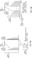
- FIG. 10A depicts such an optical assembly 6 in which a first optical element with a non-spherical free surface designed to form an extensive laser beam focal line 2b is positioned in the beam path from laser apparatus 3.
- this first optical element is an axicon 10 with a cone angle of 5° positioned perpendicularly to the beam direction and centered on beam from laser apparatus 3.
- the apex of the axicon 10 is oriented towards the beam direction.
- a second, focusing optical element here the plano-convex lens 11 (the curvature of which is oriented towards the axicon), is positioned in the beam direction at a distance z1 from the axicon 10.
- the distance z1 may be approximately 300 mm and is selected such that the laser radiation formed by axicon 10 is circularly incident on the outer radial portion of lens 11.
- Lens 11 focuses the circular radiation on the output side at a distance Z2, in this case approximately 20 mm from lens 11, on a focal line 2b of a defined length, in this case 1.5 mm.
- the effective focal length of lens 11 is 25 mm in this embodiment.
- the circular transformation of the laser beam by axicon 10 is labeled with the reference SR.
- FIG. 10B depicts the formation of the focal line 2b or the induced absorption 2c in the material of workpiece 1 according to the optical assembly 6 of FIG. 10A .
- the optical characteristics of both elements 10, 11 as well as their positioning is selected such that the length 1 of the focal line 2b in the beam direction is the same as the depth d of workpiece 1.
- an exact positioning of workpiece 1 along the beam direction may be necessary in order to position the focal line 2b exactly between the two surfaces 1a and 1b of workpiece 1, as shown in FIG. 10B .
- a focusing meniscus lens or another higher-order corrected focusing lens e.g., an asphere, multi-lens system.
- both effects may be avoided by including another lens, a collimating lens 12, in the optical assembly 6.
- the additional collimating lens 12 serves to tightly adjust the circular illumination of focusing lens 11.
- the focal length f of collimating lens 12 is selected such that the desired circle diameter dr results from the distance zla from the axicon to the collimating lens 12, which is equal to f'.
- the desired width br of the ring may be adjusted via the distance zlb between the collimating lens 12 and the focusing lens 11. As a matter of pure geometry, the small width of the circular illumination leads to a short focal line. A minimum may be achieved at distance f'.
- the optical assembly 6 depicted in FIG. 11 is thus based on the one depicted in FIG. 10A so that only the differences are described below.
- the collimating lens 12, here also designed as a plano-convex lens with its curvature towards the beam direction is placed centrally in the beam path between axicon 10 (with its apex towards the beam direction) on one side and the plano-convex lens 11 on the other side.
- the distance between the collimating lens 12 from axicon 10 is referred to as zla
- the distance between the focusing lens 11 from collimating lens 12 is zlb
- the distance of the focal line 2b from the focusing lens 11 is z2.
- a very short focal line 2b is intended to be generated so that the circle width br of approximately 4 mm at lens 12 is reduced to approximately 0.5 mm at lens 11 due to the focusing properties of lens 12 (circle diameter dr is 22 mm in the example).
- FIGS. 12A-12C illustrate the laser-matter interaction at different laser intensity regimes.
- the unfocused pulsed laser beam 710 goes through a transparent workpiece 720 without introducing any modification to the workpiece 720.
- the nonlinear effect is not present because the laser energy density (or laser energy per unit area illuminated by the beam) is below the threshold necessary to induce nonlinear effects.
- the higher the energy density the higher the intensity of the electromagnetic field. Therefore, as shown in FIG.
- the diffraction pattern of an axicon lens 750 creates interference that generates a Bessel-shaped intensity distribution (i.e., the high intensity cylinder 760) and only in that volume is the intensity sufficient to create nonlinear absorption and modification of the material 720.
- the diameter of cylinder 760 in which the Bessel-shaped intensity distribution is sufficient to create nonlinear absorption and modification to the material is also the spot diameter of the laser beam focal line.
- a picosecond pulsed laser e.g., a 1064 nm, or 532 nm picosecond pulsed laser
- a picosecond pulsed laser which produces bursts of multiple pulses in combination with line-focus beam forming optics may be used to line defects in the glass composition.
- other pulsed lasers may also be utilized in the perforation processes described herein.
- a display/TFT glass composition with a thickness of up to 0.7 mm may be positioned so that it is within the region of the focal line produced by the optics.
- a focal line of about 1 mm in length a 1064 nm picosecond laser that produces output power of about 24 W or more at a burst repetition rate of 200 kHz (about 120 ⁇ J/burst or more) measured at the transparent workpiece, the optical intensities in the focal line region may be sufficient to create non-linear absorption in the glass composition.
- the pulsed laser beam may have an average laser burst energy measured, at the material, greater than 40 ⁇ J per mm of thickness of the workpiece.
- the average laser burst energy utilized may be as great as 2500 ⁇ J per mm of thickness of the material, for example from about 40 ⁇ J/mm to about 2500 ⁇ J/mm, from about 400 ⁇ J/mm to about 1300 ⁇ J/mm, or from about 550 ⁇ J/mm to about 1000 ⁇ J/mm, because the energy density is sufficient to make a thorough damage track of line defects in the workpiece while minimizing the extent of micro cracking orthogonal to the perforated line or cut edge.
- This "average pulse burst laser energy" per mm may also be referred to as an average per-burst linear energy density, or an average energy per laser pulse burst per mm of thickness of the material.
- a region of damaged, ablated, vaporized, or otherwise modified material within the glass composition may be created that approximately follows the linear region of high optical intensity created by the laser beam focal line.
- Each burst 500 contains multiple individual pulses 500A (such as at least two pulses, at least 5 pulses, at least 7 pulses, at least 8 pulses, at least 9 pulses, at least 10 pulses, at least 15 pulses, at least 20 pulses, or even more pulses) of very short duration. That is, a burst is a group of pulses, and the bursts are separated from one another by a longer duration than the separation of individual adjacent pulses within each burst.
- the number of pulses per burst may be from about 1 to 30 (such as from 5 to 20).
- Pulses 500A have pulse duration T d of up to 100 psec (for example, 0.1 psec, 5 psec, 10 psec, 15 psec, 18 psec, 20 psec, 22 psec, 25 psec, 30 psec, 50 psec, 75 psec, or any range therebetween).
- the energy or intensity of each individual pulse 500A within the burst may not be equal to that of other pulses within the burst, and the intensity distribution of the multiple pulses within a burst 500 often follows an exponential decay in time governed by the laser design.
- each pulse 500A within the burst 500 of the exemplary embodiments described herein is separated in time from the subsequent pulse in the burst by a duration T p of from about 1 nsec to about 50 nsec (e.g., from about 10 nsec to about 50 nsec, or from about 10 nsec to about 30 nsec, with the time often governed by the laser cavity design).
- T p the time separation between adjacent pulses within a burst 500 may be relatively uniform (e.g., within about 10% of one another).
- each pulse within a burst is separated in time from the subsequent pulse by approximately 20 nsec (50 MHz).
- the pulse to pulse separation T p within a burst is maintained within about ⁇ 10%, or about ⁇ 2 nsec.
- the time between each burst of pulses i.e., the time separation T b between bursts
- the time between each burst of pulses may be from about 0.25 microseconds to about 1000 microseconds, e.g., from about 1 microsecond to about 10 microseconds, or from about 3 microseconds to about 8 microseconds.
- the time separation T b is about 5 microseconds for a laser with a burst repetition rate of about 200 kHz.
- the laser burst repetition rate may be in a range of from about 1 kHz to about 4 MHz.
- the laser burst repetition rates may be, for example, in a range of from about 10 kHz to 650 kHz.
- the time T b between the first pulse in each burst to the first pulse in the subsequent burst may be from about 0.25 microsecond (4 MHz burst repetition rate) to about 1000 microseconds (1 kHz burst repetition rate), for example from about 0.5 microseconds (2 MHz burst repetition rate) to about 40 microseconds (25 kHz burst repetition rate), or from about 2 microseconds (500 kHz burst repetition rate) to about 20 microseconds (50k Hz burst repetition rate).
- the exact timing, pulse duration, and burst repetition rate may vary depending on the laser design, but short pulses (T d ⁇ 20 psec and preferably T d ⁇ 15 psec) of high intensity have been shown to work particularly well.
- the energy required to modify the material may be described in terms of the burst energy (i.e., the energy contained within a burst where each burst 500 contains a series of pulses 500A), or in terms of the energy contained within a single laser pulse (many of which may comprise a burst).
- the energy per burst may be from about 25 ⁇ J to about 750 ⁇ J, e.g., from about 50 ⁇ J to about 500 ⁇ J, or from about 50 ⁇ J to about 250 ⁇ J.
- the energy per burst may be from about 100 ⁇ J to about 250 ⁇ J.
- the energy per burst may be higher (e.g., from about 300 ⁇ J to about 500 ⁇ J, or from about 400 ⁇ J to about 600 ⁇ J, depending on the specific display/TFT glass composition of the workpiece).
- the energy of an individual pulse within the burst will be less, and the exact individual laser pulse energy will depend on the number of pulses 500A within the burst 500 and the rate of decay (e.g., exponential decay rate) of the laser pulses with time as shown in FIGS. 13A and 13B .
- the rate of decay e.g., exponential decay rate
- a pulsed laser beam capable of generating such bursts is advantageous for cutting or modifying transparent materials, for example glass.
- the use of a burst sequence that spreads the laser energy over a rapid sequence of pulses within the burst 500 allows access to larger timescales of high intensity interaction with the material than is possible with single-pulse lasers. While a single-pulse may be expanded in time, the intensity within the pulse is reduced as roughly one over the pulse width. Therefore, if a 10 psec single pulse is expanded to a 10 nsec pulse, the intensity is reduced by roughly three orders of magnitude.
- the intensity during each pulse 500A within the burst 500 may remain relevantly high (for example, three 10 psec pulses 500A spaced apart in time by approximately 10 nsec still allows the energy within each pulse burst to be approximately three times higher than that of a single 10 psec pulse) and the laser interacts with the material over a timescale that is three orders of magnitude larger.
- the required amount of burst energy to modify the material will depend on the workpiece material composition and the length of the line focus used to interact with the workpiece. The longer the interaction region, the more the energy is spread out, and higher burst energy will be required.
- Timing, pulse duration, and burst repetition rates may vary depending on the laser design, but short pulses times (e.g., less than about 15 psec, or even less than or equal to about 10 psec) of high intensity pulses may be exemplary in some embodiments.
- a defect is formed in the material when a single burst of pulses strikes essentially the same location on the transparent workpiece. That is, multiple laser pulses within a single burst correspond to a single line defect in the transparent workpiece. Since the workpiece is translated (e.g., by a constantly moving stage or the beam moved relative to the workpiece), the individual pulses within the burst cannot be at exactly the same spatial location on the glass.
- the individual pulses may be within 1 ⁇ m of one another (i.e., they effectively strike the glass at essentially the same location).
- the pulses may strike the glass at a spacing, sp, from one another where 0 ⁇ sp ⁇ 500 nm.
- sp spacing
- the individual pulses within the burst strike the glass within 250 nm of each other.
- pulse burst energy may be from about 100 ⁇ J to about 600 ⁇ J per burst, such as from about 300 ⁇ J to about 600 ⁇ J per burst. Working outside this range may result in successful separation of other glasses, but not display (or TFT) glass compositions.
- the pulse burst energy may be from about 300 ⁇ J to about 500 ⁇ J, or for other display type glass from about 400 ⁇ J to about 600 ⁇ J.
- a pulse burst energy of 400 ⁇ J to 500 ⁇ J may work well for many display type glass compositions. Energy density within the line focus may be optimized for specific display or TFT glasses.
- a suitable range for the pulse burst energy may be from about 300 to about 500 ⁇ J and the line focus may be from about 1.0 mm to about 1.4 mm (where the line focus length is determined by the optical configuration).
- relatively low pulsed laser energy densities may form perforations which do not form as desired, causing the fracture between defects to not readily materialize during infrared laser processing, leading to increased break resistance (also referred to herein as a break strength) in display glass.
- the energy density of the pulsed laser beam is too high (e.g., greater than or equal to 600 ⁇ J, or even greater than 500 ⁇ J) the heat damage may be greater, causing the crack connecting the perforation to stray and not form along the desired path and the break resistance (break strength) of the display (or TFT) glass to dramatically increase.
- laser separation by infrared laser beam may be enhanced by utilizing an infrared laser beam which projects maximum intensity over the areas adjacent a contour line containing defects rather than directly onto the contour line.
- an annular beam profile may be utilized to achieve this infrared laser maximum power projection adjacent the contour line.
- Ranges can be expressed herein as from “about” one particular value, and/or to "about” another particular value. When such a range is expressed, another embodiment includes from the one particular value and/or to the other particular value. Similarly, when values are expressed as approximations, by use of the antecedent "about,” it will be understood that the particular value forms another embodiment. It will be further understood that the endpoints of each of the ranges are significant both in relation to the other endpoint, and independently of the other endpoint.
Landscapes
- Physics & Mathematics (AREA)
- Optics & Photonics (AREA)
- Engineering & Computer Science (AREA)
- Plasma & Fusion (AREA)
- Mechanical Engineering (AREA)
- Chemical & Material Sciences (AREA)
- Materials Engineering (AREA)
- Organic Chemistry (AREA)
- General Chemical & Material Sciences (AREA)
- Oil, Petroleum & Natural Gas (AREA)
- Chemical Kinetics & Catalysis (AREA)
- Health & Medical Sciences (AREA)
- Toxicology (AREA)
- Thermal Sciences (AREA)
- Laser Beam Processing (AREA)
- Re-Forming, After-Treatment, Cutting And Transporting Of Glass Products (AREA)
Claims (15)
- Procédé permettant le traitement au laser d'une pièce à travailler, le procédé comprenant :la formation d'une ligne de contour dans la pièce à travailler, la ligne de contour comprenant des défauts dans la pièce à travailler ; etl'orientation d'un faisceau laser infrarouge sur la pièce à travailler le long ou près de la ligne de contour pour séparer la pièce à travailler le long de la ligne de contour, ledit faisceau laser infrarouge possédant un profil de faisceau annulaire de sorte qu'une plus grande distribution d'énergie cumulée à partir du faisceau laser infrarouge soit située dans des zones adjacentes à la ligne de contour plutôt que directement sur la ligne de contour.
- Procédé selon la revendication 1, un diamètre externe du profil de faisceau annulaire allant d'environ 0,5 mm à environ 20 mm.
- Procédé selon la revendication 2, un diamètre interne du profil de faisceau annulaire allant d'environ 5 % à environ 95 % du diamètre de faisceau externe.
- Procédé selon l'une quelconque des revendications 1 à 3, une plus grande distribution d'énergie cumulée du faisceau laser infrarouge étant située dans des zones adjacentes à la ligne de contour des deux côtés de la ligne de contour plutôt que directement sur la ligne de contour.
- Procédé selon l'une quelconque des revendications 1 à 4, ledit faisceau laser infrarouge étant centré sur la ligne de contour.
- Procédé selon l'une quelconque des revendications 1 à 5, ledit faisceau laser infrarouge étant produit par un laser au dioxyde de carbone, un laser au monoxyde de carbone, un laser à l'état solide, une diode laser ou des combinaisons de ceux-ci.
- Procédé selon l'une quelconque des revendications 1 à 6, ladite formation de la ligne de contour comprenant : la focalisation d'un faisceau laser pulsé dans une ligne focale de faisceau laser pulsé orientée le long d'une direction de propagation de faisceau et dirigée dans la pièce à travailler, la ligne focale de faisceau laser pulsé générant une absorption induite à l'intérieur de la pièce à travailler, et l'absorption induite produisant un défaut de ligne le long de la ligne focale de faisceau laser pulsé à l'intérieur de la pièce à travailler ;
la translation de la pièce à travailler et de la ligne focale de faisceau laser pulsé l'une par rapport à l'autre le long de la ligne de contour, formant ainsi au laser une pluralité de défauts de ligne le long de la ligne de contour à l'intérieur de la pièce à travailler, un espacement entre les défauts de ligne adjacents allant de 1 micron à 30 microns ; et ledit laser pulsé produit des salves d'impulsions allant d'environ 1 impulsion par salve d'impulsions à environ 30 impulsions par salve d'impulsions et ladite énergie de salve d'impulsions allant d'environ 100 µJ à environ 600 µJ par salve d'impulsions. - Procédé selon la revendication 6, ledit faisceau laser pulsé produisant des salves d'impulsions allant d'environ 9 impulsions par salve d'impulsions à environ 20 impulsions par salve d'impulsions, et ladite énergie de salve d'impulsions allant d'environ 300 µJ par salve d'impulsions à environ 500 µJ par salve d'impulsions.
- Procédé selon la revendication 6,
ledit espacement entre les défauts de ligne adjacents allant d'environ 7 microns à environ 12 microns ;
et
ledit faisceau laser pulsé produisant des salves d'impulsions allant d'environ 5 impulsions par salve d'impulsions à environ 15 impulsions par salve d'impulsions, et ladite énergie de salve d'impulsions allant d'environ 400 µJ par salve d'impulsions à environ 600 microjoules par salve d'impulsions. - Procédé selon l'une quelconque des revendications 6 à 9, lesdites impulsions des salves d'impulsions possédant une durée allant d'environ 1 picoseconde à environ 100 picosecondes.
- Procédé selon l'une quelconque des revendications 6 à 10, lesdites salves d'impulsions possédant une fréquence de répétition comprise dans une plage allant d'environ 10 kHz à environ 3 MHz.
- Procédé selon l'une quelconque des revendications 6 à 11, ladite ligne focale du faisceau laser pulsé possédant un diamètre moyen de point compris dans une plage allant d'environ 0,1 micron à environ 10 microns.
- Procédé permettant le traitement au laser d'une pièce à travailler, le procédé comprenant :la focalisation d'un faisceau laser pulsé dans une ligne focale de faisceau laser pulsé dirigée dans la pièce à travailler, la ligne focale de faisceau laser pulsé produisant un défaut de ligne à l'intérieur de la pièce à travailler ; etla translation de la pièce à travailler et de la ligne focale de faisceau laser pulsé l'une par rapport à l'autre, formant ainsi au laser une pluralité de défauts de ligne le long d'une ligne de contour à l'intérieur de la pièce à travailler, un espacement entre les défauts de ligne adjacents allant de 5 microns à 15 microns ; etl'orientation d'un faisceau laser infrarouge sur la pièce à travailler le long ou près de la ligne de contour pour séparer la pièce à travailler le long de la ligne de contour, ledit faisceau laser infrarouge possédant un profil de faisceau de sorte qu'une plus grande distribution de l'énergie cumulée du faisceau laser infrarouge soit située dans des zones adjacentes à la ligne de contour des deux côtés de la ligne de contour plutôt que directement sur la ligne de contour.
- Procédé selon la revendication 13, ledit faisceau laser infrarouge possédant un profil de faisceau annulaire et étant centré sur la ligne de contour.
- Procédé selon la revendication 14, ledit faisceau laser infrarouge étant produit par un laser au dioxyde de carbone, un laser au monoxyde de carbone, un laser à l'état solide, une diode laser ou des combinaisons de ceux-ci.
Applications Claiming Priority (2)
| Application Number | Priority Date | Filing Date | Title |
|---|---|---|---|
| US201662368571P | 2016-07-29 | 2016-07-29 | |
| PCT/US2017/043437 WO2018022476A1 (fr) | 2016-07-29 | 2017-07-24 | Appareils et procédés de traitement laser |
Publications (2)
| Publication Number | Publication Date |
|---|---|
| EP3490945A1 EP3490945A1 (fr) | 2019-06-05 |
| EP3490945B1 true EP3490945B1 (fr) | 2020-10-14 |
Family
ID=59506385
Family Applications (1)
| Application Number | Title | Priority Date | Filing Date |
|---|---|---|---|
| EP17746612.5A Active EP3490945B1 (fr) | 2016-07-29 | 2017-07-24 | Procédés de traitement laser |
Country Status (6)
| Country | Link |
|---|---|
| US (1) | US10377658B2 (fr) |
| EP (1) | EP3490945B1 (fr) |
| JP (1) | JP7090594B2 (fr) |
| KR (1) | KR20190035805A (fr) |
| CN (1) | CN109803934A (fr) |
| WO (1) | WO2018022476A1 (fr) |
Cited By (1)
| Publication number | Priority date | Publication date | Assignee | Title |
|---|---|---|---|---|
| DE102021131812A1 (de) | 2021-12-02 | 2023-06-07 | Trumpf Laser- Und Systemtechnik Gmbh | Vorrichtung und Verfahren zum Trennen eines transparenten Werkstücks |
Families Citing this family (25)
| Publication number | Priority date | Publication date | Assignee | Title |
|---|---|---|---|---|
| EP2754524B1 (fr) | 2013-01-15 | 2015-11-25 | Corning Laser Technologies GmbH | Procédé et dispositif destinés au traitement basé sur laser de substrats plats, galette ou élément en verre, utilisant un faisceau laser en ligne |
| EP2781296B1 (fr) | 2013-03-21 | 2020-10-21 | Corning Laser Technologies GmbH | Dispositif et procédé de découpe de contours à partir de substrats plats au moyen d'un laser |
| US11556039B2 (en) | 2013-12-17 | 2023-01-17 | Corning Incorporated | Electrochromic coated glass articles and methods for laser processing the same |
| US10442719B2 (en) | 2013-12-17 | 2019-10-15 | Corning Incorporated | Edge chamfering methods |
| US9517963B2 (en) | 2013-12-17 | 2016-12-13 | Corning Incorporated | Method for rapid laser drilling of holes in glass and products made therefrom |
| EP3166895B1 (fr) | 2014-07-08 | 2021-11-24 | Corning Incorporated | Procédés et appareils pour traitement au laser de matériaux |
| JP2017530867A (ja) | 2014-07-14 | 2017-10-19 | コーニング インコーポレイテッド | 長さおよび直径の調節可能なレーザビーム焦線を用いて透明材料を加工するためのシステムおよび方法 |
| JP7292006B2 (ja) | 2015-03-24 | 2023-06-16 | コーニング インコーポレイテッド | ディスプレイガラス組成物のレーザ切断及び加工 |
| DE102015111490A1 (de) | 2015-07-15 | 2017-01-19 | Schott Ag | Verfahren und Vorrichtung zum lasergestützten Abtrennen eines Teilstücks von einem flächigen Glaselement |
| DE102016102768A1 (de) * | 2016-02-17 | 2017-08-17 | Schott Ag | Verfahren zur Kantenbearbeitung von Glaselementen und verfahrensgemäß bearbeitetes Glaselement |
| CN109641315B (zh) * | 2016-06-14 | 2021-12-31 | 艾维纳科技有限责任公司 | 多区段聚焦透镜以及用于晶圆切割或裁切之激光加工系统 |
| JP2019532908A (ja) * | 2016-08-30 | 2019-11-14 | コーニング インコーポレイテッド | 強度マッピング光学システムによる材料のレーザー切断 |
| JP6923284B2 (ja) | 2016-09-30 | 2021-08-18 | コーニング インコーポレイテッド | 非軸対称ビームスポットを用いて透明被加工物をレーザ加工するための装置及び方法 |
| LT3529214T (lt) | 2016-10-24 | 2021-02-25 | Corning Incorporated | Substrato apdorojimo stotis lakšto formos stiklo substratų lazeriniam mašininiam apdorojimui |
| KR20190104221A (ko) * | 2017-01-24 | 2019-09-06 | 코닝 인코포레이티드 | 광 섬유 및 이를 포함하는 광학 시스템 |
| US10906832B2 (en) * | 2017-08-11 | 2021-02-02 | Corning Incorporated | Apparatuses and methods for synchronous multi-laser processing of transparent workpieces |
| JP2020531392A (ja) * | 2017-08-25 | 2020-11-05 | コーニング インコーポレイテッド | アフォーカルビーム調整アセンブリを用いて透明被加工物をレーザ加工するための装置及び方法 |
| DE102018126381A1 (de) * | 2018-02-15 | 2019-08-22 | Schott Ag | Verfahren und Vorrichtung zum Einfügen einer Trennlinie in ein transparentes sprödbrüchiges Material, sowie verfahrensgemäß herstellbares, mit einer Trennlinie versehenes Element |
| US12011783B2 (en) * | 2018-05-25 | 2024-06-18 | Corning Incorporated | Scribing thin ceramic materials using beam focal line |
| US11059131B2 (en) | 2018-06-22 | 2021-07-13 | Corning Incorporated | Methods for laser processing a substrate stack having one or more transparent workpieces and a black matrix layer |
| DE102018220447A1 (de) | 2018-11-28 | 2020-05-28 | Trumpf Laser Gmbh | Verfahren zum Stoßschweißen mittels eines UKP-Laserstrahls sowie aus Einzelteilen zusammengefügtes optisches Element |
| CN110435160A (zh) * | 2019-09-09 | 2019-11-12 | 广东利元亨智能装备股份有限公司 | 一种激光焊接头及激光焊接方法 |
| CN112894146A (zh) * | 2019-12-04 | 2021-06-04 | 大族激光科技产业集团股份有限公司 | 玻璃基板通孔的激光加工方法和装置 |
| KR20230020498A (ko) * | 2020-06-04 | 2023-02-10 | 코닝 인코포레이티드 | 수정된 펄스 버스트 프로파일을 사용하여 투명 작업편을 레이저 처리하는 방법 |
| KR102189746B1 (ko) * | 2020-08-18 | 2020-12-11 | 국방과학연구소 | 도넛 형상의 빔을 이용한 광섬유 코팅 제거 장치 |
Family Cites Families (379)
| Publication number | Priority date | Publication date | Assignee | Title |
|---|---|---|---|---|
| US1790397A (en) | 1931-01-27 | Glass workins machine | ||
| US2682134A (en) | 1951-08-17 | 1954-06-29 | Corning Glass Works | Glass sheet containing translucent linear strips |
| US2749794A (en) | 1953-04-24 | 1956-06-12 | Corning Glass Works | Illuminating glassware and method of making it |
| GB1242172A (en) | 1968-02-23 | 1971-08-11 | Ford Motor Co | A process for chemically cutting glass |
| US3647410A (en) | 1969-09-09 | 1972-03-07 | Owens Illinois Inc | Glass ribbon machine blow head mechanism |
| US3775084A (en) | 1970-01-02 | 1973-11-27 | Owens Illinois Inc | Pressurizer apparatus for glass ribbon machine |
| US3729302A (en) | 1970-01-02 | 1973-04-24 | Owens Illinois Inc | Removal of glass article from ribbon forming machine by vibrating force |
| US3695498A (en) | 1970-08-26 | 1972-10-03 | Ppg Industries Inc | Non-contact thermal cutting |
| US3695497A (en) | 1970-08-26 | 1972-10-03 | Ppg Industries Inc | Method of severing glass |
| DE2231330A1 (de) | 1972-06-27 | 1974-01-10 | Agfa Gevaert Ag | Verfahren und vorrichtung zur erzeugung eines scharfen fokus |
| DE2757890C2 (de) | 1977-12-24 | 1981-10-15 | Fa. Karl Lutz, 6980 Wertheim | Verfahren und Vorrichtung zum Herstellen von Behältnissen aus Röhrenglas, insbesondere Ampullen |
| US4441008A (en) | 1981-09-14 | 1984-04-03 | Ford Motor Company | Method of drilling ultrafine channels through glass |
| US4546231A (en) | 1983-11-14 | 1985-10-08 | Group Ii Manufacturing Ltd. | Creation of a parting zone in a crystal structure |
| US4646308A (en) | 1985-09-30 | 1987-02-24 | Spectra-Physics, Inc. | Synchronously pumped dye laser using ultrashort pump pulses |
| JPS6318756A (ja) | 1986-07-09 | 1988-01-26 | Fujiwara Jiyouki Sangyo Kk | 生物育成、微生物培養工程における制御温度の監視方法及びその装置 |
| US4749400A (en) | 1986-12-12 | 1988-06-07 | Ppg Industries, Inc. | Discrete glass sheet cutting |
| DE3789858T2 (de) | 1986-12-18 | 1994-09-01 | Nippon Sheet Glass Co Ltd | Platten für Lichtkontrolle. |
| US4918751A (en) | 1987-10-05 | 1990-04-17 | The University Of Rochester | Method for optical pulse transmission through optical fibers which increases the pulse power handling capacity of the fibers |
| IL84255A (en) | 1987-10-23 | 1993-02-21 | Galram Technology Ind Ltd | Process for removal of post- baked photoresist layer |
| US4764930A (en) | 1988-01-27 | 1988-08-16 | Intelligent Surgical Lasers | Multiwavelength laser source |
| US4907586A (en) | 1988-03-31 | 1990-03-13 | Intelligent Surgical Lasers | Method for reshaping the eye |
| US4929065A (en) | 1988-11-03 | 1990-05-29 | Isotec Partners, Ltd. | Glass plate fusion for macro-gradient refractive index materials |
| US4891054A (en) | 1988-12-30 | 1990-01-02 | Ppg Industries, Inc. | Method for cutting hot glass |
| US5112722A (en) | 1989-04-12 | 1992-05-12 | Nippon Sheet Glass Co., Ltd. | Method of producing light control plate which induces scattering of light at different angles |
| US5104210A (en) | 1989-04-24 | 1992-04-14 | Monsanto Company | Light control films and method of making |
| US5035918A (en) | 1989-04-26 | 1991-07-30 | Amp Incorporated | Non-flammable and strippable plating resist and method of using same |
| US5040182A (en) | 1990-04-24 | 1991-08-13 | Coherent, Inc. | Mode-locked laser |
| ATE218904T1 (de) | 1991-11-06 | 2002-06-15 | Shui T Lai | Vorrichtung für hornhautchirurgie |
| US5265107A (en) | 1992-02-05 | 1993-11-23 | Bell Communications Research, Inc. | Broadband absorber having multiple quantum wells of different thicknesses |
| JPH05323110A (ja) | 1992-05-22 | 1993-12-07 | Hitachi Koki Co Ltd | 多ビーム発生素子 |
| US6016223A (en) | 1992-08-31 | 2000-01-18 | Canon Kabushiki Kaisha | Double bessel beam producing method and apparatus |
| CA2112843A1 (fr) | 1993-02-04 | 1994-08-05 | Richard C. Ujazdowski | Laser picoseconde a frequence de repetition variable |
| EP0656241B1 (fr) | 1993-06-04 | 1998-12-23 | Seiko Epson Corporation | Appareil et procede d'usinage au laser |
| US6489589B1 (en) | 1994-02-07 | 2002-12-03 | Board Of Regents, University Of Nebraska-Lincoln | Femtosecond laser utilization methods and apparatus and method for producing nanoparticles |
| US5436925A (en) | 1994-03-01 | 1995-07-25 | Hewlett-Packard Company | Colliding pulse mode-locked fiber ring laser using a semiconductor saturable absorber |
| US5400350A (en) | 1994-03-31 | 1995-03-21 | Imra America, Inc. | Method and apparatus for generating high energy ultrashort pulses |
| US5778016A (en) | 1994-04-01 | 1998-07-07 | Imra America, Inc. | Scanning temporal ultrafast delay methods and apparatuses therefor |
| JP2526806B2 (ja) | 1994-04-26 | 1996-08-21 | 日本電気株式会社 | 半導体レ―ザおよびその動作方法 |
| WO1995031023A1 (fr) | 1994-05-09 | 1995-11-16 | Massachusetts Institute Of Technology | Laser a dispersion compensee utilisant des extremites prismatiques |
| US5434875A (en) | 1994-08-24 | 1995-07-18 | Tamar Technology Co. | Low cost, high average power, high brightness solid state laser |
| US5776220A (en) | 1994-09-19 | 1998-07-07 | Corning Incorporated | Method and apparatus for breaking brittle materials |
| US5696782A (en) | 1995-05-19 | 1997-12-09 | Imra America, Inc. | High power fiber chirped pulse amplification systems based on cladding pumped rare-earth doped fibers |
| JPH09106243A (ja) | 1995-10-12 | 1997-04-22 | Dainippon Printing Co Ltd | ホログラムの複製方法 |
| US5736709A (en) | 1996-08-12 | 1998-04-07 | Armco Inc. | Descaling metal with a laser having a very short pulse width and high average power |
| US7353829B1 (en) | 1996-10-30 | 2008-04-08 | Provectus Devicetech, Inc. | Methods and apparatus for multi-photon photo-activation of therapeutic agents |
| KR100490317B1 (ko) | 1996-11-13 | 2005-05-17 | 코닝 인코포레이티드 | 내부적으로 채널화된 유리 제품의 제조방법 |
| US6156030A (en) | 1997-06-04 | 2000-12-05 | Y-Beam Technologies, Inc. | Method and apparatus for high precision variable rate material removal and modification |
| BE1011208A4 (fr) | 1997-06-11 | 1999-06-01 | Cuvelier Georges | Procede de decalottage de pieces en verre. |
| DE19728766C1 (de) | 1997-07-07 | 1998-12-17 | Schott Rohrglas Gmbh | Verwendung eines Verfahrens zur Herstellung einer Sollbruchstelle bei einem Glaskörper |
| JPH1179770A (ja) | 1997-07-10 | 1999-03-23 | Yamaha Corp | スクライブ装置及び劈開方法 |
| US6078599A (en) | 1997-07-22 | 2000-06-20 | Cymer, Inc. | Wavelength shift correction technique for a laser |
| JP3264224B2 (ja) | 1997-08-04 | 2002-03-11 | キヤノン株式会社 | 照明装置及びそれを用いた投影露光装置 |
| DE19750320C1 (de) | 1997-11-13 | 1999-04-01 | Max Planck Gesellschaft | Verfahren und Vorrichtung zur Lichtpulsverstärkung |
| WO1999029243A1 (fr) | 1997-12-05 | 1999-06-17 | Thermolase Corporation | Amelioration de l'aspect de la peau au moyen de la lumiere laser |
| US6501578B1 (en) | 1997-12-19 | 2002-12-31 | Electric Power Research Institute, Inc. | Apparatus and method for line of sight laser communications |
| JPH11197498A (ja) | 1998-01-13 | 1999-07-27 | Japan Science & Technology Corp | 無機材料内部の選択的改質方法及び内部が選択的に改質された無機材料 |
| US6272156B1 (en) | 1998-01-28 | 2001-08-07 | Coherent, Inc. | Apparatus for ultrashort pulse transportation and delivery |
| JPH11240730A (ja) | 1998-02-27 | 1999-09-07 | Nec Kansai Ltd | 脆性材料の割断方法 |
| JPH11269683A (ja) | 1998-03-18 | 1999-10-05 | Armco Inc | 金属表面から酸化物を除去する方法及び装置 |
| US6160835A (en) | 1998-03-20 | 2000-12-12 | Rocky Mountain Instrument Co. | Hand-held marker with dual output laser |
| DE69931690T2 (de) | 1998-04-08 | 2007-06-14 | Asml Netherlands B.V. | Lithographischer Apparat |
| US6256328B1 (en) | 1998-05-15 | 2001-07-03 | University Of Central Florida | Multiwavelength modelocked semiconductor diode laser |
| JPH11347758A (ja) | 1998-06-10 | 1999-12-21 | Mitsubishi Heavy Ind Ltd | 超精密加工装置 |
| JP4396953B2 (ja) | 1998-08-26 | 2010-01-13 | 三星電子株式会社 | レーザ切断装置および切断方法 |
| DE19851353C1 (de) | 1998-11-06 | 1999-10-07 | Schott Glas | Verfahren und Vorrichtung zum Schneiden eines Laminats aus einem sprödbrüchigen Werkstoff und einem Kunststoff |
| JP3178524B2 (ja) | 1998-11-26 | 2001-06-18 | 住友重機械工業株式会社 | レーザマーキング方法と装置及びマーキングされた部材 |
| US7649153B2 (en) | 1998-12-11 | 2010-01-19 | International Business Machines Corporation | Method for minimizing sample damage during the ablation of material using a focused ultrashort pulsed laser beam |
| US6445491B2 (en) | 1999-01-29 | 2002-09-03 | Irma America, Inc. | Method and apparatus for optical sectioning and imaging using time-gated parametric image amplification |
| US6381391B1 (en) | 1999-02-19 | 2002-04-30 | The Regents Of The University Of Michigan | Method and system for generating a broadband spectral continuum and continuous wave-generating system utilizing same |
| DE19908630A1 (de) | 1999-02-27 | 2000-08-31 | Bosch Gmbh Robert | Abschirmung gegen Laserstrahlen |
| DE19983939B4 (de) | 1999-03-05 | 2005-02-17 | Mitsubishi Denki K.K. | Laserstrahlmaschine |
| US6484052B1 (en) | 1999-03-30 | 2002-11-19 | The Regents Of The University Of California | Optically generated ultrasound for enhanced drug delivery |
| EP1661656B1 (fr) | 1999-04-02 | 2008-03-19 | Murata Manufacturing Co., Ltd. | Méthode d'usinage de trous traversant uniquement dans une feuille vierge en céramique, cette dernière comprenant un film support |
| US6373565B1 (en) | 1999-05-27 | 2002-04-16 | Spectra Physics Lasers, Inc. | Method and apparatus to detect a flaw in a surface of an article |
| CN2388062Y (zh) | 1999-06-21 | 2000-07-19 | 郭广宗 | 一层有孔一层无孔双层玻璃车船窗 |
| US6449301B1 (en) | 1999-06-22 | 2002-09-10 | The Regents Of The University Of California | Method and apparatus for mode locking of external cavity semiconductor lasers with saturable Bragg reflectors |
| US6259151B1 (en) | 1999-07-21 | 2001-07-10 | Intersil Corporation | Use of barrier refractive or anti-reflective layer to improve laser trim characteristics of thin film resistors |
| US6573026B1 (en) | 1999-07-29 | 2003-06-03 | Corning Incorporated | Femtosecond laser writing of glass, including borosilicate, sulfide, and lead glasses |
| DE19952331C1 (de) | 1999-10-29 | 2001-08-30 | Schott Spezialglas Gmbh | Verfahren und Vorrichtung zum schnellen Schneiden eines Werkstücks aus sprödbrüchigem Werkstoff mittels Laserstrahlen |
| JP2001138083A (ja) | 1999-11-18 | 2001-05-22 | Seiko Epson Corp | レーザー加工装置及びレーザー照射方法 |
| JP4592855B2 (ja) | 1999-12-24 | 2010-12-08 | 株式会社半導体エネルギー研究所 | 半導体装置の作製方法 |
| US6339208B1 (en) | 2000-01-19 | 2002-01-15 | General Electric Company | Method of forming cooling holes |
| US6552301B2 (en) | 2000-01-25 | 2003-04-22 | Peter R. Herman | Burst-ultrafast laser machining method |
| AU2001261402A1 (en) * | 2000-05-11 | 2001-11-20 | Ptg Precision Technology Center Limited Llc | System for cutting brittle materials |
| JP3530114B2 (ja) | 2000-07-11 | 2004-05-24 | 忠弘 大見 | 単結晶の切断方法 |
| JP2002040330A (ja) | 2000-07-25 | 2002-02-06 | Olympus Optical Co Ltd | 光学素子切換え制御装置 |
| JP4659300B2 (ja) | 2000-09-13 | 2011-03-30 | 浜松ホトニクス株式会社 | レーザ加工方法及び半導体チップの製造方法 |
| KR100673073B1 (ko) | 2000-10-21 | 2007-01-22 | 삼성전자주식회사 | 레이저 빔을 이용한 비금속 기판의 절단 방법 및 장치 |
| US20020110639A1 (en) | 2000-11-27 | 2002-08-15 | Donald Bruns | Epoxy coating for optical surfaces |
| US20020082466A1 (en) | 2000-12-22 | 2002-06-27 | Jeongho Han | Laser surgical system with light source and video scope |
| JP4880820B2 (ja) | 2001-01-19 | 2012-02-22 | 株式会社レーザーシステム | レーザ支援加工方法 |
| JP2002228818A (ja) | 2001-02-05 | 2002-08-14 | Taiyo Yuden Co Ltd | レーザー加工用回折光学素子、レーザー加工装置及びレーザー加工方法 |
| SG108262A1 (en) | 2001-07-06 | 2005-01-28 | Inst Data Storage | Method and apparatus for cutting a multi-layer substrate by dual laser irradiation |
| JP3775250B2 (ja) | 2001-07-12 | 2006-05-17 | セイコーエプソン株式会社 | レーザー加工方法及びレーザー加工装置 |
| JP3823108B2 (ja) | 2001-08-10 | 2006-09-20 | 三星ダイヤモンド工業株式会社 | 脆性材料基板の面取り方法 |
| JP3795778B2 (ja) | 2001-08-24 | 2006-07-12 | 株式会社ノリタケカンパニーリミテド | 水添ビスフェノールa型エポキシ樹脂を用いたレジノイド研削砥石 |
| JP2003114400A (ja) | 2001-10-04 | 2003-04-18 | Sumitomo Electric Ind Ltd | レーザ光学システムおよびレーザ加工方法 |
| JP2003154517A (ja) | 2001-11-21 | 2003-05-27 | Seiko Epson Corp | 脆性材料の割断加工方法およびその装置、並びに電子部品の製造方法 |
| US6720519B2 (en) | 2001-11-30 | 2004-04-13 | Matsushita Electric Industrial Co., Ltd. | System and method of laser drilling |
| US6973384B2 (en) | 2001-12-06 | 2005-12-06 | Bellsouth Intellectual Property Corporation | Automated location-intelligent traffic notification service systems and methods |
| JP2003238178A (ja) | 2002-02-21 | 2003-08-27 | Toshiba Ceramics Co Ltd | ガス導入用シャワープレート及びその製造方法 |
| ATE493226T1 (de) | 2002-03-12 | 2011-01-15 | Hamamatsu Photonics Kk | Verfahren zum schneiden eines bearbeiteten objekts |
| TWI277477B (en) * | 2002-03-12 | 2007-04-01 | Mitsuboshi Diamond Ind Co Ltd | Method and system for machining fragile material |
| US6744009B1 (en) | 2002-04-02 | 2004-06-01 | Seagate Technology Llc | Combined laser-scribing and laser-breaking for shaping of brittle substrates |
| US6787732B1 (en) | 2002-04-02 | 2004-09-07 | Seagate Technology Llc | Method for laser-scribing brittle substrates and apparatus therefor |
| US7116283B2 (en) | 2002-07-30 | 2006-10-03 | Ncr Corporation | Methods and apparatus for improved display of visual data for point of sale terminals |
| JP2004209675A (ja) | 2002-12-26 | 2004-07-29 | Kashifuji:Kk | 押圧切断装置及び押圧切断方法 |
| KR100497820B1 (ko) | 2003-01-06 | 2005-07-01 | 로체 시스템즈(주) | 유리판절단장치 |
| JP3775410B2 (ja) | 2003-02-03 | 2006-05-17 | セイコーエプソン株式会社 | レーザー加工方法、レーザー溶接方法並びにレーザー加工装置 |
| CN1758985A (zh) | 2003-03-12 | 2006-04-12 | 浜松光子学株式会社 | 激光加工方法 |
| US7511886B2 (en) | 2003-05-13 | 2009-03-31 | Carl Zeiss Smt Ag | Optical beam transformation system and illumination system comprising an optical beam transformation system |
| FR2855084A1 (fr) | 2003-05-22 | 2004-11-26 | Air Liquide | Optique de focalisation pour le coupage laser |
| JP2005000952A (ja) | 2003-06-12 | 2005-01-06 | Nippon Sheet Glass Co Ltd | レーザー加工方法及びレーザー加工装置 |
| EP1642165A1 (fr) | 2003-06-26 | 2006-04-05 | RIS National Laboratory | Generation d'un front d'onde desire avec une pluralite de filtres de contraste de phase |
| CN1826207B (zh) | 2003-07-18 | 2010-06-16 | 浜松光子学株式会社 | 激光加工方法、激光加工装置以及加工产品 |
| JP2005104819A (ja) | 2003-09-10 | 2005-04-21 | Nippon Sheet Glass Co Ltd | 合せガラスの切断方法及び合せガラス切断装置 |
| JP2005138143A (ja) | 2003-11-06 | 2005-06-02 | Disco Abrasive Syst Ltd | レーザ光線を利用する加工装置 |
| JP2005144487A (ja) | 2003-11-13 | 2005-06-09 | Seiko Epson Corp | レーザ加工装置及びレーザ加工方法 |
| US7633033B2 (en) | 2004-01-09 | 2009-12-15 | General Lasertronics Corporation | Color sensing for laser decoating |
| WO2005068163A1 (fr) | 2004-01-16 | 2005-07-28 | Japan Science And Technology Agency | Procede de micro-fabrication |
| JP4074589B2 (ja) | 2004-01-22 | 2008-04-09 | Tdk株式会社 | レーザ加工装置及びレーザ加工方法 |
| CN1925945A (zh) | 2004-03-05 | 2007-03-07 | 奥林巴斯株式会社 | 激光加工装置 |
| JP4418282B2 (ja) | 2004-03-31 | 2010-02-17 | 株式会社レーザーシステム | レーザ加工方法 |
| US7804043B2 (en) | 2004-06-15 | 2010-09-28 | Laserfacturing Inc. | Method and apparatus for dicing of thin and ultra thin semiconductor wafer using ultrafast pulse laser |
| US20060021977A1 (en) * | 2004-07-30 | 2006-02-02 | Menegus Harry E | Process and apparatus for scoring a brittle material incorporating moving optical assembly |
| JP3887394B2 (ja) | 2004-10-08 | 2007-02-28 | 芝浦メカトロニクス株式会社 | 脆性材料の割断加工システム及びその方法 |
| EP1806202B1 (fr) | 2004-10-25 | 2011-08-17 | Mitsuboshi Diamond Industrial Co., Ltd. | Procede et dispositif pour former une fissure |
| JP4692717B2 (ja) | 2004-11-02 | 2011-06-01 | 澁谷工業株式会社 | 脆性材料の割断装置 |
| JP4222296B2 (ja) | 2004-11-22 | 2009-02-12 | 住友電気工業株式会社 | レーザ加工方法とレーザ加工装置 |
| US7201965B2 (en) | 2004-12-13 | 2007-04-10 | Corning Incorporated | Glass laminate substrate having enhanced impact and static loading resistance |
| KR101170587B1 (ko) | 2005-01-05 | 2012-08-01 | 티에이치케이 인텍스 가부시키가이샤 | 워크의 브레이크 방법 및 장치, 스크라이브 및 브레이크방법, 및 브레이크 기능을 갖는 스크라이브 장치 |
| KR20070100964A (ko) | 2005-02-03 | 2007-10-15 | 가부시키가이샤 니콘 | 광학 적분기, 조명 광학 장치, 노광 장치, 및 노광 방법 |
| JP2006248885A (ja) | 2005-02-08 | 2006-09-21 | Takeji Arai | 超短パルスレーザによる石英の切断方法 |
| US20060261118A1 (en) | 2005-05-17 | 2006-11-23 | Cox Judy K | Method and apparatus for separating a pane of brittle material from a moving ribbon of the material |
| JP4490883B2 (ja) | 2005-07-19 | 2010-06-30 | 株式会社レーザーシステム | レーザ加工装置およびレーザ加工方法 |
| DE102005039833A1 (de) | 2005-08-22 | 2007-03-01 | Rowiak Gmbh | Vorrichtung und Verfahren zur Materialtrennung mit Laserpulsen |
| US9138913B2 (en) | 2005-09-08 | 2015-09-22 | Imra America, Inc. | Transparent material processing with an ultrashort pulse laser |
| DE102006042280A1 (de) | 2005-09-08 | 2007-06-06 | IMRA America, Inc., Ann Arbor | Bearbeitung von transparentem Material mit einem Ultrakurzpuls-Laser |
| PL1950019T3 (pl) | 2005-09-12 | 2012-08-31 | Nippon Sheet Glass Co Ltd | Sposób oddzielania folii międzywarstwowej |
| US7838331B2 (en) | 2005-11-16 | 2010-11-23 | Denso Corporation | Method for dicing semiconductor substrate |
| US20070111480A1 (en) | 2005-11-16 | 2007-05-17 | Denso Corporation | Wafer product and processing method therefor |
| JP2007142001A (ja) | 2005-11-16 | 2007-06-07 | Denso Corp | レーザ加工装置およびレーザ加工方法 |
| US7977601B2 (en) | 2005-11-28 | 2011-07-12 | Electro Scientific Industries, Inc. | X and Y orthogonal cut direction processing with set beam separation using 45 degree beam split orientation apparatus and method |
| KR101371265B1 (ko) | 2005-12-16 | 2014-03-07 | 가부시키가이샤 한도오따이 에네루기 켄큐쇼 | 레이저 조사 장치, 레이저 조사 방법, 및 반도체 장치 제조방법 |
| JP4483793B2 (ja) | 2006-01-27 | 2010-06-16 | セイコーエプソン株式会社 | 微細構造体の製造方法及び製造装置 |
| US7418181B2 (en) | 2006-02-13 | 2008-08-26 | Adc Telecommunications, Inc. | Fiber optic splitter module |
| WO2007094160A1 (fr) | 2006-02-15 | 2007-08-23 | Asahi Glass Company, Limited | procédé et appareil de chanfreinage de substrat de verre |
| US7535634B1 (en) | 2006-02-16 | 2009-05-19 | The United States Of America As Represented By The National Aeronautics And Space Administration | Optical device, system, and method of generating high angular momentum beams |
| US20090013724A1 (en) | 2006-02-22 | 2009-01-15 | Nippon Sheet Glass Company, Limited | Glass Processing Method Using Laser and Processing Device |
| JP4672689B2 (ja) | 2006-02-22 | 2011-04-20 | 日本板硝子株式会社 | レーザを用いたガラスの加工方法および加工装置 |
| EP1991388A2 (fr) | 2006-02-23 | 2008-11-19 | Picodeon Ltd OY | Technique de traitement de surface et appareil de traitement de surface associes a une technologie d'ablation |
| JP2007253203A (ja) | 2006-03-24 | 2007-10-04 | Sumitomo Electric Ind Ltd | レーザ加工用光学装置 |
| US20070298529A1 (en) | 2006-05-31 | 2007-12-27 | Toyoda Gosei, Co., Ltd. | Semiconductor light-emitting device and method for separating semiconductor light-emitting devices |
| ES2428826T3 (es) | 2006-07-03 | 2013-11-11 | Hamamatsu Photonics K.K. | Procedimiento de procesamiento por láser y chip |
| DE102006035555A1 (de) | 2006-07-27 | 2008-01-31 | Eliog-Kelvitherm Industrieofenbau Gmbh | Anordnung und Verfahren zur Verformung von Glasscheiben |
| US8168514B2 (en) | 2006-08-24 | 2012-05-01 | Corning Incorporated | Laser separation of thin laminated glass substrates for flexible display applications |
| CN102489883B (zh) | 2006-09-19 | 2015-12-02 | 浜松光子学株式会社 | 激光加工方法和激光加工装置 |
| AT504726A1 (de) | 2007-01-05 | 2008-07-15 | Lisec Maschb Gmbh | Verfahren und vorrichtung zum herstellen eines trennspalts in einer glasscheibe |
| JP5318748B2 (ja) | 2007-02-22 | 2013-10-16 | 日本板硝子株式会社 | 陽極接合用ガラス |
| JP5784273B2 (ja) | 2007-04-05 | 2015-09-24 | チャーム エンジニアリング株式会社 | レーザ加工方法及び切断方法並びに多層基板を有する構造体の分割方法 |
| DE102007018674A1 (de) | 2007-04-18 | 2008-10-23 | Lzh Laserzentrum Hannover E.V. | Verfahren zum Bilden von Durchgangslöchern in Bauteilen aus Glas |
| US8236116B2 (en) | 2007-06-06 | 2012-08-07 | Centre Luxembourgeois De Recherches Pour Le Verre Et Al Ceramique S.A. (C.R.V.C.) | Method of making coated glass article, and intermediate product used in same |
| US8169587B2 (en) | 2007-08-16 | 2012-05-01 | Apple Inc. | Methods and systems for strengthening LCD modules |
| JP5113462B2 (ja) | 2007-09-12 | 2013-01-09 | 三星ダイヤモンド工業株式会社 | 脆性材料基板の面取り方法 |
| US20100276505A1 (en) | 2007-09-26 | 2010-11-04 | Roger Earl Smith | Drilling in stretched substrates |
| US20100320179A1 (en) | 2007-10-16 | 2010-12-23 | Hideki Morita | Method for Creating Trench in U Shape in Brittle Material Substrate, Method for Removing Process, Method for Hollowing Process and Chamfering Method Using Same |
| KR20090057161A (ko) | 2007-12-01 | 2009-06-04 | 주식회사 이엔팩 | 초발수성 좌변기 시트 |
| CN101462822B (zh) | 2007-12-21 | 2012-08-29 | 鸿富锦精密工业(深圳)有限公司 | 具有通孔的脆性非金属工件及其加工方法 |
| US20090183764A1 (en) | 2008-01-18 | 2009-07-23 | Tenksolar, Inc | Detachable Louver System |
| US8237080B2 (en) | 2008-03-27 | 2012-08-07 | Electro Scientific Industries, Inc | Method and apparatus for laser drilling holes with Gaussian pulses |
| JP5345334B2 (ja) | 2008-04-08 | 2013-11-20 | 株式会社レミ | 脆性材料の熱応力割断方法 |
| JP5274085B2 (ja) | 2008-04-09 | 2013-08-28 | 株式会社アルバック | レーザー加工装置、レーザービームのピッチ可変方法、及びレーザー加工方法 |
| US8358888B2 (en) | 2008-04-10 | 2013-01-22 | Ofs Fitel, Llc | Systems and techniques for generating Bessel beams |
| EP2119512B1 (fr) | 2008-05-14 | 2017-08-09 | Gerresheimer Glas GmbH | Procédé et dispositif pour enlever de particules contaminantes depuis de récipients dans un système de production automatique |
| US8053704B2 (en) | 2008-05-27 | 2011-11-08 | Corning Incorporated | Scoring of non-flat materials |
| JP2009297734A (ja) | 2008-06-11 | 2009-12-24 | Nitto Denko Corp | レーザー加工用粘着シート及びレーザー加工方法 |
| US8514476B2 (en) | 2008-06-25 | 2013-08-20 | View, Inc. | Multi-pane dynamic window and method for making same |
| US7810355B2 (en) | 2008-06-30 | 2010-10-12 | Apple Inc. | Full perimeter chemical strengthening of substrates |
| JP5155774B2 (ja) | 2008-08-21 | 2013-03-06 | 株式会社ノリタケカンパニーリミテド | プラトー面加工用レジノイド超砥粒砥石ホイール |
| JP2010075991A (ja) | 2008-09-29 | 2010-04-08 | Fujifilm Corp | レーザ加工装置 |
| JP5297139B2 (ja) | 2008-10-09 | 2013-09-25 | 新光電気工業株式会社 | 配線基板及びその製造方法 |
| US8895892B2 (en) | 2008-10-23 | 2014-11-25 | Corning Incorporated | Non-contact glass shearing device and method for scribing or cutting a moving glass sheet |
| US8092739B2 (en) | 2008-11-25 | 2012-01-10 | Wisconsin Alumni Research Foundation | Retro-percussive technique for creating nanoscale holes |
| US9346130B2 (en) | 2008-12-17 | 2016-05-24 | Electro Scientific Industries, Inc. | Method for laser processing glass with a chamfered edge |
| EP2202545A1 (fr) | 2008-12-23 | 2010-06-30 | Karlsruher Institut für Technologie | Module de transformation de faisceau avec un axicon dans un mode à double passage |
| KR101020621B1 (ko) | 2009-01-15 | 2011-03-09 | 연세대학교 산학협력단 | 광섬유를 이용하는 광소자 제조 방법, 광섬유를 이용하는 광소자 및 이를 이용한 광 트위저 |
| US8327666B2 (en) | 2009-02-19 | 2012-12-11 | Corning Incorporated | Method of separating strengthened glass |
| US8347651B2 (en) | 2009-02-19 | 2013-01-08 | Corning Incorporated | Method of separating strengthened glass |
| US8341976B2 (en) | 2009-02-19 | 2013-01-01 | Corning Incorporated | Method of separating strengthened glass |
| US8245540B2 (en) | 2009-02-24 | 2012-08-21 | Corning Incorporated | Method for scoring a sheet of brittle material |
| CN102326232B (zh) | 2009-02-25 | 2016-01-20 | 日亚化学工业株式会社 | 半导体元件的制造方法 |
| CN101502914A (zh) | 2009-03-06 | 2009-08-12 | 苏州德龙激光有限公司 | 用于喷油嘴微孔加工的皮秒激光加工装置 |
| CN201357287Y (zh) | 2009-03-06 | 2009-12-09 | 苏州德龙激光有限公司 | 新型皮秒激光加工装置 |
| JP5300544B2 (ja) | 2009-03-17 | 2013-09-25 | 株式会社ディスコ | 光学系及びレーザ加工装置 |
| KR101041140B1 (ko) | 2009-03-25 | 2011-06-13 | 삼성모바일디스플레이주식회사 | 기판 절단 방법 |
| US20100252959A1 (en) | 2009-03-27 | 2010-10-07 | Electro Scientific Industries, Inc. | Method for improved brittle materials processing |
| US20100279067A1 (en) | 2009-04-30 | 2010-11-04 | Robert Sabia | Glass sheet having enhanced edge strength |
| JP5514302B2 (ja) | 2009-05-06 | 2014-06-04 | コーニング インコーポレイテッド | ガラス基板用の担体 |
| EP2251310B1 (fr) | 2009-05-13 | 2012-03-28 | Corning Incorporated | Procédés et systèmes de formation de feuilles de verre continues |
| US8132427B2 (en) | 2009-05-15 | 2012-03-13 | Corning Incorporated | Preventing gas from occupying a spray nozzle used in a process of scoring a hot glass sheet |
| US8269138B2 (en) | 2009-05-21 | 2012-09-18 | Corning Incorporated | Method for separating a sheet of brittle material |
| DE102009023602B4 (de) | 2009-06-02 | 2012-08-16 | Grenzebach Maschinenbau Gmbh | Vorrichtung zum industriellen Herstellen elastisch verformbarer großflächiger Glasplatten in hoher Stückzahl |
| TWI395630B (zh) | 2009-06-30 | 2013-05-11 | Mitsuboshi Diamond Ind Co Ltd | 使用雷射光之玻璃基板加工裝置 |
| US8592716B2 (en) | 2009-07-22 | 2013-11-26 | Corning Incorporated | Methods and apparatus for initiating scoring |
| CN201471092U (zh) | 2009-08-07 | 2010-05-19 | 苏州德龙激光有限公司 | 皮秒激光加工设备的高精度z轴载物平台 |
| CN101637849B (zh) | 2009-08-07 | 2011-12-07 | 苏州德龙激光有限公司 | 皮秒激光加工设备的高精度z轴载物平台 |
| JP5500914B2 (ja) | 2009-08-27 | 2014-05-21 | 株式会社半導体エネルギー研究所 | レーザ照射装置 |
| EP2480507A1 (fr) | 2009-08-28 | 2012-08-01 | Corning Incorporated | Procédés de découpe au laser d articles provenant de substrats en verre trempé chimiquement |
| US8932510B2 (en) | 2009-08-28 | 2015-01-13 | Corning Incorporated | Methods for laser cutting glass substrates |
| KR101094284B1 (ko) | 2009-09-02 | 2011-12-19 | 삼성모바일디스플레이주식회사 | 기판 절단 장치 및 이를 이용한 기판 절단 방법 |
| JP2011079690A (ja) | 2009-10-06 | 2011-04-21 | Leo:Kk | 回折格子を用いた厚板ガラスのレーザ熱応力割断 |
| US20110088324A1 (en) | 2009-10-20 | 2011-04-21 | Wessel Robert B | Apparatus and method for solar heat gain reduction in a window assembly |
| CN102596831B (zh) | 2009-11-03 | 2015-01-07 | 康宁股份有限公司 | 具有非恒定速度的移动玻璃带的激光刻划 |
| US8338745B2 (en) | 2009-12-07 | 2012-12-25 | Panasonic Corporation | Apparatus and methods for drilling holes with no taper or reverse taper |
| US20120234807A1 (en) | 2009-12-07 | 2012-09-20 | J.P. Sercel Associates Inc. | Laser scribing with extended depth affectation into a workplace |
| TWI438162B (zh) | 2010-01-27 | 2014-05-21 | Wintek Corp | 強化玻璃切割方法及強化玻璃切割預置結構 |
| US8743165B2 (en) | 2010-03-05 | 2014-06-03 | Micronic Laser Systems Ab | Methods and device for laser processing |
| US8654538B2 (en) | 2010-03-30 | 2014-02-18 | Ibiden Co., Ltd. | Wiring board and method for manufacturing the same |
| TWI433745B (zh) | 2010-04-16 | 2014-04-11 | Qmc Co Ltd | 雷射加工方法及雷射加工設備 |
| CN102844857A (zh) | 2010-04-20 | 2012-12-26 | 旭硝子株式会社 | 半导体器件贯通电极用的玻璃基板 |
| KR101259349B1 (ko) | 2010-04-21 | 2013-04-30 | 주식회사 엘지화학 | 유리시트 커팅 장치 |
| DE202010006047U1 (de) | 2010-04-22 | 2010-07-22 | Trumpf Werkzeugmaschinen Gmbh + Co. Kg | Strahlformungseinheit zur Fokussierung eines Laserstrahls |
| US8245539B2 (en) | 2010-05-13 | 2012-08-21 | Corning Incorporated | Methods of producing glass sheets |
| WO2011145589A1 (fr) | 2010-05-19 | 2011-11-24 | 三菱化学株式会社 | Feuille pour cartes et carte |
| AU2011254204B2 (en) | 2010-05-21 | 2015-08-20 | Seqirus UK Limited | Influenza virus reassortment method |
| GB2481190B (en) | 2010-06-04 | 2015-01-14 | Plastic Logic Ltd | Laser ablation |
| KR101634422B1 (ko) | 2010-06-29 | 2016-06-28 | 코닝 인코포레이티드 | 오버플로 하향인발 융합 공정을 사용해 공동인발하여 만들어진 다층 유리 시트 |
| DE102010025965A1 (de) | 2010-07-02 | 2012-01-05 | Schott Ag | Verfahren zur spannungsarmen Herstellung von gelochten Werkstücken |
| DE102010025967B4 (de) | 2010-07-02 | 2015-12-10 | Schott Ag | Verfahren zur Erzeugung einer Vielzahl von Löchern, Vorrichtung hierzu und Glas-Interposer |
| DE202010013161U1 (de) | 2010-07-08 | 2011-03-31 | Oerlikon Solar Ag, Trübbach | Laserbearbeitung mit mehreren Strahlen und dafür geeigneter Laseroptikkopf |
| AU2011279374A1 (en) | 2010-07-12 | 2013-02-07 | Filaser Usa Llc | Method of material processing by laser filamentation |
| KR20130091313A (ko) | 2010-07-12 | 2013-08-16 | 아사히 가라스 가부시키가이샤 | 임프린트 몰드용 TiO₂함유 석영 유리 기재 및 그 제조 방법 |
| KR20120015366A (ko) | 2010-07-19 | 2012-02-21 | 엘지디스플레이 주식회사 | 강화유리 절단방법 및 절단장치 |
| JP5580129B2 (ja) | 2010-07-20 | 2014-08-27 | 株式会社アマダ | 固体レーザ加工装置 |
| JP2012024983A (ja) | 2010-07-21 | 2012-02-09 | Shibuya Kogyo Co Ltd | 脆性材料の面取り方法とその装置 |
| JP5669001B2 (ja) | 2010-07-22 | 2015-02-12 | 日本電気硝子株式会社 | ガラスフィルムの割断方法、ガラスロールの製造方法、及びガラスフィルムの割断装置 |
| CN103025478B (zh) | 2010-07-26 | 2015-09-30 | 浜松光子学株式会社 | 基板加工方法 |
| US8828260B2 (en) | 2010-07-26 | 2014-09-09 | Hamamatsu Photonics K.K. | Substrate processing method |
| JP2012031018A (ja) | 2010-07-30 | 2012-02-16 | Asahi Glass Co Ltd | 強化ガラス基板及び強化ガラス基板の溝加工方法と強化ガラス基板の切断方法 |
| US8604380B2 (en) | 2010-08-19 | 2013-12-10 | Electro Scientific Industries, Inc. | Method and apparatus for optimally laser marking articles |
| US8584354B2 (en) | 2010-08-26 | 2013-11-19 | Corning Incorporated | Method for making glass interposer panels |
| US8720228B2 (en) | 2010-08-31 | 2014-05-13 | Corning Incorporated | Methods of separating strengthened glass substrates |
| TWI402228B (zh) | 2010-09-15 | 2013-07-21 | Wintek Corp | 強化玻璃切割方法、強化玻璃薄膜製程、強化玻璃切割預置結構及強化玻璃切割件 |
| US8887529B2 (en) | 2010-10-29 | 2014-11-18 | Corning Incorporated | Method and apparatus for cutting glass ribbon |
| JP5617556B2 (ja) | 2010-11-22 | 2014-11-05 | 日本電気硝子株式会社 | 帯状ガラスフィルム割断装置及び帯状ガラスフィルム割断方法 |
| CN103237771B (zh) | 2010-11-30 | 2016-10-19 | 康宁股份有限公司 | 在玻璃中形成高密度孔阵列的方法 |
| US8607590B2 (en) | 2010-11-30 | 2013-12-17 | Corning Incorporated | Methods for separating glass articles from strengthened glass substrate sheets |
| US8616024B2 (en) | 2010-11-30 | 2013-12-31 | Corning Incorporated | Methods for forming grooves and separating strengthened glass substrate sheets |
| TW201226345A (en) | 2010-12-27 | 2012-07-01 | Liefco Optical Inc | Method of cutting tempered glass |
| KR101298019B1 (ko) | 2010-12-28 | 2013-08-26 | (주)큐엠씨 | 레이저 가공 장치 |
| EP2662177A1 (fr) | 2011-01-05 | 2013-11-13 | Kiyoyuki Kondo | Dispositif de traitement par faisceau |
| WO2012096053A1 (fr) | 2011-01-11 | 2012-07-19 | 旭硝子株式会社 | Procédé de découpe de feuille de verre armé |
| CN102248302A (zh) | 2011-01-13 | 2011-11-23 | 苏州德龙激光有限公司 | 超短脉冲激光异形切割钢化玻璃的装置及其方法 |
| JP2012159749A (ja) | 2011-02-01 | 2012-08-23 | Nichia Chem Ind Ltd | ベッセルビーム発生装置 |
| US8539794B2 (en) | 2011-02-01 | 2013-09-24 | Corning Incorporated | Strengthened glass substrate sheets and methods for fabricating glass panels from glass substrate sheets |
| US8933367B2 (en) | 2011-02-09 | 2015-01-13 | Sumitomo Electric Industries, Ltd. | Laser processing method |
| CN103380482B (zh) | 2011-02-10 | 2016-05-25 | 信越聚合物株式会社 | 单结晶基板制造方法及内部改质层形成单结晶部件 |
| WO2012108054A1 (fr) | 2011-02-10 | 2012-08-16 | 信越ポリマー株式会社 | Procédé de production pour un substrat monocristallin et procédé de production pour un organe monocristallin renfermant une couche modifiée |
| DE102011000768B4 (de) | 2011-02-16 | 2016-08-18 | Ewag Ag | Laserbearbeitungsverfahren und Laserbearbeitungsvorrichtung mit umschaltbarer Laseranordnung |
| US8584490B2 (en) | 2011-02-18 | 2013-11-19 | Corning Incorporated | Laser cutting method |
| JP5193326B2 (ja) | 2011-02-25 | 2013-05-08 | 三星ダイヤモンド工業株式会社 | 基板加工装置および基板加工方法 |
| JP2012187618A (ja) | 2011-03-11 | 2012-10-04 | V Technology Co Ltd | ガラス基板のレーザ加工装置 |
| JP5107481B2 (ja) | 2011-03-31 | 2012-12-26 | AvanStrate株式会社 | ガラス板の製造方法 |
| EP2696312A4 (fr) | 2011-04-07 | 2015-04-22 | Nethom | Étiquette d'identification sans fil, pcb de produit électronique comportant cette étiquette, et système de gestion de produits électroniques |
| US8986072B2 (en) | 2011-05-26 | 2015-03-24 | Corning Incorporated | Methods of finishing an edge of a glass sheet |
| US20120299219A1 (en) | 2011-05-27 | 2012-11-29 | Hamamatsu Photonics K.K. | Laser processing method |
| TWI547454B (zh) | 2011-05-31 | 2016-09-01 | 康寧公司 | 於玻璃中高速製造微孔洞的方法 |
| KR20140024919A (ko) | 2011-06-15 | 2014-03-03 | 아사히 가라스 가부시키가이샤 | 유리판의 절단 방법 |
| JP2013007842A (ja) | 2011-06-23 | 2013-01-10 | Toyo Seikan Kaisha Ltd | 構造体形成装置、構造体形成方法及び構造体 |
| WO2013002165A1 (fr) | 2011-06-28 | 2013-01-03 | 株式会社Ihi | Dispositif et procédé pour couper un élément fragile, et élément fragile coupé |
| TWI572480B (zh) | 2011-07-25 | 2017-03-01 | 康寧公司 | 經層壓及離子交換之強化玻璃疊層 |
| US9527158B2 (en) | 2011-07-29 | 2016-12-27 | Ats Automation Tooling Systems Inc. | Systems and methods for producing silicon slim rods |
| KR101120471B1 (ko) | 2011-08-05 | 2012-03-05 | (주)지엘코어 | 다중 초점 방식의 펄스 레이저를 이용한 취성 재료 절단 장치 |
| US8635887B2 (en) | 2011-08-10 | 2014-01-28 | Corning Incorporated | Methods for separating glass substrate sheets by laser-formed grooves |
| JP2013043808A (ja) | 2011-08-25 | 2013-03-04 | Asahi Glass Co Ltd | 強化ガラス板切断用保持具及び強化ガラス板の切断方法 |
| JPWO2013031655A1 (ja) | 2011-08-29 | 2015-03-23 | 旭硝子株式会社 | 強化ガラス板の切断方法、および強化ガラス板切断装置 |
| CN103764579A (zh) | 2011-08-31 | 2014-04-30 | 旭硝子株式会社 | 强化玻璃板的切断方法及强化玻璃板切断装置 |
| CN102992600B (zh) | 2011-09-09 | 2016-04-06 | Hoya株式会社 | 离子交换玻璃制品的制造方法 |
| US9010151B2 (en) | 2011-09-15 | 2015-04-21 | Nippon Electric Glass Co., Ltd. | Glass sheet cutting method |
| EP2757077B1 (fr) | 2011-09-15 | 2019-02-27 | Nippon Electric Glass Co., Ltd. | Procédé et utilisation d'un dispositif de découpe de plaque de verre |
| JP6063670B2 (ja) * | 2011-09-16 | 2017-01-18 | 株式会社アマダホールディングス | レーザ切断加工方法及び装置 |
| US10239160B2 (en) | 2011-09-21 | 2019-03-26 | Coherent, Inc. | Systems and processes that singulate materials |
| DE112011105635T5 (de) | 2011-09-21 | 2014-08-28 | Raydiance, Inc. | Systeme und Verfahren zum Vereinzeln von Materialien |
| JP5864988B2 (ja) | 2011-09-30 | 2016-02-17 | 浜松ホトニクス株式会社 | 強化ガラス板切断方法 |
| FR2980859B1 (fr) | 2011-09-30 | 2013-10-11 | Commissariat Energie Atomique | Procede et dispositif de lithographie |
| DE102011084128A1 (de) | 2011-10-07 | 2013-04-11 | Schott Ag | Verfahren zum Schneiden eines Dünnglases mit spezieller Ausbildung der Kante |
| JP2013091578A (ja) | 2011-10-25 | 2013-05-16 | Mitsuboshi Diamond Industrial Co Ltd | ガラス基板のスクライブ方法 |
| KR101269474B1 (ko) | 2011-11-09 | 2013-05-30 | 주식회사 모린스 | 강화글라스 절단 방법 |
| US20130129947A1 (en) | 2011-11-18 | 2013-05-23 | Daniel Ralph Harvey | Glass article having high damage resistance |
| US8677783B2 (en) | 2011-11-28 | 2014-03-25 | Corning Incorporated | Method for low energy separation of a glass ribbon |
| KR20130065051A (ko) | 2011-12-09 | 2013-06-19 | 삼성코닝정밀소재 주식회사 | 강화 글라스의 절단 방법 및 이를 이용한 터치스크린패널의 제조방법 |
| KR101987039B1 (ko) | 2011-12-12 | 2019-06-10 | 니폰 덴키 가라스 가부시키가이샤 | 판유리의 할단 이반 방법 |
| JP5988163B2 (ja) | 2011-12-12 | 2016-09-07 | 日本電気硝子株式会社 | 板ガラスの割断離反方法、及び板ガラスの割断離反装置 |
| JP2013152986A (ja) | 2012-01-24 | 2013-08-08 | Disco Abrasive Syst Ltd | ウエーハの加工方法 |
| US9828277B2 (en) | 2012-02-28 | 2017-11-28 | Electro Scientific Industries, Inc. | Methods for separation of strengthened glass |
| US9895771B2 (en) | 2012-02-28 | 2018-02-20 | General Lasertronics Corporation | Laser ablation for the environmentally beneficial removal of surface coatings |
| US20130221053A1 (en) | 2012-02-28 | 2013-08-29 | Electro Scientific Industries, Inc. | Method and apparatus for separation of strengthened glass and articles produced thereby |
| JP2015516352A (ja) | 2012-02-29 | 2015-06-11 | エレクトロ サイエンティフィック インダストリーズ インコーポレーテッド | 強化ガラスを加工するための方法及び装置並びにこれにより生成された製品 |
| US9082764B2 (en) | 2012-03-05 | 2015-07-14 | Corning Incorporated | Three-dimensional integrated circuit which incorporates a glass interposer and method for fabricating the same |
| JP2013187247A (ja) | 2012-03-06 | 2013-09-19 | Nippon Hoso Kyokai <Nhk> | インターポーザおよびその製造方法 |
| TW201343296A (zh) | 2012-03-16 | 2013-11-01 | Ipg Microsystems Llc | 使一工件中具有延伸深度虛飾之雷射切割系統及方法 |
| JP2013203630A (ja) | 2012-03-29 | 2013-10-07 | Asahi Glass Co Ltd | 強化ガラス板の切断方法 |
| TW201339111A (zh) | 2012-03-29 | 2013-10-01 | Global Display Co Ltd | 強化玻璃的切割方法 |
| JP2013203631A (ja) | 2012-03-29 | 2013-10-07 | Asahi Glass Co Ltd | 強化ガラス板の切断方法、及び強化ガラス板切断装置 |
| EP2834036B1 (fr) | 2012-04-05 | 2020-04-29 | Sage Electrochromics, Inc. | Procédé de coupe sur traces au laser thermique pour la production de dispositif électrochrome ; dispositif électrochrome correspondant |
| JP2013216513A (ja) | 2012-04-05 | 2013-10-24 | Nippon Electric Glass Co Ltd | ガラスフィルムの切断方法及びガラスフィルム積層体 |
| JP2015120604A (ja) | 2012-04-06 | 2015-07-02 | 旭硝子株式会社 | 強化ガラス板の切断方法、及び強化ガラス板切断システム |
| FR2989294B1 (fr) | 2012-04-13 | 2022-10-14 | Centre Nat Rech Scient | Dispositif et methode de nano-usinage par laser |
| US20130288010A1 (en) | 2012-04-27 | 2013-10-31 | Ravindra Kumar Akarapu | Strengthened glass article having shaped edge and method of making |
| KR20130124646A (ko) | 2012-05-07 | 2013-11-15 | 주식회사 엠엠테크 | 강화 유리 절단 방법 |
| US9365446B2 (en) | 2012-05-14 | 2016-06-14 | Richard Green | Systems and methods for altering stress profiles of glass |
| DE102012010635B4 (de) | 2012-05-18 | 2022-04-07 | Leibniz-Institut für Oberflächenmodifizierung e.V. | Verfahren zur 3D-Strukturierung und Formgebung von Oberflächen aus harten, spröden und optischen Materialien |
| CN102672355B (zh) | 2012-05-18 | 2015-05-13 | 杭州士兰明芯科技有限公司 | Led衬底的划片方法 |
| JP6009225B2 (ja) | 2012-05-29 | 2016-10-19 | 浜松ホトニクス株式会社 | 強化ガラス板の切断方法 |
| US9938180B2 (en) | 2012-06-05 | 2018-04-10 | Corning Incorporated | Methods of cutting glass using a laser |
| JP6022223B2 (ja) | 2012-06-14 | 2016-11-09 | 株式会社ディスコ | レーザー加工装置 |
| WO2014010490A1 (fr) | 2012-07-09 | 2014-01-16 | 旭硝子株式会社 | Procédé pour découper une plaque en verre trempé |
| AT13206U1 (de) | 2012-07-17 | 2013-08-15 | Lisec Maschb Gmbh | Verfahren und Anordnung zum Teilen von Flachglas |
| TW201417928A (zh) | 2012-07-30 | 2014-05-16 | Raydiance Inc | 具訂製邊形及粗糙度之脆性材料切割 |
| KR101395054B1 (ko) | 2012-08-08 | 2014-05-14 | 삼성코닝정밀소재 주식회사 | 강화유리 커팅 방법 및 강화유리 커팅용 스테이지 |
| KR20140022981A (ko) | 2012-08-14 | 2014-02-26 | (주)하드램 | 기판 에지 보호유닛을 포함한 강화유리 레이저 절단 장치 및 방법 |
| KR20140022980A (ko) | 2012-08-14 | 2014-02-26 | (주)하드램 | 강화유리 레이저 절단 장치 및 방법 |
| WO2014028022A1 (fr) | 2012-08-16 | 2014-02-20 | Hewlett-Packard Development Company, L.P. | Ouvertures diagonales dans du verre photodéfinissable |
| US20140047957A1 (en) | 2012-08-17 | 2014-02-20 | Jih Chun Wu | Robust Torque-Indicating Wrench |
| JP5727433B2 (ja) | 2012-09-04 | 2015-06-03 | イムラ アメリカ インコーポレイテッド | 超短パルスレーザでの透明材料処理 |
| CN102923939B (zh) | 2012-09-17 | 2015-03-25 | 江西沃格光电股份有限公司 | 强化玻璃的切割方法 |
| CN102898014A (zh) | 2012-09-29 | 2013-01-30 | 江苏太平洋石英股份有限公司 | 无接触激光切割石英玻璃制品的方法及其装置 |
| CN102916081B (zh) | 2012-10-19 | 2015-07-08 | 张立国 | 一种薄膜太阳能电池的清边方法 |
| LT6046B (lt) | 2012-10-22 | 2014-06-25 | Uab "Lidaris" | Justiruojamų optinių laikiklių pakeitimo įrenginys ir sistema, turinti tokių įrenginių |
| US20140110040A1 (en) | 2012-10-23 | 2014-04-24 | Ronald Steven Cok | Imprinted micro-louver structure method |
| DE102012110971B4 (de) | 2012-11-14 | 2025-03-20 | Schott Ag | Verfahren zur Herstellung von linienförmig aufgereihten Schädigungsstellen in einem transparenten Werkstück sowie Verfahren und Vorrichtung zum Trennen eines Werkstücks |
| KR20140064220A (ko) | 2012-11-20 | 2014-05-28 | 에스케이씨 주식회사 | 보안필름의 제조방법 |
| WO2014079478A1 (fr) | 2012-11-20 | 2014-05-30 | Light In Light Srl | Traitement par laser à grande vitesse de matériaux transparents |
| JP6333282B2 (ja) | 2012-11-29 | 2018-05-30 | コーニング インコーポレイテッド | レーザー損傷及びエッチングによってガラス物品を製造する方法 |
| WO2014085660A1 (fr) | 2012-11-29 | 2014-06-05 | Corning Incorporated | Couches de revêtement sacrificielles permettant de percer au laser des substrats et procédés associés |
| CN203021443U (zh) | 2012-12-24 | 2013-06-26 | 深圳大宇精雕科技有限公司 | 玻璃板水射流切割机 |
| CN103013374B (zh) | 2012-12-28 | 2014-03-26 | 吉林大学 | 仿生防粘疏水疏油贴膜 |
| US9595283B2 (en) | 2012-12-29 | 2017-03-14 | Hoya Corporation | Glass substrate for magnetic disk and magnetic disk |
| EP2754524B1 (fr) | 2013-01-15 | 2015-11-25 | Corning Laser Technologies GmbH | Procédé et dispositif destinés au traitement basé sur laser de substrats plats, galette ou élément en verre, utilisant un faisceau laser en ligne |
| WO2014121261A1 (fr) | 2013-02-04 | 2014-08-07 | Newport Corporation | Procédé et appareil de découpe au laser de substrats transparents et semi-transparents |
| WO2014124057A1 (fr) | 2013-02-05 | 2014-08-14 | Massachusetts Institute Of Technology | Cytométrie de flux à imagerie holographique tridimensionnelle 3d |
| US9498920B2 (en) | 2013-02-12 | 2016-11-22 | Carbon3D, Inc. | Method and apparatus for three-dimensional fabrication |
| CN103143841B (zh) | 2013-03-08 | 2014-11-26 | 西北工业大学 | 一种利用皮秒激光加工孔的方法 |
| KR102209964B1 (ko) | 2013-03-13 | 2021-02-02 | 삼성디스플레이 주식회사 | 피코초 레이저 가공 장치 |
| WO2014144322A1 (fr) | 2013-03-15 | 2014-09-18 | Kinestral Technologies, Inc. | Laser de découpe de verre renforcé |
| EP2781296B1 (fr) | 2013-03-21 | 2020-10-21 | Corning Laser Technologies GmbH | Dispositif et procédé de découpe de contours à partir de substrats plats au moyen d'un laser |
| CN105189024B (zh) | 2013-04-04 | 2018-01-30 | Lpkf激光电子股份公司 | 用于分离基板的方法和装置 |
| CN103316990B (zh) | 2013-05-28 | 2015-06-10 | 江苏大学 | 脉冲激光驱动飞片加载薄板的微冲裁自动化装置及其方法 |
| CN103273195B (zh) | 2013-05-28 | 2015-03-04 | 江苏大学 | 激光间接冲击下金属薄板的微冲裁自动化装置及其方法 |
| US9776891B2 (en) | 2013-06-26 | 2017-10-03 | Corning Incorporated | Filter and methods for heavy metal remediation of water |
| KR101344368B1 (ko) | 2013-07-08 | 2013-12-24 | 정우라이팅 주식회사 | 수직형 유리관 레이저 절단장치 |
| CN103359948A (zh) | 2013-07-12 | 2013-10-23 | 深圳南玻伟光导电膜有限公司 | 钢化玻璃的切割方法 |
| US9102007B2 (en) | 2013-08-02 | 2015-08-11 | Rofin-Sinar Technologies Inc. | Method and apparatus for performing laser filamentation within transparent materials |
| CN203509350U (zh) | 2013-09-27 | 2014-04-02 | 东莞市盛雄激光设备有限公司 | 皮秒激光加工装置 |
| CN103531414B (zh) | 2013-10-14 | 2016-03-02 | 南京三乐电子信息产业集团有限公司 | 一种栅控行波管栅网的皮秒脉冲激光切割制备方法 |
| US10017410B2 (en) | 2013-10-25 | 2018-07-10 | Rofin-Sinar Technologies Llc | Method of fabricating a glass magnetic hard drive disk platter using filamentation by burst ultrafast laser pulses |
| US10005152B2 (en) | 2013-11-19 | 2018-06-26 | Rofin-Sinar Technologies Llc | Method and apparatus for spiral cutting a glass tube using filamentation by burst ultrafast laser pulses |
| US9517929B2 (en) | 2013-11-19 | 2016-12-13 | Rofin-Sinar Technologies Inc. | Method of fabricating electromechanical microchips with a burst ultrafast laser pulses |
| US11053156B2 (en) | 2013-11-19 | 2021-07-06 | Rofin-Sinar Technologies Llc | Method of closed form release for brittle materials using burst ultrafast laser pulses |
| DE102013223637B4 (de) | 2013-11-20 | 2018-02-01 | Trumpf Laser- Und Systemtechnik Gmbh | Verfahren zum Behandeln eines lasertransparenten Substrats zum anschließenden Trennen des Substrats |
| WO2015077113A1 (fr) | 2013-11-25 | 2015-05-28 | Corning Incorporated | Procédés pour la détermination d'une forme d'une surface réfléchissante spéculaire sensiblement cylindrique |
| US10144088B2 (en) | 2013-12-03 | 2018-12-04 | Rofin-Sinar Technologies Llc | Method and apparatus for laser processing of silicon by filamentation of burst ultrafast laser pulses |
| EP3083514B1 (fr) * | 2013-12-17 | 2019-03-06 | Corning Incorporated | Formation d'un verre en 3d et produit associé |
| US10442719B2 (en) * | 2013-12-17 | 2019-10-15 | Corning Incorporated | Edge chamfering methods |
| US9850160B2 (en) | 2013-12-17 | 2017-12-26 | Corning Incorporated | Laser cutting of display glass compositions |
| US20150165560A1 (en) | 2013-12-17 | 2015-06-18 | Corning Incorporated | Laser processing of slots and holes |
| US9687936B2 (en) | 2013-12-17 | 2017-06-27 | Corning Incorporated | Transparent material cutting with ultrafast laser and beam optics |
| US9676167B2 (en) * | 2013-12-17 | 2017-06-13 | Corning Incorporated | Laser processing of sapphire substrate and related applications |
| US9517963B2 (en) | 2013-12-17 | 2016-12-13 | Corning Incorporated | Method for rapid laser drilling of holes in glass and products made therefrom |
| US9701563B2 (en) | 2013-12-17 | 2017-07-11 | Corning Incorporated | Laser cut composite glass article and method of cutting |
| US20150166393A1 (en) | 2013-12-17 | 2015-06-18 | Corning Incorporated | Laser cutting of ion-exchangeable glass substrates |
| US20150165563A1 (en) | 2013-12-17 | 2015-06-18 | Corning Incorporated | Stacked transparent material cutting with ultrafast laser beam optics, disruptive layers and other layers |
| WO2015127583A1 (fr) | 2014-02-25 | 2015-09-03 | Schott Ag | Article en verre a bas coefficient de dilatation thermique obtenu par trempe chimique |
| EP3166895B1 (fr) | 2014-07-08 | 2021-11-24 | Corning Incorporated | Procédés et appareils pour traitement au laser de matériaux |
| EP2965853B2 (fr) | 2014-07-09 | 2020-03-25 | High Q Laser GmbH | Traitement de matériaux au moyen de faisceaux laser asymétriques |
| JP2017530867A (ja) | 2014-07-14 | 2017-10-19 | コーニング インコーポレイテッド | 長さおよび直径の調節可能なレーザビーム焦線を用いて透明材料を加工するためのシステムおよび方法 |
| CN105481236A (zh) | 2014-07-14 | 2016-04-13 | 康宁股份有限公司 | 用于切割叠层结构的系统和方法 |
| CN104344202A (zh) | 2014-09-26 | 2015-02-11 | 张玉芬 | 一种有孔玻璃 |
| JP7292006B2 (ja) | 2015-03-24 | 2023-06-16 | コーニング インコーポレイテッド | ディスプレイガラス組成物のレーザ切断及び加工 |
-
2017
- 2017-07-24 KR KR1020197005772A patent/KR20190035805A/ko not_active Ceased
- 2017-07-24 EP EP17746612.5A patent/EP3490945B1/fr active Active
- 2017-07-24 JP JP2019504763A patent/JP7090594B2/ja active Active
- 2017-07-24 WO PCT/US2017/043437 patent/WO2018022476A1/fr not_active Ceased
- 2017-07-24 US US15/657,320 patent/US10377658B2/en active Active
- 2017-07-24 CN CN201780060290.0A patent/CN109803934A/zh active Pending
Non-Patent Citations (1)
| Title |
|---|
| None * |
Cited By (1)
| Publication number | Priority date | Publication date | Assignee | Title |
|---|---|---|---|---|
| DE102021131812A1 (de) | 2021-12-02 | 2023-06-07 | Trumpf Laser- Und Systemtechnik Gmbh | Vorrichtung und Verfahren zum Trennen eines transparenten Werkstücks |
Also Published As
| Publication number | Publication date |
|---|---|
| US10377658B2 (en) | 2019-08-13 |
| EP3490945A1 (fr) | 2019-06-05 |
| WO2018022476A1 (fr) | 2018-02-01 |
| CN109803934A (zh) | 2019-05-24 |
| US20180029919A1 (en) | 2018-02-01 |
| JP7090594B2 (ja) | 2022-06-24 |
| KR20190035805A (ko) | 2019-04-03 |
| JP2019529112A (ja) | 2019-10-17 |
Similar Documents
| Publication | Publication Date | Title |
|---|---|---|
| EP3490945B1 (fr) | Procédés de traitement laser | |
| US20190062196A1 (en) | Apparatuses and methods for laser processing transparent workpieces using an afocal beam adjustment assembly | |
| TWI650231B (zh) | 雷射切割複合玻璃製品及切割方法 | |
| EP3664956B1 (fr) | Appareils et procedes de traitement synchrone multilaser de pieces transparentes | |
| US10233112B2 (en) | Laser processing of slots and holes | |
| EP3169477B1 (fr) | Systèmes et procédés de traitement de matériaux transparents utilisant des lignes focales de faisceau laser réglable | |
| US10597321B2 (en) | Edge chamfering methods | |
| TWI653200B (zh) | 玻璃的三維形成 | |
| US20180105451A1 (en) | Creation of holes and slots in glass substrates | |
| CN107073641B (zh) | 接口块;用于使用这种接口块切割在波长范围内透明的衬底的系统和方法 | |
| TWI674248B (zh) | 熱回火基材之雷射切割 |
Legal Events
| Date | Code | Title | Description |
|---|---|---|---|
| STAA | Information on the status of an ep patent application or granted ep patent |
Free format text: STATUS: UNKNOWN |
|
| STAA | Information on the status of an ep patent application or granted ep patent |
Free format text: STATUS: THE INTERNATIONAL PUBLICATION HAS BEEN MADE |
|
| PUAI | Public reference made under article 153(3) epc to a published international application that has entered the european phase |
Free format text: ORIGINAL CODE: 0009012 |
|
| STAA | Information on the status of an ep patent application or granted ep patent |
Free format text: STATUS: REQUEST FOR EXAMINATION WAS MADE |
|
| 17P | Request for examination filed |
Effective date: 20190221 |
|
| AK | Designated contracting states |
Kind code of ref document: A1 Designated state(s): AL AT BE BG CH CY CZ DE DK EE ES FI FR GB GR HR HU IE IS IT LI LT LU LV MC MK MT NL NO PL PT RO RS SE SI SK SM TR |
|
| AX | Request for extension of the european patent |
Extension state: BA ME |
|
| DAV | Request for validation of the european patent (deleted) | ||
| DAX | Request for extension of the european patent (deleted) | ||
| STAA | Information on the status of an ep patent application or granted ep patent |
Free format text: STATUS: EXAMINATION IS IN PROGRESS |
|
| 17Q | First examination report despatched |
Effective date: 20191219 |
|
| GRAP | Despatch of communication of intention to grant a patent |
Free format text: ORIGINAL CODE: EPIDOSNIGR1 |
|
| STAA | Information on the status of an ep patent application or granted ep patent |
Free format text: STATUS: GRANT OF PATENT IS INTENDED |
|
| RIC1 | Information provided on ipc code assigned before grant |
Ipc: B23K 101/40 20060101ALI20200406BHEP Ipc: C03B 33/02 20060101AFI20200406BHEP Ipc: B23K 26/0622 20140101ALI20200406BHEP Ipc: C03B 33/09 20060101ALI20200406BHEP Ipc: B23K 26/08 20140101ALI20200406BHEP Ipc: B23K 26/00 20140101ALI20200406BHEP Ipc: B23K 26/53 20140101ALI20200406BHEP Ipc: B23K 26/073 20060101ALI20200406BHEP Ipc: B23K 26/38 20140101ALI20200406BHEP Ipc: B23K 103/00 20060101ALI20200406BHEP |
|
| INTG | Intention to grant announced |
Effective date: 20200430 |
|
| GRAS | Grant fee paid |
Free format text: ORIGINAL CODE: EPIDOSNIGR3 |
|
| GRAA | (expected) grant |
Free format text: ORIGINAL CODE: 0009210 |
|
| STAA | Information on the status of an ep patent application or granted ep patent |
Free format text: STATUS: THE PATENT HAS BEEN GRANTED |
|
| AK | Designated contracting states |
Kind code of ref document: B1 Designated state(s): AL AT BE BG CH CY CZ DE DK EE ES FI FR GB GR HR HU IE IS IT LI LT LU LV MC MK MT NL NO PL PT RO RS SE SI SK SM TR |
|
| REG | Reference to a national code |
Ref country code: GB Ref legal event code: FG4D |
|
| REG | Reference to a national code |
Ref country code: AT Ref legal event code: REF Ref document number: 1323400 Country of ref document: AT Kind code of ref document: T Effective date: 20201015 Ref country code: CH Ref legal event code: EP |
|
| REG | Reference to a national code |
Ref country code: DE Ref legal event code: R096 Ref document number: 602017025501 Country of ref document: DE |
|
| REG | Reference to a national code |
Ref country code: CH Ref legal event code: NV Representative=s name: TR-IP CONSULTING LLC, CH |
|
| REG | Reference to a national code |
Ref country code: IE Ref legal event code: FG4D |
|
| REG | Reference to a national code |
Ref country code: AT Ref legal event code: MK05 Ref document number: 1323400 Country of ref document: AT Kind code of ref document: T Effective date: 20201014 |
|
| REG | Reference to a national code |
Ref country code: NL Ref legal event code: MP Effective date: 20201014 |
|
| PG25 | Lapsed in a contracting state [announced via postgrant information from national office to epo] |
Ref country code: NO Free format text: LAPSE BECAUSE OF FAILURE TO SUBMIT A TRANSLATION OF THE DESCRIPTION OR TO PAY THE FEE WITHIN THE PRESCRIBED TIME-LIMIT Effective date: 20210114 Ref country code: PT Free format text: LAPSE BECAUSE OF FAILURE TO SUBMIT A TRANSLATION OF THE DESCRIPTION OR TO PAY THE FEE WITHIN THE PRESCRIBED TIME-LIMIT Effective date: 20210215 Ref country code: RS Free format text: LAPSE BECAUSE OF FAILURE TO SUBMIT A TRANSLATION OF THE DESCRIPTION OR TO PAY THE FEE WITHIN THE PRESCRIBED TIME-LIMIT Effective date: 20201014 Ref country code: GR Free format text: LAPSE BECAUSE OF FAILURE TO SUBMIT A TRANSLATION OF THE DESCRIPTION OR TO PAY THE FEE WITHIN THE PRESCRIBED TIME-LIMIT Effective date: 20210115 Ref country code: FI Free format text: LAPSE BECAUSE OF FAILURE TO SUBMIT A TRANSLATION OF THE DESCRIPTION OR TO PAY THE FEE WITHIN THE PRESCRIBED TIME-LIMIT Effective date: 20201014 |
|
| REG | Reference to a national code |
Ref country code: LT Ref legal event code: MG4D |
|
| PG25 | Lapsed in a contracting state [announced via postgrant information from national office to epo] |
Ref country code: AT Free format text: LAPSE BECAUSE OF FAILURE TO SUBMIT A TRANSLATION OF THE DESCRIPTION OR TO PAY THE FEE WITHIN THE PRESCRIBED TIME-LIMIT Effective date: 20201014 Ref country code: ES Free format text: LAPSE BECAUSE OF FAILURE TO SUBMIT A TRANSLATION OF THE DESCRIPTION OR TO PAY THE FEE WITHIN THE PRESCRIBED TIME-LIMIT Effective date: 20201014 Ref country code: BG Free format text: LAPSE BECAUSE OF FAILURE TO SUBMIT A TRANSLATION OF THE DESCRIPTION OR TO PAY THE FEE WITHIN THE PRESCRIBED TIME-LIMIT Effective date: 20210114 Ref country code: SE Free format text: LAPSE BECAUSE OF FAILURE TO SUBMIT A TRANSLATION OF THE DESCRIPTION OR TO PAY THE FEE WITHIN THE PRESCRIBED TIME-LIMIT Effective date: 20201014 Ref country code: LV Free format text: LAPSE BECAUSE OF FAILURE TO SUBMIT A TRANSLATION OF THE DESCRIPTION OR TO PAY THE FEE WITHIN THE PRESCRIBED TIME-LIMIT Effective date: 20201014 Ref country code: IS Free format text: LAPSE BECAUSE OF FAILURE TO SUBMIT A TRANSLATION OF THE DESCRIPTION OR TO PAY THE FEE WITHIN THE PRESCRIBED TIME-LIMIT Effective date: 20210214 Ref country code: PL Free format text: LAPSE BECAUSE OF FAILURE TO SUBMIT A TRANSLATION OF THE DESCRIPTION OR TO PAY THE FEE WITHIN THE PRESCRIBED TIME-LIMIT Effective date: 20201014 |
|
| PG25 | Lapsed in a contracting state [announced via postgrant information from national office to epo] |
Ref country code: HR Free format text: LAPSE BECAUSE OF FAILURE TO SUBMIT A TRANSLATION OF THE DESCRIPTION OR TO PAY THE FEE WITHIN THE PRESCRIBED TIME-LIMIT Effective date: 20201014 Ref country code: NL Free format text: LAPSE BECAUSE OF FAILURE TO SUBMIT A TRANSLATION OF THE DESCRIPTION OR TO PAY THE FEE WITHIN THE PRESCRIBED TIME-LIMIT Effective date: 20201014 |
|
| REG | Reference to a national code |
Ref country code: DE Ref legal event code: R097 Ref document number: 602017025501 Country of ref document: DE |
|
| PG25 | Lapsed in a contracting state [announced via postgrant information from national office to epo] |
Ref country code: SM Free format text: LAPSE BECAUSE OF FAILURE TO SUBMIT A TRANSLATION OF THE DESCRIPTION OR TO PAY THE FEE WITHIN THE PRESCRIBED TIME-LIMIT Effective date: 20201014 Ref country code: LT Free format text: LAPSE BECAUSE OF FAILURE TO SUBMIT A TRANSLATION OF THE DESCRIPTION OR TO PAY THE FEE WITHIN THE PRESCRIBED TIME-LIMIT Effective date: 20201014 Ref country code: EE Free format text: LAPSE BECAUSE OF FAILURE TO SUBMIT A TRANSLATION OF THE DESCRIPTION OR TO PAY THE FEE WITHIN THE PRESCRIBED TIME-LIMIT Effective date: 20201014 Ref country code: CZ Free format text: LAPSE BECAUSE OF FAILURE TO SUBMIT A TRANSLATION OF THE DESCRIPTION OR TO PAY THE FEE WITHIN THE PRESCRIBED TIME-LIMIT Effective date: 20201014 Ref country code: RO Free format text: LAPSE BECAUSE OF FAILURE TO SUBMIT A TRANSLATION OF THE DESCRIPTION OR TO PAY THE FEE WITHIN THE PRESCRIBED TIME-LIMIT Effective date: 20201014 Ref country code: SK Free format text: LAPSE BECAUSE OF FAILURE TO SUBMIT A TRANSLATION OF THE DESCRIPTION OR TO PAY THE FEE WITHIN THE PRESCRIBED TIME-LIMIT Effective date: 20201014 |
|
| PLBE | No opposition filed within time limit |
Free format text: ORIGINAL CODE: 0009261 |
|
| STAA | Information on the status of an ep patent application or granted ep patent |
Free format text: STATUS: NO OPPOSITION FILED WITHIN TIME LIMIT |
|
| PG25 | Lapsed in a contracting state [announced via postgrant information from national office to epo] |
Ref country code: DK Free format text: LAPSE BECAUSE OF FAILURE TO SUBMIT A TRANSLATION OF THE DESCRIPTION OR TO PAY THE FEE WITHIN THE PRESCRIBED TIME-LIMIT Effective date: 20201014 |
|
| 26N | No opposition filed |
Effective date: 20210715 |
|
| PG25 | Lapsed in a contracting state [announced via postgrant information from national office to epo] |
Ref country code: AL Free format text: LAPSE BECAUSE OF FAILURE TO SUBMIT A TRANSLATION OF THE DESCRIPTION OR TO PAY THE FEE WITHIN THE PRESCRIBED TIME-LIMIT Effective date: 20201014 Ref country code: IT Free format text: LAPSE BECAUSE OF FAILURE TO SUBMIT A TRANSLATION OF THE DESCRIPTION OR TO PAY THE FEE WITHIN THE PRESCRIBED TIME-LIMIT Effective date: 20201014 |
|
| PG25 | Lapsed in a contracting state [announced via postgrant information from national office to epo] |
Ref country code: SI Free format text: LAPSE BECAUSE OF FAILURE TO SUBMIT A TRANSLATION OF THE DESCRIPTION OR TO PAY THE FEE WITHIN THE PRESCRIBED TIME-LIMIT Effective date: 20201014 |
|
| GBPC | Gb: european patent ceased through non-payment of renewal fee |
Effective date: 20210724 |
|
| PG25 | Lapsed in a contracting state [announced via postgrant information from national office to epo] |
Ref country code: MC Free format text: LAPSE BECAUSE OF FAILURE TO SUBMIT A TRANSLATION OF THE DESCRIPTION OR TO PAY THE FEE WITHIN THE PRESCRIBED TIME-LIMIT Effective date: 20201014 |
|
| REG | Reference to a national code |
Ref country code: BE Ref legal event code: MM Effective date: 20210731 |
|
| PG25 | Lapsed in a contracting state [announced via postgrant information from national office to epo] |
Ref country code: GB Free format text: LAPSE BECAUSE OF NON-PAYMENT OF DUE FEES Effective date: 20210724 |
|
| PG25 | Lapsed in a contracting state [announced via postgrant information from national office to epo] |
Ref country code: IS Free format text: LAPSE BECAUSE OF FAILURE TO SUBMIT A TRANSLATION OF THE DESCRIPTION OR TO PAY THE FEE WITHIN THE PRESCRIBED TIME-LIMIT Effective date: 20210214 Ref country code: LU Free format text: LAPSE BECAUSE OF NON-PAYMENT OF DUE FEES Effective date: 20210724 |
|
| PG25 | Lapsed in a contracting state [announced via postgrant information from national office to epo] |
Ref country code: IE Free format text: LAPSE BECAUSE OF NON-PAYMENT OF DUE FEES Effective date: 20210724 Ref country code: BE Free format text: LAPSE BECAUSE OF NON-PAYMENT OF DUE FEES Effective date: 20210731 |
|
| PGFP | Annual fee paid to national office [announced via postgrant information from national office to epo] |
Ref country code: FR Payment date: 20220616 Year of fee payment: 6 |
|
| PGFP | Annual fee paid to national office [announced via postgrant information from national office to epo] |
Ref country code: CH Payment date: 20220801 Year of fee payment: 6 |
|
| PG25 | Lapsed in a contracting state [announced via postgrant information from national office to epo] |
Ref country code: CY Free format text: LAPSE BECAUSE OF FAILURE TO SUBMIT A TRANSLATION OF THE DESCRIPTION OR TO PAY THE FEE WITHIN THE PRESCRIBED TIME-LIMIT Effective date: 20201014 |
|
| PG25 | Lapsed in a contracting state [announced via postgrant information from national office to epo] |
Ref country code: HU Free format text: LAPSE BECAUSE OF FAILURE TO SUBMIT A TRANSLATION OF THE DESCRIPTION OR TO PAY THE FEE WITHIN THE PRESCRIBED TIME-LIMIT; INVALID AB INITIO Effective date: 20170724 |
|
| REG | Reference to a national code |
Ref country code: CH Ref legal event code: PL |
|
| PG25 | Lapsed in a contracting state [announced via postgrant information from national office to epo] |
Ref country code: MK Free format text: LAPSE BECAUSE OF FAILURE TO SUBMIT A TRANSLATION OF THE DESCRIPTION OR TO PAY THE FEE WITHIN THE PRESCRIBED TIME-LIMIT Effective date: 20201014 Ref country code: CH Free format text: LAPSE BECAUSE OF NON-PAYMENT OF DUE FEES Effective date: 20230731 |
|
| PG25 | Lapsed in a contracting state [announced via postgrant information from national office to epo] |
Ref country code: FR Free format text: LAPSE BECAUSE OF NON-PAYMENT OF DUE FEES Effective date: 20230731 |
|
| PG25 | Lapsed in a contracting state [announced via postgrant information from national office to epo] |
Ref country code: TR Free format text: LAPSE BECAUSE OF FAILURE TO SUBMIT A TRANSLATION OF THE DESCRIPTION OR TO PAY THE FEE WITHIN THE PRESCRIBED TIME-LIMIT Effective date: 20201014 |
|
| PG25 | Lapsed in a contracting state [announced via postgrant information from national office to epo] |
Ref country code: MT Free format text: LAPSE BECAUSE OF FAILURE TO SUBMIT A TRANSLATION OF THE DESCRIPTION OR TO PAY THE FEE WITHIN THE PRESCRIBED TIME-LIMIT Effective date: 20201014 |
|
| PGFP | Annual fee paid to national office [announced via postgrant information from national office to epo] |
Ref country code: DE Payment date: 20250801 Year of fee payment: 9 |
|
| REG | Reference to a national code |
Ref country code: DE Ref legal event code: R082 Ref document number: 602017025501 Country of ref document: DE Representative=s name: DILG, HAEUSLER, SCHINDELMANN PATENTANWALTSGESE, DE |