EP3538941B1 - Schnelles hochauflösendes bildgebungsverfahren für grosse proben - Google Patents
Schnelles hochauflösendes bildgebungsverfahren für grosse proben Download PDFInfo
- Publication number
- EP3538941B1 EP3538941B1 EP17868760.4A EP17868760A EP3538941B1 EP 3538941 B1 EP3538941 B1 EP 3538941B1 EP 17868760 A EP17868760 A EP 17868760A EP 3538941 B1 EP3538941 B1 EP 3538941B1
- Authority
- EP
- European Patent Office
- Prior art keywords
- light
- sample
- sheet
- illumination
- imaging
- Prior art date
- Legal status (The legal status is an assumption and is not a legal conclusion. Google has not performed a legal analysis and makes no representation as to the accuracy of the status listed.)
- Active
Links
Images





Classifications
-
- G—PHYSICS
- G02—OPTICS
- G02B—OPTICAL ELEMENTS, SYSTEMS OR APPARATUS
- G02B21/00—Microscopes
- G02B21/0004—Microscopes specially adapted for specific applications
- G02B21/002—Scanning microscopes
- G02B21/0024—Confocal scanning microscopes (CSOMs) or confocal "macroscopes"; Accessories which are not restricted to use with CSOMs, e.g. sample holders
- G02B21/0032—Optical details of illumination, e.g. light-sources, pinholes, beam splitters, slits, fibers
-
- G—PHYSICS
- G01—MEASURING; TESTING
- G01N—INVESTIGATING OR ANALYSING MATERIALS BY DETERMINING THEIR CHEMICAL OR PHYSICAL PROPERTIES
- G01N21/00—Investigating or analysing materials by the use of optical means, i.e. using sub-millimetre waves, infrared, visible or ultraviolet light
- G01N21/62—Systems in which the material investigated is excited whereby it emits light or causes a change in wavelength of the incident light
- G01N21/63—Systems in which the material investigated is excited whereby it emits light or causes a change in wavelength of the incident light optically excited
- G01N21/64—Fluorescence; Phosphorescence
- G01N21/645—Specially adapted constructive features of fluorimeters
- G01N21/6456—Spatial resolved fluorescence measurements; Imaging
- G01N21/6458—Fluorescence microscopy
-
- G—PHYSICS
- G02—OPTICS
- G02B—OPTICAL ELEMENTS, SYSTEMS OR APPARATUS
- G02B21/00—Microscopes
- G02B21/0004—Microscopes specially adapted for specific applications
- G02B21/002—Scanning microscopes
- G02B21/0024—Confocal scanning microscopes (CSOMs) or confocal "macroscopes"; Accessories which are not restricted to use with CSOMs, e.g. sample holders
- G02B21/0052—Optical details of the image generation
- G02B21/0076—Optical details of the image generation arrangements using fluorescence or luminescence
-
- G—PHYSICS
- G02—OPTICS
- G02B—OPTICAL ELEMENTS, SYSTEMS OR APPARATUS
- G02B21/00—Microscopes
- G02B21/36—Microscopes arranged for photographic purposes or projection purposes or digital imaging or video purposes including associated control and data processing arrangements
- G02B21/365—Control or image processing arrangements for digital or video microscopes
- G02B21/367—Control or image processing arrangements for digital or video microscopes providing an output produced by processing a plurality of individual source images, e.g. image tiling, montage, composite images, depth sectioning, image comparison
-
- G—PHYSICS
- G02—OPTICS
- G02B—OPTICAL ELEMENTS, SYSTEMS OR APPARATUS
- G02B2207/00—Coding scheme for general features or characteristics of optical elements and systems of subclass G02B, but not including elements and systems which would be classified in G02B6/00 and subgroups
- G02B2207/113—Fluorescence
Definitions
- FIG. 1A is a figurative illustration of a light sheet microscope.
- a detection optical system 100 has a camera 110 that receives image light signal through an imaging lens 108 and an objective 104 having a high numerical aperture (NA) for discriminating feature in a relatively thick sample 115.
- the sample 115 is illuminated by light sheets 114 and 112 which are projected from illumination objectives 102 and 106 into the sample so as to focus a pair of light sheets 114 and 112 on the front focal plane of the imaging system.
- NA numerical aperture
- Three dimensional volumes of samples are acquired by either moving the sample 115 step-wise to image it plane-by-plane or by synchronously moving the aligned light-sheet and detection objective stepwise through the stationary sample.
- the acquired image "stack" i.e., the collection of 2D planes
- Samples larger than the field-of-view of the microscope i.e. the part of sample visible at one position
- Such volumes can also be acquired repeatedly with time delays to allow capturing of the dynamics of living samples.
- the configuration of light sheet microscopy provides two key advantages: minimum possible energy load on the sample (therefore minimum photobleaching and phototoxicity) and very high imaging speeds.
- the imaging depth i.e., the sample dimension along the imaging axis
- the overall intact sample size that can be imaged is also restricted in one of the two other sample dimensions (i.e., the dimension along the light sheet propagation direction indicated in Fig. 1A at 117 and labeled "limit on sample size") as the light-sheet needs to penetrate the tissue for illumination.
- a commonly used configuration Fig.
- the present invention provides an imaging instrument according to claim 1. Further embodiments of the instrument are described in the dependent claims.
- LSTM Light Sheet Theta Microscopy
- the LSTM microscope provides the ability to resolve images in substantial depth as in a light sheet microscopy while providing the ability to scan samples having a large area. Variations also provide faster scanning by imaging on opposite sides of the sample.
- LSTM Light Sheet Theta Microscopy
- LSTM achieves planar imaging by employing obliquely arranged illumination light sheets from the same side of the sample as the detection objective. This configuration alleviates limitations on the lateral dimensions of the sample, while providing similar or better imaging depth, quality, low photo-bleaching and high imaging speed for larger samples.
- LSTM allows imaging of larger samples with high uniform resolution across the entire sample.
- LSTM achieves uniform illumination across the entire imaging field-of-view, in contrast to the non-uniform Gaussian illumination commonly used in LSM, thus enabling quantitative imaging across the entire sample.
- LSTM allows imaging of large samples including thick slabs of cleared and labelled post-mortem healthy and diseased human brains as well as imaging of large animal intact brains, including rat and primate brains. Moreover, LSTM facilitates in situ detection of thousands of transcripts in expanded tissue samples.
- Illumination beam is formed through illumination objectives 142 in combination with preceding optics which form a sheet of light 144.
- the preceding optics may include scanning mirrors and electrically tunable lenses for scanning, sheet formation optical elements that may include a cylindrical lens, and a partial block 140 the combined effect of which are to form the light sheets 144 in desired positions traversing across and along each respective optical axis. Note that the effect of the block 140 is to form the light sheet such that it is not blocked by the detection objective.
- the light sheet By forming the light sheet through a side of the illumination objective, the light sheet has a central axis that is oblique to the illumination objectives optical axis and is closer to parallel with the sample surface plane and further from the surface normal. This configuration may place the angle of the light sheet (or sheets) between the angles of the light sheets in the prior embodiments Figs. 1A and 1B .
- the optical layout is summarized in Fig. 2 .
- the basic idea is to place the detection objective normal to the sample surface, while placing the illumination objectives that generate light sheets at an angle (theta) significantly smaller than 90 degrees.
- the light sheet enters from same side of the sample as the detection objective.
- the formed light sheets are arranged at an angle relative to the detection plane. The intersection of the light-sheet and the detection focal plane results in an illuminated linear volume discriminated by the detection arm that appears end-on at 219 in Fig. 3A .
- the illuminated linear volume 219 is actually a small volume that is discriminated through not only the high NA detection objective (and other detection optics) which define the front focal plane but also the selection of pixels on the sCMOS camera 110 sensor which exclude out-of-plane light in a manner similar to a slit and also exclude light that is adjacent to the linear volume 219 that is targeted.
- This detected line 219 can be selected using illumination scanning optics that move the line 219 by moving the region where the light sheet intersects the front focal plane while simultaneously selecting the portion (i.e., the elongate region of pixels) on the sCMOS (or any other scientific camera) camera sensor that are detected. Call this line-by-line detection.
- the entire front focal plane may be illuminated and captured.
- the scanning on the illumination side may be performed, as later explained, by one or more mirrors, electrically tunable lenses, or alternatives thereto (e.g., rotating prisms, diffraction optics, MEMs pico projectors, electrically controllable spatial light modulators, tunable Acoustic lens (e.g. TAG Lens) and others commended by the state of the art for this purpose.
- This can also be achieved by synchronously scanning the illumination objective along the light sheet propagation direction alternatively or in conjunction with other scanning mechanisms.).
- the scanning of the light sheet in combination with the selective sampling of lines on the sCMOS camera imaging plane together may capture a "tile" portion of a larger sample to be imaged in its entirety.
- three different modes of detection may be provided with respective embodiments or through a single embodiment with multiple user-selectable modes.
- a single light sheet 210 is used to generate an illuminated linear volume 219.
- An exposed pixel line 204 is illustrated schematically to show that it corresponds to a column of pixels (or multiple columns or numerical synthesis of the signals from multiple columns effective to provide the selection of desired optical signal and exclusion of undesired such as scattered light from regions outside the illuminated linear volume 219).
- the cone of light captured and imaged from the illuminated linear volume 219 is indicated at 218 to indicate a high NA detection objective.
- a second mode is as that illustrated in Fig. 2 and further described by Fig. 3B where a single illuminated linear volume 219 is generated by a single detection arm and dual light sheets 212.
- a third embodiment shown in Fig. 3C provides two light sheets 212, one on each side of the detection objective.
- the two light sheets may independently scan two different portions, for example two halves, of the plane as illustrated by the two image light cones 220A and 220B. (Note, that for detection of a light sheet, the term “wedge” may be more appropriate than "cone", but it should be clear from context when is being identified by the latter term).
- the scanning may be done with the sample and the detection and illumination arms in respective fixed positions while the light scanning optics provide motion of the illuminated linear volume 219 and, simultaneously, the exposed pixel lines 205 are selected by sampling of the image plane of the camera chip 206.
- the left pixel line 205 may correspond to the right light cone 220B and the right pixel line 205 may correspond to the left light cone 220A if the detection optics flips the image about the optical axis.
- a first of these scanning modes is where the light sheet is only displaced laterally (i.e. perpendicular to the light sheet propagation direction) as indicated by laterally displaced light sheets 237 and 239 which defined illuminated linear volumes 240A and 240B (these are positions along a front focal plane of the light sheet (beam waist) that traverses the plane indicated at 241.
- the latter may be accomplished using a galvo mirror, for example.
- this scanning mode referred to herein as 1-axis scanning (1-AS), the intersection of the light sheet and focal plane happens at different position in the light sheet.
- the front focal plane of the illumination optics is translated axially as well as transversely.
- the focused position of light sheet i.e. the beam waist
- the front focal plane of the illumination optics can intersect with the detection front focal plane, resulting in very high image quality.
- high-NA illumination objectives results in much thinner light sheets.
- the three-dimensional volumes are acquired by either moving the sample across the illuminated sheet in a stepwise manner (or continuously at slow speed, while imaging), or by synchronously moving the effective illumination light-sheet and the exposed pixel line resolved by the detection arm. Imaging speed can be further increased by simultaneously imaging the sample from opposed detection arms on respective opposite faces of the sample.
- a continuous motion of the sample may be used to traverse laterally instead of moving the exposed pixel line. The continuous traversal is faster than step-wise motion as linear stages may take significant amount of time for starting and stopping.
- the various LSTM system embodiments enable imaging experiments of large sample size with extremely high resolution similar that of light sheet microscopy.
- the detection objective remains normal to the sample surface, and the illumination objectives are placed at an angle (significantly different from 90 degrees, as close to 90 degrees as allowed by the geometry), thus removing the limitations demonstrated in Figs. 1A and 1B .
- the light- sheet intersects with the detection plane of the objective in a line profile, which is then scanned horizontally to create an effective planar illumination upon integration.
- the synchronization of the line profile and the line-by-line detection of the sCMOS camera results in rejection of any signal other than the line profile.
- embodiments permit the use of two sheets independently to simultaneously image the two halves of the plane (resulting in 2 times higher imaging speed.)
- Some application examples include:
- tissue clearing procedures including CLARITY, iDISCO, uDISCO, SeeDB, ClearT and Scale. These procedures employ a cocktail of chemicals to render the tissue transparent while preserving structural and molecular content. These tissues can come from normal or diseased states including, but not limited to, various types of cancers, neurological disorders and other diseased biopsies.
- the current state-of-the-art technology has been limited to imaging samples of mouse brain size.
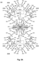
- an LSTM system configured to image two sides of a slab simultaneously has four illumination arms 303A, 303B, 303C, 303D.
- a single illumination arm of the current embodiment is shown in Fig. 5B at a larger size.
- a light source 302 applies an input LASER whose diameter is expanded by a beam expander (BE) represented by the pair of lenses 304 and 306.
- An iris 307 remove the low-intensity peripheral parts of the expanded beams.
- the beam can be selectively diverted using a pair of flipping mirrors 310 and 316 or permitted to pass directly to a cylindrical lens 318.
- the beam passes through the cylindrical lens 318, it is compressed in one dimension to generate a sheet-shaped profile. Thereafter, the beam is scanned by an optical scanning device 320, for example a one or two dimensional galvo mirror scanner.
- a first dimension of the scanner may scan the emerging sheet beam in a path that is generally perpendicular to the plane of the sheet and the second dimension, if present, may provide a degree of freedom for alignment.
- the focused sheet is then imaged on the sample via a scan lens 322 (f-theta lens which converts angular motion of Galvos to lateral motion), a tube lens 324 and the illumination objective 330, the stop 326 serving the function previously described with reference to block 140 of Fig. 2 .
- the flipping mirrors which may be motorized
- the beam is reflected and routed through a U-shaped path by mirrors 308, 314 and a relay lens system 310.
- An electrically tunable lens (ETL) 312 can be controlled electrically at high speed to allow axial displacements described in Figure 1E.
- the ETL is placed in at the conjugate focal plane by using the lens relay lens system 210.
- This selectable routing may be controlled by motorized flip mirrors 310, 316.
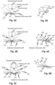
- the optical scanning device 320 allows fast lateral displacements of the final sheets as shown in Figs. 4A and 4B .
- the detection arm includes the components described above with regard to Fig. 2 , including detection objective 338, a tube lens 328 and sCMOS camera 330.
- subsystems 300A and 300B may image the same layer simultaneously, permitting the captured image data to be combined to increase resolution. Variations may also be provided such as illumination arm or arms on one side and detection arm on the opposite side of the sample. Also, the block 140 may be eliminated and also made movable so that it can be adjusted from a range of 0% blockage to a major fraction of the aperture of the illumination objective. Any of the claimed embodiments may be modified to provide additional embodiments with zero or adjustable blockage.
- any of the mirror or other deflectors such as optical scanning device 320 may be substituted by equivalent light redirectors. Such may include refracting as well as reflecting components or other types of light manipulation devices. Lenses may be of any suitable type. Wave-guide-based devices including fiber optics may also be substituted for beam reflectors. Devices other than ETLs may be employed to manipulate the axial position of the front focal plane of the illumination arm, including but not limited to, mounting of illumination objective on fast piezo motors for axial motion profile.
- the camera 330 may also be replaced, for example by a scannable line sensor. Instead of a sheet beam, a scanned pencil beam may be projected over a target illuminated linear volume 219 although such alternatives may have characteristics that are adverse to the functions of speed provided by the illustrated and described embodiments.
- a sample 336 may be mounted for translation and rotation movement, for example, mounted on an XYZ-theta motorized stage. This may permit the sample 336 to be scanned over multiple tiles.
- the illumination arm of Fig. 5B is replicated four times as shown in Fig. 5A . This allows multiple modes of illumination and image detection.
- Fig. 5A shows an LSTM system 300 with two identical LSTM subsystems 300A and 300B. Each LSTM subsystem has a respective detection arm 301A and 301B, one directed for detection at each face of the sample 336.
- Each detection arm 301A, 301B has a pair of illumination arms, detection arm 301A having illumination arms 303A and 303B and detection arm 301B having illumination arms 303C and 303D.
- the sample 336 may be surrounded by immersion liquid according to any relevant techniques.
- the four LSTM subsystems may scan at each of multiple discrete tile-specific positions of the translation system. Each scan images a layer, indicated at 332.
- the layer for each tile may be composited by stitching to form a full layer of the sample.
- the acquisition of multiple layers may be done for each tile, each layer being composited by stitching, to form a full layer. That is each tile-specific position of the translation system may acquire multiple layers.
- Figs. 5C and 5D show other variations of illumination arms that may be substituted for the illumination arms of Fig. 5A .
- Fig. 5C shows the illumination arm of Fig. 5B without the U-shaped diverted path, flipping mirrors and relay lens components. This provides the scanning functionality described relative to Fig. 5A but without the flexibility of switching the ETL in and out of the illumination arm.
- Fig. 5D shows an illumination arm suitable for the scanning mode depicted in Fig. 4A without the axial displacement of the light sheet front focal plane 241. The illumination arm of Fig. 5D has not ETL in the light path.
- a de-synchronized line- by-line detection mode for simultaneously capturing of the emitted signals is shown.
- This operating mode can be performed with the LSTM system 300 of Fig. 5A , for example.
- Illumination sheet beams 353 and 354 are directed toward a first surface of a sample and illumination sheet beams 366 and 362 are directed toward an opposite surface of the sample.
- the two pairs of illumination beams in concert with the detection arms (not shown explicitly) including camera image detectors that discriminate respective pixel columns 350 and 360 capture illuminated linear volumes 219A and 219B at laterally different positions. This arrangement minimizes light interference between the two offset targets.
- two sides of a sample can be scanned simultaneously with minimal mutual interference.
- the LSTM system may have a controller to perform a function that automatically performs a calibration by sparsely automatically sampling of the imaging planes at multiple positions in the sample.
- the LSTM system may be controlled to perform a sparse traversal of a large sample in order to extract parameters that affect the positions of the illuminated linear volumes 219 such as surface variations and variations in index of refraction.
- a sparse matrix of samples can be captured and analyzed for these variations and stored in order to create a fine traversal itinerary. This ultimately may speed and improve the imaging quality of the acquisition of optical data in a large sample.
- the traversal itinerary may employ adaptive correction of the detected parameters and interpolation of the parameters from the sparse intervals.
- the adaptive optics may correct, for example, light sheet displacement relative to the detection focal plane.
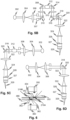
- Figs. 7A through 7E illustrate stages of a scan of a single "tile" of a larger slab which scan is performed optically for one of a matrix of positions of an X-Y-Z-theta stage that positions the slab, according to embodiments of the disclosed subject matter.
- Fig. 8 illustrates a controller connected to actuators of the various embodiments to permit automated operation of the LSTM system, according to embodiments of the disclosed subject matter.
- Fig. 7A shows illumination sheet beams 353 illuminating illuminated linear volume 219 in an initial position to the right of a tile 370 to be imaged at a fixed position of a slab 372.
- the slab may be moved by a traversing system 406 (See Fig.
- the stage may remain in a fixed position after which it's z position may be changed in steps until an entire volume is scanned and then the stage moved to a different coordinate (See Fig. 9 ) to sample an array of tiles of a slab.
- the data may be composited to form an image of the slab, as discussed.
- the illumination beam is traversed by controlling the optical scanning device 320 with the controller 410.
- the controller may position the motorized flip mirrors 310, 316 to pass illumination light through the electrically tunable lens (ETL) 312.
- ETL electrically tunable lens
- the sheet beams 353 will be moved progressively or in stages, a few of which are shown in Figs. 7A-7E .
- the exposed pixel line 204 is sampled thereby selecting a then-current line image of the illuminated linear volume 219.
- the selection of image data of the camera, storage, and sampling as well as compositing may be performed automatically by the controller 410 connected to the camera 330.
- Figs. 20A through 20D further illustrate what is happening during a scan.
- 20A and 20B show the projection of the illuminated line on the camera sensor at one end of the cross-axis scan and at an arbitrary intermediate point along the scan to an opposite end for a microscope that does not flip the position of the image across the optical axis.
- Figs. 20A and 20B show the projection of the illuminated line on the camera sensor at one end of the cross-axis scan and at an arbitrary intermediate point along the scan to an opposite end for a microscope that does flip the position of the image across the optical axis.
- Fig. 9 shows the compositing of the images of multiple tiles to create a 3D image of slab, according to embodiments of the disclosed subject matter.
- Each tile may be formed by the sequence illustrated in Figs. 7A-7E and for each, z-axis slices may be acquired.
- An array of tiles - multiple ones for each level of depth acquired - may be obtained to image a slab volume.
- the speed may be doubled by acquiring samples at two depths simultaneously using a system such as described with regard to Fig. 5A .
- Fig. 10 depicts another embodiment for implementing LSTM.
- Each of the illumination arms 500 in this embodiment includes a LASER source 502, collimators 504 (e.g., using ⁇ 10 mm output beam diameter), ETL 508, cylindrical lens 512, galvo scanner 514, scan lens 516, tube lens 520 and illumination objective 530 (e.g., a Olympus Macro 4x/0.28 NA).
- a first iris 506 is incorporated after the collimator 504 to remove the peripheral spread of Gaussian beams; a one dimensional slit 510 is incorporated before the cylindrical lens 512, to control the effective numerical aperture of illumination; and a second iris 518 is incorporated at the conjugate plane, between scan lens 516 and the tube lens 520, to control the light sheet height for minimizing unwanted illumination.
- a stop (not shown, but similar to the stop 326 in the Fig. 5A embodiment) may be provided just before the illumination objective 530.
- the illumination arms 500 are mounted at an approximately 60° angle relative to the detection arm 550 fixed on an optic table. In alternative embodiments, this angle may vary within the parameters discussed in connection with Fig. 15B .
- all the three optical arms 500, 550 may be mounted on two manual translation stages.
- an open top sample chamber filled with an immersion oil e.g., with a Refractive Index of 1.454
- samples may be mounted in a quartz cuvette attached to the base of the sample chamber.
- two thin light sheets are generated by using two illumination optical arms 500.
- the illumination objectives are air objectives
- a 3D printed cap with a coverslip e.g., a 1 inch diameter quartz coverslip
- a coverslip e.g., a 1 inch diameter quartz coverslip
- the detection arm 500 in this embodiment includes a detection objective 552 (e.g., Olympus 10x/0.6NA/8mmWD or 25x/1.0NA/8mmWD), a tube lens 556, and an sCMOS camera 558 (e.g., a Hamamatsu Orca Flash 4.0 V3).
- a detection objective 552 e.g., Olympus 10x/0.6NA/8mmWD or 25x/1.0NA/8mmWD
- sCMOS camera 558 e.g., a Hamamatsu Orca Flash 4.0 V3
- an emission filter (not shown) is disposed between the detection objective 552 and the tube lens 556.
- Table 1 A list of suitable parts and their sources that may be used in this embodiment is provided in Table 1.
- Table 1 Source Cat. Number Qty Description Detection unit Thorlabs CXY2 1 60 mm Cage System Translating Lens Mount for ⁇ 2" Optics Thorlabs LCP90F 1 60 mm Removable Cage Plate Thorlabs SM2A20 1 SM2 - M38 ADAPTER FOR NIKON TUBE LENS Thorlabs SM2L30-SM2 2 SM2 Lens Tube, 3" Thread Depth, One Retaining Ring Included Thorlabs LCP09 2 60 mm Cage Plate with ⁇ 2.2" Double Bore for SM2 Lens Tube Mounting Thorlabs ER10 4 Cage Assembly Rod, 10" Long, ⁇ 6 mm Thorlabs SM1A1 1 Adapter with External SM05 Threads and Internal SM1 Threads Thorlabs SM2A31 1 Adapter with External C-Mount Threads and Internal SM2 Threads Hamamatsu C13440
- LSTM involves scanning of a line illumination-detection profile generated by the intersection of the light sheet and the detection plane
- some preferred embodiments use static sheets (generated by the use of a cylindrical lens and associated optics), instead of a dynamic sheet (generated by rapid scanning of a pencil beam) to maximize imaging speeds.
- some alternative embodiments can use dynamic sheets.
- a galvo scanner 514 is used to achieve rapid translation of light sheets perpendicular to their propagation direction.
- rapid translation of the thinnest part of the sheet along the propagation direction is required. This may be accomplished using a variety of approaches including but not limited to using fast piezo motors to translate the illumination objectives, using holographic spatial light modulators or an electrically tunable lens (ETL) 508 to induce divergence and convergence of a collimated beam.
- ETLs electrically tunable lens
- the use of piezo motors for rapid scanning of objective often results in vibrations and require additional settling time, and the spatial light modulators are limited in modulation speed because of slower refresh rates.
- ETLs can achieve high frequency modulation of focal plane position without the need for moving optics of significant mass. Accordingly, some preferred embodiments use ETLs 508. In practice, an ETL based approach has proven to be highly effective for achieving uniform simultaneous 2-axes scanning.
- One way to optically align the LSTM assembly is to place a prism mirror (e.g., with fine scratches in the center) in the focal plane of detection optics, to visualize the location and cross- section of the light sheet relative to the detection focal plane.
- the light sheet positioning parameters can then optimized such that the thinnest part was in alignment with the center of the field-of-view of the detection plane.
- the mirror can be replaced with a high concentration (>2%) agarose gel containing fluorescent beads (Note.
- the high concentration of agarose may be used to ensure that only the surface plane of the agarose gel is visible during the alignment optimization.).
- Fig. 15A and 15B A series of calculations was used to assess and compare various properties of the Fig. 10 embodiment. The results of these calculations are summarized in Fig. 15A and 15B .
- the main physical parameters used in the calculations are the working distances and the diameters of both the illumination objectives 530 and detection objectives 552.
- the range of physically-allowable, relative angular arrangements that enable light sheets to intersect the detection focal plane at their thinnest parts were calculated.
- W1 and W2 are the working distances of the detection and illumination objectives respectively
- D1 and D2 are the diameters of the detection and illumination objectives respectively
- ⁇ i and ⁇ f are the boundary angular positions.
- Snell's law may be used to calculate the approximate effective working distance (e.g., in a refractive index liquid of 1.454, as shown in Fig. 15A ), resulting in ⁇ 44 mm, and the objective diameter (lowest part of the tapered ending) was measured to be ⁇ 28 mm.
- Fig. 15A shows approximate calculations of the effective working distance (EWD) for an Olympus Macro 4x/0.28NA/29.5WD air illumination objective when used in an immersion liquid with refractive index 1.454.
- Original working distance (OWD) is the working distance in air according to the objective specifications.
- a thin quartz coverslip and a 3D printed cap were used to seal the illumination objectives.
- EWD was estimated to be 43.84mm.
- FIG. 12 depicts the influence of angular separation of the illumination arms 500 and the detection arms 550 in the Fig. 10 embodiment on the resulting image volumes and a comparison of the illumination path length of LSTM vs. LSM.
- LSM the illumination light sheet needs to penetrate the entire width (w) of the sample ( Fig. 12B )
- LSTM the effective illumination path length depends on the angular arrangement and tissue thickness(t): t/cos( ⁇ ) where t is the sample thickness to be imaged and ⁇ is the angle between the illumination propagation direction and the detection axis ( Fig. 12A ).
- the graph in Fig. 12C plots the dependence of illumination depth of LSTM on ⁇ . Each curve represents a different tissue thickness(t), as marked by the arrow in the direction of increase in thickness.
- ⁇ tissue thickness
- b/sin( ⁇ ) which determines the axial resolution
- the graph in Fig. 12D compares the illumination depth required to image a sample of given width and thickness.
- the ratio of the LSTM and LSM illumination path was converted into a binary representation by thresholding at 1, and plotting the results as a heat map to summarize the parameters ranges where LSTM (the region on the right) and LSM (the region on the left) need smaller illumination depth, and hence which approach will provide better image quality.
- LSTM The imaging performances of LSTM and LSM was compared using a thick ( ⁇ 5mm deep and ⁇ 2 centimeters wide) cleared rat brain section stained for vasculature, with a highly transparent sample with bright uniformly distributed signal.
- LSTM enabled imaging of the entire sample with uniform high-resolution, whereas the lack of penetration of the illumination light sheets in LSM resulted in progressively poorer image quality towards the center of the tissue.
- LSTM provided rapid high-resolution quantitative imaging of these large samples without any reduction in the image quality across the sample dimensions.
- LSTM allows high-resolution quantitative imaging of large intact biological systems with no limitations on the lateral dimensions. Sample thickness that can be imaged remains limited by the working distance of the detection objective and also by level of tissue transparency and penetration of labelling reagents.
- the effective light sheet thickness can be approximated as the projection of the original thickness on to the detection direction, resulting in b /sin( ⁇ ), where b is the original light sheet thickness at the most focused position, and ⁇ is the angle of incidence relative the detection axis.
- Figs. 13A-B depict this relationship, and shows that effective planar illumination thickness can be approximated as b/sin( ⁇ ). More specifically, Fig. 13A shows the geometry and Fig. 13B plots the effective light sheet thickness as a function of ⁇ for different values of b (the arrow points in the direction of increasing b value).
- Fig. 14 depicts a comparison of energy load on the sample in LSTM and LSM.
- the two rows compare the time-accumulated energy load in LSTM and LSM for imaging a single plane ( Figs. 14A and 14C , respectively) and a single image stack tile ( Figs. 14B and 14D , respectively).
- the energy load in LSTM is dependent on the sample thickness, and in LSM on the sample width. For larger samples LSTM energy load is similar to LSM.
- Fig. 16 compares the normalized mean intensity for LSTM and LSM imaging of a ⁇ 2 cm wide and ⁇ 5 mm thick rat brain slice, stained for vasculature.
- the images used for the Fig. 16 comparison were maximum intensity z-proj ections, and were acquired using 10x/0.6NA objective.
- Fig. 16 profiles the mean (in the vertical direction) intensity across the region of interest (ROI). Due to the scattering of the illumination light sheet, the image signal in LSM is degraded towards the interior of the sample, whereas LSTM allows uniform quality imaging across the entire sample.
- ROI region of interest
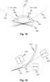
- Fig. 18 shows the relative angles formed by illumination optical axes 650 (one for each of two illumination objectives or one alone for a single illumination objective), major plane or axis 652 and 654 of the illumination beams such as when emitted from the perimeter of the objective so as to be at a shallower angle than the illumination objective optical axis 650.
- the angle 658 between the illumination objective axes 658 is smaller than the angle 656 between the major plan or axes 652 and 654.
- the drawing shows a range of angles for each that is constrained to avoid interference between a detection objective (optical axis indicated at 651) and the illumination objectives.
- Motion stage-driven microtome may also be combined with the disclosed LSTM microscope embodiments.
- the microtome may be controlled automatically, in synchrony with a tile-wise scan of a sample, to remove a layer of the sample after an outer layer has been scanned into memory. Once a layer is removed, the traversing system can move the excitation and detection arms to scan the exposed deeper layer automatically.
- a microtome may be provided for opposite surfaces of a sample, for example, separate microtomes may be provided for the opposing sample faces of the embodiment of Fig. 5A .
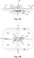
- Fig. 17A illustrates figuratively illustrates the embodiment of Fig. 5A with microtomes 610 positioned with respect to opposing faces of a sample 602 to shave, in steps, outer surfaces of the sample 602.
- a traversing attachment including a movable stage may provide X-Y, and or Z positioning of a knife 611 relative to the sample 602.
- the detection and excitation optics are indicated as outlines at 618 and 616 respectively.
- a main support is indicated at 606.
- the automatic sequential positioning of the knife may be accomplished using a very short traverse to remove a tile-sized layer at a time, or regions the size of multiple tiles may be removed at a time. At least part of the traversal of the knife may be accomplished using the traversing system used for relative positioning of the optics and 616, 618 and sample 602 during scanning.
- further processing such as compression, may be performed on acquired data in parallel with scanning.
- the data from a previous tile may be further processed to reduce the data volume, for example, by algorithms such as JPEG2000 2D or JPEG2000 3D.
- the further processing may also include other image processing tasks such as image segmentation, feature recognition or other data reduction procedures.
- a single camera can receive light, with a suitable optical arrangement, from both sides of a slab to be imaged.
- any other suitable mechanism configured to move the sheet beam waist along an axis of the illumination objective may instead, or additionally - as feasible may be employed.
- suitable mechanisms include, but are not limited to, alone or in combination, acousto-optics tunable lenses, spatial light modulators, digital micromirror devices or mounting of illumination objective on a piezo motor, gradient-index (GRIN) lenses, micro electromechanical machines (MEMS) carrying fibers, beam redirectors, for example a GRIN lens at the end of a fiber driven by a MEMS motor.
- GRIN gradient-index
- MEMS micro electromechanical machines
- Fig. 19 illustrates a fiber 670 carrying a GRIN focusing element 672 that forms a light sheet 674.
- a motor such as a piezo motor, MEMS motor, servo, stepping or any other type of motor and drive 678 may drive the GRIN lens as illustrated.
- a light source is not shown but is understood to be provided.
- a similar type of motor and drive 678 and 680 may be used to move the GRIN lens as illustrated in concert to move a line of maximum intensity light of a resulting sheet beam along a path normal to a detection objective optical axis or a single motor and drive 676 may be used to scan across the same path.
- the dashed coupling line between the motor and GRIN lens indicate mechanical coupling.
- Suitable mechanisms such as stage on tracks, linkages, or flexible composite structures can be used to maintain the orientation of the GRIN lens throughout the sweep of the scan. Note that other sweep paths may be implemented other than those shown in Figs. 4A and 4B as well as Fig. 19 such as an arc sweep or combinations of the illustrative modes.
- sCMOS camera In any embodiment described as including an sCMOS camera, other suitable imaging devices may be substituted, including, but not limited to CCD or line detectors.
- the term "objective" may refer to any lens or set of lens capable of being used as an objective or a part thereof. So, for example, the excitation arm is described, in embodiments, as using an objective to form a sheet beam. In this role it is not used for forming an image but the optical element itself may have features of an objective including characterizing features such as a numerical aperture.
- provisions may be made to alter the depth of field of the microscope and to select a number of depths to scan for a given tile in order to increase the speed of throughput for live imaging of tissue samples, for example.
- the depth of field may be selected by any suitable mechanism such as an objective turret selector or replaceable objectives.
- an optical imaging apparatus includes a first illumination arm having optical components arranged for forming a first sheet beam.
- a first detection arm has a front focal plane and having optical components for imaging a linear volume where the sheet beam intersects the front focal plane.
- the first illumination arm and first detection arm optical components each include a respective illumination objective and detection objective, the angle of the first sheet beam is oblique to the optical axis of the illumination objective, and the first detection arm front focal plane is perpendicular to the detection objective.
- the first embodiments include variants in which the first illumination arm optical components include scanning components that cause a beam waist of the sheet beam to traverse the first detection arm front focal plane.
- the first embodiments include variants that include a controller connected to a first camera to read image data therefrom, wherein the first detection arm includes a two-dimensional image detector of the camera, the controller reading and storing selected pixels of the image detector responsively to positions of the sheet beam waist, thereby causing the selected pixels to follow the traversal of the beam waist.
- the first embodiments include variants in which the controller controls the scanning components.
- the scanning components include an electrically tunable lens configured to move the sheet beam waist along an axis of the illumination objective.
- the first embodiments include variants that include a traversing system, the controller configured to control the scanning components and to form an image slice from successive samples of the linear volume.
- the first embodiments include variants that include a second illumination arm identical to the first and configured to form a second sheet beam that intersects the first sheet beam.
- the first embodiments include variants in which the first and second illumination arm illumination objective optical axes each forms an angle to the surface of the first detection arm front focal plane.
- each of the illumination arms includes a partial beam block which causes the sheet beam to be formed using a side portion of the illumination objective.
- the first embodiments include variants in which the angles of the sheet beams are responsive to the position of the beam block.
- the first embodiments include variants that include a controller connected to a traversal system, the controller is programmed to optically scan portions of a degree of freedom of the traversing system such that the traversing system can move in steps along an axis corresponding to the degree of freedom whose size is responsive to a dimension of the optical scan, to permit the capture of a sample larger than the dimension of the optical scan.
- the first embodiments include variants that include a second illumination arm and a second detection arm, both identical, respectively, to the first illumination and detection arms, the second illumination and detection arms is positioned on opposite sides of a movable stage.
- the first embodiments include variants that include cameras on each of the first and second illumination arms, a controller connected to first and second image detectors to read image data therefrom, wherein the first detection arms each includes a two-dimensional image detector of the camera, the controller reading and storing selected pixels of the image detector responsively to positions of the sheet beam waist, thereby causing the selected pixels to follow the traversal of the beam waist.
- the first embodiments include variants in which the controller is configured to control the sheet beams of the first and second illumination arms to maintain a distance between the intersections of the sheet beams and the front focal planes of the detection arms.
- the first embodiments include variants in which the controller is configured to control the sheet beams of the first and second illumination arms to maintain a distance between the intersections of the sheet beams and the front focal planes of the detection arms by maintain a phase difference between the scan cycling of the two sheet beams.
- the disclosed subject matter includes a method of imaging an elongate volume within a sample.
- the method includes forming a sheet beam by passing a beam of light through a side of a first objective such that the beam is blocked from passing through a portion to a side of an optical axis of the first objective.
- the method includes detecting light from a linear volume illuminated by the sheet where the sheet intersects the focal plane of the first objective or a second objective.
- the forming includes scanning the illumination beam such that the linear volume traverses an axis that is perpendicular to an axis of the linear volume.
- the second embodiments include variants in which the detecting includes sampling a line of pixels of a two-dimensional image plane of a camera, the line of pixels coinciding with an image of the linear volume.
- the second embodiments include variants in which the first objective or a second objective is the first objective.
- the second embodiments include variants in which the first objective or a second objective is a second objective.
- the second embodiments include variants in which the scanning includes traversing an axial position of the linear volume along an axis of the first objective.
- the second embodiments include variants in which the traversing an axial position includes actuating an electrically tunable lens.
- the second embodiments include variants that include repeating the forming and detecting on an opposite side of a single sample.
- the second embodiments include variants that include mechanically traversing a sample after each of the steps of scanning and repeating the forming and detecting at each position of the mechanically traversing and compositing the images corresponding to each scan to form a three-dimensional image of a sample.
- the disclosed subject matter includes a microscope.
- a detection objective has optical axis is at a normal to a predefined plane defined by two axes of a traversing system.
- One or more illumination objectives are positioned and oriented to generate one or more light sheets at an angle oblique to the normal such that the light sheets enter the sample from the same side of the predefined plane as the detection objective.
- the third embodiments include variants that include a detection arm that conveys light from the detection objective to a two-dimensional image sensor.
- the third embodiments include variants in which the image sensor is a sCMOS type sensor.
- the third embodiments include variants that include illumination arms that form beams that pass through the illumination objectives.
- the third embodiments include variants in which the illumination arms are configured to pass light asymmetrically through the illumination objectives such that the light sheets form an angle relative to the illumination objective optical axes.
- the third embodiments include variants in which the illumination arms each block a beam applied to a respective one of the illumination objectives.
- the third embodiments include variants that include a controller and scanning optics controlled by the controller in the illumination arms to cause an intersection between the light sheets and a front focal plane of the detection objective to traverse the front focal plane.
- the third embodiments include variants that include the controller captures a line of pixels of an imaging device corresponding to an image of an illuminated region located at the intersection.
- the disclosed subject matter includes a microscope.
- An imaging component has an imaging objective.
- a first light sheet projector is located on a same side of a sample region as the imaging component.
- the imaging component itself can include all the part of a conventional microscope, for example.
- the imaging objective and first light sheet projector have respective optical axes that intersect in the sample region. This occurs because of the way they are positioned and oriented in a common mounting with the microscope.
- a sample support is positioned and oriented with respect to the imaging objective such that, when a sample is placed on the sample support, the imaging objective optical axis is perpendicular to a surface of the sample.
- the sample support is a generally flat element has a major plane and shaped to hold a slab-shaped sample, the imaging objective optical axis is perpendicular to the major plane.
- a second light sheet projector is also provided.
- the second light sheet projector has an optical axis forming an angle with the imaging objective optical axis equal to an angle formed by the first sheet projector optical axis with the imaging objective optical axis.
- the disclosed subject matter includes a microscope with an imaging component, has an imaging objective, and a first light sheet projector located on a same side of a sample region.
- the imaging objective and first light sheet projector have respective axes that intersect in the sample region.
- a sample support is positioned to hold a sample in the sample region.
- the light sheet projector has light scanning and focusing optics to permit the selection of an axial position of a light sheet beam waist and the selection of a position of the light sheet along an axis perpendicular to the light sheet propagation direction.
- a controller is connected to control the light scanning and focusing optics to translate the beam waste along a linear path.
- the imaging objective optical axis are perpendicular to the linear path.
- the focusing optics include an electrically tunable lens (ETL).
- the sample support is a generally flat element shaped to hold a slab-shaped sample.
- a second light sheet projector has an optical axis forming an angle with the imaging objective optical axis equal to an angle formed by the first sheet projector optical axis with the imaging objective optical axis.
- one or more further light sheet projectors and an imaging component are arranged on an opposite side of the sample region such that two opposite faces of a sample can be scanned.
- a translating stage is connected to move the sample support to permit the sequential scanning of portions of a sample.
- the disclosed subject matter includes a microscope with an imaging objective and a first light sheet projector located on a same side of a sample region.
- the imaging objective and first light sheet projector have respective optical axes that intersect in the sample region.
- a sample support is provided on a translating stage that translates the sample support along at least one linear axis.
- the translating stage is positioned and oriented with respect to the imaging objective such that the imaging objective optical axis is perpendicular to the at least one linear axis.
- the sample support may be a generally flat element has a major plane and shaped to hold a slab-shaped sample, the imaging objective optical axis is perpendicular to the major plane.
- a second light sheet projector may be provided having an optical axis forming an angle with the imaging objective optical axis equal to an angle formed by the first sheet projector optical axis with the imaging objective optical axis.
- any of the microscope embodiments may include one or more further light sheet projectors and an imaging component arranged on an opposite side of the sample region such that two opposite faces of a sample can be scanned and/or a translating stage connected to move the sample support to permit the sequential scanning of portions of a sample.
- the disclosed subject matter includes an imaging instrument including a microscope with an objective has an optical axis.
- a first light beam projector has imaging optics separate from the microscope positioned to direct a beam of light that crosses the optical axis.
- the first light beam projector forms a sheet has a beam waist in the form of a line of maximum intensity.
- the first light beam projector has a scanning mechanism that scans the line of maximum intensity through a range of positions along a scan direction perpendicular to the line of maximum intensity.
- the microscope objective optical axis is perpendicular to the scan direction.
- the objective and the light beam projector are located on a same side of a sample volume such that an extended slab-shaped sample can be scanned by moving the sample relative to the objective and the light beam projector.
- a traversing system may be connected to one or both of the microscope and a sample support to move them such that a slab-shaped sample can be scanned.
- the traversing system is an X-Y traversing system.
- the traversing system is an X-Y traversing system, where X and Y axes are perpendicular to the optical axis.
- a controller may be connected to the traversing system and scanning mechanism to scan each of multiple tile segments of a sample using the scanning mechanism and to shift the sample support relative to the microscope to scan additional tile segment.
- the scanning mechanism includes electrically tunable lens (ETL).
- ETL electrically tunable lens
- the ETL may change a position of the line of maximum intensity along a length of the sheet in the direction of propagation of the sheet.
- the scanning mechanism includes a light redirector that scans the sheet such that the line of maximum intensity traverses an axis perpendicular to a direction of propagation of the sheet.
- the scanning mechanism may include a light redirector that scans the sheet such that the line of maximum intensity traverses an axis perpendicular to a direction of propagation of the sheet.
- the scanning mechanism may include a light redirector that scans the sheet such that the line of maximum intensity traverses an axis perpendicular to a direction of propagation of the sheet.
- the light redirector may include a galvo-motor.
- the light redirector may include a galvo-mirror.
- the scanning mechanism may scan in two axes, one to changes a position of the line of maximum intensity along a length of the sheet in the direction of propagation of the sheet and one to change the position of the line of maximum intensity along an axis perpendicular to the direction of propagation of the sheet.
- the scanning mechanism may scan in two axes, one to changes a position of the line of maximum intensity along a length of the sheet in the direction of propagation of the sheet and one to change the position of the line of maximum intensity along an axis perpendicular to the direction of propagation of the sheet.
- the scanning mechanism may include an electrically tunable lens (ETL) to change the position of the line of maximum intensity along a length of the sheet in the direction of propagation of the sheet.
- ETL electrically tunable lens
- the disclosed subject matter includes an imaging instrument that includes a microscope with an objective.
- a first light beam projector has imaging optics separate from the microscope positioned to direct a beam of light that crosses the optical axis.
- the first light beam projector forms a sheet that has a beam waist in the form of a line of maximum intensity.
- the first light beam projector has a scanning mechanism that scans the line of maximum intensity through a range of positions along a scan direction perpendicular to the line of maximum intensity.
- the objective and the light beam projector are located on a same side of a sample volume such that an extended slab-shaped sample can be scanned by moving the sample relative to the objective and the light beam projector.
- the disclosed subject matter includes the microscopes include a traversing system connected to one or both of the microscope and a sample support to move them such that a slab-shaped sample can be scanned.
- the traversing system is an X-Y traversing system.
- the traversing system is an X-Y-Z traversing system, where X and Y axes are parallel to a major plane of the sample volume and the Z axis is perpendicular thereto.
- a controller is connected to the traversing system and scanning mechanism to scan each of multiple tile segments of a sample using the scanning mechanism and to shift the sample support relative to the microscope to scan additional tile segment.
- the scanning mechanism includes electrically tunable lens (ETL).
- ETL changes a position of the line of maximum intensity along a length of the sheet in the direction of propagation of the sheet.
- the scanning mechanism includes a light redirector that scans the sheet such that the line of maximum intensity traverses an axis perpendicular to a direction of propagation of the sheet.
- the scanning mechanism includes a light redirector that scans the sheet such that the line of maximum intensity traverses an axis perpendicular to a direction of propagation of the sheet.
- the scanning mechanism includes a light redirector that scans the sheet such that the line of maximum intensity traverses an axis perpendicular to a direction of propagation of the sheet.
- the light redirector includes a galvo-motor.
- the light redirector includes a galvo-mirror.
- the scanning mechanism scans in two axes, one to changes a position of the line of maximum intensity along a length of the sheet in the direction of propagation of the sheet and one to change the position of the line of maximum intensity along an axis perpendicular to the direction of propagation of the sheet.
- the scanning mechanism scans in two axes, one to changes a position of the line of maximum intensity along a length of the sheet in the direction of propagation of the sheet and one to change the position of the line of maximum intensity along an axis perpendicular to the direction of propagation of the sheet.
- the scanning mechanism includes electrically tunable lens (ETL) to change the position of the line of maximum intensity along a length of the sheet in the direction of propagation of the sheet.
- ETL electrically tunable lens
- the disclosed subject matter includes a method of acquiring a three-dimensional image of a sample.
- the method includes projecting a beam of light into a sample, the beam has a line of maximum intensity perpendicular to a direction of propagation of the beam and scanning the beam to scan the line of maximum intensity along a path oblique to both the direction of propagation and perpendicular to it.
- the method may include capturing images of the line on respective portions of an imaging transducer.
- the method may be such that, additionally or alternatively, such that the imaging transducer includes a camera sensor.
- the method may be such that, additionally or alternatively, such that the capturing includes imaging light from the line using a microscope.
- the method may be such that, additionally or alternatively, such that the capturing includes receiving and imaging secondary light induced by the line of maximum intensity.
- the method may be such that, additionally or alternatively, such that the capturing includes receiving and imaging a region of fluorescence induced by the line of maximum intensity.
- the method may be such that, additionally or alternatively, such that the scanning includes mechanically moving the end of a wave guide.
- the method may include, additionally or alternatively, moving the sample relative to the microscope and the beam of light and repeating the scanning and capturing for a different region of the sample.
- the method may include, additionally or alternatively, creating two-dimensional images from the capturing and stitching them together to form larger composite images by matching features of the edges of the images.
- the method may be such that, additionally or alternatively, such that the moving includes moving in one or all of three orthogonal directions.
- the method may be such that, additionally or alternatively, such that the moving includes moving in all of three orthogonal directions to traverse a three-dimensional volume of positions.
- the method may include, additionally or alternatively, changing the focus of an imaging device to optically discriminate multiple depths of the sample after each scan of the scanning.
- the method may be such that, additionally or alternatively, such that the light sheet projector includes a GRIN lens as an objective.
- the disclosed subject matter includes a microscopy method that includes positioning a detection objective oriented with its optical axis perpendicular to a facing surface of a sample slab.
- the method further includes positioning an excitation objective oriented to form an acute angle with the detection objective optical axis.
- the positioning a detection objective and the positioning an excitation objective is such that the detection and excitation objectives is on a same side of the sample slab.
- the method further includes applying light off-center to the back aperture of the excitation objective such that a beam emerges at an angle with respect to an optical axis of the excitation objective and with a major axis parallel to its direction of propagation that forms a larger angle than the acute angle.
- the method may be such that, additionally or alternatively, such that the applying includes partially optically blocking the back aperture.
- the method may be such that, additionally or alternatively, such that the major axis forms a more acute angle with the facing surface than the detection objective optical axis.
- the disclosed subject matter includes a microscopy method that includes arranging a detection objective of a microscope with its optical axis normal to a surface of a sample slab and injecting light along directions forming equal and opposite angles with the detection objective optical axis.
- the method includes imaging light resulting from the injecting using the microscope.
- the method may be such that, additionally or alternatively, such that the light resulting from the injecting includes fluorescence.
- the method may be such that, additionally or alternatively, such that the injecting results in a single line-shaped region of maximum light intensity in the sample.
- the method may include, additionally or alternatively, scanning the region perpendicular to a major axis thereof to trace out a planar segment of the sample while sampling the light resulting from the injecting using a light sensor.
- the method may be such that, additionally or alternatively, such that the sensor includes a camera.
- the method may be such that, additionally or alternatively, such that the imaging includes receiving the resulting slight through a microscope.
- the method may be such that, additionally or alternatively, such that the detection objective is an objective of a microscope.
- the method may, additionally or alternatively, include scanning the region perpendicular to a major axis thereof to trace out a planar segment of the sample that is parallel to the sample surface while sampling the light resulting from the injecting using a light sensor.
- the disclosed subject matter includes a microscope with at least two excitation optical elements arranged to form and direct respective sheets of light such that they intersect to form an illuminated line of intersection in a sample region, the sheets has major planes that form angles of at least 75 degrees.
- a detection optical element is arranged with respect to the excitation optical elements with an optical axis forming equal angles with the major planes of the sheets.
- At least two excitation optical elements include objective lenses.
- at least two excitation optical elements include objective lenses each has an adjustable partial beam block to cause the sheet beam to be emerge from a side portion of the objective.
- at least two excitation optical elements include GRIN lenses.
- the two excitation optical elements include scanning optical elements arranged to cause the illuminated line to traverse the sample region.
- the two excitation optical elements include scanning optical elements arranged to cause the illuminated line to traverse the sample region along a focal plane of the detection optical element.
- a traversing system is provided and the controller is configured to control scanning components and to form an image slice from successive detections of the sample region.
- the disclosed subject matter includes a microscope.
- First and second imaging components each have an imaging objective, and first and second light sheet projectors each located on a same side of a sample region as a respective on of the first and second imaging components.
- Each imaging objective and each light sheet projector has respective axes that intersect in the sample region.
- a sample support is positioned to hold a sample in the sample region.
- Each light sheet projector has light scanning and focusing optics to permit the selection of an axial position of a light sheet beam waist and the selection of a position of the light sheet along an axis perpendicular to the light sheet propagation direction.
- a controller is connected to control the light scanning and focusing optics to translate the beam waste of each light sheet projector independently along a respective linear path.
- the imaging objective optical axes are perpendicular to a respective one of the linear paths. In variations, the imaging objective optical axes are perpendicular to a both of the linear paths.
- the focusing optics include an electrically tunable lens (ETL).
- the sample support is a generally flat element shaped to hold a slab-shaped sample.
- the processor can include, but not be limited to, a personal computer or workstation or other such computing system that includes a processor, microprocessor, microcontroller device, or is comprised of control logic including integrated circuits such as, for example, an Application Specific Integrated Circuit (ASIC).
- ASIC Application Specific Integrated Circuit
- the instructions can be compiled from source code instructions provided in accordance with a programming language such as Java, C++, C#.net or the like.
- the instructions can also comprise code and data objects provided in accordance with, for example, the Visual Basic TM language, LabVIEW, or another structured or object-oriented programming language.
- a non-transitory computer-readable medium such as a computer memory or storage device which may be any suitable memory apparatus, such as, but not limited to read-only memory (ROM), programmable read-only memory (PROM), electrically erasable programmable read-only memory (EEPROM), random-access memory (RAM), flash memory, disk drive and the like.
- ROM read-only memory
- PROM programmable read-only memory
- EEPROM electrically erasable programmable read-only memory
- RAM random-access memory
- flash memory disk drive and the like.
- modules, processes, systems, and sections can be implemented as a single processor or as a distributed processor. Further, it should be appreciated that the steps mentioned above may be performed on a single or distributed processor (single and/or multi-core). Also, the processes, modules, and sub-modules described in the various figures of and for embodiments above may be distributed across multiple computers or systems or may be co-located in a single processor or system. Exemplary structural embodiment alternatives suitable for implementing the modules, sections, systems, means, or processes described herein are provided below.
- the modules, processors or systems described above can be implemented as a programmed general purpose computer, an electronic device programmed with microcode, a hard-wired analog logic circuit, software stored on a computer-readable medium or signal, an optical computing device, a networked system of electronic and/or optical devices, a special purpose computing device, an integrated circuit device, a semiconductor chip, and a software module or object stored on a computer-readable medium or signal, for example.
- Embodiments of the method and system may be implemented on a general-purpose computer, a special-purpose computer, a programmed microprocessor or microcontroller and peripheral integrated circuit element, an ASIC or other integrated circuit, a digital signal processor, a hardwired electronic or logic circuit such as a discrete element circuit, a programmed logic circuit such as a programmable logic device (PLD), programmable logic array (PLA), field-programmable gate array (FPGA), programmable array logic (PAL) device, or the like.
- PLD programmable logic device
- PLA programmable logic array
- FPGA field-programmable gate array
- PAL programmable array logic
- any process capable of implementing the functions or steps described herein can be used to implement embodiments of the method, system, or a computer program product (software program stored on a non-transitory computer readable medium).
- embodiments of the disclosed method, system, and computer program product may be readily implemented, fully or partially, in software using, for example, object or object-oriented software development environments that provide portable source code that can be used on a variety of computer platforms.
- embodiments of the disclosed method, system, and computer program product can be implemented partially or fully in hardware using, for example, standard logic circuits or a very-large-scale integration (VLSI) design.
- VLSI very-large-scale integration
- Other hardware or software can be used to implement embodiments depending on the speed and/or efficiency requirements of the systems, the particular function, and/or particular software or hardware system, microprocessor, or microcomputer being utilized.
- Embodiments of the method, system, and computer program product can be implemented in hardware and/or software using any known or later developed systems or structures, devices and/or software by those of ordinary skill in the applicable art from the function description provided herein and with a general basic knowledge of control systems, kinematic design, optics, microscopy and/or computer programming arts.
- embodiments of the disclosed method, system, and computer program product can be implemented in software executed on a programmed general purpose computer, a special purpose computer, a microprocessor, or the like.
Landscapes
- Physics & Mathematics (AREA)
- General Physics & Mathematics (AREA)
- Chemical & Material Sciences (AREA)
- Analytical Chemistry (AREA)
- Optics & Photonics (AREA)
- Health & Medical Sciences (AREA)
- Multimedia (AREA)
- Engineering & Computer Science (AREA)
- Nuclear Medicine, Radiotherapy & Molecular Imaging (AREA)
- Life Sciences & Earth Sciences (AREA)
- Biochemistry (AREA)
- General Health & Medical Sciences (AREA)
- Immunology (AREA)
- Pathology (AREA)
- Computer Vision & Pattern Recognition (AREA)
- Microscoopes, Condenser (AREA)
- Investigating, Analyzing Materials By Fluorescence Or Luminescence (AREA)
Claims (13)
- Ein Abbildungsinstrument, aufweisend:ein Mikroskop; undeinen ersten Lichtstrahlprojektor (142; 330; 530), wobeidas Mikroskop ein Erfassungsobjektiv (104; 338; 552) mit einer optischen Achse senkrecht zu einer vordefinierten Ebene hat, die durch zwei Achsen eines Verschiebesystems (406) definiert ist;der erste Lichtstrahlprojektor (142; 330; 530) eine von dem Mikroskop separate Abbildungsoptik hat;der erste Lichtstrahlprojektor (142; 330; 530) einen Lichtschnitt (144; 210, 212; 237, 239) mit einer Strahltaille in Form einer Linie maximaler Intensität ausbildet;der erste Lichtstrahlprojektor (142; 330; 530) positioniert ist, um den Lichtschnitt (144; 210, 212; 237, 239), der die optische Achse in einem Winkel schräg zur Normalen kreuzt, zu führen, so dass der Lichtschnitt (144; 210, 212; 237, 239) in eine Probe (336) von derselben Seite der vordefinierten Ebene eintritt, an der sich das Detektionsobjektiv (104; 338; 552) befindet; undder erste Lichtstrahlprojektor (142; 330; 530) einen Abtastmechanismus (320) hat, der die Linie maximaler Intensität durch einen Bereich von Positionen entlang einer Abtastrichtung senkrecht zur Linie maximaler Intensität abtastet.
- Das Abbildungsinstrument gemäß Anspruch 1, wobei das Erfassungsobjektiv (104; 338; 552) und der
Lichtstrahlprojektor (142; 330; 530) an derselben Seite eines Probenvolumens angeordnet sind, so dass eine sich plattenförmige erstreckende Probe (336) durch Bewegen der Probe relativ zum Erfassungsobjektiv (104; 338; 552) und zum ersten Lichtstrahlprojektor (142; 330; 530) abgetastet werden kann. - Das Abbildungsinstrument gemäß Anspruch 1, ferner das mit einem oder beiden von dem Mikroskop und einem Probenträger verbundene Verschiebesystem (406) aufweisend, um diese so zu bewegen, dass eine plattenförmige Probe (336) abgetastet werden kann.
- Das Abbildungsinstrument gemäß Anspruch 3, wobei das Verschiebesystem (406) ein X-Y-Verschiebesystem ist.
- Das Abbildungsinstrument gemäß Anspruch 3, wobei das Verschiebesystem (406) ein X-Y-Z-Verschiebesystem ist, wobei die X- und Y-Achse parallel zu einer Hauptebene des Probenvolumens sind und die Z-Achse senkrecht dazu ist.
- Das Abbildungsinstrument gemäß Anspruch 3, ferner eine Steuereinheit (410) aufweisend, die mit dem Verschiebesystem (406) und dem Abtastmechanismus (320) verbunden ist, um jedes von mehreren Kachelsegmenten der Probe (336) unter Verwendung des Abtastmechanismus (320) abzutasten und den Probenträger relativ zum Mikroskop zu verschieben, um ein zusätzliches Kachelsegment abzutasten.
- Das Abbildungsinstrument gemäß einem der Ansprüche 1 bis 6, wobei der Abtastmechanismus (320) eine elektrisch abstimmbare Linse (312; 508) aufweist.
- Das Abbildungsinstrument gemäß Anspruch 7, wobei die elektrisch abstimmbare Linse (312; 508) eine Position der Linie maximaler Intensität entlang einer Länge des Lichtschnitts (144; 210, 212; 237, 239) in Ausbreitungsrichtung des Lichtschnitts ändert.
- Das Abbildungsinstrument gemäß Anspruch 7, wobei der Abtastmechanismus (320) einen Lichtumlenker aufweist, der den Lichtschnitt (144; 210, 212; 237, 239) so abtastet, dass die Linie maximaler Intensität eine Achse senkrecht zu einer Ausbreitungsrichtung des Lichtschnitts durchläuft.
- Das Abbildungsinstrument gemäß Anspruch 9, wobei der Lichtumlenker einen Galvomotor aufweist.
- Das Abbildungsinstrument gemäß Anspruch 9, wobei der Lichtumlenker einen Galvospiegel aufweist.
- Das Abbildungsinstrument gemäß einem der Ansprüche 1 bis 6, 10 und 11, wobei der Abtastmechanismus (320) in zwei Achsen abtastet, eine, um eine Position der Linie maximaler Intensität entlang einer Länge des Lichtschnitts (144; 210, 212; 237, 239) in der Ausbreitungsrichtung des Lichtschnitts zu ändern, und eine, um die Position der Linie maximaler Intensität entlang einer Achse senkrecht zur Ausbreitungsrichtung des Lichtschnitts zu ändern.
- Das Abbildungsinstrument gemäß Anspruch 12, wobei der Abtastmechanismus (320) eine elektrisch abstimmbare Linse (312; 508) aufweist, um die Position der Linie maximaler Intensität entlang einer Länge des Lichtschnitts (144; 210, 212; 237, 239) in der Ausbreitungsrichtung des Lichtschnitts zu ändern.
Applications Claiming Priority (3)
| Application Number | Priority Date | Filing Date | Title |
|---|---|---|---|
| US201662420349P | 2016-11-10 | 2016-11-10 | |
| US201762473944P | 2017-03-20 | 2017-03-20 | |
| PCT/US2017/061165 WO2018089839A1 (en) | 2016-11-10 | 2017-11-10 | Rapid high-resolution imaging methods for large samples |
Publications (3)
| Publication Number | Publication Date |
|---|---|
| EP3538941A1 EP3538941A1 (de) | 2019-09-18 |
| EP3538941A4 EP3538941A4 (de) | 2020-06-17 |
| EP3538941B1 true EP3538941B1 (de) | 2025-04-23 |
Family
ID=62110546
Family Applications (1)
| Application Number | Title | Priority Date | Filing Date |
|---|---|---|---|
| EP17868760.4A Active EP3538941B1 (de) | 2016-11-10 | 2017-11-10 | Schnelles hochauflösendes bildgebungsverfahren für grosse proben |
Country Status (4)
| Country | Link |
|---|---|
| US (2) | US11506877B2 (de) |
| EP (1) | EP3538941B1 (de) |
| JP (1) | JP2020502558A (de) |
| WO (1) | WO2018089839A1 (de) |
Families Citing this family (23)
| Publication number | Priority date | Publication date | Assignee | Title |
|---|---|---|---|---|
| CN109425592B (zh) * | 2017-08-31 | 2021-06-01 | 清华大学 | 一种一维纳米材料的观测装置 |
| US20210239955A1 (en) * | 2018-06-08 | 2021-08-05 | The Board Of Trustees Of The Leland Stanford Junior University | Near infra-red light sheet microscopy through scattering tissues |
| JP7018006B2 (ja) * | 2018-09-27 | 2022-02-09 | 富士フイルム株式会社 | 試料撮影装置 |
| IL263106B2 (en) * | 2018-11-19 | 2023-02-01 | Nova Ltd | Integrated measurement system |
| WO2020106972A1 (en) * | 2018-11-21 | 2020-05-28 | The Board Of Trustees Of The Leland Stanford Junior University | Wide-field nanosecond imaging methods using wide-field optical modulators |
| DE102019207873B4 (de) * | 2019-05-29 | 2021-10-14 | Leica Microsystems Cms Gmbh | Optischer Aufbau für ein Mikroskop und Mikroskop |
| EP3786685A1 (de) * | 2019-09-02 | 2021-03-03 | Leica Microsystems CMS GmbH | Steuerungsvorrichtung und verfahren zur steuerung eines mikroskops, mikroskop und computerprogrammprodukt |
| DE102019214929B4 (de) * | 2019-09-27 | 2022-02-10 | Leica Microsystems Cms Gmbh | Kompaktes Lichtblattmikroskop und Verwendung eines auf endlich korrigierten Objektivs in einem Lichtblattmikroskop |
| AU2020382640A1 (en) * | 2019-11-13 | 2022-05-19 | University Of Washington | Open-top light-sheet microscopy with a non-orthogonal arrangement of illumination and collection objectives |
| WO2021159285A1 (zh) * | 2020-02-12 | 2021-08-19 | 深圳华大智造科技股份有限公司 | 光学成像系统及应用所述光学成像系统的生化物质检测系统 |
| EP4211508B1 (de) * | 2020-09-14 | 2025-11-26 | Singular Genomics Systems, Inc. | Verfahren und systeme zur mehrdimensionalen bildgebung |
| JP7767429B2 (ja) * | 2020-12-15 | 2025-11-11 | ザ・トラスティーズ・オブ・コロンビア・ユニバーシティ・イン・ザ・シティ・オブ・ニューヨーク | 生体内のボリュメトリック組織学的画像のリアルタイムでの取得のためのポイントオブケア顕微鏡 |
| CN117043655A (zh) * | 2021-01-22 | 2023-11-10 | 维微恩提斯显微镜有限责任公司 | 用于对样品进行成像的显微镜 |
| CN112785525B (zh) * | 2021-01-26 | 2022-08-16 | 桂林电子科技大学 | 基于深度学习去除刀具刃口图像中的附着物的方法和系统 |
| DE102021107821B4 (de) | 2021-03-29 | 2023-05-11 | Universität Kassel, Körperschaft des öffentlichen Rechts | Lichtblatt-fluoreszenzmikroskop und verfahren zur tomographischen darstellung |
| CN113310964B (zh) * | 2021-06-02 | 2022-04-05 | 华中科技大学 | 一种兼容微流控芯片的数字扫描光片显微成像系统 |
| US20240427129A1 (en) * | 2021-09-22 | 2024-12-26 | Howard Hughes Medical Institute | Multiscale multiview light-sheet imaging |
| US20250052986A1 (en) * | 2021-10-13 | 2025-02-13 | Fluorescence Microscopy Business Unit (FMBU) of Bruker Nano Surfaces Division | Method and apparatus for rapid depth-scanning in laser imaging |
| WO2024026145A1 (en) * | 2022-07-29 | 2024-02-01 | Advanced Optical Technologies, Inc. | Quantitative wide field polarized light microscope |
| DE102022125117A1 (de) | 2022-09-29 | 2024-04-04 | Carl Zeiss Microscopy Gmbh | Lichtblattmikroskop |
| DE102023109270B3 (de) * | 2023-04-13 | 2024-08-14 | Schölly Fiberoptic GmbH | Beleuchtungssystem, zugehörige Verwendung, Beobachtungssystem, sowie Verfahren zum Erzeugen eines Beleuchtungsfelds |
| WO2025199301A1 (en) * | 2024-03-20 | 2025-09-25 | The Trustees Of Columbia University In The City Of New York | Scalable projected light sheet microscopy for high-resolution imaging of living and cleared samples |
| WO2025196176A1 (en) | 2024-03-21 | 2025-09-25 | Miltenyi Biotec B.V. & Co. KG | Wavefront shaping for digital light sheet microscopy |
Citations (1)
| Publication number | Priority date | Publication date | Assignee | Title |
|---|---|---|---|---|
| US20150253560A1 (en) * | 2012-10-23 | 2015-09-10 | Karlsruher Institut für Technologie | Microscope with at least one illuminating beam in the form of a light sheet |
Family Cites Families (463)
| Publication number | Priority date | Publication date | Assignee | Title |
|---|---|---|---|---|
| US652581A (en) | 1900-03-01 | 1900-06-26 | Ayars Machine Co | Can topping and wiping machine. |
| DE2542355A1 (de) | 1975-09-19 | 1977-03-24 | Siemens Ag | Durchstrahlungs-raster-elektronenmikroskop mit ringscheibenfoermigem detektor |
| US4181436A (en) | 1975-09-25 | 1980-01-01 | Ernst Leitz Wetzlar Gmbh | Microscope scanning accessory for a photometer |
| JPS53135660A (en) | 1977-04-30 | 1978-11-27 | Olympus Optical Co Ltd | Fluorescent photometric microscope using laser light |
| US4218112A (en) | 1978-07-03 | 1980-08-19 | C. Reichert Optische Werke, Ag | Photometer microscope for microphotometer scanning of fine specimen structures |
| JPS56121151U (de) | 1980-02-15 | 1981-09-16 | ||
| NL8103505A (nl) | 1981-07-24 | 1983-02-16 | Philips Nv | Inrichting voor het puntsgewijs aftasten van een voorwerp. |
| GB2130433B (en) | 1982-03-05 | 1986-02-05 | Jeol Ltd | Scanning electron microscope with as optical microscope |
| GB8301096D0 (en) | 1983-01-15 | 1983-02-16 | Cambridge Instr Ltd | Electron scanning microscopes |
| SE455736B (sv) | 1984-03-15 | 1988-08-01 | Sarastro Ab | Forfaringssett och anordning for mikrofotometrering och efterfoljande bildsammanstellning |
| DE3422143A1 (de) | 1984-06-14 | 1985-12-19 | Josef Prof. Dr. Bille | Geraet zur wafer-inspektion |
| US4627730A (en) | 1984-07-06 | 1986-12-09 | The Board Of Trustees Of The Leland Stanford Junior University | Optical scanning microscope |
| NL8402340A (nl) | 1984-07-25 | 1986-02-17 | Philips Nv | Microscoop voor niet-gedifferentieerde fase-beeldvorming. |
| US4700298A (en) | 1984-09-14 | 1987-10-13 | Branko Palcic | Dynamic microscope image processing scanner |
| DE3610165A1 (de) | 1985-03-27 | 1986-10-02 | Olympus Optical Co., Ltd., Tokio/Tokyo | Optisches abtastmikroskop |
| JPH0713707B2 (ja) | 1985-04-26 | 1995-02-15 | オリンパス光学工業株式会社 | 走査型光学顕微鏡 |
| DE3531129A1 (de) | 1985-08-30 | 1987-03-12 | Siemens Ag | Verfahren und anordnung zum betrieb eines rastermikroskopes |
| JPS62138819A (ja) | 1985-12-13 | 1987-06-22 | Hitachi Ltd | 走査型レ−ザ顕微鏡 |
| EP0262222A4 (de) | 1986-04-09 | 1989-02-22 | Sapporo Breweries | Mikroskop mit automatischer abtastung. |
| JPS62255912A (ja) | 1986-04-30 | 1987-11-07 | Hitachi Ltd | 走査光子顕微鏡 |
| JPH0718975B2 (ja) | 1986-06-20 | 1995-03-06 | オリンパス光学工業株式会社 | 走査型光学顕微鏡 |
| GB8617570D0 (en) | 1986-07-18 | 1986-08-28 | See C W | Microscopes |
| US4806004A (en) | 1987-07-10 | 1989-02-21 | California Institute Of Technology | Scanning microscopy |
| NL8701716A (nl) | 1987-07-21 | 1989-02-16 | Philips Nv | Aftastende optische mikroskoop. |
| JPH0820246B2 (ja) | 1987-08-12 | 1996-03-04 | オリンパス光学工業株式会社 | 走査型プローブ顕微鏡 |
| US4845552A (en) | 1987-08-20 | 1989-07-04 | Bruno Jaggi | Quantitative light microscope using a solid state detector in the primary image plane |
| NL8702071A (nl) | 1987-09-03 | 1989-04-03 | Philips Nv | Inrichting voor het puntsgewijs aftasten van een voorwerp. |
| DE68916667T2 (de) | 1988-03-04 | 1995-01-12 | Kabushiki Kaisha Toshiba, Kawasaki, Kanagawa | Mikroskop. |
| JPH0245734A (ja) | 1988-08-05 | 1990-02-15 | Mitsubishi Heavy Ind Ltd | 自動組織解析処理装置 |
| JPH0289016A (ja) | 1988-09-26 | 1990-03-29 | Nikon Corp | 走査型顕微鏡 |
| US4972258A (en) | 1989-07-31 | 1990-11-20 | E. I. Du Pont De Nemours And Company | Scanning laser microscope system and methods of use |
| US5033834A (en) | 1989-01-30 | 1991-07-23 | Micron Technology, Inc. | Microscope specimen mount converter |
| US4987303A (en) | 1989-04-07 | 1991-01-22 | Olympus Optical Co., Inc. | Micro-displacement detector device, piezo-actuator provided with the micro-displacement detector device and scanning probe microscope provided with the piezo-actuator |
| GB2231681B (en) | 1989-05-05 | 1993-04-21 | Hatfield Polytechnic | Optical microscopes |
| JP2946466B2 (ja) | 1989-07-13 | 1999-09-06 | アンリツ株式会社 | 顕微方法及び装置 |
| US4954722A (en) | 1989-07-21 | 1990-09-04 | The United States Of America As Represented By The Secretary Of Commerce | Scanning scattering microscope with hemispherical mirror and microfocused beam |
| EP0418928B1 (de) | 1989-09-22 | 1996-05-01 | Fuji Photo Film Co., Ltd. | Rastermikroskop und Rastermechanismus dafür |
| US5260562A (en) | 1989-09-29 | 1993-11-09 | Regents Of The University Of California | High-resolution light microscope using coherent light reflected from a target to modulate the power output from a laser |
| JP2561160B2 (ja) | 1989-11-06 | 1996-12-04 | 富士写真フイルム株式会社 | 走査型顕微鏡 |
| US5103095A (en) | 1990-05-23 | 1992-04-07 | Digital Instruments, Inc. | Scanning probe microscope employing adjustable tilt and unitary head |
| JPH0540224A (ja) | 1990-07-26 | 1993-02-19 | Fuji Photo Film Co Ltd | 走査型顕微鏡 |
| JP2522014Y2 (ja) | 1990-10-25 | 1997-01-08 | 株式会社コーナン | 眼球顕微鏡 |
| US5168157A (en) | 1990-11-20 | 1992-12-01 | Fuji Photo Film Co., Ltd. | Scanning microscope with means for detecting a first and second polarized light beams along first and second optical receiving paths |
| EP0509856B1 (de) | 1991-03-15 | 1998-08-12 | Nikon Corporation | Mikroskop bestehend aus Rastertunnelmikroskop kombiniert mit optischem Mikroskop |
| US5218195A (en) | 1991-06-25 | 1993-06-08 | Fuji Photo Film Co., Ltd. | Scanning microscope, scanning width detecting device, and magnification indicating apparatus |
| US5790710A (en) | 1991-07-12 | 1998-08-04 | Jeffrey H. Price | Autofocus system for scanning microscopy |
| JPH0540009A (ja) | 1991-08-08 | 1993-02-19 | Nikon Corp | 走査型トンネル顕微鏡 |
| US5172002A (en) | 1991-08-22 | 1992-12-15 | Wyko Corporation | Optical position sensor for scanning probe microscopes |
| JP2869827B2 (ja) | 1991-09-17 | 1999-03-10 | 株式会社日立製作所 | 走査電子顕微鏡 |
| JP3018687B2 (ja) | 1991-12-12 | 2000-03-13 | 松下電器産業株式会社 | 走査型レーザー顕微鏡 |
| US5184012A (en) | 1991-12-26 | 1993-02-02 | Olympus Optical Co., Ltd. | Optical scanning apparatus with axis deviation correction |
| JPH05203878A (ja) | 1992-01-27 | 1993-08-13 | Jeol Ltd | 走査型レーザー顕微鏡 |
| US5204531A (en) | 1992-02-14 | 1993-04-20 | Digital Instruments, Inc. | Method of adjusting the size of the area scanned by a scanning probe |
| US5376790A (en) | 1992-03-13 | 1994-12-27 | Park Scientific Instruments | Scanning probe microscope |
| US5672816A (en) | 1992-03-13 | 1997-09-30 | Park Scientific Instruments | Large stage system for scanning probe microscopes and other instruments |
| US5225923A (en) | 1992-07-09 | 1993-07-06 | General Scanning, Inc. | Scanning microscope employing improved scanning mechanism |
| US5535052A (en) | 1992-07-24 | 1996-07-09 | Carl-Zeiss-Stiftung | Laser microscope |
| US5306919A (en) | 1992-09-21 | 1994-04-26 | Digital Instruments, Inc. | Positioning device for scanning probe microscopes |
| DE4414940C2 (de) | 1994-04-28 | 1998-07-02 | Pekka Haenninen | Lumineszenz-Rastermikroskop mit zwei Photonen Anregung |
| US5617500A (en) | 1994-05-20 | 1997-04-01 | Nikon Corporation | System for detecting an optical information and scanning microscope system |
| WO1996003641A1 (en) | 1994-07-28 | 1996-02-08 | Kley Victor B | Scanning probe microscope assembly |
| US6337479B1 (en) | 1994-07-28 | 2002-01-08 | Victor B. Kley | Object inspection and/or modification system and method |
| TW280928B (de) | 1994-10-24 | 1996-07-11 | At & T Corp | |
| JPH08160305A (ja) | 1994-12-08 | 1996-06-21 | Nikon Corp | レーザー走査顕微鏡 |
| US20020118457A1 (en) | 2000-12-22 | 2002-08-29 | Dowski Edward Raymond | Wavefront coded imaging systems |
| CA2227177A1 (en) | 1995-07-19 | 1997-02-06 | Morphometrix Technologies Inc. | Automated scanning of microscope slides |
| US5835265A (en) | 1996-07-18 | 1998-11-10 | Computed Anatomy Incorporated | Large numerical aperture imaging device |
| WO1997011355A1 (en) | 1995-09-19 | 1997-03-27 | Cornell Research Foundation, Inc. | Multi-photon laser microscopy |
| US5835228A (en) | 1996-01-19 | 1998-11-10 | Dainippon Screen Mfg. Co., Ltd. | Image pickup apparatus, density measuring optical system and scanning optical microscope |
| US6222961B1 (en) | 1996-04-16 | 2001-04-24 | Leica Microsystems Heidelberg Gmbh | Point light source for a laser scanning microscope and process for feeding at least two different laser beams of different wavelengths into a laser scanning microscope |
| IL118130A (en) | 1996-05-03 | 1998-10-30 | Yeda Res & Dev | Apparatus and method for scanning laser microscopy |
| JP3346172B2 (ja) | 1996-06-07 | 2002-11-18 | 株式会社日立製作所 | 走査形顕微鏡 |
| JP3618481B2 (ja) | 1996-08-27 | 2005-02-09 | オリンパス株式会社 | レーザ走査型顕微鏡 |
| JP3917731B2 (ja) | 1996-11-21 | 2007-05-23 | オリンパス株式会社 | レーザ走査顕微鏡 |
| DE19653413C2 (de) | 1996-12-22 | 2002-02-07 | Stefan Hell | Rastermikroskop, bei dem eine Probe in mehreren Probenpunkten gleichzeitig optisch angeregt wird |
| US6167173A (en) | 1997-01-27 | 2000-12-26 | Carl Zeiss Jena Gmbh | Laser scanning microscope |
| DE19702752C2 (de) | 1997-01-27 | 2001-12-13 | Zeiss Carl Jena Gmbh | Ansteuersystem für einen Scannerantrieb |
| JPH10227977A (ja) | 1997-02-14 | 1998-08-25 | Nikon Corp | 球面収差補正光学系 |
| JP3411780B2 (ja) | 1997-04-07 | 2003-06-03 | レーザーテック株式会社 | レーザ顕微鏡及びこのレーザ顕微鏡を用いたパターン検査装置 |
| JPH10282420A (ja) | 1997-04-08 | 1998-10-23 | Olympus Optical Co Ltd | 偏心プリズム光学系 |
| JP3874893B2 (ja) | 1997-06-20 | 2007-01-31 | 株式会社キーエンス | 走査顕微鏡 |
| US6967772B2 (en) | 1997-07-16 | 2005-11-22 | Optiscan Pty Ltd | Scanning microscope with miniature head |
| US6771417B1 (en) | 1997-08-01 | 2004-08-03 | Carl Zeiss Jena Gmbh | Applications of adaptive optics in microscopy |
| US6466040B1 (en) | 1997-08-01 | 2002-10-15 | Carl Zeiss Jena Gmbh | Three dimensional optical beam induced current (3-D-OBIC) |
| US6356088B1 (en) | 1997-08-01 | 2002-03-12 | Carl Zeiss Jena Gmbh | Highly compact laser scanning microscope with integrated short-pulse laser |
| US5930033A (en) | 1997-08-13 | 1999-07-27 | Marine Biological Labortory | Slit scan centrifuge microscope |
| JPH1195120A (ja) | 1997-09-19 | 1999-04-09 | Olympus Optical Co Ltd | 顕微鏡の観察方法 |
| US6147797A (en) | 1998-01-20 | 2000-11-14 | Ki Technology Co., Ltd. | Image processing system for use with a microscope employing a digital camera |
| JP3863992B2 (ja) | 1998-03-18 | 2006-12-27 | オリンパス株式会社 | 走査型光学顕微鏡装置 |
| GB9807257D0 (en) | 1998-04-03 | 1998-06-03 | Nat Food Research Inst Ministr | Apparatus and methods for fourier spectral analysis in a scanning spot microscope |
| DE19861383B4 (de) | 1998-06-18 | 2008-03-27 | Carl Zeiss Jena Gmbh | Laserscanmikroskop |
| DE19827139C2 (de) | 1998-06-18 | 2002-01-31 | Zeiss Carl Jena Gmbh | Mikroskop mit einem über eine Lichtleitfaser eingekoppelten Kurzpulslaser |
| DE19829953B4 (de) | 1998-07-04 | 2016-09-29 | Carl Zeiss Microscopy Gmbh | Laser-Scanning-Mikroskop |
| DE19835068A1 (de) | 1998-08-04 | 2000-02-10 | Zeiss Carl Jena Gmbh | Mikroskop, insbesondere Laser-Scanning-Mikroskop |
| DE19835072A1 (de) | 1998-08-04 | 2000-02-10 | Zeiss Carl Jena Gmbh | Anordnung zur Beleuchtung und/oder Detektion in einem Mikroskop |
| DE59911709D1 (de) | 1998-12-21 | 2005-04-07 | Evotec Ag | Positionierung des messvolumens in einem scanning-mikroskopischen verfahren |
| DE19936573A1 (de) | 1998-12-22 | 2001-02-08 | Zeiss Carl Jena Gmbh | Anordnung zur Separierung von Anregungs- und Emissionslicht in einem Mikroskop |
| ES2222183T3 (es) | 1999-01-29 | 2005-02-01 | June Iris Medford | Microscopio de coherencia optica y procedimiento para la visualizacion rapida en tres dimensiones en vivo de funciones biologicas. |
| US6628385B1 (en) | 1999-02-05 | 2003-09-30 | Axon Instruments, Inc. | High efficiency, large field scanning microscope |
| EP1072922B1 (de) | 1999-02-13 | 2003-07-23 | Leica Geosystems AG | Teleskop mit einer Korrektur von optischen Wellenfrontfehlern |
| US6900435B1 (en) | 1999-02-14 | 2005-05-31 | Nanoptics, Inc. | Deconvolving far-field images using scanned probe data |
| DE19919091C2 (de) | 1999-04-27 | 2002-01-17 | Zeiss Carl Jena Gmbh | Anordnung zur Einstellung der Laserleistung und/oder der Pulslänge eines Kurzpulslasers in einem Mikroskop |
| DE19930532C2 (de) | 1999-06-30 | 2002-03-28 | Zeiss Carl Jena Gmbh | Anordnung zur Optimierung der Pulsform in einem Laser-Scanning-Mikroskop |
| US6449039B1 (en) | 1999-07-28 | 2002-09-10 | Thermo Noran Inc. | Laser scanning fluorescence microscopy with compensation for spatial dispersion of fast laser pulses |
| DE19944355B4 (de) | 1999-09-16 | 2004-11-18 | Leica Microsystems Heidelberg Gmbh | Optische Anordnung |
| JP4680337B2 (ja) | 1999-09-20 | 2011-05-11 | オリンパス株式会社 | 走査型レーザ顕微鏡 |
| US20010015411A1 (en) | 1999-09-24 | 2001-08-23 | Yasuo Ohdaira | Laser scanning microscope |
| DE19951482C2 (de) | 1999-10-26 | 2003-01-09 | Zeiss Carl Jena Gmbh | Fluoreszenzmikroskop |
| DE19954933A1 (de) | 1999-11-10 | 2001-05-17 | Zeiss Carl Jena Gmbh | Anordnung zur Einkopplung einer optischen Pinzette und/oder eines Bearbeitungsstrahles in ein Mikroskop |
| US6320174B1 (en) | 1999-11-16 | 2001-11-20 | Ikonisys Inc. | Composing microscope |
| JP4531895B2 (ja) | 1999-12-06 | 2010-08-25 | オリンパス株式会社 | レーザ集光光学系及びそれを用いたレーザ走査型顕微鏡 |
| EP1120675B1 (de) | 1999-12-10 | 2005-01-05 | Leica Microsystems Heidelberg GmbH | Gerät und Verfahren zum Analysieren von erfassten Abtast-Daten |
| US6555802B2 (en) | 2000-01-07 | 2003-04-29 | Axon Instruments, Inc. | Scanning microscope |
| JP4797150B2 (ja) | 2000-03-14 | 2011-10-19 | オリンパス株式会社 | 走査機構およびこれを用いた機械走査型顕微鏡 |
| US7668362B2 (en) | 2000-05-03 | 2010-02-23 | Aperio Technologies, Inc. | System and method for assessing virtual slide image quality |
| US7518652B2 (en) | 2000-05-03 | 2009-04-14 | Aperio Technologies, Inc. | Method and apparatus for pre-focus in a linear array based slide scanner |
| US6711283B1 (en) | 2000-05-03 | 2004-03-23 | Aperio Technologies, Inc. | Fully automatic rapid microscope slide scanner |
| GB0013139D0 (en) | 2000-05-30 | 2000-07-19 | Univ Nottingham | Improvements in and relating to microscopy |
| US6433929B1 (en) | 2000-06-12 | 2002-08-13 | Olympus Optical Co., Ltd. | Scanning optical microscope and method of acquiring image |
| EP1164406B1 (de) | 2000-06-17 | 2019-04-17 | Leica Microsystems CMS GmbH | Verfahren und Vorrichtung zur Beleuchtung eines Objekts |
| DE20010829U1 (de) | 2000-06-17 | 2000-08-31 | Leica Microsystems Heidelberg GmbH, 69120 Heidelberg | Anordnung zum Untersuchen mikroskopischer Präparate mit einem Scanmikroskop |
| DE20122791U1 (de) | 2000-06-17 | 2007-11-29 | Leica Microsystems Cms Gmbh | Scanmikroskop |
| EP1164402B1 (de) | 2000-06-17 | 2010-04-28 | Leica Microsystems CMS GmbH | Scanmikroskop mit mehrbandiger Beleuchtung und optisches Bauelement für ein Scanmikroskop mit mehrbandiger Beleuchtung |
| DE20122782U1 (de) | 2000-06-17 | 2007-11-15 | Leica Microsystems Cms Gmbh | Beleuchtungseinrichtung |
| EP1164401B1 (de) | 2000-06-17 | 2005-03-09 | Leica Microsystems Heidelberg GmbH | Verschränkte-Photonen-Mikroskop |
| DE10029444B4 (de) | 2000-06-21 | 2004-07-22 | Leica Microsystems Heidelberg Gmbh | Optische Anordnung |
| EP1311824A4 (de) | 2000-06-25 | 2010-12-08 | Affymetrix Inc | Optisch aktive substrate |
| DE10035688B4 (de) | 2000-07-20 | 2004-07-22 | Leica Microsystems Heidelberg Gmbh | Optische Anordnung |
| US6441356B1 (en) | 2000-07-28 | 2002-08-27 | Optical Biopsy Technologies | Fiber-coupled, high-speed, angled-dual-axis optical coherence scanning microscopes |
| JP2002048978A (ja) | 2000-08-01 | 2002-02-15 | Olympus Optical Co Ltd | 対物レンズユニット、対物レンズユニットを有する光学装置及びその光学装置を用いた観察方法 |
| US6754000B2 (en) | 2000-10-04 | 2004-06-22 | Leica Microsystems Heidelberg Gmbh | Optical arrangement, and method for the deflection of light beams |
| DE10050529B4 (de) | 2000-10-11 | 2016-06-09 | Leica Microsystems Cms Gmbh | Verfahren zur Strahlsteuerung in einem Scanmikroskop, Anordnung zur Strahlsteuerung in einem Scanmikroskop und Scanmikroskop |
| US6967725B2 (en) | 2000-10-13 | 2005-11-22 | Lucent Technologies Inc. | System and method for optical scanning |
| JP4932076B2 (ja) | 2000-10-30 | 2012-05-16 | オリンパス株式会社 | 走査型レーザ顕微鏡 |
| JP4685229B2 (ja) | 2000-10-31 | 2011-05-18 | オリンパス株式会社 | レーザ顕微鏡 |
| WO2002037157A2 (fr) | 2000-11-06 | 2002-05-10 | Vincent Lauer | Microscope pour objets diffractants |
| HU226937B1 (en) | 2000-11-17 | 2010-03-29 | Mta Szegedi Biolog Koezpont | Method and apparatus for determining polarization amount of material by a laser scanning microscope |
| DE10058100B4 (de) | 2000-11-23 | 2017-07-13 | Leica Microsystems Cms Gmbh | Verfahren und eine Anordnung zur Abtastung mikroskopischer Objekte mit einer Scaneinrichtung |
| DE10062049A1 (de) | 2000-12-13 | 2002-06-27 | Witec Wissenschaftliche Instr | Verfahren zur Abbildung einer Probenoberfläche mit Hilfe einer Rastersonde sowie Rastersondenmikroskop |
| US7110118B2 (en) | 2000-12-19 | 2006-09-19 | Trustees Of Boston University | Spectral imaging for vertical sectioning |
| DE10063276C2 (de) | 2000-12-19 | 2002-11-07 | Leica Microsystems | Scanmikroskop |
| JP4812179B2 (ja) | 2001-03-13 | 2011-11-09 | オリンパス株式会社 | レーザ顕微鏡 |
| WO2002075370A2 (en) | 2001-03-19 | 2002-09-26 | Weinstein Ronald S | Miniaturized microscope array digital slide scanner |
| US7885448B2 (en) | 2001-03-19 | 2011-02-08 | Dmetrix, Inc. | Diagnostic scanning microscope for information-enriched qualitative histopathology |
| US6642504B2 (en) | 2001-03-21 | 2003-11-04 | The Regents Of The University Of Colorado | High speed confocal microscope |
| DE10115578A1 (de) | 2001-03-29 | 2002-10-10 | Leica Microsystems | Verfahren und Anordnung zum Ausgleichen von Abbildungsfehlern |
| US7274446B2 (en) | 2001-04-07 | 2007-09-25 | Carl Zeiss Jena Gmbh | Method and arrangement for the deep resolved optical recording of a sample |
| FR2823314B1 (fr) | 2001-04-09 | 2003-08-15 | Univ Joseph Fourier | Microscope numerique |
| DE10118355B4 (de) | 2001-04-12 | 2005-07-21 | MAX-PLANCK-Gesellschaft zur Förderung der Wissenschaften e.V. | Verfahren und Vorrichtung zur Mehrphotonenanregung einer Probe |
| US20020159146A1 (en) | 2001-04-26 | 2002-10-31 | Leica Microsystems Heidelberg Gmbh | Apparatus and process for changing the illumination power in a microscope |
| US6686587B2 (en) | 2001-05-04 | 2004-02-03 | General Phosphorix Llc | Method of precision calibration of magnification of a scanning microscopes with the use of test diffraction grating |
| DE10291983D2 (de) | 2001-05-07 | 2004-04-15 | Deutsches Krebsforsch | Fluoreszenzfluktuationsmikroskop, -messmodul bzw.-scanmodul und Verfahren zur Fluoreszenzfluktuationsmessung sowie Verfahren und Vorrichtung zur Justage eines Fluoreszenzfluktuationsmikroskops |
| JP4854878B2 (ja) | 2001-07-03 | 2012-01-18 | オリンパス株式会社 | レーザー顕微鏡 |
| DE10137158B4 (de) | 2001-07-30 | 2005-08-04 | Leica Microsystems Heidelberg Gmbh | Verfahren zur Scanmikroskopie und Scanmikroskop |
| US6573500B2 (en) | 2001-08-08 | 2003-06-03 | General Phosphorix Llc | Method of precision calibration of magnification of a scanning microscope with the use of test diffraction grating |
| JP4804665B2 (ja) | 2001-08-09 | 2011-11-02 | オリンパス株式会社 | レーザ顕微鏡 |
| DE10139754B4 (de) | 2001-08-13 | 2004-07-08 | Leica Microsystems Heidelberg Gmbh | Beleuchtungsverfahren für ein Scanmikroskop und Scanmikroskop |
| US6978215B2 (en) | 2001-09-04 | 2005-12-20 | General Phosphorix Llc | Method of determining of true nonlinearity of scan along a selected direction X or Y in scan microscope |
| US6608294B2 (en) | 2001-09-04 | 2003-08-19 | General Phosphorix, Llc | Simple method of precision calibration of magnification of a scanning microscopes with the use of test diffraction grating |
| WO2003025838A1 (en) | 2001-09-14 | 2003-03-27 | The Arizona Board Of Regents On Behalf Of The University Of Arizona | Inter-objective baffle system |
| JP2003098439A (ja) | 2001-09-25 | 2003-04-03 | Olympus Optical Co Ltd | 観察切り替え可能な顕微鏡 |
| DE10148188A1 (de) | 2001-09-28 | 2003-04-17 | Leica Mikroskopie & Syst | Mikroskop mit kontrasterhöhender Bildaufnahmevorrichtung |
| US6963398B2 (en) | 2001-10-03 | 2005-11-08 | Olympus Optical Co., Ltd. | Laser scanning microscope |
| ATE399990T1 (de) | 2001-10-09 | 2008-07-15 | Univ Ruprecht Karls Heidelberg | Fernfeld lichtmikroskopische methode und vorrichtung zur bestimmung von mindestens einem objekt kleiner als die benutzte wellenlänge |
| DE10151216A1 (de) | 2001-10-16 | 2003-04-24 | Zeiss Carl Jena Gmbh | Verfahren zur optischen Erfassung von charakteristischen Größen einer beleuchteten Probe |
| DE10156506C1 (de) | 2001-11-16 | 2003-05-22 | Leica Microsystems | Verfahren zur Erzeugung eines mehrfarbigen Bildes und Mikroskop |
| AU2002357016A1 (en) | 2001-11-28 | 2003-06-10 | James W. Overbeck | Scanning microscopy, fluorescence detection, and laser beam positioning |
| DE10160172B4 (de) | 2001-12-07 | 2016-06-09 | Carl Zeiss Microscopy Gmbh | Laserscanningmikroskop und Laserscanningmikroskopieverfahren |
| GB0200819D0 (en) | 2002-01-15 | 2002-03-06 | Cole Polytechnique Federale De | Microscopy imaging apparatus and method for generating an image |
| GB0200938D0 (en) | 2002-01-16 | 2002-03-06 | Solexa Ltd | Prism design for scanning applications |
| US6813050B2 (en) | 2002-01-18 | 2004-11-02 | Nanguang Chen | Rotary mirror array for fast optical tomography |
| US20040115683A1 (en) | 2002-01-28 | 2004-06-17 | Medford June Iris | Analysis of gene expression and biological function using optical imaging |
| DE10204369A1 (de) | 2002-02-02 | 2003-08-14 | Leica Microsystems | Verfahren zur Datenverarbeitung in einem Scanmikroskop mit schnellem Scanner und Scanmikroskop mit schnellem Scanner |
| DE10206980A1 (de) | 2002-02-20 | 2003-08-21 | Leica Microsystems | Mikroskop, Detektor und Verfahren zur Mikroskopie |
| DE10206979A1 (de) | 2002-02-20 | 2003-08-21 | Leica Microsystems | Verfahren zum Benutzertraining für ein Scanmikroskop, Scanmikroskop und Software zum Benutzertraining für ein Scanmikroskop |
| US20040133112A1 (en) | 2002-03-08 | 2004-07-08 | Milind Rajadhyaksha | System and method for macroscopic and confocal imaging of tissue |
| DE10215162B4 (de) | 2002-04-05 | 2006-01-05 | Lavision Biotec Gmbh | Strahlteilervorrichtung und Laserrastermikroskop |
| US7260253B2 (en) | 2002-04-19 | 2007-08-21 | Visiongate, Inc. | Method for correction of relative object-detector motion between successive views |
| DE20206153U1 (de) | 2002-04-19 | 2002-06-27 | Leica Microsystems Heidelberg Gmbh, 68165 Mannheim | Scanmikroskop mit Mikroskopstativ |
| DE20207817U1 (de) | 2002-05-18 | 2002-08-14 | Leica Microsystems Heidelberg Gmbh, 68165 Mannheim | Scanmikroskop und Strahlablenkeinrichtung |
| JP4175833B2 (ja) | 2002-05-23 | 2008-11-05 | オリンパス株式会社 | レーザ顕微鏡 |
| US7193775B2 (en) | 2002-05-30 | 2007-03-20 | Dmetrix, Inc. | EPI-illumination system for an array microscope |
| DE10227120A1 (de) | 2002-06-15 | 2004-03-04 | Carl Zeiss Jena Gmbh | Mikroskop, insbesondere Laserscanningmikroskop mit adaptiver optischer Einrichtung |
| DE10227111B4 (de) | 2002-06-17 | 2007-09-27 | Leica Microsystems Cms Gmbh | Spektralmikroskop und Verfahren zur Datenaufnahme mit einem Spektralmikroskop |
| JP2004029205A (ja) | 2002-06-24 | 2004-01-29 | Olympus Corp | レーザ走査型顕微鏡 |
| US7312432B2 (en) | 2002-07-08 | 2007-12-25 | Dmetrix, Inc. | Single axis illumination for multi-axis imaging system |
| DE10235914B4 (de) | 2002-08-06 | 2020-12-31 | Leica Microsystems Cms Gmbh | Lichtquelle zur Beleuchtung mikroskopischer Objekte und Scanmikroskopsystem |
| US7580185B2 (en) | 2002-08-28 | 2009-08-25 | Carl Zeiss Surgical Gmbh | Microscopy system, microscopy method and a method of treating an aneurysm |
| JP4242617B2 (ja) | 2002-08-28 | 2009-03-25 | オリンパス株式会社 | 走査型レーザ顕微鏡システム |
| US20040051030A1 (en) | 2002-09-17 | 2004-03-18 | Artur Olszak | Method and apparatus for acquiring images from a multiple axis imaging system |
| US7388714B2 (en) | 2002-09-18 | 2008-06-17 | Dmetrix, Inc. | Independent focus compensation for a multi-axis imaging system |
| DE10243449B4 (de) | 2002-09-19 | 2014-02-20 | Leica Microsystems Cms Gmbh | CARS-Mikroskop und Verfahren zur CARS-Mikroskopie |
| US7130115B2 (en) | 2002-09-23 | 2006-10-31 | Dhetrix, Inc. | Multi-mode scanning imaging system |
| DE10247249A1 (de) | 2002-10-10 | 2004-04-22 | Leica Microsystems Heidelberg Gmbh | Scanmikroskop mit einem Spiegel zur Einkopplung eines Manipulationslichtstrahls |
| DE10250100A1 (de) | 2002-10-28 | 2004-05-13 | Leica Microsystems Heidelberg Gmbh | Mikroskopsystem und Verfahren zur Analyse und Auswertung von Mehrfachfärbungen eines mikroskopischen Objekts |
| DE10250503A1 (de) | 2002-10-29 | 2004-05-19 | Leica Microsystems Heidelberg Gmbh | Mikroskopsystem und Verfahren zur Detektion und Kompensation von Veränderungen eines aufgenommenen Bildinhalts |
| GB2411071B (en) | 2002-10-30 | 2006-03-15 | Optiscan Pty Ltd | Scanning method and apparatus |
| DE10253609A1 (de) | 2002-11-15 | 2004-05-27 | Leica Microsystems Heidelberg Gmbh | Scanmikroskop |
| DE10257423A1 (de) * | 2002-12-09 | 2004-06-24 | Europäisches Laboratorium für Molekularbiologie (EMBL) | Mikroskop |
| US7339148B2 (en) | 2002-12-16 | 2008-03-04 | Olympus America Inc. | Confocal microscope |
| US7034317B2 (en) | 2002-12-17 | 2006-04-25 | Dmetrix, Inc. | Method and apparatus for limiting scanning imaging array data to characteristics of interest |
| JP2005106790A (ja) | 2003-01-09 | 2005-04-21 | Univ Kanazawa | 走査型プローブ顕微鏡および分子構造変化観測方法 |
| US7286223B2 (en) | 2003-03-18 | 2007-10-23 | Loma Linda University Medical Center | Method and apparatus for detecting embedded rebar within an interaction region of a structure irradiated with laser light |
| ATE354812T1 (de) | 2003-03-20 | 2007-03-15 | Vincent Lauer | Optisches konfokales gerät mit austauschbarem strahlteiler |
| JP2004317741A (ja) | 2003-04-15 | 2004-11-11 | Olympus Corp | 顕微鏡およびその光学調整方法 |
| US7057806B2 (en) | 2003-05-09 | 2006-06-06 | 3M Innovative Properties Company | Scanning laser microscope with wavefront sensor |
| DE10323923A1 (de) | 2003-05-22 | 2004-12-16 | Carl Zeiss Jena Gmbh | Einstellbares Pinhole, insbesondere für ein Laser-Scanning-Mikroskop |
| DE10332063A1 (de) | 2003-07-11 | 2005-01-27 | Carl Zeiss Jena Gmbh | Laser-Scanning-Mikroskop |
| DE10332060A1 (de) | 2003-07-11 | 2005-02-03 | Carl Zeiss Jena Gmbh | Verfahren zum Betrieb eines Laser-Scanning-Mikroskops |
| DE10332062A1 (de) | 2003-07-11 | 2005-01-27 | Carl Zeiss Jena Gmbh | Anordnung im Beleuchtungsstrahlengang eines Laser-Scanning-Mikroskopes |
| US7253950B2 (en) | 2003-07-17 | 2007-08-07 | Olympus Corporation | Scanning laser microscope |
| JP2005043624A (ja) | 2003-07-28 | 2005-02-17 | Nikon Corp | 顕微鏡制御装置、顕微鏡装置、及び顕微鏡対物レンズ |
| DE10335466B4 (de) | 2003-08-02 | 2005-09-01 | Leica Microsystems Heidelberg Gmbh | Rastermikroskop |
| US7079256B2 (en) | 2003-08-09 | 2006-07-18 | Chian Chiu Li | Interferometric optical apparatus and method for measurements |
| JP4125648B2 (ja) | 2003-08-11 | 2008-07-30 | 大倉インダストリー株式会社 | ライン状光ビーム発生装置及びレーザ顕微鏡 |
| US7489828B2 (en) | 2003-10-03 | 2009-02-10 | Media Cybernetics, Inc. | Methods, system, and program product for the detection and correction of spherical aberration |
| US6824056B1 (en) | 2003-10-06 | 2004-11-30 | Accretech (Israel) Ltd. | Auto-focus method for a scanning microscope |
| DE10347326B4 (de) | 2003-10-11 | 2022-08-04 | Leica Microsystems Cms Gmbh | Anordnung mit einem Mikroskop und einem Modul |
| JP4414722B2 (ja) | 2003-10-15 | 2010-02-10 | オリンパス株式会社 | レーザー顕微鏡 |
| JP4756819B2 (ja) | 2003-10-21 | 2011-08-24 | オリンパス株式会社 | 走査型顕微鏡システム |
| DE10351414A1 (de) | 2003-10-30 | 2005-06-23 | Carl Zeiss Jena Gmbh | Laser-Scanning-Mikroskop mit einem non-descannten Detektions- und/oder Beobachtungsstrahlengang |
| WO2005052668A1 (ja) | 2003-11-26 | 2005-06-09 | Olympus Corporation | レーザ走査型蛍光顕微鏡 |
| US7141802B2 (en) | 2003-12-01 | 2006-11-28 | Olympus Corporation | Optical device and imaging method |
| DE10356826B4 (de) | 2003-12-05 | 2021-12-02 | Leica Microsystems Cms Gmbh | Rastermikroskop |
| DE10359734A1 (de) | 2003-12-19 | 2005-08-11 | Carl Zeiss Jena Gmbh | Verfahren zur Scanneransteuerung in mindestens einer Scanachse in einem Laser-Scanning-Mikroskop |
| US7233437B2 (en) | 2004-03-25 | 2007-06-19 | Olympus Corporation | Laser-scanning microscope |
| JP2005284136A (ja) | 2004-03-30 | 2005-10-13 | Olympus Corp | 観察装置および観察装置の焦点合わせ方法 |
| DE102004016433A1 (de) | 2004-03-31 | 2005-10-20 | Zeiss Carl Jena Gmbh | Anordnung zur Veränderung der Auskopplung des Objektlichtes und/oder der Einkopplung von Licht für ein Laser-Scanning-Mikroskop |
| JP4576876B2 (ja) | 2004-05-10 | 2010-11-10 | 株式会社ニコン | 顕微鏡システム |
| JP4729269B2 (ja) | 2004-06-01 | 2011-07-20 | オリンパス株式会社 | レーザ走査型顕微鏡 |
| US20060018013A1 (en) | 2004-07-07 | 2006-01-26 | Yoshimasa Suzuki | Microscope imaging apparatus and biological-specimen examination system |
| DE102004033602A1 (de) | 2004-07-08 | 2006-02-16 | Carl Zeiss Sms Gmbh | Abbildungssystem zur Emulation hochaperturiger Scannersysteme |
| JP4642397B2 (ja) | 2004-07-12 | 2011-03-02 | オリンパス株式会社 | 光走査型顕微鏡装置 |
| DE102004034966A1 (de) | 2004-07-16 | 2006-02-02 | Carl Zeiss Jena Gmbh | Beleuchtungsvorrichtung für ein Lichtrastermikroskop mit linienförmiger Abtastung und Verwendung |
| DE102004034987A1 (de) | 2004-07-16 | 2006-02-02 | Carl Zeiss Jena Gmbh | Lichtrastermikroskop und Verwendung |
| DE102004034979A1 (de) | 2004-07-16 | 2006-02-16 | Carl Zeiss Jena Gmbh | Verfahren zur Erfassung mindestens eines Probenbereiches mit einem Lichtrastermikroskop mit punktförmiger Lichtquellenverteilung |
| DE102004034983A1 (de) | 2004-07-16 | 2006-02-02 | Carl Zeiss Jena Gmbh | Lichtrastermikroskop |
| DE102004034962A1 (de) | 2004-07-16 | 2006-02-16 | Carl Zeiss Jena Gmbh | Mikroskop mit erhöhter Auflösung |
| DE102004034974A1 (de) | 2004-07-16 | 2006-02-16 | Carl Zeiss Jena Gmbh | Verfahren zur bildlichen Erfassung von Objekten mittels eines Lichtrastermikroskopes mit punktförmiger Lichtquellenverteilung |
| JP2006047912A (ja) | 2004-08-09 | 2006-02-16 | Olympus Corp | 超解像顕微鏡 |
| US6987274B1 (en) | 2004-08-31 | 2006-01-17 | Palo Alto Research Center Incorporated | Light detection and imaging system and method including an array of sensors |
| DE102004042913A1 (de) | 2004-09-02 | 2006-03-30 | Westfälische-Wilhelms Universität Münster | Scanneranordnung und Verfahren zum optischen Abtasten eines Objektes |
| DE102004047519B4 (de) | 2004-09-28 | 2021-08-12 | Leica Microsystems Cms Gmbh | Verfahren zur Überlagerung optischer Informationen bei einem Scan-Mikroskop |
| US7457331B2 (en) | 2004-10-29 | 2008-11-25 | Leica Microsystems Cms Gmbh | Optical arrangement |
| JP5058815B2 (ja) | 2004-11-24 | 2012-10-24 | バッテル メモリアル インスティチュート | 細胞撮像用の光学システム |
| US7696996B2 (en) | 2004-12-13 | 2010-04-13 | Olympus Corporation | Laser scanning microscope apparatus |
| JP2006215277A (ja) * | 2005-02-03 | 2006-08-17 | Olympus Corp | 光学顕微鏡 |
| US7511890B2 (en) | 2005-02-04 | 2009-03-31 | Carl Zeiss Smt Ag | Refractive optical imaging system, in particular projection objective for microlithography |
| US7561327B2 (en) | 2005-02-10 | 2009-07-14 | Leica Microsystems Cms Gmbh | Device for setting the divergence and/or convergence of a light beam |
| DE102005020545A1 (de) | 2005-05-03 | 2006-11-09 | Carl Zeiss Jena Gmbh | Vorrichtung zur Steuerung von Lichtstrahlung |
| DE102005020542A1 (de) | 2005-05-03 | 2006-11-09 | Carl Zeiss Jena Gmbh | Einrichtung und Verfahren zur reproduzierbaren Einstellung der Pinholeöffnung und Pinholelage in Laserscanmikroskopen |
| EP1882967B1 (de) | 2005-05-16 | 2013-07-03 | Olympus Corporation | Abtastuntersuchungsvorrichtung |
| US8164622B2 (en) | 2005-07-01 | 2012-04-24 | Aperio Technologies, Inc. | System and method for single optical axis multi-detector microscope slide scanner |
| EP1757969A1 (de) | 2005-08-24 | 2007-02-28 | Olympus Corporation | Mikroskopbewegungseinheit und Mikroskopgerät |
| JP4915071B2 (ja) | 2005-09-22 | 2012-04-11 | 株式会社ニコン | 顕微鏡、およびバーチャルスライド作成システム |
| DE102005046753A1 (de) | 2005-09-29 | 2007-04-12 | Carl Zeiss Jena Gmbh | Mikroskopierverfahren und Mikroskop |
| JP6046325B2 (ja) | 2005-09-29 | 2016-12-14 | ザ ジェネラル ホスピタル コーポレイション | 漸次的に解像度を増加させて1以上の生物学的サンプルの観察及び分析のための方法及びその方法のための装置 |
| US20080158668A1 (en) | 2005-10-07 | 2008-07-03 | Nikon Corporation | Microscope and Image Generation Method |
| WO2007059206A2 (en) | 2005-11-15 | 2007-05-24 | Bioptigen, Inc. | Spectral domain phase microscopy (sdpm) dual mode imaging systems and related methods |
| JP4887765B2 (ja) | 2005-12-07 | 2012-02-29 | 株式会社ニコン | マルチビーム方式走査型顕微鏡 |
| US7742213B2 (en) | 2005-12-29 | 2010-06-22 | Rensselaer Polytechnic Institute | Adaptive-scanning optical microscope |
| WO2007084849A1 (en) | 2006-01-18 | 2007-07-26 | The General Hospital Corporation | System and methods for generating data using one or more endoscopic microscopy techniques |
| WO2007084933A2 (en) | 2006-01-20 | 2007-07-26 | The General Hospital Corporation | Systems and processes for providing endogenous molecular imaging with mid-infared light |
| WO2007092911A2 (en) | 2006-02-08 | 2007-08-16 | The General Hospital Corporation | Methods, arrangements and systems for obtaining information associated with an anatomical sample using optical microscopy |
| DE102006016927A1 (de) | 2006-04-07 | 2007-10-11 | Carl Zeiss Microimaging Gmbh | Verfahren zum Betrieb eines Laser-Scanning-Mikroskopes |
| US8254020B2 (en) | 2006-04-20 | 2012-08-28 | Washington University | Objective-coupled selective plane illumination microscopy |
| JP2007293210A (ja) * | 2006-04-27 | 2007-11-08 | Olympus Corp | イメージング装置 |
| US7450243B2 (en) | 2006-07-10 | 2008-11-11 | The Board Of Trustees Of The University Of Illinois | Volumetric endoscopic coherence microscopy using a coherent fiber bundle |
| US7602501B2 (en) | 2006-07-10 | 2009-10-13 | The Board Of Trustees Of The University Of Illinois | Interferometric synthetic aperture microscopy |
| WO2008006405A1 (en) | 2006-07-13 | 2008-01-17 | Light 4 Tech Firenze S.R.L. | Apparatus for real-time three-dimensional laser scanning microscopy, with detection of single- and multi-photon fluorescence and of higher order harmonics |
| ATE495476T1 (de) | 2006-07-18 | 2011-01-15 | Nikon Corp | Laserabtastvorrichtung und laserabtast-mikroskop |
| DE102006034909A1 (de) | 2006-07-28 | 2008-01-31 | Carl Zeiss Microimaging Gmbh | Verfahren zur Laser-Scanning-Mikroskopie und Strahlvereiniger |
| KR20090077036A (ko) | 2006-08-04 | 2009-07-14 | 아이코니시스 인코포레이티드 | 동적 주사 자동 현미경 및 동적 주사 방법 |
| DE112007001927B4 (de) | 2006-08-18 | 2016-07-07 | Jpk Instruments Ag | Vorrichtung und Verfahren zum sondermikroskopischen Untersuchen einer Probe |
| JP2008046470A (ja) | 2006-08-18 | 2008-02-28 | Olympus Corp | 照明装置、照明方法、及び走査型光学顕微鏡 |
| EP1892501A3 (de) | 2006-08-23 | 2009-10-07 | Heliotis AG | Kolorimetrische dreidimensionale Mikroskopie |
| JP2008058003A (ja) | 2006-08-29 | 2008-03-13 | Olympus Corp | 顕微鏡 |
| WO2008039802A2 (en) | 2006-09-25 | 2008-04-03 | Ophthonix, Incorporated | Method for correction of chromatic aberration and achromatic lens |
| US7973927B2 (en) | 2006-09-29 | 2011-07-05 | Uwm Research Foundation, Inc. | Two-photon microscope with spectral resolution |
| DE102006047816A1 (de) | 2006-10-07 | 2008-04-17 | Leica Microsystems Cms Gmbh | Verfahren und Vorrichtung zum hochaufgelösten optischen Abtasten einer Probe |
| US7865007B2 (en) | 2006-10-30 | 2011-01-04 | Olympus Corporation | Microscope system, observation method and observation program |
| EP2434327A1 (de) | 2006-12-22 | 2012-03-28 | Nikon Corporation | Konfokales Laser-Scanning-Mikroskop |
| US7755841B2 (en) | 2007-01-30 | 2010-07-13 | Dmetrix, Inc. | Liquid-lens variable-control optics in array microscope |
| DE602008000515D1 (de) | 2007-02-05 | 2010-03-04 | Olympus Corp | Laser-Scanning-Mikroskop |
| JP5058625B2 (ja) | 2007-02-19 | 2012-10-24 | オリンパス株式会社 | レーザ顕微鏡 |
| DE102007009550B4 (de) | 2007-02-27 | 2008-12-18 | Ludwig-Maximilian-Universität | Verfahren und Mikroskopvorrichtung zur Beobachtung einer bewegten Probe |
| JP5189301B2 (ja) | 2007-03-12 | 2013-04-24 | オリンパス株式会社 | レーザー走査型顕微鏡 |
| US8964020B2 (en) | 2007-04-25 | 2015-02-24 | Stc.Unm | Solid-state microscope for selectively imaging a sample |
| JP2010537166A (ja) | 2007-08-16 | 2010-12-02 | コーニンクレッカ フィリップス エレクトロニクス エヌ ヴィ | サンプルを撮像する方法 |
| US8878923B2 (en) | 2007-08-23 | 2014-11-04 | General Electric Company | System and method for enhanced predictive autofocusing |
| US8711473B2 (en) | 2007-09-14 | 2014-04-29 | Olympus Corporation | Focus adjustment unit and optical scanning microscope |
| WO2009039303A1 (en) | 2007-09-19 | 2009-03-26 | State University Of New York At Stony Brook | Optical coherence tomography systems and methods |
| JP5014061B2 (ja) | 2007-10-22 | 2012-08-29 | 日本分光株式会社 | 顕微測定装置 |
| JP5038094B2 (ja) | 2007-10-31 | 2012-10-03 | オリンパス株式会社 | レーザー走査型顕微鏡 |
| DE102007063274B8 (de) | 2007-12-20 | 2022-12-15 | Albert-Ludwigs-Universität Freiburg | Mikroskop |
| US20090174935A1 (en) | 2008-01-09 | 2009-07-09 | Szulczewski Michael J | Scanning microscope having complementary, serial scanners |
| DE102008007178A1 (de) | 2008-01-30 | 2009-08-06 | Carl Zeiss Microimaging Gmbh | Kalibriervorrichtung und Laser-Scanning-Mikroskop mit einer derartigen Kalibriervorrichtung |
| DE102008009216A1 (de) | 2008-02-13 | 2009-08-20 | Carl Zeiss Microimaging Gmbh | Vorrichtung und Verfahren zum räumlich hochauflösenden Abbilden einer Struktur einer Probe |
| US8143600B2 (en) | 2008-02-18 | 2012-03-27 | Visiongate, Inc. | 3D imaging of live cells with ultraviolet radiation |
| EP2103249B9 (de) | 2008-03-19 | 2016-10-19 | Carl Zeiss Meditec AG | Chirurgisches Mikroskopsystem mit optischer Kohärenz-Tomographieeinrichtung |
| US7943889B2 (en) | 2008-03-21 | 2011-05-17 | Prairie Technologies, Inc. | Apparatus for improving detection efficiency of multiphoton microscopy systems by focus compensation, pupil image division, and parallel pupil rearrangement |
| US8456725B2 (en) | 2008-03-26 | 2013-06-04 | Yale University | Optical system that selectively provides either of a collimated light beam or a convergent light beam |
| JP4236123B1 (ja) | 2008-04-21 | 2009-03-11 | 株式会社林創研 | 三次元画像取得装置 |
| HUP0800433A2 (en) | 2008-07-15 | 2010-03-01 | Femtonics Kft | Laser scanning microscope for scanning along a 3d trajectory |
| US8133127B1 (en) | 2008-07-21 | 2012-03-13 | Synder Terrance W | Sports training device and methods of use |
| GB0814039D0 (en) | 2008-07-31 | 2008-09-10 | Imp Innovations Ltd | Optical arrangement for oblique plane microscopy |
| WO2010018515A1 (en) | 2008-08-13 | 2010-02-18 | Koninklijke Philips Electronics N.V. | Measuring and correcting lens distortion in a multispot scanning device. |
| JP5692969B2 (ja) | 2008-09-01 | 2015-04-01 | 浜松ホトニクス株式会社 | 収差補正方法、この収差補正方法を用いたレーザ加工方法、この収差補正方法を用いたレーザ照射方法、収差補正装置、及び、収差補正プログラム |
| US8743195B2 (en) | 2008-10-24 | 2014-06-03 | Leica Biosystems Imaging, Inc. | Whole slide fluorescence scanner |
| JP2010103428A (ja) | 2008-10-27 | 2010-05-06 | Fujifilm Corp | モード同期レーザ装置、超短パルス光源装置、広帯域光源装置、非線形光学顕微装置、記録装置、及び光コヒーレンストモグラフィ装置 |
| TWI388879B (zh) | 2008-11-13 | 2013-03-11 | Univ Nat Taiwan | Reflective optical scanning device with minimal aberration |
| US8275226B2 (en) | 2008-12-09 | 2012-09-25 | Spectral Applied Research Ltd. | Multi-mode fiber optically coupling a radiation source module to a multi-focal confocal microscope |
| US9285575B2 (en) | 2009-01-26 | 2016-03-15 | President And Fellows Of Harvard College | Systems and methods for selective detection and imaging in coherent Raman microscopy by spectral excitation shaping |
| JP5605992B2 (ja) | 2009-01-30 | 2014-10-15 | 株式会社東芝 | 顕微鏡および観測方法 |
| FR2941787B1 (fr) | 2009-02-04 | 2011-04-15 | Ecole Polytech | Procede et dispositif d'acquisition de signaux en microscopie laser a balayage. |
| WO2010095263A1 (ja) | 2009-02-23 | 2010-08-26 | オリンパス株式会社 | レーザ顕微鏡 |
| US8254023B2 (en) | 2009-02-23 | 2012-08-28 | Visiongate, Inc. | Optical tomography system with high-speed scanner |
| JP2012521541A (ja) | 2009-03-18 | 2012-09-13 | ユニバーシティ オブ ユタ リサーチ ファウンデーション | ノンコヒーレント光学顕微鏡 |
| WO2010126790A1 (en) | 2009-04-27 | 2010-11-04 | The Arizona Board Of Regents On Behalf Of The University Of Arizona | A novel multi-point scan architecture |
| RU2413204C2 (ru) | 2009-05-15 | 2011-02-27 | Общество с ограниченной ответственностью "Центр Инновационных Технологий-ЭС" | Способ томографического исследования микроскопических объектов и сканирующий микроскоп для его осуществления |
| JP5054072B2 (ja) | 2009-07-28 | 2012-10-24 | キヤノン株式会社 | 光断層画像撮像装置 |
| US8982455B2 (en) | 2009-09-22 | 2015-03-17 | Intelligent Imaging Innovations, Inc. | Modular design of a scanning microscope attachment and accessories |
| DE102009044983A1 (de) | 2009-09-24 | 2011-03-31 | Carl Zeiss Microimaging Gmbh | Mikroskop |
| WO2011041472A1 (en) | 2009-10-02 | 2011-04-07 | Imra America, Inc. | Optical signal processing with modelocked lasers |
| US9075225B2 (en) | 2009-10-28 | 2015-07-07 | Alentic Microscience Inc. | Microscopy imaging |
| US8570649B2 (en) * | 2009-10-29 | 2013-10-29 | California Institute Of Technology | Dual-mode raster point scanning/light sheet illumination microscope |
| JP2011095685A (ja) | 2009-11-02 | 2011-05-12 | Sony Corp | 顕微鏡システム及び顕微鏡システムの制御方法 |
| WO2011060097A2 (en) | 2009-11-10 | 2011-05-19 | California Institute Of Technology | Acoustic assisted phase conjugate optical tomography |
| JP5452180B2 (ja) | 2009-11-13 | 2014-03-26 | オリンパス株式会社 | 顕微鏡装置 |
| US9304308B2 (en) | 2009-12-09 | 2016-04-05 | Advanced Micro Devices, Inc. | Laser scanning module including an optical isolator |
| WO2011099269A1 (ja) | 2010-02-10 | 2011-08-18 | 国立大学法人大阪大学 | 顕微鏡及び観察方法 |
| DE102010007729A1 (de) | 2010-02-12 | 2011-08-18 | Leica Microsystems CMS GmbH, 35578 | Vorrichtung zum Scannen eines Objekts, Verfahren zum Betreiben der Vorrichtung und Scanmikroskop |
| US20110216401A1 (en) | 2010-03-03 | 2011-09-08 | Palo Alto Research Center Incorporated | Scanning System With Orbiting Objective |
| US11105686B2 (en) | 2010-05-10 | 2021-08-31 | University of Pittshurgh-Of the Commonwealth System of Higher Education | Spatial-domain low-coherence quantitative phase microscopy |
| US8711211B2 (en) | 2010-06-14 | 2014-04-29 | Howard Hughes Medical Institute | Bessel beam plane illumination microscope |
| US10051240B2 (en) | 2010-06-14 | 2018-08-14 | Howard Hughes Medical Institute | Structured plane illumination microscopy |
| AU2011305983B2 (en) | 2010-06-21 | 2014-06-12 | The Regents Of The University Of California | Differential interference contrast serial time encoded amplified microscopy |
| WO2012018800A2 (en) | 2010-08-02 | 2012-02-09 | Omniprobe, Inc. | Method for acquiring simultaneous and overlapping optical and charged particle beam images |
| WO2012020811A1 (ja) | 2010-08-12 | 2012-02-16 | 株式会社ニコン | 走査型顕微鏡 |
| WO2012027542A2 (en) | 2010-08-25 | 2012-03-01 | California Institute Of Technology | Simultaneous orthogonal light sheet microscopy and computed optical tomography |
| WO2012050901A2 (en) | 2010-09-28 | 2012-04-19 | The Regents Of The University Of Colorado, A Body Corporate | Fourier domain sensing |
| DE102010060121C5 (de) | 2010-10-22 | 2023-09-28 | Leica Microsystems Cms Gmbh | SPIM-Mikroskop mit sequenziellem Lightsheet |
| US8175452B1 (en) | 2010-10-26 | 2012-05-08 | Complete Genomics, Inc. | Method and system for imaging high density biochemical arrays with sub-pixel alignment |
| JP5603749B2 (ja) | 2010-11-18 | 2014-10-08 | オリンパス株式会社 | 顕微鏡装置 |
| DE102010063412B4 (de) | 2010-12-17 | 2013-06-06 | Laser Zentrum Hannover E.V. | Technik zur tomographischen Bilderfassung |
| CA2824447C (en) | 2010-12-24 | 2018-03-20 | Huron Technologies International Inc. | Pathology slide scanner |
| US8964288B2 (en) | 2011-01-12 | 2015-02-24 | Ge Healthcare Bio-Sciences Corp. | Systems for chromatic aberration correction in total internal reflection fluorescence microscopy |
| US10908403B2 (en) * | 2011-02-14 | 2021-02-02 | European Molecular Biology Laboratory (Embl) | Light-pad microscope for high-resolution 3D fluorescence imaging and 2D fluctuation spectroscopy |
| JP5726566B2 (ja) | 2011-02-18 | 2015-06-03 | オリンパス株式会社 | 2次元スキャナ、及び、光刺激装置 |
| US9316824B2 (en) | 2011-03-04 | 2016-04-19 | The United States Of America, As Represented By The Secretary, Department Of Health And Human Services | Optomechanical module for converting a microscope to provide selective plane illumination microscopy |
| EP2685239B1 (de) | 2011-03-07 | 2019-09-11 | Nikon Corporation | Nichtlineares mikroskop und nichtlineares beobachtungsverfahren |
| JP5620319B2 (ja) | 2011-03-23 | 2014-11-05 | オリンパス株式会社 | 顕微鏡 |
| JP5733539B2 (ja) | 2011-03-31 | 2015-06-10 | 株式会社ニコン | 走査型顕微鏡 |
| US8841591B2 (en) | 2011-04-04 | 2014-09-23 | The Board Of Trustees Of The Leland Stanford Junior University | Grating-enhanced optical imaging |
| EP2694932B1 (de) | 2011-04-07 | 2018-02-21 | The UWM Research Foundation, Inc | Hochgeschwindigkeitsmikroskop mit spektraler auflösung |
| DE102011051042B4 (de) | 2011-06-14 | 2016-04-28 | Leica Microsystems Cms Gmbh | Abtastmikroskop und Verfahren zur lichtmikroskopischen Abbildung eines Objektes |
| JP6009841B2 (ja) * | 2011-07-12 | 2016-10-19 | オリンパス株式会社 | 光学的観察装置 |
| DE102011109653B4 (de) | 2011-08-06 | 2021-11-25 | Carl Zeiss Microscopy Gmbh | Laser-Scanning-Mikroskop mit einem Beleuchtungsarray |
| JP5839897B2 (ja) | 2011-09-02 | 2016-01-06 | オリンパス株式会社 | 非線形光学顕微鏡 |
| KR101393514B1 (ko) | 2011-09-06 | 2014-05-13 | 서울대학교산학협력단 | 고감도 실시간 공초점 형광 현미경 |
| WO2013040686A1 (en) | 2011-09-21 | 2013-03-28 | Huron Technologies International Inc. | Slide scanner with a tilted image plane |
| WO2013041951A1 (en) | 2011-09-22 | 2013-03-28 | Foce Technology International Bv | Optical platelet counter method |
| DE102012019121A1 (de) | 2011-09-29 | 2013-04-04 | Carl Zeiss Microscopy Gmbh | Verfahren zur Variation des Scanfeldes eines Laser-Scanning-Mikroskops |
| US9509956B2 (en) | 2011-11-07 | 2016-11-29 | The Regents Of The University Of Colorado, A Body Corporate | High-speed wavefront optimization |
| WO2013067643A1 (en) | 2011-11-08 | 2013-05-16 | UNIVERSITé LAVAL | Method and system for improving resolution in laser imaging microscopy |
| EP2780753B1 (de) | 2011-11-15 | 2017-09-13 | GE Healthcare Biocience Bio-Process Corp | Mikroskopbeleuchtungssystem mit umschaltbarem modus |
| JP5856824B2 (ja) | 2011-11-28 | 2016-02-10 | オリンパス株式会社 | 光走査装置および走査型顕微鏡装置 |
| JP5940291B2 (ja) | 2011-12-13 | 2016-06-29 | オリンパス株式会社 | 走査型レーザ顕微鏡システム |
| US9404857B2 (en) | 2012-01-03 | 2016-08-02 | The Board Of Trustees Of The University Of Illnois | White light diffraction tomography of unlabeled live cells |
| US8792156B1 (en) | 2012-01-17 | 2014-07-29 | President And Fellows Of Harvard College | Laser illumination systems and methods for dual-excitation wavelength non-linear optical microscopy and micro-spectroscopy systems |
| US9634454B1 (en) | 2012-01-17 | 2017-04-25 | President And Fellows Of Harvard College | Laser illumination systems and methods for dual-excitation wavelength non-linear optical microscopy and micro-spectroscopy systems |
| EP2816388A4 (de) | 2012-02-15 | 2015-07-22 | Olympus Corp | Laserabtastende betrachtungsvorrichtung |
| US9551568B2 (en) | 2012-03-15 | 2017-01-24 | Dmetrix, Inc. | Prediction of a focal plane with progressive through-focus scans |
| US9030548B2 (en) | 2012-03-16 | 2015-05-12 | Dmetrix, Inc. | Correction of a field-of-view overlay in a multi-axis projection imaging system |
| CA2869359C (en) | 2012-04-03 | 2021-03-23 | University Court Of The University Of St Andrews | High resolution imaging of extended volumes |
| DE112013002127B4 (de) | 2012-04-20 | 2018-03-29 | Hamamatsu Photonics K.K. | Zoomobjektiv |
| JP5991850B2 (ja) | 2012-05-11 | 2016-09-14 | オリンパス株式会社 | 顕微鏡装置 |
| US9041793B2 (en) | 2012-05-17 | 2015-05-26 | Fei Company | Scanning microscope having an adaptive scan |
| JP6063642B2 (ja) | 2012-05-18 | 2017-01-18 | オリンパス株式会社 | 光検出装置 |
| US9360660B2 (en) | 2012-05-24 | 2016-06-07 | Northwestern University | Methods and apparatus for laser scanning structured illumination microscopy and tomography |
| US9746412B2 (en) | 2012-05-30 | 2017-08-29 | Iris International, Inc. | Flow cytometer |
| JP5885600B2 (ja) | 2012-06-20 | 2016-03-15 | オリンパス株式会社 | 光音響顕微鏡 |
| WO2013190058A1 (de) | 2012-06-22 | 2013-12-27 | Leica Microsystems Cms Gmbh | Mikroskop |
| US9201008B2 (en) | 2012-06-26 | 2015-12-01 | Universite Laval | Method and system for obtaining an extended-depth-of-field volumetric image using laser scanning imaging |
| JP2014056059A (ja) * | 2012-09-11 | 2014-03-27 | Keyence Corp | 光学顕微鏡 |
| DE102012018698B4 (de) | 2012-09-21 | 2021-06-10 | Carl Zeiss Microscopy Gmbh | Hochaperturiges Immersionsobjektiv |
| US9404869B2 (en) | 2012-10-09 | 2016-08-02 | Howard Hughes Medical Institute | Multiview light-sheet microscopy |
| DE102012020240A1 (de) | 2012-10-12 | 2014-04-17 | Carl Zeiss Microscopy Gmbh | Mikroskop und Verfahren zur SPIM Mikroskopie |
| JP5996665B2 (ja) | 2012-10-19 | 2016-09-21 | 株式会社日立製作所 | Cars顕微鏡 |
| US9939243B2 (en) | 2012-10-24 | 2018-04-10 | Harris F Brotman | Adhesive measuring tape |
| US10679763B2 (en) | 2012-10-30 | 2020-06-09 | California Institute Of Technology | Fourier ptychographic imaging systems, devices, and methods |
| CA2891243A1 (en) | 2012-11-13 | 2014-05-22 | Clemex Technologies Inc. | Microscope immersion oil dispenser |
| WO2014117782A1 (en) | 2013-01-31 | 2014-08-07 | Danmarks Tekniske Universitet | Infrared up-conversion microscope |
| DE102013205115A1 (de) | 2013-03-22 | 2014-09-25 | Leica Microsystems Cms Gmbh | SPIM-Anordnung |
| ITMO20130078A1 (it) | 2013-03-25 | 2014-09-26 | Angelo Egidio D | Metodo di generazione di immagine di un campione fluorescente |
| JP6086366B2 (ja) | 2013-04-05 | 2017-03-01 | 国立研究開発法人理化学研究所 | 顕微鏡、焦準器具、流体保持器具、及び光学ユニット |
| DE102013006999B4 (de) | 2013-04-19 | 2022-11-03 | Carl Zeiss Microscopy Gmbh | Telezentrisches modulares Zoomsystem |
| CN105247346A (zh) | 2013-05-29 | 2016-01-13 | 佳能株式会社 | 光谱显微镜装置 |
| CN105247345A (zh) | 2013-05-29 | 2016-01-13 | 佳能株式会社 | 光谱显微镜装置 |
| JP6226577B2 (ja) * | 2013-06-12 | 2017-11-08 | オリンパス株式会社 | 共焦点レーザ走査型顕微鏡 |
| JP6210754B2 (ja) | 2013-06-24 | 2017-10-11 | オリンパス株式会社 | 走査型光学顕微鏡 |
| EP3014331B1 (de) | 2013-06-26 | 2025-01-29 | Huron Technologies International Inc. | Vorschaustation und verfahren zur aufnahme von vorschaubildern von mikroskop-objektträgern |
| CN103353663B (zh) | 2013-06-28 | 2016-08-10 | 北京智谷睿拓技术服务有限公司 | 成像调整装置及方法 |
| DE102013106895B4 (de) | 2013-07-01 | 2015-09-17 | Leica Microsystems Cms Gmbh | Lichtmikroskopisches Verfahren zur Lokalisierung von Punktobjekten |
| DE102013107297B4 (de) | 2013-07-10 | 2025-04-24 | Carl Zeiss Microscopy Gmbh | Anordnung zur Lichtblattmikroskopie |
| DE102013012609B4 (de) | 2013-07-26 | 2024-06-27 | Carl Zeiss Microscopy Gmbh | Optoelektronischer Detektor, insbesondere für hochauflösende Lichtrastermikroskope und Lichtrastermikroskop |
| US9464995B2 (en) | 2013-08-02 | 2016-10-11 | Carl Zeiss Microscopy Gmbh | FIB-SEM array tomography |
| US9720218B2 (en) | 2013-08-06 | 2017-08-01 | Howard Hughes Medical Institute | Volume imaging |
| US9494777B2 (en) | 2013-08-22 | 2016-11-15 | The Board Of Trustees Of The Leland Stanford Junio | Multi-foci laser scanning microscope and use of same for analyzing samples |
| FR3010194B1 (fr) * | 2013-08-28 | 2017-10-27 | Imagine Optic | Systeme et methode de microscopie par eclairage par la tranche |
| JP6394850B2 (ja) | 2013-09-20 | 2018-09-26 | 大学共同利用機関法人自然科学研究機構 | 補償光学系及び光学装置 |
| DE102013110425A1 (de) | 2013-09-20 | 2015-04-09 | Karl Storz Gmbh & Co. Kg | Okular |
| DE102014005501A1 (de) | 2013-10-08 | 2015-04-09 | Carl Zeiss Microscopy Gmbh | Tubuslinseneinheit |
| US10539772B2 (en) * | 2013-10-09 | 2020-01-21 | Howard Hughes Medical Institute | Multiview light-sheet microscopy |
| JP6214341B2 (ja) | 2013-10-30 | 2017-10-18 | オリンパス株式会社 | 走査型レーザ顕微鏡装置 |
| DE102013021482A1 (de) | 2013-12-17 | 2015-06-18 | Carl Zeiss Microscopy Gmbh | Verfahren zur Scanning-Mikroskopie und Scanning-Mikroskop |
| WO2015109127A1 (en) | 2014-01-15 | 2015-07-23 | Gupta Raj K | Angled confocal spectroscopy |
| WO2015109323A2 (en) | 2014-01-17 | 2015-07-23 | The Trustees Of Columbia University In The City Of New York | Systems and methods for three-dimensional imaging |
| JP6284372B2 (ja) | 2014-01-21 | 2018-02-28 | オリンパス株式会社 | 走査型レーザ顕微鏡および超解像画像生成方法 |
| US9564291B1 (en) | 2014-01-27 | 2017-02-07 | Mochii, Inc. | Hybrid charged-particle beam and light beam microscopy |
| DE102014101762B4 (de) | 2014-02-12 | 2021-12-23 | Leica Microsystems Cms Gmbh | Verfahren und Mikroskop zum Abbilden einer Volumenprobe |
| JP6358735B2 (ja) | 2014-02-26 | 2018-07-18 | オリンパス株式会社 | 光音響顕微鏡装置 |
| FR3017947B1 (fr) | 2014-02-27 | 2019-05-24 | Horiba Jobin Yvon Sas | Systeme et procede de microscopie optique de diffusion raman a optique adaptative |
| DE102014104977B4 (de) | 2014-04-08 | 2023-11-30 | Carl Zeiss Microscopy Gmbh | Anordnung zur Lichtblattmikroskopie sowie Mikroskopobjektiv für die Lichtblattmikroskopie |
| DE102014005880A1 (de) | 2014-04-17 | 2015-11-05 | Carl Zeiss Ag | Lichtrastermikroskop mit vereinfachter Optik, insbesondere mit veränderlicher Pupillenlage |
| DE102014107606A1 (de) | 2014-05-28 | 2015-12-03 | Carl Zeiss Ag | Funktionsintegriertes Laser-Scanning-Mikroskop |
| KR20170013855A (ko) | 2014-05-30 | 2017-02-07 | 더 보드 오브 트러스티스 오브 더 리랜드 스탠포드 쥬니어 유니버시티 | 큰 손상되지 않은 조직 샘플들을 이미징하기 위한 방법들 및 디바이스들 |
| DE102014009142A1 (de) | 2014-06-20 | 2015-12-24 | Carl Zeiss Microscopy Gmbh | Verfahren und Vorrichtung zur Ansteuerung eines akustooptischen Bauteils |
| US20150370060A1 (en) | 2014-06-23 | 2015-12-24 | Resolution Biomedical, Inc. | Microscope slide with etched shapes |
| US9541750B2 (en) | 2014-06-23 | 2017-01-10 | Li-Cor, Inc. | Telecentric, wide-field fluorescence scanning systems and methods |
| EP2963672A1 (de) | 2014-06-30 | 2016-01-06 | FEI Company | Computergestützte Rastermikroskopie mit verbesserter Auflösung |
| DE102014113433B4 (de) | 2014-09-17 | 2016-07-14 | Carl Zeiss Ag | Vorrichtung und Verfahren zur dreidimensionalen Abbildung eines Objekts |
| JP6441020B2 (ja) | 2014-10-17 | 2018-12-19 | オリンパス株式会社 | レーザ顕微鏡 |
| DE102014017001A1 (de) | 2014-11-12 | 2016-05-12 | Carl Zeiss Ag | Mikroskop mit geringem Verzeichnungsfehler |
| DE102014116782A1 (de) | 2014-11-17 | 2016-05-19 | Carl Zeiss Microscopy Gmbh | Detektorvorrichtung für ein Mikroskop |
| US10795144B2 (en) | 2014-12-06 | 2020-10-06 | Howard Hughes Medical Institute | Microscopy with structured plane illumination and point accumulation for imaging and nanoscale topography |
| US10401327B2 (en) | 2014-12-08 | 2019-09-03 | University Of Virginia Patent Foundation | Systems and methods for multispectral photoacoustic microscopy |
| EP3035104B1 (de) | 2014-12-15 | 2019-02-20 | Olympus Corporation | Mikroskopsystem und einstellungswertberechnungsverfahren |
| WO2016110971A1 (ja) | 2015-01-07 | 2016-07-14 | オリンパス株式会社 | 光音響顕微鏡用対物レンズユニット及びこれを有する光音響顕微鏡 |
| DE102015201393B4 (de) | 2015-01-28 | 2025-05-08 | Carl Zeiss Microscopy Gmbh | Anordnung zur Fokusveränderung eines Mikroskopobjektivs |
| KR101651154B1 (ko) | 2015-02-04 | 2016-08-26 | 포항공과대학교 산학협력단 | 다심도 영상용 광학 영상장치 및 이를 구비하는 영상 시스템 |
| DE102015203844A1 (de) | 2015-03-04 | 2016-09-08 | Carl Zeiss Meditec Ag | Optiksystem und Operationsmikroskop |
| FR3034858B1 (fr) | 2015-04-10 | 2017-05-26 | Lltech Man | Procede et systeme d'imagerie par microscopie interferentielle plein champ |
| CN107923928B (zh) | 2015-05-19 | 2020-07-17 | 南洋理工大学 | 检查样品表面的装置和方法 |
| JP6548458B2 (ja) | 2015-05-29 | 2019-07-24 | オリンパス株式会社 | スキャン光学系およびスキャン装置 |
| US9759900B2 (en) | 2015-08-05 | 2017-09-12 | Spectrum Optix Inc. | Flat wedge-shaped lens and image processing method |
| JP2017044871A (ja) | 2015-08-26 | 2017-03-02 | オリンパス株式会社 | 走査型顕微鏡 |
| CN108351301B (zh) | 2015-09-02 | 2021-03-09 | 英思克斯公司 | 用于彩色成像的系统和方法 |
| WO2017046863A1 (ja) | 2015-09-15 | 2017-03-23 | オリンパス株式会社 | 顕微鏡および顕微鏡観察方法 |
| US9645376B1 (en) | 2015-10-14 | 2017-05-09 | Abberior Instruments Gmbh | Scanner head and device with scanner head |
| JP2017116845A (ja) | 2015-12-25 | 2017-06-29 | オリンパス株式会社 | 顕微鏡対物レンズ |
| JP2016118792A (ja) * | 2016-01-07 | 2016-06-30 | ザ ボード オブ トラスティーズ オブ ザ レランド スタンフォード ジュニア ユニバーシティー | 高度なイメージング特性を有する顕微鏡イメージング装置 |
| US10901193B2 (en) | 2016-02-26 | 2021-01-26 | University Of Southern California | Optimized volumetric imaging with selective volume illumination and light field detection |
| JP6552436B2 (ja) | 2016-03-08 | 2019-07-31 | オリンパス株式会社 | 液浸対物レンズ |
| JP6663772B2 (ja) | 2016-03-29 | 2020-03-13 | オリンパス株式会社 | レーザ走査型顕微鏡 |
| JP2017203822A (ja) | 2016-05-09 | 2017-11-16 | オリンパス株式会社 | 照明設定方法、シート照明顕微鏡装置、及びプログラム |
| KR20170137364A (ko) | 2016-06-03 | 2017-12-13 | 삼성전자주식회사 | 전자기파 집속장치 및 이를 포함하는 광학장치 |
| US9915519B2 (en) | 2016-06-23 | 2018-03-13 | Semiconductor Manufacturing International (Shanghai) Corporation | Measuring system and measuring method |
| JP2018017970A (ja) | 2016-07-29 | 2018-02-01 | オリンパス株式会社 | 光シート顕微鏡、及び、光シート顕微鏡の制御方法 |
| JP2018022072A (ja) | 2016-08-04 | 2018-02-08 | オリンパス株式会社 | 顕微鏡システム |
| US10394008B2 (en) | 2016-10-19 | 2019-08-27 | Cornell University | Hyperspectral multiphoton microscope for biomedical applications |
| DE102017105580B4 (de) | 2016-11-04 | 2025-10-02 | Carl Zeiss Meditec Ag | Operationsmikroskop |
| WO2019161048A1 (en) | 2018-02-14 | 2019-08-22 | The Trustees Of Columbia University In The City Of New York | Hierarchic neural microphysiological system for brain function and disorders |
-
2017
- 2017-11-10 EP EP17868760.4A patent/EP3538941B1/de active Active
- 2017-11-10 US US16/347,406 patent/US11506877B2/en active Active
- 2017-11-10 WO PCT/US2017/061165 patent/WO2018089839A1/en not_active Ceased
- 2017-11-10 JP JP2019524230A patent/JP2020502558A/ja active Pending
-
2020
- 2020-02-18 US US16/793,478 patent/US10884227B2/en active Active
Patent Citations (1)
| Publication number | Priority date | Publication date | Assignee | Title |
|---|---|---|---|---|
| US20150253560A1 (en) * | 2012-10-23 | 2015-09-10 | Karlsruher Institut für Technologie | Microscope with at least one illuminating beam in the form of a light sheet |
Also Published As
| Publication number | Publication date |
|---|---|
| US20190310451A1 (en) | 2019-10-10 |
| US11506877B2 (en) | 2022-11-22 |
| JP2020502558A (ja) | 2020-01-23 |
| EP3538941A1 (de) | 2019-09-18 |
| WO2018089839A1 (en) | 2018-05-17 |
| US10884227B2 (en) | 2021-01-05 |
| US20200183138A1 (en) | 2020-06-11 |
| EP3538941A4 (de) | 2020-06-17 |
Similar Documents
| Publication | Publication Date | Title |
|---|---|---|
| US10884227B2 (en) | Rapid high-resolution imaging methods for large samples | |
| JP5738108B2 (ja) | 顕微鏡 | |
| EP3513241B1 (de) | Lichtscheibenmikroskopie | |
| JP6895284B2 (ja) | 光シート顕微鏡および光シート顕微鏡を作動するための方法 | |
| US9134521B2 (en) | Multidirectional selective plane illumination microscopy | |
| CA2868263C (en) | Slide scanner with dynamic focus and specimen tilt and method of operation | |
| JP5316161B2 (ja) | 観察装置 | |
| JP4970748B2 (ja) | 顕微鏡観察および/または顕微鏡検出のための装置およびそれの使用 | |
| US10310246B2 (en) | Converter, illuminator, and light sheet fluorescence microscope | |
| CN114787684A (zh) | 具有照明及收集物镜的非正交布置的开顶式光片显微镜 | |
| CN101893755B (zh) | 使用四棱锥镜产生结构照明的荧光显微方法和装置 | |
| CN109001898A (zh) | 一种小型化的多角度三维超分辨光片荧光显微镜 | |
| US11885946B2 (en) | Apparatuses and methods for multi-direction digital scanned light sheet microscopy | |
| US20250341712A1 (en) | Apparatuses, systems and methods for solid immersion meniscus lenses | |
| JP2022544292A (ja) | 2段階明視野再構築を介したサンプル結像 | |
| NL2008873C2 (en) | Method and apparatus for multiple points of view three-dimensional microscopy. | |
| US9645374B2 (en) | Light-scanning systems | |
| Vignolini et al. | Characterization and improvement of highly inclined optical sheet microscopy |
Legal Events
| Date | Code | Title | Description |
|---|---|---|---|
| STAA | Information on the status of an ep patent application or granted ep patent |
Free format text: STATUS: THE INTERNATIONAL PUBLICATION HAS BEEN MADE |
|
| PUAI | Public reference made under article 153(3) epc to a published international application that has entered the european phase |
Free format text: ORIGINAL CODE: 0009012 |
|
| STAA | Information on the status of an ep patent application or granted ep patent |
Free format text: STATUS: REQUEST FOR EXAMINATION WAS MADE |
|
| 17P | Request for examination filed |
Effective date: 20190507 |
|
| AK | Designated contracting states |
Kind code of ref document: A1 Designated state(s): AL AT BE BG CH CY CZ DE DK EE ES FI FR GB GR HR HU IE IS IT LI LT LU LV MC MK MT NL NO PL PT RO RS SE SI SK SM TR |
|
| AX | Request for extension of the european patent |
Extension state: BA ME |
|
| DAV | Request for validation of the european patent (deleted) | ||
| DAX | Request for extension of the european patent (deleted) | ||
| A4 | Supplementary search report drawn up and despatched |
Effective date: 20200518 |
|
| RIC1 | Information provided on ipc code assigned before grant |
Ipc: G01B 11/24 20060101ALI20200512BHEP Ipc: G02B 21/36 20060101ALI20200512BHEP Ipc: G02B 21/06 20060101AFI20200512BHEP Ipc: G01N 21/64 20060101ALI20200512BHEP Ipc: G02B 21/02 20060101ALI20200512BHEP Ipc: G02B 21/00 20060101ALI20200512BHEP |
|
| STAA | Information on the status of an ep patent application or granted ep patent |
Free format text: STATUS: EXAMINATION IS IN PROGRESS |
|
| 17Q | First examination report despatched |
Effective date: 20220721 |
|
| P01 | Opt-out of the competence of the unified patent court (upc) registered |
Effective date: 20230314 |
|
| GRAP | Despatch of communication of intention to grant a patent |
Free format text: ORIGINAL CODE: EPIDOSNIGR1 |
|
| STAA | Information on the status of an ep patent application or granted ep patent |
Free format text: STATUS: GRANT OF PATENT IS INTENDED |
|
| INTG | Intention to grant announced |
Effective date: 20241114 |
|
| GRAS | Grant fee paid |
Free format text: ORIGINAL CODE: EPIDOSNIGR3 |
|
| GRAA | (expected) grant |
Free format text: ORIGINAL CODE: 0009210 |
|
| STAA | Information on the status of an ep patent application or granted ep patent |
Free format text: STATUS: THE PATENT HAS BEEN GRANTED |
|
| AK | Designated contracting states |
Kind code of ref document: B1 Designated state(s): AL AT BE BG CH CY CZ DE DK EE ES FI FR GB GR HR HU IE IS IT LI LT LU LV MC MK MT NL NO PL PT RO RS SE SI SK SM TR |
|
| REG | Reference to a national code |
Ref country code: GB Ref legal event code: FG4D |
|
| REG | Reference to a national code |
Ref country code: CH Ref legal event code: EP |
|
| REG | Reference to a national code |
Ref country code: DE Ref legal event code: R096 Ref document number: 602017089094 Country of ref document: DE |
|
| REG | Reference to a national code |
Ref country code: IE Ref legal event code: FG4D |
|
| REG | Reference to a national code |
Ref country code: NL Ref legal event code: MP Effective date: 20250423 |
|
| PG25 | Lapsed in a contracting state [announced via postgrant information from national office to epo] |
Ref country code: NL Free format text: LAPSE BECAUSE OF FAILURE TO SUBMIT A TRANSLATION OF THE DESCRIPTION OR TO PAY THE FEE WITHIN THE PRESCRIBED TIME-LIMIT Effective date: 20250423 |
|
| REG | Reference to a national code |
Ref country code: AT Ref legal event code: MK05 Ref document number: 1788282 Country of ref document: AT Kind code of ref document: T Effective date: 20250423 |
|
| PG25 | Lapsed in a contracting state [announced via postgrant information from national office to epo] |
Ref country code: FI Free format text: LAPSE BECAUSE OF FAILURE TO SUBMIT A TRANSLATION OF THE DESCRIPTION OR TO PAY THE FEE WITHIN THE PRESCRIBED TIME-LIMIT Effective date: 20250423 Ref country code: ES Free format text: LAPSE BECAUSE OF FAILURE TO SUBMIT A TRANSLATION OF THE DESCRIPTION OR TO PAY THE FEE WITHIN THE PRESCRIBED TIME-LIMIT Effective date: 20250423 Ref country code: PT Free format text: LAPSE BECAUSE OF FAILURE TO SUBMIT A TRANSLATION OF THE DESCRIPTION OR TO PAY THE FEE WITHIN THE PRESCRIBED TIME-LIMIT Effective date: 20250825 |
|
| REG | Reference to a national code |
Ref country code: LT Ref legal event code: MG9D |
|
| PG25 | Lapsed in a contracting state [announced via postgrant information from national office to epo] |
Ref country code: GR Free format text: LAPSE BECAUSE OF FAILURE TO SUBMIT A TRANSLATION OF THE DESCRIPTION OR TO PAY THE FEE WITHIN THE PRESCRIBED TIME-LIMIT Effective date: 20250724 Ref country code: NO Free format text: LAPSE BECAUSE OF FAILURE TO SUBMIT A TRANSLATION OF THE DESCRIPTION OR TO PAY THE FEE WITHIN THE PRESCRIBED TIME-LIMIT Effective date: 20250723 |
|
| PG25 | Lapsed in a contracting state [announced via postgrant information from national office to epo] |
Ref country code: PL Free format text: LAPSE BECAUSE OF FAILURE TO SUBMIT A TRANSLATION OF THE DESCRIPTION OR TO PAY THE FEE WITHIN THE PRESCRIBED TIME-LIMIT Effective date: 20250423 |
|
| PG25 | Lapsed in a contracting state [announced via postgrant information from national office to epo] |
Ref country code: BG Free format text: LAPSE BECAUSE OF FAILURE TO SUBMIT A TRANSLATION OF THE DESCRIPTION OR TO PAY THE FEE WITHIN THE PRESCRIBED TIME-LIMIT Effective date: 20250423 |
|
| PG25 | Lapsed in a contracting state [announced via postgrant information from national office to epo] |
Ref country code: HR Free format text: LAPSE BECAUSE OF FAILURE TO SUBMIT A TRANSLATION OF THE DESCRIPTION OR TO PAY THE FEE WITHIN THE PRESCRIBED TIME-LIMIT Effective date: 20250423 |
|
| PG25 | Lapsed in a contracting state [announced via postgrant information from national office to epo] |
Ref country code: AT Free format text: LAPSE BECAUSE OF FAILURE TO SUBMIT A TRANSLATION OF THE DESCRIPTION OR TO PAY THE FEE WITHIN THE PRESCRIBED TIME-LIMIT Effective date: 20250423 |
|
| PG25 | Lapsed in a contracting state [announced via postgrant information from national office to epo] |
Ref country code: RS Free format text: LAPSE BECAUSE OF FAILURE TO SUBMIT A TRANSLATION OF THE DESCRIPTION OR TO PAY THE FEE WITHIN THE PRESCRIBED TIME-LIMIT Effective date: 20250723 |
|
| PG25 | Lapsed in a contracting state [announced via postgrant information from national office to epo] |
Ref country code: IS Free format text: LAPSE BECAUSE OF FAILURE TO SUBMIT A TRANSLATION OF THE DESCRIPTION OR TO PAY THE FEE WITHIN THE PRESCRIBED TIME-LIMIT Effective date: 20250823 |
|
| PG25 | Lapsed in a contracting state [announced via postgrant information from national office to epo] |
Ref country code: LV Free format text: LAPSE BECAUSE OF FAILURE TO SUBMIT A TRANSLATION OF THE DESCRIPTION OR TO PAY THE FEE WITHIN THE PRESCRIBED TIME-LIMIT Effective date: 20250423 |
|
| PGFP | Annual fee paid to national office [announced via postgrant information from national office to epo] |
Ref country code: DE Payment date: 20251128 Year of fee payment: 9 |
|
| PG25 | Lapsed in a contracting state [announced via postgrant information from national office to epo] |
Ref country code: SM Free format text: LAPSE BECAUSE OF FAILURE TO SUBMIT A TRANSLATION OF THE DESCRIPTION OR TO PAY THE FEE WITHIN THE PRESCRIBED TIME-LIMIT Effective date: 20250423 Ref country code: DK Free format text: LAPSE BECAUSE OF FAILURE TO SUBMIT A TRANSLATION OF THE DESCRIPTION OR TO PAY THE FEE WITHIN THE PRESCRIBED TIME-LIMIT Effective date: 20250423 |
|
| PG25 | Lapsed in a contracting state [announced via postgrant information from national office to epo] |
Ref country code: CZ Free format text: LAPSE BECAUSE OF FAILURE TO SUBMIT A TRANSLATION OF THE DESCRIPTION OR TO PAY THE FEE WITHIN THE PRESCRIBED TIME-LIMIT Effective date: 20250423 |
|
| PG25 | Lapsed in a contracting state [announced via postgrant information from national office to epo] |
Ref country code: EE Free format text: LAPSE BECAUSE OF FAILURE TO SUBMIT A TRANSLATION OF THE DESCRIPTION OR TO PAY THE FEE WITHIN THE PRESCRIBED TIME-LIMIT Effective date: 20250423 |
|
| REG | Reference to a national code |
Ref country code: DE Ref legal event code: R097 Ref document number: 602017089094 Country of ref document: DE |
|
| PG25 | Lapsed in a contracting state [announced via postgrant information from national office to epo] |
Ref country code: RO Free format text: LAPSE BECAUSE OF FAILURE TO SUBMIT A TRANSLATION OF THE DESCRIPTION OR TO PAY THE FEE WITHIN THE PRESCRIBED TIME-LIMIT Effective date: 20250423 Ref country code: SK Free format text: LAPSE BECAUSE OF FAILURE TO SUBMIT A TRANSLATION OF THE DESCRIPTION OR TO PAY THE FEE WITHIN THE PRESCRIBED TIME-LIMIT Effective date: 20250423 |
|
| PG25 | Lapsed in a contracting state [announced via postgrant information from national office to epo] |
Ref country code: IT Free format text: LAPSE BECAUSE OF FAILURE TO SUBMIT A TRANSLATION OF THE DESCRIPTION OR TO PAY THE FEE WITHIN THE PRESCRIBED TIME-LIMIT Effective date: 20250423 |
|
| PLBE | No opposition filed within time limit |
Free format text: ORIGINAL CODE: 0009261 |
|
| STAA | Information on the status of an ep patent application or granted ep patent |
Free format text: STATUS: NO OPPOSITION FILED WITHIN TIME LIMIT |
|
| REG | Reference to a national code |
Ref country code: CH Ref legal event code: L10 Free format text: ST27 STATUS EVENT CODE: U-0-0-L10-L00 (AS PROVIDED BY THE NATIONAL OFFICE) Effective date: 20260304 |
|
| 26N | No opposition filed |
Effective date: 20260126 |