EP3562007B1 - Procédé de fabrication de paquets de lamelles ainsi que dispositif d'application pour un agent adhésif permettant la mise en oeuvre dudit procédé - Google Patents
Procédé de fabrication de paquets de lamelles ainsi que dispositif d'application pour un agent adhésif permettant la mise en oeuvre dudit procédé Download PDFInfo
- Publication number
- EP3562007B1 EP3562007B1 EP19000189.1A EP19000189A EP3562007B1 EP 3562007 B1 EP3562007 B1 EP 3562007B1 EP 19000189 A EP19000189 A EP 19000189A EP 3562007 B1 EP3562007 B1 EP 3562007B1
- Authority
- EP
- European Patent Office
- Prior art keywords
- adhesive
- lamella
- valve
- radiation source
- radiation
- Prior art date
- Legal status (The legal status is an assumption and is not a legal conclusion. Google has not performed a legal analysis and makes no representation as to the accuracy of the status listed.)
- Active
Links
Images


Classifications
-
- B—PERFORMING OPERATIONS; TRANSPORTING
- B05—SPRAYING OR ATOMISING IN GENERAL; APPLYING FLUENT MATERIALS TO SURFACES, IN GENERAL
- B05C—APPARATUS FOR APPLYING FLUENT MATERIALS TO SURFACES, IN GENERAL
- B05C5/00—Apparatus in which liquid or other fluent material is projected, poured or allowed to flow on to the surface of the work
-
- B—PERFORMING OPERATIONS; TRANSPORTING
- B32—LAYERED PRODUCTS
- B32B—LAYERED PRODUCTS, i.e. PRODUCTS BUILT-UP OF STRATA OF FLAT OR NON-FLAT, e.g. CELLULAR OR HONEYCOMB, FORM
- B32B37/00—Methods or apparatus for laminating, e.g. by curing or by ultrasonic bonding
- B32B37/12—Methods or apparatus for laminating, e.g. by curing or by ultrasonic bonding characterised by using adhesives
- B32B37/1207—Heat-activated adhesive
-
- B—PERFORMING OPERATIONS; TRANSPORTING
- B05—SPRAYING OR ATOMISING IN GENERAL; APPLYING FLUENT MATERIALS TO SURFACES, IN GENERAL
- B05C—APPARATUS FOR APPLYING FLUENT MATERIALS TO SURFACES, IN GENERAL
- B05C11/00—Component parts, details or accessories not specifically provided for in groups B05C1/00 - B05C9/00
- B05C11/10—Storage, supply or control of liquid or other fluent material; Recovery of excess liquid or other fluent material
- B05C11/1042—Storage, supply or control of liquid or other fluent material; Recovery of excess liquid or other fluent material provided with means for heating or cooling the liquid or other fluent material in the supplying means upstream of the applying apparatus
-
- B—PERFORMING OPERATIONS; TRANSPORTING
- B05—SPRAYING OR ATOMISING IN GENERAL; APPLYING FLUENT MATERIALS TO SURFACES, IN GENERAL
- B05C—APPARATUS FOR APPLYING FLUENT MATERIALS TO SURFACES, IN GENERAL
- B05C9/00—Apparatus or plant for applying liquid or other fluent material to surfaces by means not covered by any preceding group, or in which the means of applying the liquid or other fluent material is not important
- B05C9/04—Apparatus or plant for applying liquid or other fluent material to surfaces by means not covered by any preceding group, or in which the means of applying the liquid or other fluent material is not important for applying liquid or other fluent material to opposite sides of the work
-
- B—PERFORMING OPERATIONS; TRANSPORTING
- B05—SPRAYING OR ATOMISING IN GENERAL; APPLYING FLUENT MATERIALS TO SURFACES, IN GENERAL
- B05D—PROCESSES FOR APPLYING FLUENT MATERIALS TO SURFACES, IN GENERAL
- B05D3/00—Pretreatment of surfaces to which liquids or other fluent materials are to be applied; After-treatment of applied coatings, e.g. intermediate treating of an applied coating preparatory to subsequent applications of liquids or other fluent materials
- B05D3/14—Pretreatment of surfaces to which liquids or other fluent materials are to be applied; After-treatment of applied coatings, e.g. intermediate treating of an applied coating preparatory to subsequent applications of liquids or other fluent materials by electrical means
- B05D3/141—Plasma treatment
- B05D3/142—Pretreatment
-
- B—PERFORMING OPERATIONS; TRANSPORTING
- B32—LAYERED PRODUCTS
- B32B—LAYERED PRODUCTS, i.e. PRODUCTS BUILT-UP OF STRATA OF FLAT OR NON-FLAT, e.g. CELLULAR OR HONEYCOMB, FORM
- B32B37/00—Methods or apparatus for laminating, e.g. by curing or by ultrasonic bonding
- B32B37/14—Methods or apparatus for laminating, e.g. by curing or by ultrasonic bonding characterised by the properties of the layers
- B32B37/16—Methods or apparatus for laminating, e.g. by curing or by ultrasonic bonding characterised by the properties of the layers with all layers existing as coherent layers before laminating
- B32B37/18—Methods or apparatus for laminating, e.g. by curing or by ultrasonic bonding characterised by the properties of the layers with all layers existing as coherent layers before laminating involving the assembly of discrete sheets or panels only
-
- B—PERFORMING OPERATIONS; TRANSPORTING
- B32—LAYERED PRODUCTS
- B32B—LAYERED PRODUCTS, i.e. PRODUCTS BUILT-UP OF STRATA OF FLAT OR NON-FLAT, e.g. CELLULAR OR HONEYCOMB, FORM
- B32B38/00—Ancillary operations in connection with laminating processes
- B32B38/04—Punching, slitting or perforating
-
- C—CHEMISTRY; METALLURGY
- C09—DYES; PAINTS; POLISHES; NATURAL RESINS; ADHESIVES; COMPOSITIONS NOT OTHERWISE PROVIDED FOR; APPLICATIONS OF MATERIALS NOT OTHERWISE PROVIDED FOR
- C09J—ADHESIVES; NON-MECHANICAL ASPECTS OF ADHESIVE PROCESSES IN GENERAL; ADHESIVE PROCESSES NOT PROVIDED FOR ELSEWHERE; USE OF MATERIALS AS ADHESIVES
- C09J5/00—Adhesive processes in general; Adhesive processes not provided for elsewhere, e.g. relating to primers
- C09J5/06—Adhesive processes in general; Adhesive processes not provided for elsewhere, e.g. relating to primers involving heating of the applied adhesive
-
- H—ELECTRICITY
- H02—GENERATION; CONVERSION OR DISTRIBUTION OF ELECTRIC POWER
- H02K—DYNAMO-ELECTRIC MACHINES
- H02K15/00—Processes or apparatus specially adapted for manufacturing, assembling, maintaining or repairing of dynamo-electric machines
- H02K15/02—Processes or apparatus specially adapted for manufacturing, assembling, maintaining or repairing of dynamo-electric machines of stator or rotor bodies
-
- H—ELECTRICITY
- H02—GENERATION; CONVERSION OR DISTRIBUTION OF ELECTRIC POWER
- H02K—DYNAMO-ELECTRIC MACHINES
- H02K15/00—Processes or apparatus specially adapted for manufacturing, assembling, maintaining or repairing of dynamo-electric machines
- H02K15/12—Impregnating, moulding insulation, heating or drying of windings, stators, rotors or machines
-
- B—PERFORMING OPERATIONS; TRANSPORTING
- B32—LAYERED PRODUCTS
- B32B—LAYERED PRODUCTS, i.e. PRODUCTS BUILT-UP OF STRATA OF FLAT OR NON-FLAT, e.g. CELLULAR OR HONEYCOMB, FORM
- B32B37/00—Methods or apparatus for laminating, e.g. by curing or by ultrasonic bonding
- B32B37/12—Methods or apparatus for laminating, e.g. by curing or by ultrasonic bonding characterised by using adhesives
- B32B2037/1253—Methods or apparatus for laminating, e.g. by curing or by ultrasonic bonding characterised by using adhesives curable adhesive
-
- B—PERFORMING OPERATIONS; TRANSPORTING
- B32—LAYERED PRODUCTS
- B32B—LAYERED PRODUCTS, i.e. PRODUCTS BUILT-UP OF STRATA OF FLAT OR NON-FLAT, e.g. CELLULAR OR HONEYCOMB, FORM
- B32B38/00—Ancillary operations in connection with laminating processes
- B32B38/04—Punching, slitting or perforating
- B32B2038/042—Punching
-
- B—PERFORMING OPERATIONS; TRANSPORTING
- B32—LAYERED PRODUCTS
- B32B—LAYERED PRODUCTS, i.e. PRODUCTS BUILT-UP OF STRATA OF FLAT OR NON-FLAT, e.g. CELLULAR OR HONEYCOMB, FORM
- B32B2309/00—Parameters for the laminating or treatment process; Apparatus details
- B32B2309/04—Time
-
- B—PERFORMING OPERATIONS; TRANSPORTING
- B32—LAYERED PRODUCTS
- B32B—LAYERED PRODUCTS, i.e. PRODUCTS BUILT-UP OF STRATA OF FLAT OR NON-FLAT, e.g. CELLULAR OR HONEYCOMB, FORM
- B32B2457/00—Electrical equipment
-
- C—CHEMISTRY; METALLURGY
- C09—DYES; PAINTS; POLISHES; NATURAL RESINS; ADHESIVES; COMPOSITIONS NOT OTHERWISE PROVIDED FOR; APPLICATIONS OF MATERIALS NOT OTHERWISE PROVIDED FOR
- C09J—ADHESIVES; NON-MECHANICAL ASPECTS OF ADHESIVE PROCESSES IN GENERAL; ADHESIVE PROCESSES NOT PROVIDED FOR ELSEWHERE; USE OF MATERIALS AS ADHESIVES
- C09J2301/00—Additional features of adhesives in the form of films or foils
- C09J2301/40—Additional features of adhesives in the form of films or foils characterized by the presence of essential components
- C09J2301/416—Additional features of adhesives in the form of films or foils characterized by the presence of essential components use of irradiation
Definitions
- the invention relates to a method for producing disk packs according to the preamble of claim 1.
- Lamella packs are made from lamellae stamped on top of one another from electrical laminations or electrical steel strips and are used for rotors and/or stators of electric motors or generators. Inside the lamella pack, the lamellas lying on top of each other are connected to each other by means of an adhesive.
- an activation section within the punching device is required after the adhesive has been applied, so that the adhesive can exert its adhesive effect during the stacking process. The length of this activation section depends on the number of strokes of the punching tools in the punching device. The higher this number of strokes, the longer the activation distance.
- an adhesive area is provided on one side of the laminations of a lamina pack, which consists of a large number of depressions into which an adhesive is introduced.
- EP 1 074 307 A2 applying a strand of plastic to a base with a nozzle head.
- the plastic is irradiated with UV light shortly before and/or after application and is thus phototechnically activated for curing.
- the invention is based on the object of designing the generic method in such a way that long activation distances within the stamping process or subsequent activation during magnet joining for the adhesive are not required.
- an adhesive which can be activated by means of light.
- light activation takes place immediately before the adhesive emerges from the supply line of the application unit.
- the light is used with such a wavelength that the adhesive is activated immediately after exiting the application unit.
- the radiation source is designed with a maximum exposure distance, based on the longitudinal direction of the feed line. In the area of this exposure path, the supply line for the adhesive is permeable to the radiation emitted by the radiation source.
- the exposure distance can be shortened by placing a screen between the supply line and the radiation source that is opaque to the radiation emanating from the radiation source, so that the radiation only falls on the adhesive in the area that is not covered by the screen.
- the aperture is adjustable. As a result of this procedure, an activation section is no longer required, so that a system for carrying out the method has a correspondingly small size or length.
- the joining of magnets in rotors is preferably done by gluing the magnets to the rotor stack.
- Light-activatable adhesives are preferably used for this purpose. They are activated after application using a UV lamp.
- a UV adhesive that is irradiated with UV light is used as an advantageous adhesive.
- adhesives which can be activated for example, by electron beams.
- Other adhesives that can be activated by means of light can also be considered.
- the adhesive is applied in the form of drops or lines to a surface that has been pretreated with plasma.
- the drops or lines are applied where they are necessary for the adhesive connection of adjacent laminations within the lamina pack. As a result, the consumption of adhesive can be kept very low.
- the plasma pre-treatment cleans the strip used for the lamellae and increases the surface energy of the strip. This achieves better and reproducible adhesive wetting.
- the adhesive is advantageously applied without contact, so that contamination of the valve of the application unit can be kept to a minimum.
- the adhesive can be applied before the stamping process.
- the lamellae to form the lamella pack are only punched afterwards.
- the duration of the irradiation of the adhesive depends on the number of strokes of a punching tool. The higher the number of strokes of this punching tool, the longer the adhesive has to be light-activated.
- the application unit for carrying out the method which represents an embodiment ("form" below), is characterized in that at least one radiation source is provided in the area of the valve, the radiation of which is directed onto the adhesive in the area of the valve .
- the adhesive can be irradiated with the required light and thus activated immediately before it emerges from the application unit.
- the supply line for the adhesive is designed in the area of the radiation emitted by the radiation source in such a way that the supply line is transparent to the radiation.
- the remaining area of the supply line is opaque to the radiation, so that activation only takes place when the adhesive is located in the radiation-transmissive area of the supply line.
- the radiation-transmissive area of the supply line advantageously extends as far as the valve. As a result, the adhesive is exposed to light until it enters the valve and is discharged.
- a simple change in the exposure time is possible according to the invention in that the radiation-transmissive area can be covered by at least one screen that is opaque to the radiation. With the diaphragm it is possible to change the length of the radiation-transmissive feed line area, which also changes the exposure time.
- the aperture is continuously adjustable. As a result, the exposure time can be set very sensitively by adjusting the radiation-opaque aperture.
- the screen is ring-shaped so that it surrounds the supply line for the adhesive.
- the valve is advantageously provided on a carrier which can be adjusted transversely to the feed direction of an electrical strip or an electrical steel sheet.
- the application device has a frame in which at least two application units are accommodated.
- One application unit is in the area above and the other application unit is in the area below the electrical steel or electrical sheet that is transported through the frame.
- the adhesive can be applied to both sides of the electrical strip or electrical sheet.
- laminations are stamped from an electrical strip 1 and are stacked to form laminations, from which rotors and/or stators for electrical drives or generators are produced.
- the electrical strip 1 is unwound from a coil 2 ( 4 ).
- the electrical strip 1 is fed to a punching device 4, with which the laminations are stamped from the electrical strip 1.
- a straightening device 5 can be provided between the feed 3 and the coil 2 in order to straighten the electrical strip 1 .
- a plasma system 50 for cleaning and adjusting the surface energy on the strip.
- the plasma nozzles are located within the stamping process at a position in which the strip speed is constant. There is at least one nozzle above and one below the strip with a defined distance of up to approx arranged 10 mm.
- the wetting of the adhesive is optimized by increasing the surface energy. This improves the bonding of the adhesive to the belt surface. This means that the position of the adhesive is more stable during the movement of the tape in the feed direction in the punching process.
- the surface can be upgraded again by depositing activators through the plasma process.
- the plasma system 50 is arranged in front of the punching device 4 in the feeding direction of the electrical strip 1 . If the application unit has a straightener, then the plasma system 50 is advantageously located between the straightener and the punching device 4.
- the application unit 8 is connected to a media supply 51 shown schematically.
- the punching device 4 contains the corresponding tool 6 with which the lamellae are punched from the electrical steel strip 1 .
- the punching device 4 is connected to a controller 7 with which the punching stroke is controlled.
- the laminations are punched out of the electrical strip 1 in a known manner in successive punching steps.
- the lamellae can be stamped out of the electrical strip 1 in one or more tracks.
- electrical sheets or strips can also be used to punch out the laminations in a mold.
- the punched-out lamellae are advantageously stacked in a shaft (not shown) inside the punching device 4 .
- a braking device in the shaft, which is used to hold the lamellas in place while they are being stacked. Since such a stacking of the laminations within the punching device 4 is known, it will not be described in detail.
- an adhesive is used, which is applied to the lamellae in the manner to be described.
- An application unit 8 is provided for the application of adhesive, which 1 is shown schematically.
- the application unit 8 has at least one valve 9, which is advantageously a jet valve.
- the valve 9 is connected to a controller 10 which controls the valve 9 as a function of a press signal 11 supplied.
- the valve 9 has a valve tappet 12 via which the adhesive is applied to the electrical strip 1.
- the adhesive is applied to the electrical strip 1 in the form of a drop 13 .
- the adhesive is fed from a storage container (not shown) via a supply line 14 to the valve tappet 12 with which the adhesive is applied to the electrical strip 1 .
- the feed line 14 extends to the valve tappet 12.
- An adhesive that can be activated by radiation with a suitable wavelength is used as the adhesive.
- Such an adhesive is, for example, a UV adhesive that can be activated with UV light.
- the UV radiation has a wavelength in the range between about 400 and 550 nm.
- Electron beams for example, can also be considered as light.
- the radiation source 15 is advantageously designed in the shape of a ring, so that it surrounds the feed line 14 in a ring shape.
- the axis of the ring-shaped radiation source 15 forms the axis of the supply line 14.
- the light or radiation source 15 can also have a different configuration. It only has to be designed in such a way that the radiation emanating from it sufficiently activates the adhesive in the supply line 14 .
- the feed line 14 is transparent to the radiation.
- the adhesive is applied to the electrical strip 1, it is sufficiently activated by the radiation source 15 so that the adhesive can fulfill its adhesive function when the punched laminations are stacked to form the lamina stack.
- the exposure time depends on the number of strokes of the punching device 4. The higher the number of strokes, the longer the exposure time of the adhesive in the feed line 14.
- the light source 15 is designed with a maximum exposure path 16, based on the longitudinal direction of the feed line 14 ( 1 ). In the area of this exposure section 16, the supply line 14 is permeable to the radiation emitted by the radiation source 15.
- the length of the exposure section 16 measured in the axial direction of the supply line 14 determines the maximum number of strokes of the punching device 4 or its tool 6.
- the exposure path 16 can be shortened by placing a diaphragm 17 between the feed line 14 and the radiation source 15.
- a diaphragm 17 is used. It is opaque to the radiation emanating from the radiation source 15, so that the radiation falls on the adhesive only in that area that is not covered by the screen.
- the aperture 17 is advantageously adjusted by a motor.
- the drive 18 for the shutter 17 is advantageously connected to the controller 10 . Since the press signals 11 are supplied to the controller 10, it can actuate the drive 18 as a function of the press signal 11 in such a way that the diaphragm 17 adjusts the length of the exposure path 16 according to the number of strokes.
- the radiation source 15 is located directly adjacent to the valve 9.
- the application unit 8 is short, so that only a small installation space is required for the application unit 8.
- the radiation source 15 can also be provided at a distance from the valve 9 .
- the radiation source 15 can be designed in such a way that it emits the light for activating the adhesive up to the region of the valve 9 .
- the radiation source 15 can also be arranged in one form in such a way that the light it emits falls on the valve tappet 12 of the valve 9 ( figure 5 ). The consequence of this is that the adhesive is activated by the light immediately before it is discharged from the valve 9 . In this case, the supply line 14 for the adhesive does not require a light-transmitting area. Otherwise, the application unit is designed in the same way as the exemplary embodiment according to FIG 1 .
- valve 9 has only a single valve tappet 12. With such a valve 9, therefore, only one drop of adhesive 13 is applied to the electrical strip 1.
- valve 9 can also be designed in such a way that it has two or more valve tappets 12 . These valve tappets are arranged depending on the shape of the slats to be punched. The drops of adhesive can then be applied to those points on the lamella that are optimal for holding the lamellas together within the lamella pack.
- the application unit 8 can be arranged in front of the punching device 4, so that the laminations are only punched out of the electrical strip 1 when the adhesive has already been applied to the electrical strip at the required points.
- the ejection plunger with which the lamellas are pressed into this shaft, is designed in such a way that it does not come into contact with the drops of adhesive 13 on the lamella.
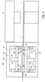
- 2 1 shows a device 19 which is connected upstream of the punching device 4 and has two application units 8 which are arranged in the area above and below the electrical strip 1 .
- the device has a portal-shaped frame 20 in which two receiving spaces 21, 22 lying one above the other are provided, in each of which an application unit 8 is accommodated.
- the frame 20 has two mutually parallel vertical uprights 24, 25 which are connected to one another at the upper end by a cross member 26.
- the stands 24, 25 can be connected to one another at the lower end by a further cross member 27.
- inlet opening 28 In stand 24 there is a schematically represented inlet opening 28 and in stand 25 there is a schematically represented outlet opening 29 for the electrical steel strip 1 to pass through.
- the rails 34 to 37 extend parallel to the electrical strip 1.
- a valve plate 38 is mounted on the rails 34, 35 and can be moved horizontally along the rails 34, 35 transversely to the feed direction of the electrical strip 1.
- the valve plate 38 carries the valve 9 with the valve tappet (not shown).
- the valve plate 38 is advantageously mounted on the rails 34, 35 with the interposition of at least one spring element 39, 40 as a decoupling element.
- the valve 9 can advantageously be adjusted in the height direction relative to the valve plate 38 in order to be able to set the distance between the valve 9 and the electrical strip 1 .
- valve plate 41 On the rails 36, 37 in the lower receiving space 22, a valve plate 41 is also mounted.
- the valve plate 41 is also advantageously located on the rails 36, 37 with at least one spring element 42, 43 as a decoupling element in each case.
- the valve plate 41 carries the valve 9, which is mounted in the valve plate 41 so that it can be adjusted in the height direction.
- the two valve plates 38, 41 with the valve 9 are arranged as mirror images of one another.
- the adhesive can be applied to the top and bottom of the electrical strip 1 with the two application units 8 .
- the position of the drops of adhesive 13 on the electrical strip 1 can be determined by moving the valve plate 38 , 41 .
- Both application units 8 are advantageously of the same design. In principle, the application units 8 can also have a different configuration.
- the two application units 8 have, as shown in the 1 and according to the form figure 5 has been explained, in each case at least one radiation source 15 in order to activate the adhesive with light of the required wavelength before it is applied to the electrical strip 1.
- the electrical strip 1 provided with the drops of adhesive 13 then reaches the punching device 4, with which laminations are punched out of the electrical strip 1 in a known manner.
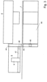
- the stand 44 is a vertical stand.
- a schematically illustrated inlet opening 45 for the passage of electrical steel 1 is located in it.
- a valve plate 47 is mounted on stand 44 and can be moved horizontally along rails 46 transversely to the feed direction of electrical steel 1 .
- the rails 46 are fastened to a lower tool part 49 of the punching device 4 and extend parallel to the electrical strip 1.
- the valve plate 47 carries the valve 9 with the valve tappet (not shown).
- the valve plate 47 is advantageously mounted on the stand 44 with the interposition of at least one spring element 48 as a decoupling element.
- the valve 9 can advantageously be adjusted in the height direction relative to the valve plate 47 in order to be able to set the distance between the valve 9 and the electrical strip 1 .
- the adhesive can be applied to the upper side of the electrical strip 1 with at least one application unit 8 .
- the position of the drops of adhesive 13 on the electrical strip 1 can be determined by moving the valve plate 47 .
- the application unit 8 is only provided in the area above the electrical steel strip 1 . It has at least one radiation source 15 ( 1 and 5 ) to activate the adhesive in the manner described.
Landscapes
- Engineering & Computer Science (AREA)
- Manufacturing & Machinery (AREA)
- Power Engineering (AREA)
- Chemical & Material Sciences (AREA)
- Organic Chemistry (AREA)
- Physics & Mathematics (AREA)
- Plasma & Fusion (AREA)
- Coating Apparatus (AREA)
- Manufacture Of Motors, Generators (AREA)
- Adhesives Or Adhesive Processes (AREA)
- Application Of Or Painting With Fluid Materials (AREA)
- Manufacturing Optical Record Carriers (AREA)
Claims (9)
- Procédé de fabrication de paquets de lamelles pour des rotors et/ou des stators de moteurs électriques ou de générateurs, dans lequel des lamelles sont estampées à partir d'un feuillard électrique au moyen d'un outil d'estampage (6) placé dans un dispositif d'estampage (4), dans lequel le dispositif d'estampage (4) est raccordé à une commande (7) permettant de commander la course d'estampage, dans lequel un agent adhésif est appliqué sur au moins un côté de la lamelle et les lamelles sont empilées en un paquet de lamelles, dans lequel l'agent adhésif est alimenté vers un poussoir de soupape (12) d'une soupape (9) d'une unité d'application (8) à partir d'un récipient de stockage par le biais d'une conduite d'amenée (14), dans lequel l'agent adhésif est appliqué à l'aide du poussoir de soupape et dans lequel la conduite d'amenée (14) s'étend jusqu'au poussoir de soupape, dans lequel les lamelles superposées dans la pile de lamelles sont reliées entre elles par l'agent adhésif,
caractérisé en ce qu'un agent adhésif activable par une lumière d'une longueur d'onde requise provenant d'une source de rayonnement est utilisé en tant qu'agent adhésif, dans lequel l'agent adhésif est irradié avec cette lumière et activé avec cette lumière immédiatement avant la sortie hors de l'unité d'application (8), dans lequel la source de rayonnement (15) est configurée avec un trajet d'exposition (16) maximal par rapport à la direction longitudinale de la conduite d'amenée (14), dans lequel la conduite d'amenée (14) est transparente au rayonnement émis par la source de rayonnement (15) dans la région de ce trajet d'exposition (16), dans lequel le trajet d'exposition (16) peut être raccourci en plaçant un écran (17) entre la conduite d'amenée (14) et la source de rayonnement (15), lequel est opaque au rayonnement émis par la source de rayonnement (15), de sorte que le rayonnement n'atteint l'agent adhésif que dans la région non recouverte par l'écran (17), l'écran (17) étant réglable. - Procédé selon la revendication 1, destiné à fabriquer un paquet de lamelles d'un rotor,
caractérisé en ce qu'une activation de colle est réalisée pour la fixation d'aimants sur le rotor. - Procédé selon la revendication 1 ou 2,
caractérisé en ce que l'agent adhésif consistant avantageusement en une colle UV est appliqué sous forme de gouttes (13). - Procédé selon l'une des revendications 1 à 3,
caractérisé en ce que l'agent adhésif est appliqué sans contact. - Procédé selon l'une des revendications 1 à 4,
caractérisé en ce que l'agent adhésif est appliqué avant ou après l'opération d'estampage. - Procédé selon l'une des revendications 1 à 5,
caractérisé en ce que la durée d'irradiation dépend du nombre de courses de l'outil d'estampage (6). - Procédé selon l'une des revendications 1 à 6,
caractérisé en ce qu'un traitement au plasma permet de régler l'énergie de surface et d'activer la surface des lamelles. - Procédé selon l'une des revendications 1 à 7, destiné à fabriquer un paquet de lamelles d'un rotor,
caractérisé en ce que des aimants sont fixés sur le paquet de lamelles prévu pour des rotors au moyen de l'agent adhésif introduit avant ou après le collage des aimants. - Procédé selon la revendication 8,
caractérisé en ce que la durée d'irradiation dépend du temps de collage ou du temps d'ouverture de colle des aimants.
Priority Applications (3)
| Application Number | Priority Date | Filing Date | Title |
|---|---|---|---|
| EP22215713.3A EP4216409A1 (fr) | 2018-04-23 | 2019-04-17 | Procédé de fabrication de paquets de lamelles ainsi que dispositif d'application pour un adhésif pour la mise en oeuvre du procédé |
| RS20230674A RS66627B1 (sr) | 2018-04-23 | 2019-04-17 | Postupak za proizvodnju paketa lamele i aplikatora za lepak za izvođenje postupka |
| SI201930618T SI3562007T1 (sl) | 2018-04-23 | 2019-04-17 | Postopek za izdelavo paketov lamel in pa nanašalna priprava za lepilo za izvedbo postopka |
Applications Claiming Priority (1)
| Application Number | Priority Date | Filing Date | Title |
|---|---|---|---|
| DE102018003345.8A DE102018003345A1 (de) | 2018-04-23 | 2018-04-23 | Verfahren zur Herstellung von Lamellenpaketen sowie Auftrageinrichtung für ein Klebemittel zur Durchführung des Verfahrens |
Related Child Applications (3)
| Application Number | Title | Priority Date | Filing Date |
|---|---|---|---|
| EP22215713.3A Division-Into EP4216409A1 (fr) | 2018-04-23 | 2019-04-17 | Procédé de fabrication de paquets de lamelles ainsi que dispositif d'application pour un adhésif pour la mise en oeuvre du procédé |
| EP22215713.3A Division EP4216409A1 (fr) | 2018-04-23 | 2019-04-17 | Procédé de fabrication de paquets de lamelles ainsi que dispositif d'application pour un adhésif pour la mise en oeuvre du procédé |
| EP22215713.3A Previously-Filed-Application EP4216409A1 (fr) | 2018-04-23 | 2019-04-17 | Procédé de fabrication de paquets de lamelles ainsi que dispositif d'application pour un adhésif pour la mise en oeuvre du procédé |
Publications (2)
| Publication Number | Publication Date |
|---|---|
| EP3562007A1 EP3562007A1 (fr) | 2019-10-30 |
| EP3562007B1 true EP3562007B1 (fr) | 2023-06-07 |
Family
ID=66239727
Family Applications (2)
| Application Number | Title | Priority Date | Filing Date |
|---|---|---|---|
| EP22215713.3A Pending EP4216409A1 (fr) | 2018-04-23 | 2019-04-17 | Procédé de fabrication de paquets de lamelles ainsi que dispositif d'application pour un adhésif pour la mise en oeuvre du procédé |
| EP19000189.1A Active EP3562007B1 (fr) | 2018-04-23 | 2019-04-17 | Procédé de fabrication de paquets de lamelles ainsi que dispositif d'application pour un agent adhésif permettant la mise en oeuvre dudit procédé |
Family Applications Before (1)
| Application Number | Title | Priority Date | Filing Date |
|---|---|---|---|
| EP22215713.3A Pending EP4216409A1 (fr) | 2018-04-23 | 2019-04-17 | Procédé de fabrication de paquets de lamelles ainsi que dispositif d'application pour un adhésif pour la mise en oeuvre du procédé |
Country Status (12)
| Country | Link |
|---|---|
| US (2) | US11535021B2 (fr) |
| EP (2) | EP4216409A1 (fr) |
| JP (1) | JP7377620B2 (fr) |
| CN (1) | CN110385233A (fr) |
| CA (1) | CA3040951A1 (fr) |
| DE (1) | DE102018003345A1 (fr) |
| ES (1) | ES2955942T3 (fr) |
| HU (1) | HUE064439T2 (fr) |
| MX (1) | MX2019004643A (fr) |
| PL (1) | PL3562007T3 (fr) |
| RS (1) | RS66627B1 (fr) |
| SI (1) | SI3562007T1 (fr) |
Families Citing this family (3)
| Publication number | Priority date | Publication date | Assignee | Title |
|---|---|---|---|---|
| DE102018110951A1 (de) * | 2017-11-03 | 2019-05-09 | Fraunhofer-Gesellschaft zur Förderung der angewandten Forschung eingetragener Verein | Verfahren zum klebtechnischen Verbinden von Elektroblechen und Elektrobleche hergestellt nach einem entsprechenden Verfahren |
| EP4470677A1 (fr) | 2022-01-24 | 2024-12-04 | Eurogroup Laminations S.p.A. | Méthode et appareil pour l'application de particules ayant des tailles commandées de revêtements liquides sur des tôles laminées à géométries variables |
| DE102024001492A1 (de) * | 2024-05-05 | 2025-11-06 | Feintool International Holding Ag | Verfahren zur Herstellung von Lamellenpaketen aus aufeinander liegenden Lamellen sowie Anlage zur Durchführung eines solchen Verfahrens |
Family Cites Families (20)
| Publication number | Priority date | Publication date | Assignee | Title |
|---|---|---|---|---|
| DE19936730A1 (de) * | 1999-08-06 | 2001-02-22 | Sca Schucker Gmbh | Vorrichtung und Verfahren zum Aufbringen eines Kunststoffstrangs auf eine Unterlage |
| US6737784B2 (en) * | 2000-10-16 | 2004-05-18 | Scott M. Lindquist | Laminated amorphous metal component for an electric machine |
| DE10216098A1 (de) * | 2002-04-12 | 2003-10-23 | Bosch Gmbh Robert | Rotor für eine elektrische Maschine |
| JP2007501110A (ja) * | 2003-08-04 | 2007-01-25 | チバ スペシャルティ ケミカルズ ホールディング インコーポレーテッド | 強く付着しているコーティングの製造方法 |
| FR2872068B1 (fr) * | 2004-06-28 | 2006-10-27 | Centre Nat Rech Scient Cnrse | Procede et dispositif pour le depot de couches minces par pulverisation electrohydrodynamique, notamment en post-decharge |
| US20060066168A1 (en) * | 2004-09-30 | 2006-03-30 | Shoykhet Boris A | Bonded rotor laminations |
| US7517561B2 (en) * | 2005-09-21 | 2009-04-14 | Ford Global Technologies, Llc | Method of coating a substrate for adhesive bonding |
| JP2007160926A (ja) | 2005-11-18 | 2007-06-28 | Seiko Epson Corp | 液滴吐出装置 |
| MX2007002769A (es) | 2006-03-10 | 2008-11-14 | Kienle & Spiess Stanz & Druck | Método y aparato para producir pilas de láminas, y paquete de láminas. |
| JP4687747B2 (ja) * | 2007-06-18 | 2011-05-25 | セイコーエプソン株式会社 | 接合方法 |
| US20130162064A1 (en) * | 2011-12-22 | 2013-06-27 | Samsung Electro-Mechanics Co., Ltd. | Laminated core and method for manufacturing the same |
| DE102012001744A1 (de) * | 2012-01-28 | 2013-08-01 | Volkswagen Aktiengesellschaft | Verfahren, Vorrichtung und Klebstoff zur Herstellung eines Blechpakets aus mehreren aufeinander gestapelten Elektroblechen |
| EP2828001A1 (fr) * | 2012-03-22 | 2015-01-28 | Basf Se | Procédé et dispositif de production de couches de peinture durcies |
| JP6275589B2 (ja) | 2013-09-26 | 2018-02-07 | 芝浦メカトロニクス株式会社 | 接着剤塗布装置、接着剤塗布方法、表示装置用部材の製造装置及び表示装置用部材の製造方法 |
| DE102014000690A1 (de) | 2014-01-17 | 2015-07-23 | Kienle + Spiess Gmbh | Ringförmiges Lamellenpaket aus Einzelzahnpaketen sowie Verfahren zur Herstellung eines Lamellenpaketes |
| US10201844B2 (en) * | 2014-11-07 | 2019-02-12 | Kuroda Precision Industries Ltd. | Apparatus and method for manufacturing laminated iron core |
| DE102014017149A1 (de) | 2014-11-17 | 2016-05-19 | Kienle + Spiess Gmbh | Verfahren zur Herstellung von Lamellenpaketen und Anlage zur Durchführung des Verfahrens |
| JP2016140134A (ja) * | 2015-01-26 | 2016-08-04 | アイシン・エィ・ダブリュ株式会社 | モータコアおよびモータコアの製造方法 |
| DE102015225758A1 (de) * | 2015-12-17 | 2017-06-22 | Robert Bosch Gmbh | Verfahren zum Beschichten eines elektromagnetisch erregbaren Kerns |
| WO2017199527A1 (fr) | 2016-05-20 | 2017-11-23 | 日本電産株式会社 | Procédé de fabrication de noyau de stator |
-
2018
- 2018-04-23 DE DE102018003345.8A patent/DE102018003345A1/de active Pending
-
2019
- 2019-04-17 RS RS20230674A patent/RS66627B1/sr unknown
- 2019-04-17 PL PL19000189.1T patent/PL3562007T3/pl unknown
- 2019-04-17 EP EP22215713.3A patent/EP4216409A1/fr active Pending
- 2019-04-17 EP EP19000189.1A patent/EP3562007B1/fr active Active
- 2019-04-17 HU HUE19000189A patent/HUE064439T2/hu unknown
- 2019-04-17 SI SI201930618T patent/SI3562007T1/sl unknown
- 2019-04-17 ES ES19000189T patent/ES2955942T3/es active Active
- 2019-04-22 MX MX2019004643A patent/MX2019004643A/es unknown
- 2019-04-22 JP JP2019080862A patent/JP7377620B2/ja active Active
- 2019-04-23 US US16/391,475 patent/US11535021B2/en active Active
- 2019-04-23 CA CA3040951A patent/CA3040951A1/fr active Pending
- 2019-04-23 CN CN201910325769.3A patent/CN110385233A/zh active Pending
-
2022
- 2022-11-27 US US17/994,331 patent/US12447729B2/en active Active
Also Published As
| Publication number | Publication date |
|---|---|
| US11535021B2 (en) | 2022-12-27 |
| DE102018003345A1 (de) | 2019-10-24 |
| EP3562007A1 (fr) | 2019-10-30 |
| JP7377620B2 (ja) | 2023-11-10 |
| HUE064439T2 (hu) | 2024-03-28 |
| PL3562007T3 (pl) | 2024-05-06 |
| US20190322093A1 (en) | 2019-10-24 |
| CN110385233A (zh) | 2019-10-29 |
| SI3562007T1 (sl) | 2024-05-31 |
| RS66627B1 (sr) | 2025-04-30 |
| CA3040951A1 (fr) | 2019-10-23 |
| MX2019004643A (es) | 2019-11-08 |
| ES2955942T3 (es) | 2023-12-11 |
| US12447729B2 (en) | 2025-10-21 |
| US20230089960A1 (en) | 2023-03-23 |
| EP4216409A1 (fr) | 2023-07-26 |
| JP2019193561A (ja) | 2019-10-31 |
| BR102019007941A2 (pt) | 2019-11-26 |
Similar Documents
| Publication | Publication Date | Title |
|---|---|---|
| EP2826136B1 (fr) | Paquet de tôles et procédé pour le produire | |
| DE3247344C2 (fr) | ||
| EP3021466B1 (fr) | Procede de fabrication de paquets de lamelles et installation d'execution du procede | |
| EP3562007B1 (fr) | Procédé de fabrication de paquets de lamelles ainsi que dispositif d'application pour un agent adhésif permettant la mise en oeuvre dudit procédé | |
| EP2189057B1 (fr) | Procédé de fabrication de tuyaux d'irrigation goutte à goutte | |
| EP1833145B1 (fr) | Procédé, outil et dispositif destinés à la production de paquets de tôles et un paquet de tôles | |
| EP3078103B1 (fr) | Procédé de fabrication de tôles destinées à constituer un noyau feuilleté, en particulier pour des moteurs et générateurs électriques, dispositif comprenant au moins une presse de découpage ainsi que tôle et noyau feuilleté réalisés selon ledit procédé | |
| EP3495280B1 (fr) | Dispositif d'étiquetage avec ensemble de poussée | |
| DE112019005954T5 (de) | Schichtkernherstellungsverfahren, Klebstoffauftragseinrichtung und Schichtkernherstellungsapparat | |
| DE2942997A1 (de) | Loetmetallpackung und herstellungsverfahren fuer diese | |
| EP4511954A1 (fr) | Procédé et dispositif de production de noyaux feuilletés à partir de tôles | |
| WO2018033248A2 (fr) | Procédé de montage de puces semi-conductrices et dispositif de transfert de puces semi-conductrices | |
| EP1529648A1 (fr) | Procédé pour produire des supports d'information, par exemple des cartes, et installation de sa réalisation | |
| DE3332992A1 (de) | Drucker mit mosaikdruckkoepfen | |
| DE102016013317B4 (de) | Verfahren zum Herstellen eines dreidimensionalen Formgegenstands und Vorrichtung zur Durchführung des Verfahrens | |
| DE3783624T2 (de) | Programmierbarer, mit magnetischer abstossung arbeitender stanzapparat. | |
| EP2964447B1 (fr) | Procédé de dépôt d'un revêtement sur des pièces et dispositif de revêtement de pièces | |
| EP2213475A2 (fr) | Dispositif d'estampage et procédé | |
| DE102004059889B4 (de) | Vorrichtung und Verfahren zum Wickeln eines Scheibenläufers für einen Scheibenläufermotor | |
| WO2014202246A1 (fr) | Dispositif et procédé permettant d'amener des alaises de chants | |
| EP2004418A2 (fr) | Dispositif pour relier des piles constituees d'elements plats | |
| EP4648267A1 (fr) | Procédé de fabrication de paquets de lamelles à partir de lamelles superposées et installation pour la mise en oeuvre d'un tel procédé | |
| DE102020107332A1 (de) | Faserspule und Wickelvorrichtung zum Wickeln einer Faserspule | |
| DE102023206353A1 (de) | Kleben von Lamellenpaketen mit LIFT-Technologie | |
| DE102023206352A1 (de) | Kleben von Lamellenpaketen mit 2K-Klebstoffen in Inkjet-Technologie |
Legal Events
| Date | Code | Title | Description |
|---|---|---|---|
| PUAI | Public reference made under article 153(3) epc to a published international application that has entered the european phase |
Free format text: ORIGINAL CODE: 0009012 |
|
| STAA | Information on the status of an ep patent application or granted ep patent |
Free format text: STATUS: THE APPLICATION HAS BEEN PUBLISHED |
|
| AK | Designated contracting states |
Kind code of ref document: A1 Designated state(s): AL AT BE BG CH CY CZ DE DK EE ES FI FR GB GR HR HU IE IS IT LI LT LU LV MC MK MT NL NO PL PT RO RS SE SI SK SM TR |
|
| AX | Request for extension of the european patent |
Extension state: BA ME |
|
| STAA | Information on the status of an ep patent application or granted ep patent |
Free format text: STATUS: REQUEST FOR EXAMINATION WAS MADE |
|
| 17P | Request for examination filed |
Effective date: 20200430 |
|
| RBV | Designated contracting states (corrected) |
Designated state(s): AL AT BE BG CH CY CZ DE DK EE ES FI FR GB GR HR HU IE IS IT LI LT LU LV MC MK MT NL NO PL PT RO RS SE SI SK SM TR |
|
| STAA | Information on the status of an ep patent application or granted ep patent |
Free format text: STATUS: EXAMINATION IS IN PROGRESS |
|
| 17Q | First examination report despatched |
Effective date: 20200702 |
|
| GRAP | Despatch of communication of intention to grant a patent |
Free format text: ORIGINAL CODE: EPIDOSNIGR1 |
|
| STAA | Information on the status of an ep patent application or granted ep patent |
Free format text: STATUS: GRANT OF PATENT IS INTENDED |
|
| INTG | Intention to grant announced |
Effective date: 20221129 |
|
| GRAS | Grant fee paid |
Free format text: ORIGINAL CODE: EPIDOSNIGR3 |
|
| GRAA | (expected) grant |
Free format text: ORIGINAL CODE: 0009210 |
|
| STAA | Information on the status of an ep patent application or granted ep patent |
Free format text: STATUS: THE PATENT HAS BEEN GRANTED |
|
| AK | Designated contracting states |
Kind code of ref document: B1 Designated state(s): AL AT BE BG CH CY CZ DE DK EE ES FI FR GB GR HR HU IE IS IT LI LT LU LV MC MK MT NL NO PL PT RO RS SE SI SK SM TR |
|
| REG | Reference to a national code |
Ref country code: GB Ref legal event code: FG4D Free format text: NOT ENGLISH |
|
| REG | Reference to a national code |
Ref country code: CH Ref legal event code: EP Ref country code: AT Ref legal event code: REF Ref document number: 1577831 Country of ref document: AT Kind code of ref document: T Effective date: 20230615 Ref country code: DE Ref legal event code: R096 Ref document number: 502019007834 Country of ref document: DE |
|
| REG | Reference to a national code |
Ref country code: NL Ref legal event code: FP |
|
| REG | Reference to a national code |
Ref country code: LT Ref legal event code: MG9D |
|
| REG | Reference to a national code |
Ref country code: DE Ref legal event code: R081 Ref document number: 502019007834 Country of ref document: DE Owner name: FEINTOOL INTERNATIONAL HOLDING AG, CH Free format text: FORMER OWNER: KIENLE + SPIESS GMBH, 74343 SACHSENHEIM, DE |
|
| PG25 | Lapsed in a contracting state [announced via postgrant information from national office to epo] |
Ref country code: SE Free format text: LAPSE BECAUSE OF FAILURE TO SUBMIT A TRANSLATION OF THE DESCRIPTION OR TO PAY THE FEE WITHIN THE PRESCRIBED TIME-LIMIT Effective date: 20230607 Ref country code: NO Free format text: LAPSE BECAUSE OF FAILURE TO SUBMIT A TRANSLATION OF THE DESCRIPTION OR TO PAY THE FEE WITHIN THE PRESCRIBED TIME-LIMIT Effective date: 20230907 |
|
| REG | Reference to a national code |
Ref country code: NL Ref legal event code: PD Owner name: FEINTOOL INTERNATIONAL HOLDING AG; CH Free format text: DETAILS ASSIGNMENT: CHANGE OF OWNER(S), ASSIGNMENT; FORMER OWNER NAME: KIENLE + SPIESS GMBH Effective date: 20231024 |
|
| RAP2 | Party data changed (patent owner data changed or rights of a patent transferred) |
Owner name: FEINTOOL INTERNATIONAL HOLDING AG |
|
| PG25 | Lapsed in a contracting state [announced via postgrant information from national office to epo] |
Ref country code: LV Free format text: LAPSE BECAUSE OF FAILURE TO SUBMIT A TRANSLATION OF THE DESCRIPTION OR TO PAY THE FEE WITHIN THE PRESCRIBED TIME-LIMIT Effective date: 20230607 Ref country code: LT Free format text: LAPSE BECAUSE OF FAILURE TO SUBMIT A TRANSLATION OF THE DESCRIPTION OR TO PAY THE FEE WITHIN THE PRESCRIBED TIME-LIMIT Effective date: 20230607 Ref country code: HR Free format text: LAPSE BECAUSE OF FAILURE TO SUBMIT A TRANSLATION OF THE DESCRIPTION OR TO PAY THE FEE WITHIN THE PRESCRIBED TIME-LIMIT Effective date: 20230607 Ref country code: GR Free format text: LAPSE BECAUSE OF FAILURE TO SUBMIT A TRANSLATION OF THE DESCRIPTION OR TO PAY THE FEE WITHIN THE PRESCRIBED TIME-LIMIT Effective date: 20230908 |
|
| REG | Reference to a national code |
Ref country code: ES Ref legal event code: FG2A Ref document number: 2955942 Country of ref document: ES Kind code of ref document: T3 Effective date: 20231211 |
|
| PG25 | Lapsed in a contracting state [announced via postgrant information from national office to epo] |
Ref country code: FI Free format text: LAPSE BECAUSE OF FAILURE TO SUBMIT A TRANSLATION OF THE DESCRIPTION OR TO PAY THE FEE WITHIN THE PRESCRIBED TIME-LIMIT Effective date: 20230607 |
|
| PG25 | Lapsed in a contracting state [announced via postgrant information from national office to epo] |
Ref country code: SK Free format text: LAPSE BECAUSE OF FAILURE TO SUBMIT A TRANSLATION OF THE DESCRIPTION OR TO PAY THE FEE WITHIN THE PRESCRIBED TIME-LIMIT Effective date: 20230607 |
|
| PG25 | Lapsed in a contracting state [announced via postgrant information from national office to epo] |
Ref country code: IS Free format text: LAPSE BECAUSE OF FAILURE TO SUBMIT A TRANSLATION OF THE DESCRIPTION OR TO PAY THE FEE WITHIN THE PRESCRIBED TIME-LIMIT Effective date: 20231007 |
|
| PG25 | Lapsed in a contracting state [announced via postgrant information from national office to epo] |
Ref country code: SM Free format text: LAPSE BECAUSE OF FAILURE TO SUBMIT A TRANSLATION OF THE DESCRIPTION OR TO PAY THE FEE WITHIN THE PRESCRIBED TIME-LIMIT Effective date: 20230607 Ref country code: SK Free format text: LAPSE BECAUSE OF FAILURE TO SUBMIT A TRANSLATION OF THE DESCRIPTION OR TO PAY THE FEE WITHIN THE PRESCRIBED TIME-LIMIT Effective date: 20230607 Ref country code: PT Free format text: LAPSE BECAUSE OF FAILURE TO SUBMIT A TRANSLATION OF THE DESCRIPTION OR TO PAY THE FEE WITHIN THE PRESCRIBED TIME-LIMIT Effective date: 20231009 Ref country code: IS Free format text: LAPSE BECAUSE OF FAILURE TO SUBMIT A TRANSLATION OF THE DESCRIPTION OR TO PAY THE FEE WITHIN THE PRESCRIBED TIME-LIMIT Effective date: 20231007 Ref country code: EE Free format text: LAPSE BECAUSE OF FAILURE TO SUBMIT A TRANSLATION OF THE DESCRIPTION OR TO PAY THE FEE WITHIN THE PRESCRIBED TIME-LIMIT Effective date: 20230607 |
|
| REG | Reference to a national code |
Ref country code: DE Ref legal event code: R097 Ref document number: 502019007834 Country of ref document: DE |
|
| REG | Reference to a national code |
Ref country code: AT Ref legal event code: PC Ref document number: 1577831 Country of ref document: AT Kind code of ref document: T Owner name: FEINTOOL INTERNATIONAL HOLDING AG, CH Effective date: 20240122 |
|
| REG | Reference to a national code |
Ref country code: HU Ref legal event code: AG4A Ref document number: E064439 Country of ref document: HU |
|
| REG | Reference to a national code |
Ref country code: GB Ref legal event code: 732E Free format text: REGISTERED BETWEEN 20240307 AND 20240313 |
|
| PLBE | No opposition filed within time limit |
Free format text: ORIGINAL CODE: 0009261 |
|
| STAA | Information on the status of an ep patent application or granted ep patent |
Free format text: STATUS: NO OPPOSITION FILED WITHIN TIME LIMIT |
|
| PG25 | Lapsed in a contracting state [announced via postgrant information from national office to epo] |
Ref country code: DK Free format text: LAPSE BECAUSE OF FAILURE TO SUBMIT A TRANSLATION OF THE DESCRIPTION OR TO PAY THE FEE WITHIN THE PRESCRIBED TIME-LIMIT Effective date: 20230607 |
|
| 26N | No opposition filed |
Effective date: 20240308 |
|
| PG25 | Lapsed in a contracting state [announced via postgrant information from national office to epo] |
Ref country code: BG Free format text: LAPSE BECAUSE OF FAILURE TO SUBMIT A TRANSLATION OF THE DESCRIPTION OR TO PAY THE FEE WITHIN THE PRESCRIBED TIME-LIMIT Effective date: 20230607 |
|
| PG25 | Lapsed in a contracting state [announced via postgrant information from national office to epo] |
Ref country code: MC Free format text: LAPSE BECAUSE OF FAILURE TO SUBMIT A TRANSLATION OF THE DESCRIPTION OR TO PAY THE FEE WITHIN THE PRESCRIBED TIME-LIMIT Effective date: 20230607 |
|
| PG25 | Lapsed in a contracting state [announced via postgrant information from national office to epo] |
Ref country code: MC Free format text: LAPSE BECAUSE OF FAILURE TO SUBMIT A TRANSLATION OF THE DESCRIPTION OR TO PAY THE FEE WITHIN THE PRESCRIBED TIME-LIMIT Effective date: 20230607 Ref country code: BG Free format text: LAPSE BECAUSE OF FAILURE TO SUBMIT A TRANSLATION OF THE DESCRIPTION OR TO PAY THE FEE WITHIN THE PRESCRIBED TIME-LIMIT Effective date: 20230607 |
|
| PG25 | Lapsed in a contracting state [announced via postgrant information from national office to epo] |
Ref country code: LU Free format text: LAPSE BECAUSE OF NON-PAYMENT OF DUE FEES Effective date: 20240417 |
|
| REG | Reference to a national code |
Ref country code: BE Ref legal event code: MM Effective date: 20240430 |
|
| PG25 | Lapsed in a contracting state [announced via postgrant information from national office to epo] |
Ref country code: LU Free format text: LAPSE BECAUSE OF NON-PAYMENT OF DUE FEES Effective date: 20240417 |
|
| PG25 | Lapsed in a contracting state [announced via postgrant information from national office to epo] |
Ref country code: BE Free format text: LAPSE BECAUSE OF NON-PAYMENT OF DUE FEES Effective date: 20240430 |
|
| PG25 | Lapsed in a contracting state [announced via postgrant information from national office to epo] |
Ref country code: BE Free format text: LAPSE BECAUSE OF NON-PAYMENT OF DUE FEES Effective date: 20240430 |
|
| PG25 | Lapsed in a contracting state [announced via postgrant information from national office to epo] |
Ref country code: IE Free format text: LAPSE BECAUSE OF NON-PAYMENT OF DUE FEES Effective date: 20240417 |
|
| PGFP | Annual fee paid to national office [announced via postgrant information from national office to epo] |
Ref country code: SI Payment date: 20250317 Year of fee payment: 7 |
|
| PGFP | Annual fee paid to national office [announced via postgrant information from national office to epo] |
Ref country code: PL Payment date: 20250317 Year of fee payment: 7 Ref country code: FR Payment date: 20250321 Year of fee payment: 7 Ref country code: CZ Payment date: 20250317 Year of fee payment: 7 |
|
| PGFP | Annual fee paid to national office [announced via postgrant information from national office to epo] |
Ref country code: GB Payment date: 20250321 Year of fee payment: 7 |
|
| PGFP | Annual fee paid to national office [announced via postgrant information from national office to epo] |
Ref country code: RS Payment date: 20250317 Year of fee payment: 7 |
|
| PGFP | Annual fee paid to national office [announced via postgrant information from national office to epo] |
Ref country code: TR Payment date: 20250325 Year of fee payment: 7 |
|
| PGFP | Annual fee paid to national office [announced via postgrant information from national office to epo] |
Ref country code: NL Payment date: 20250423 Year of fee payment: 7 |
|
| PGFP | Annual fee paid to national office [announced via postgrant information from national office to epo] |
Ref country code: DE Payment date: 20250626 Year of fee payment: 7 |
|
| PGFP | Annual fee paid to national office [announced via postgrant information from national office to epo] |
Ref country code: ES Payment date: 20250506 Year of fee payment: 7 |
|
| PGFP | Annual fee paid to national office [announced via postgrant information from national office to epo] |
Ref country code: HU Payment date: 20250430 Year of fee payment: 7 |
|
| PGFP | Annual fee paid to national office [announced via postgrant information from national office to epo] |
Ref country code: IT Payment date: 20250327 Year of fee payment: 7 |
|
| PGFP | Annual fee paid to national office [announced via postgrant information from national office to epo] |
Ref country code: CH Payment date: 20250501 Year of fee payment: 7 |
|
| PGFP | Annual fee paid to national office [announced via postgrant information from national office to epo] |
Ref country code: RO Payment date: 20250416 Year of fee payment: 7 Ref country code: AT Payment date: 20250414 Year of fee payment: 7 |
|
| PG25 | Lapsed in a contracting state [announced via postgrant information from national office to epo] |
Ref country code: CY Free format text: LAPSE BECAUSE OF FAILURE TO SUBMIT A TRANSLATION OF THE DESCRIPTION OR TO PAY THE FEE WITHIN THE PRESCRIBED TIME-LIMIT; INVALID AB INITIO Effective date: 20190417 |