EP3622146B1 - Chariot de guidage pour le montage mobile d'un élément de meuble - Google Patents
Chariot de guidage pour le montage mobile d'un élément de meuble Download PDFInfo
- Publication number
- EP3622146B1 EP3622146B1 EP18732627.7A EP18732627A EP3622146B1 EP 3622146 B1 EP3622146 B1 EP 3622146B1 EP 18732627 A EP18732627 A EP 18732627A EP 3622146 B1 EP3622146 B1 EP 3622146B1
- Authority
- EP
- European Patent Office
- Prior art keywords
- chassis
- connecting portion
- guide carriage
- relative
- positioning device
- Prior art date
- Legal status (The legal status is an assumption and is not a legal conclusion. Google has not performed a legal analysis and makes no representation as to the accuracy of the status listed.)
- Active
Links
Images




Classifications
-
- E—FIXED CONSTRUCTIONS
- E05—LOCKS; KEYS; WINDOW OR DOOR FITTINGS; SAFES
- E05D—HINGES OR SUSPENSION DEVICES FOR DOORS, WINDOWS OR WINGS
- E05D15/00—Suspension arrangements for wings
- E05D15/06—Suspension arrangements for wings for wings sliding horizontally more or less in their own plane
- E05D15/0621—Details, e.g. suspension or supporting guides
- E05D15/0626—Details, e.g. suspension or supporting guides for wings suspended at the top
- E05D15/063—Details, e.g. suspension or supporting guides for wings suspended at the top on wheels with fixed axis
- E05D15/0634—Details, e.g. suspension or supporting guides for wings suspended at the top on wheels with fixed axis with height adjustment
-
- E—FIXED CONSTRUCTIONS
- E05—LOCKS; KEYS; WINDOW OR DOOR FITTINGS; SAFES
- E05D—HINGES OR SUSPENSION DEVICES FOR DOORS, WINDOWS OR WINGS
- E05D15/00—Suspension arrangements for wings
- E05D15/26—Suspension arrangements for wings for folding wings
- E05D15/264—Suspension arrangements for wings for folding wings for bi-fold wings
- E05D15/266—Suspension arrangements for wings for folding wings for bi-fold wings comprising two pivots placed at opposite edges of the wing
-
- E—FIXED CONSTRUCTIONS
- E05—LOCKS; KEYS; WINDOW OR DOOR FITTINGS; SAFES
- E05D—HINGES OR SUSPENSION DEVICES FOR DOORS, WINDOWS OR WINGS
- E05D15/00—Suspension arrangements for wings
- E05D15/06—Suspension arrangements for wings for wings sliding horizontally more or less in their own plane
- E05D15/0621—Details, e.g. suspension or supporting guides
- E05D15/0626—Details, e.g. suspension or supporting guides for wings suspended at the top
- E05D15/063—Details, e.g. suspension or supporting guides for wings suspended at the top on wheels with fixed axis
-
- E—FIXED CONSTRUCTIONS
- E05—LOCKS; KEYS; WINDOW OR DOOR FITTINGS; SAFES
- E05D—HINGES OR SUSPENSION DEVICES FOR DOORS, WINDOWS OR WINGS
- E05D15/00—Suspension arrangements for wings
- E05D15/26—Suspension arrangements for wings for folding wings
-
- E—FIXED CONSTRUCTIONS
- E05—LOCKS; KEYS; WINDOW OR DOOR FITTINGS; SAFES
- E05D—HINGES OR SUSPENSION DEVICES FOR DOORS, WINDOWS OR WINGS
- E05D15/00—Suspension arrangements for wings
- E05D15/56—Suspension arrangements for wings with successive different movements
- E05D15/58—Suspension arrangements for wings with successive different movements with both swinging and sliding movements
-
- E—FIXED CONSTRUCTIONS
- E05—LOCKS; KEYS; WINDOW OR DOOR FITTINGS; SAFES
- E05Y—INDEXING SCHEME ASSOCIATED WITH SUBCLASSES E05D AND E05F, RELATING TO CONSTRUCTION ELEMENTS, ELECTRIC CONTROL, POWER SUPPLY, POWER SIGNAL OR TRANSMISSION, USER INTERFACES, MOUNTING OR COUPLING, DETAILS, ACCESSORIES, AUXILIARY OPERATIONS NOT OTHERWISE PROVIDED FOR, APPLICATION THEREOF
- E05Y2600/00—Mounting or coupling arrangements for elements provided for in this subclass
- E05Y2600/10—Adjustable
- E05Y2600/30—Adjustment motion
- E05Y2600/31—Linear motion
- E05Y2600/312—Horizontal motion
-
- E—FIXED CONSTRUCTIONS
- E05—LOCKS; KEYS; WINDOW OR DOOR FITTINGS; SAFES
- E05Y—INDEXING SCHEME ASSOCIATED WITH SUBCLASSES E05D AND E05F, RELATING TO CONSTRUCTION ELEMENTS, ELECTRIC CONTROL, POWER SUPPLY, POWER SIGNAL OR TRANSMISSION, USER INTERFACES, MOUNTING OR COUPLING, DETAILS, ACCESSORIES, AUXILIARY OPERATIONS NOT OTHERWISE PROVIDED FOR, APPLICATION THEREOF
- E05Y2600/00—Mounting or coupling arrangements for elements provided for in this subclass
- E05Y2600/10—Adjustable
- E05Y2600/30—Adjustment motion
- E05Y2600/31—Linear motion
- E05Y2600/314—Vertical motion
-
- E—FIXED CONSTRUCTIONS
- E05—LOCKS; KEYS; WINDOW OR DOOR FITTINGS; SAFES
- E05Y—INDEXING SCHEME ASSOCIATED WITH SUBCLASSES E05D AND E05F, RELATING TO CONSTRUCTION ELEMENTS, ELECTRIC CONTROL, POWER SUPPLY, POWER SIGNAL OR TRANSMISSION, USER INTERFACES, MOUNTING OR COUPLING, DETAILS, ACCESSORIES, AUXILIARY OPERATIONS NOT OTHERWISE PROVIDED FOR, APPLICATION THEREOF
- E05Y2900/00—Application of doors, windows, wings or fittings thereof
- E05Y2900/20—Application of doors, windows, wings or fittings thereof for furniture, e.g. cabinets
Definitions
- the present invention relates to a guide carriage for the movable mounting of a furniture part on a guide rail, wherein the guide carriage has a chassis with at least one rotatably mounted roller and at least one connecting part for connecting the guide carriage to the furniture part.
- the invention relates to an arrangement with at least one guide rail and with at least one guide carriage of the type to be described.
- the invention relates to a method for mounting a guide carriage on a guide rail.
- Such guide carriages are used for the movable mounting of a furniture part, for example a door leaf, relative to a guide rail, whereby the guide carriage in the assembled position is connected to the furniture part via a connecting part on the one hand and is also mounted so that it can move along the guide rail via the chassis.
- Any distortion of the furniture part and/or adjustment of the furniture part relative to a furniture body means that these changes in the position of the furniture part are also transferred to the guide carriage. This can ultimately lead to the door leaf being tilted in a closed position and/or not being arranged in a common closing plane relative to another furniture part.
- DE3903700A1 reveals an example of a guide carriage.
- the object of the present invention is to provide a guide carriage of the type mentioned at the outset while avoiding the disadvantages discussed above. This is achieved according to the invention by the features of patent claim 1. Further advantageous embodiments of the invention are specified in the dependent patent claims.
- At least one positioning device is provided, by means of which the connecting part can be positioned relative to the chassis in at least one linear direction.
- the chassis is connected to a support, preferably U-shaped, and the connecting part is connected to the support by at least one fastening device.
- the fastening device has at least one bearing point arranged on the support, which engages in a recess in the connecting part when the connecting part is in an assembled position.
- the support has at least two bearing points spaced apart from one another in the vertical direction, which in the assembled position each engage in two recesses in the connecting part spaced apart from one another in the vertical direction.
- the connecting part to be connected to the furniture part can be positioned in a height direction and/or in a lateral direction and/or in a depth direction relative to the chassis in the assembled state.
- the positioning device can have at least one movably mounted actuating element, wherein a position of the connecting part relative to the chassis can be actively adjusted by actuating the actuating element.
- the positioning device can be designed as a compensation device by which a position of the connecting part relative to the chassis can be passively compensated, for example by a self-locking connection between the connecting part and the chassis, wherein the connecting part can be adjusted relative to the chassis by exerting force against the self-locking connection. This can be done, for example, by a frictional connection, so that the connecting part can be adjusted relative to the chassis after the frictional force has been overcome.
- the connecting part can therefore be adjusted relative to the chassis by exerting force on the assembled furniture part (for example by exerting pressure on the furniture part in the direction of the closed position) and after the frictional force has been overcome, so that any tension and/or misalignment of the furniture part can be corrected.
- a first positioning device and at least one second positioning device are provided, wherein the connecting part can be adjusted in a vertical direction relative to the chassis by the first positioning device and in a lateral direction relative to the chassis by the second positioning device, wherein the first positioning device and the at least one second positioning device are arranged on the connecting part.
- the arrangement according to the invention has at least one guide rail and at least one guide carriage according to claim 1.
- Fig. 1a shows a perspective view of a piece of furniture 1 with furniture parts 3a, 3b and 4a, 4b, which are movably mounted relative to a furniture body 2 by a guide system 5.
- the guide system 5 comprises a first guide rail 6 with a longitudinal direction (L) and a second guide rail 11 running transversely, preferably at right angles, to the longitudinal direction (L) for guiding the furniture parts 3a and 3b in the direction (Z), wherein a guide carriage 8 connected to the furniture part 3b is movably mounted along the first guide rail 6 and relative to the second guide rail 11.
- the first guide rail 6 can, for example, rest on an upper side of the furniture body 2, wherein the first guide rail 6 and the second guide rail 11 are spaced apart from one another in the vertical direction or can also be arranged at the same height.
- the furniture parts 3a, 3b can be pushed into a lateral cavity 7a in a parallel position to one another.
- a second guide carriage 8a connected to the furniture part 4b By means of a second guide carriage 8a connected to the furniture part 4b, the other two furniture parts 4a, 4b can be moved relative to the first guide rail 6 and are in a parallel position to each other in a second lateral Cavity 7b can be inserted.
- the furniture parts 3a, 3b and 4a, 4b are each pivotally connected to one another by furniture hinges 10, so that the furniture parts 3a, 3b and 4a, 4b are each articulated to one another about a vertical axis.
- Fig. 1b shows the furniture 1, wherein the furniture parts 3a, 3b and 4a, 4b are each aligned parallel to one another and can be inserted into the lateral cavities 7a, 7b in a direction (Z) transverse to the longitudinal direction (L).
- the first furniture part 3a and the second furniture part 3b are connected to one another via several spaced-apart furniture hinges 10, wherein the furniture parts 3a, 3b are movably mounted starting from a parallel position in which the furniture parts 3a, 3b can be inserted into the lateral cavity 7a, and a second position in which the furniture parts 3a, 3b assume a coplanar position to one another and cover an inner cabinet 9.
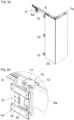
- Fig. 2a shows a partial area of the furniture 1, wherein the second furniture part 3b is hidden for reasons of improved overview.
- the guide rail 6 can be arranged on an upper side of the furniture 1, wherein the guide carriage 8 connectable to the furniture part 3b can be moved along the guide rail 6.
- Fig. 2b shows the Fig. 2a circled area in an enlarged view, showing the construction of the guide carriage 8 in more detail.
- the guide carriage 8 comprises a chassis 12 which is connected or can be connected to a preferably U-shaped support 13.
- the chassis 12 comprises at least one (not visible here) rotatable roller 18 which can roll on the guide rail 6.
- the U-shaped support 13 can be pushed in a lateral direction onto a vertically running web 6a of the guide rail 6, the web 6a being accommodated within the U-shaped section of the support 13 in the assembled position.
- a bearing part 17 is connected, preferably detachably, to the support 13, the bearing part 17 being articulated via a joint mechanism 16 to at least one fitting part 15 to be fastened to the furniture part 3b.
- the bearing part 17, the joint mechanism 16 and the fitting part 15 together form the structural unit of the connecting part 14, which can be connected to the support 13 of the chassis 12.
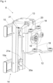
- Fig.3 shows the guide carriage 8, which has the chassis 12, the carrier 13 and the connecting part 14 to be fastened to it.
- the chassis 12 comprises at least one, preferably several, roller(s) 18, whereby two or more rollers 18 with a vertical axis of rotation and/or two or more rollers 18 with a horizontal axis of rotation can be provided.
- the connecting part 14 can be pre-assembled on the furniture part 3b, whereby the pre-assembled connecting part 14 can be connected to the carrier 13 by at least one fastening device 19.
- the fastening device 19 can have at least one bearing point 20 arranged on the carrier 13, which in an assembled position of the connecting part 14 engages in a corresponding recess 21 of the connecting part 14.
- the at least one bearing point 20 is located essentially at the same height as the chassis 12, whereby a slight lateral tilting moment is introduced into the chassis 12.
- two fastening devices 19, 19a are provided which are vertically spaced apart from one another and by means of which the connecting part 14 can be detachably connected to the carrier 13.
- the carrier 13 has at least two bearing points 20, 20a which are spaced apart from one another in the vertical direction and which, in the assembled position, each engage in two recesses 21, 21a of the connecting part 14 which are spaced apart from one another in the vertical direction.
- the connecting part 14 comprises a bearing part 17 (which is to be fastened to the bearing points 20, 20a of the carrier 13 via the recesses 21, 21a), two fitting parts 15, 15a which are spaced apart from one another in the vertical direction and are to be fastened to the furniture part 3b, and a joint mechanism 16 by means of which the fitting parts 15, 15a are pivotably connected to one another relative to the bearing part 17 about an axis which preferably runs vertically in the assembly position.
- Fig.4 shows the guide carriage 8, wherein the connecting part 14 is connected to the two bearing points 20, 20a of the carrier 13 via the recesses 21, 21a.
- Fig.5 shows the guide carriage 8 in a perspective view, wherein the connecting part 17 with the fitting parts 15, 15a to be fastened to the furniture part 3b is mounted on the support 13.
- the fitting parts 15, 15a of the connecting part 14 can be positioned relative to the chassis 12 in at least one linear direction, in the present case in the height direction (H).
- the positioning device 23 comprises a threaded section 24 which is in threaded engagement with a bearing block 25.
- the threaded section 24 is arranged on the bearing part 17 so as to be rotatable but axially immovable.
- the threaded section 24 By actuating an actuating element 27 (for example with a tool holder), the threaded section 24 can be rotated, wherein the bearing block 25 (and thus the fitting parts 15, 15a) can be adjusted in the height direction (H).
- a guide rod 26 is provided which runs parallel to the threaded section 24 and along which the bearing block 25 is mounted so as to be freely displaceable during a rotational movement of the threaded section 25.
- the furniture part 3b can be adjusted in a height direction (H) relative to the other furniture part 3a in the assembled state.
- Fig. 6a shows the guide carriage 8 in a perspective view from behind, with further positioning devices 23a being provided, by means of which the furniture part 3b to be connected to the fitting parts 15, 15a can be positioned in a lateral direction (X) relative to the other furniture part 3a.
- the fitting parts 15, 15a each have a sliding part 28 to be fastened to the furniture part 3b, which are each mounted so as to be linearly displaceable in a lateral direction (X) relative to base parts 29.
- the sliding parts 28 and the base parts 29 are each frictionally connected to one another, with the sliding parts 28 being displaceable relative to the base parts 29 by exerting force against the frictional force.
- the joint mechanism 16 for pivotably mounting the two fitting parts 15, 15a can also be seen, with the joint mechanism 16 having at least two pivotably mounted joint levers 16a, 16b.
- Fig. 6b shows the guide carriage 8, wherein the sliding parts 28 are moved by exerting force on the furniture part 3b in a lateral direction (X) relative to the base parts 29 were shifted, which is evident from a direct comparison of the Fig. 6a with the Fig. 6b is clearly evident.
- Fig.7 shows the guide carriage 8 in an exploded view.
- the drive 12 with at least one roller 18 is arranged or formed on the carrier 13, wherein the bearing part 17 of the connecting part 14 is to be fastened to the bearing points 20, 20a of the carrier 13 via the fastening devices 19, 19a with the recesses 21, 21a.
- the bearing block 25 is movably mounted on the bearing part 17, wherein the bearing block 25 is displaceably mounted relative to the bearing part 17 by rotating the actuating element 27 in the vertical direction (H) and the bearing block 25 is guided along the guide rod 26.
- the two articulated levers 16a, 16b of the articulated mechanism 16 are pivotally connected to the bearing block 25, wherein the articulated lever 16b is to be connected to a holder 31.
- the two base parts 29 of the fitting parts 15, 15a are attached to the holder 31 via support disks 32 and screws 33.
- the sliding parts 28 of the fitting parts 15, 15a are each frictionally connected to the base parts 29.
- the frictional connection between the base parts 29 and the sliding parts 28 is brought about by spring elements 30.
- the spring elements 30 are each designed as pre-tensioned leaf springs, which produce the frictional force between the base parts 29 and the sliding parts 28.
- the spring elements 30 are effective between an upper side of the base parts 29 and a bent web 28a of the sliding parts 28.
Landscapes
- Engineering & Computer Science (AREA)
- Mechanical Engineering (AREA)
- Drawers Of Furniture (AREA)
- Support Devices For Sliding Doors (AREA)
Claims (15)
- Chariot de guidage (8) pour le logement mobile d'une partie de meuble (3b) au niveau d'un rail de guidage (6), dans lequel le chariot de guidage (8) présente un mécanisme de roulement (12) avec au moins un galet de roulement (18) logé de manière rotative et au moins une partie de liaison (14) pour la liaison du chariot de guidage (8) avec la partie de meuble (3b), dans lequel au moins un dispositif de positionnement (23, 23a) est prévu, par lequel la partie de liaison (14) peut être positionnée par rapport au mécanisme de roulement (12) dans au moins un sens linéaire (H, X, Z), dans lequel le mécanisme de roulement (12) est relié à un support (13) réalisé de préférence en forme de U du chariot de guidage (8), dans lequel la partie de liaison (14) est reliée par au moins un dispositif de fixation (19) au support (13), dans lequel le dispositif de fixation (19) présente au moins un point d'appui (20) agencé au niveau du support (13) qui s'engage dans une position de montage de la partie de liaison (14) dans un évidement (21) de la partie de liaison (14), caractérisé en ce que le support (13) présente au moins deux points d'appui (20, 20a) espacés l'un de l'autre dans le sens vertical (H) qui s'engagent en position de montage respectivement dans deux évidements (21, 21a) espacés l'un de l'autre dans le sens vertical (H) de la partie de liaison (14).
- Chariot de guidage selon la revendication 1, caractérisé en ce que la partie de liaison (14) est reliée de manière amovible au mécanisme de roulement (12) par le biais du dispositif de fixation (19), de préférence par accrochage de la partie de liaison (14) au mécanisme de roulement (12), dans lequel l'au moins un dispositif de positionnement (23, 23a) est réalisé séparément du dispositif de fixation (19) et est agencé au niveau de la partie de liaison (14).
- Chariot de guidage selon la revendication 1 ou 2, caractérisé en ce qu'un premier dispositif de positionnement (23) et au moins un deuxième dispositif de positionnement (23a) sont prévus, dans lequel la partie de liaison (14) est réglable par le premier dispositif de positionnement (23) dans un sens vertical (H) par rapport au mécanisme de roulement (12) et par le deuxième dispositif de positionnement (23a) dans un sens latéral (X) par rapport au mécanisme de roulement (12), dans lequel le premier dispositif de positionnement (23) et l'au moins un deuxième dispositif de positionnement (23a) sont agencés au niveau de la partie de liaison (14).
- Chariot de guidage selon l'une quelconque des revendications 1 à 3, caractérisé en ce que l'au moins un dispositif de positionnement (23, 23a) est réalisé comme dispositif de compensation, par lequel une position de la partie de liaison (14) est comparable passivement par rapport au mécanisme de roulement (12), dans lequel une liaison autobloquante entre la partie de liaison (14) et le mécanisme de roulement (12) est prévue, dans lequel la partie de liaison (14) est ajustable par exercice de force dans le sens inverse à la liaison autobloquante par rapport au mécanisme de roulement (12).
- Chariot de guidage selon l'une quelconque des revendications 1 à 4, caractérisé en ce que l'au moins un point d'appui (20) est agencé en position de montage sensiblement à la même hauteur que le mécanisme de roulement (12).
- Chariot de guidage selon l'une quelconque des revendications 1 à 5, caractérisé en ce que la partie de liaison (14) est reliée par accrochage des évidements (21, 21a) dans les points d'appui (20, 20a) au support (13).
- Chariot de guidage selon l'une quelconque des revendications 1 à 6, caractérisé en ce que l'au moins un dispositif de positionnement (23) présente au moins un élément d'actionnement (27) logé de manière mobile, dans lequel la partie de liaison (14) est réglable par actionnement de l'élément d'actionnement (27) dans un sens vertical (H) et/ou dans un sens latéral (X) par rapport au mécanisme de roulement (12), de préférence dans lequel l'élément d'actionnement (27) est logé de manière rotative, dans lequel une section de filetage (24) est rotative par rotation de l'élément d'actionnement (27).
- Chariot de guidage selon l'une quelconque des revendications 1 à 7, caractérisé en ce que la partie de liaison (14) présente une partie d'appui (17) à fixer au support (13) et au moins une partie de ferrure (15) à fixer à la partie de meuble (3b), dans lequel la partie d'appui (17) et l'au moins une partie de ferrure (15) sont reliées de manière pivotante entre elles par le biais d'un mécanisme d'articulation (16) autour d'au moins un axe (22) s'étendant de préférence verticalement en position de montage.
- Chariot de guidage selon la revendication 8, caractérisé en ce que le mécanisme d'articulation (16) présente au moins deux leviers d'articulation (16a, 16b) logés de manière pivotante.
- Chariot de guidage selon la revendication 8 ou 9, caractérisé en ce que l'au moins une partie de ferrure (15) présente une partie de base (29) et une partie coulissante (28) à fixer à la partie de meuble (3b), dans lequel la partie coulissante (28) est logée de manière coulissante par rapport à la partie de base (29) de sorte que la partie coulissante (28) puisse être positionnée dans un sens vertical (H) et/ou dans un sens latéral (X) par rapport à la partie de base (29).
- Chariot de guidage selon la revendication 10, caractérisé en ce que la partie coulissante (28) et la partie de base (29) sont reliées l'une à l'autre par friction, dans lequel la partie coulissante (28) est mobile par rapport à la partie de base (29) par exercice de force dans le sens inverse à la force de friction.
- Chariot de guidage selon la revendication 11, caractérisé en ce que la partie coulissante (28) et la partie de base (29) sont reliées l'une à l'autre par friction par le biais d'au moins un élément de ressort (30).
- Chariot de guidage selon l'une quelconque des revendications 10 à 12, caractérisé en ce que la partie de ferrure (15) présente au moins deux parties coulissantes (28) espacées l'une de l'autre dans le sens vertical (H) qui sont logées respectivement par rapport à deux parties de base (29) espacées l'une de l'autre dans le sens vertical (H).
- Ensemble avec au moins un rail de guidage (6) et avec au moins un chariot de guidage (8) selon l'une quelconque des revendications 1 à 13, dans lequel le chariot de guidage (8) est logé de manière mobile par rapport au rail de guidage (6).
- Procédé de montage d'un chariot de guidage selon l'une quelconque des revendications 1 à 13 au niveau d'un rail de guidage, caractérisé en ce que- dans une première étape de montage, le mécanisme de roulement est monté, indépendamment et séparément de la partie de liaison, au niveau du rail de guidage,- dans une deuxième étape de montage, la partie de liaison est montée, indépendamment et séparément du mécanisme de roulement, au niveau de la partie de meuble,- dans une troisième étape de montage, la partie de meuble est reliée par le biais de la partie de liaison fixée à celle-ci au moyen d'un dispositif de fixation au mécanisme de roulement monté au niveau du rail de guidage,- dans une autre étape, dans un état relié entre la partie de liaison et le mécanisme de roulement, une position de la partie de liaison est réglée par rapport au mécanisme de roulement par l'au moins un dispositif de positionnement.
Applications Claiming Priority (2)
| Application Number | Priority Date | Filing Date | Title |
|---|---|---|---|
| ATA50392/2017A AT519904B1 (de) | 2017-05-11 | 2017-05-11 | Führungsschlitten zur verfahrbaren Lagerung eines Möbelteiles |
| PCT/AT2018/000043 WO2018204955A1 (fr) | 2017-05-11 | 2018-05-04 | Chariot de guidage pour le montage mobile d'un élément de meuble |
Publications (2)
| Publication Number | Publication Date |
|---|---|
| EP3622146A1 EP3622146A1 (fr) | 2020-03-18 |
| EP3622146B1 true EP3622146B1 (fr) | 2024-08-07 |
Family
ID=62684544
Family Applications (1)
| Application Number | Title | Priority Date | Filing Date |
|---|---|---|---|
| EP18732627.7A Active EP3622146B1 (fr) | 2017-05-11 | 2018-05-04 | Chariot de guidage pour le montage mobile d'un élément de meuble |
Country Status (8)
| Country | Link |
|---|---|
| US (1) | US11118386B2 (fr) |
| EP (1) | EP3622146B1 (fr) |
| JP (1) | JP6861846B2 (fr) |
| CN (1) | CN110582615B (fr) |
| AT (1) | AT519904B1 (fr) |
| ES (1) | ES2986305T3 (fr) |
| TW (1) | TWI661115B (fr) |
| WO (1) | WO2018204955A1 (fr) |
Families Citing this family (11)
| Publication number | Priority date | Publication date | Assignee | Title |
|---|---|---|---|---|
| AT517343B1 (de) * | 2015-06-29 | 2017-01-15 | Blum Gmbh Julius | Ausstoßvorrichtung für eine Falttür oder Falt-Schiebe-Tür |
| AT519120B1 (de) * | 2017-01-13 | 2018-04-15 | Blum Gmbh Julius | Schienenanordnung für Möbelteile |
| AT519374B1 (de) * | 2017-01-13 | 2018-06-15 | Blum Gmbh Julius | Führungssystem zur Führung eines bewegbar gelagerten Möbelteiles |
| AT522464B1 (de) * | 2019-05-17 | 2020-11-15 | Blum Gmbh Julius | Steuerkurvenanordnung zur Steuerung einer Bewegung eines Möbelteiles |
| AT17257U1 (de) * | 2019-12-19 | 2021-10-15 | Blum Gmbh Julius | Verfahren zur Montage einer Führungsanordnung für ein bewegbares Möbelteil |
| AT523303B1 (de) * | 2019-12-19 | 2023-04-15 | Blum Gmbh Julius | Führungsvorrichtung zur Führung eines Möbelteils |
| AT523374B1 (de) * | 2019-12-19 | 2021-10-15 | Blum Gmbh Julius | Verbindungsvorrichtung, insbesondere Scharnier |
| AT524380A1 (de) * | 2020-10-22 | 2022-05-15 | Blum Gmbh Julius | Verfahren zum Bewegen wenigstens eines Türflügels |
| US12473756B2 (en) * | 2021-10-27 | 2025-11-18 | The Boeing Company | Adjustable latch systems and methods |
| EP4459091A1 (fr) | 2023-05-05 | 2024-11-06 | Hawa Sliding Solutions AG | Dispositif de guidage, unité de guidage et unité fonctionnelle |
| AT526952B1 (de) * | 2023-09-07 | 2024-09-15 | Blum Gmbh Julius | Führungsanordnung zur Führung eines bewegbaren Möbelteils |
Family Cites Families (20)
| Publication number | Priority date | Publication date | Assignee | Title |
|---|---|---|---|---|
| US1365594A (en) * | 1920-05-04 | 1921-01-11 | Kules Leo | Door-hanger |
| US1384325A (en) * | 1920-08-23 | 1921-07-12 | Kules Leo | Door-hanger |
| US2710422A (en) * | 1953-10-15 | 1955-06-14 | Stanley Works | Sliding door hanger |
| US4478006A (en) * | 1983-08-11 | 1984-10-23 | L. E. Johnson, Inc. | Sliding door frame corner lock |
| JPH01139783A (ja) | 1987-11-25 | 1989-06-01 | Mitsubishi Heavy Ind Ltd | 高導電性高分子の調製法 |
| US5085262A (en) | 1989-02-08 | 1992-02-04 | Daiyusu Kinzoku Co., Ltd. | Device for supporting folding doors |
| DE3903700C2 (de) * | 1989-02-08 | 1999-04-08 | Yoshiji Tutikawa | Lagerung für Falttüren |
| JP2534616Y2 (ja) * | 1989-11-30 | 1997-05-07 | 善司 土川 | 折り戸の支持装置 |
| US6845849B2 (en) * | 2003-01-21 | 2005-01-25 | Thyssen Elevator Capital Corp | Height adjustment clip for an elevator door |
| US6698138B1 (en) * | 2003-04-09 | 2004-03-02 | Heade Technology Co., Ltd. | Adjustable pulley assembly for a suspended door |
| FR2941857B1 (fr) * | 2009-02-09 | 2013-12-20 | Somfy Sas | Chariot d'entrainement pour rideau coulissant |
| EP2218858B1 (fr) * | 2009-02-15 | 2013-10-16 | Hawa Ag | Train de roulement pour un élément de séparation, élément de séparation et dispositif |
| ES2397458T3 (es) * | 2009-04-28 | 2013-03-07 | Hawa Ag | Dispositivo de desplazamiento para sostener de forma pivotante elementos de separación, y artículo de mobiliario |
| SE535000C2 (sv) * | 2010-07-07 | 2012-03-13 | Assa Abloy Ip Ab | Löpvagn för en skjutdörr och metod för byte av hjul på en löpvagn samt användning |
| DE102010038140B4 (de) * | 2010-10-13 | 2020-06-18 | Hettich-Heinze Gmbh & Co. Kg | Beschlag für eine Schiebetür |
| DE202011050006U1 (de) * | 2011-04-29 | 2012-08-02 | Hücking GmbH | Schiebetürbeschlag,insbesondere für Möbel |
| US9085924B2 (en) * | 2012-12-04 | 2015-07-21 | Milgard Manufacturing Incorporated | Lift adjust sliding door roller |
| EP3913177B1 (fr) | 2012-12-05 | 2025-05-07 | Hawa Sliding Solutions AG | Dispositif de liaison pour éléments de séparation et unité de fonctionnement |
| EP3088645B1 (fr) * | 2015-04-27 | 2018-06-27 | Hawa Sliding Solutions AG | Dispositif de liaison pour une porte coulissante |
| AT519479B1 (de) * | 2017-05-11 | 2018-07-15 | Blum Gmbh Julius | Führungssystem zur Führung eines Türflügels |
-
2017
- 2017-05-11 AT ATA50392/2017A patent/AT519904B1/de active
-
2018
- 2018-04-24 TW TW107113810A patent/TWI661115B/zh active
- 2018-05-04 ES ES18732627T patent/ES2986305T3/es active Active
- 2018-05-04 WO PCT/AT2018/000043 patent/WO2018204955A1/fr not_active Ceased
- 2018-05-04 CN CN201880029852.XA patent/CN110582615B/zh active Active
- 2018-05-04 EP EP18732627.7A patent/EP3622146B1/fr active Active
- 2018-05-04 JP JP2019559810A patent/JP6861846B2/ja active Active
-
2019
- 2019-09-25 US US16/582,617 patent/US11118386B2/en active Active
Also Published As
| Publication number | Publication date |
|---|---|
| CN110582615B (zh) | 2022-07-26 |
| EP3622146A1 (fr) | 2020-03-18 |
| TW201901017A (zh) | 2019-01-01 |
| US11118386B2 (en) | 2021-09-14 |
| WO2018204955A1 (fr) | 2018-11-15 |
| AT519904B1 (de) | 2022-07-15 |
| AT519904A1 (de) | 2018-11-15 |
| TWI661115B (zh) | 2019-06-01 |
| ES2986305T3 (es) | 2024-11-11 |
| JP6861846B2 (ja) | 2021-04-21 |
| JP2020518743A (ja) | 2020-06-25 |
| CN110582615A (zh) | 2019-12-17 |
| US20200018106A1 (en) | 2020-01-16 |
Similar Documents
| Publication | Publication Date | Title |
|---|---|---|
| AT519904B1 (de) | Führungsschlitten zur verfahrbaren Lagerung eines Möbelteiles | |
| EP3622154B1 (fr) | Système de guidage pour le guidage d'un battant de porte | |
| EP3880922B1 (fr) | Système de guidage pour le guidage d'un battant de porte monté de manière mobile | |
| EP4325013B1 (fr) | Système de guidage pour guider au moins un battant de porte monté mobile | |
| EP3969703B1 (fr) | Système de guidage pour guider au moins un battant de porte | |
| EP3880921B1 (fr) | Chariot de guidage servant au montage mobile d'un élément de meuble | |
| EP4077850B1 (fr) | Système de guidage permettant de guider un battant de porte monté de manière mobile | |
| EP3105397A1 (fr) | Ferrure de porte pouclisante | |
| EP4263991B1 (fr) | Système de guidage pour guider au moins un battant de porte par rapport à un corps de meuble | |
| EP2799651B1 (fr) | Ferrure de porte coulissante pour meuble | |
| EP3880918B1 (fr) | Charnière de meuble | |
| EP3058156A1 (fr) | Dispositif de guidage d'une porte coulissante, et procédé de montage d'une porte coulissante | |
| EP0451737A2 (fr) | Ferrure d'articulation pour meuble d'angle | |
| WO2022126167A1 (fr) | Ensemble de guidage d'une partie de meuble mobile | |
| DE102012210590B4 (de) | Antrieb zum Öffnen und/oder Schließen eines beweglichen Flügels einer Tür oder eines Fensters | |
| EP4390022A2 (fr) | Agencement doté d'une charnière de meuble et d'un couvercle | |
| DE10126962A1 (de) | Fahreinrichtung für verfahrbare Gegenstände bzw. verfahrbarer Gegenstand | |
| AT521333B1 (de) | Schubladenausziehführung | |
| DE202008016050U1 (de) | Doppelantrieb für Möbel | |
| EP4174268B1 (fr) | Ferrure roulante de porte coulissante et agencement de porte coulissante associé | |
| AT525275B1 (de) | Führungssystem zur Führung wenigstens eines bewegbaren Möbelteiles | |
| EP3636865B1 (fr) | Charnière pourvue de dispositif d'encliquetage pour la position zéro | |
| EP3045630B1 (fr) | Dispositif de guidage pour un vantail d'une porte coulissante | |
| EP4594588A1 (fr) | Système de guidage pour guider au moins un battant de porte monté mobile | |
| DE8709707U1 (de) | Auszugführung mit Korpusschiene und Auszugträger |
Legal Events
| Date | Code | Title | Description |
|---|---|---|---|
| STAA | Information on the status of an ep patent application or granted ep patent |
Free format text: STATUS: UNKNOWN |
|
| STAA | Information on the status of an ep patent application or granted ep patent |
Free format text: STATUS: THE INTERNATIONAL PUBLICATION HAS BEEN MADE |
|
| PUAI | Public reference made under article 153(3) epc to a published international application that has entered the european phase |
Free format text: ORIGINAL CODE: 0009012 |
|
| STAA | Information on the status of an ep patent application or granted ep patent |
Free format text: STATUS: REQUEST FOR EXAMINATION WAS MADE |
|
| 17P | Request for examination filed |
Effective date: 20190916 |
|
| AK | Designated contracting states |
Kind code of ref document: A1 Designated state(s): AL AT BE BG CH CY CZ DE DK EE ES FI FR GB GR HR HU IE IS IT LI LT LU LV MC MK MT NL NO PL PT RO RS SE SI SK SM TR |
|
| AX | Request for extension of the european patent |
Extension state: BA ME |
|
| DAV | Request for validation of the european patent (deleted) | ||
| DAX | Request for extension of the european patent (deleted) | ||
| STAA | Information on the status of an ep patent application or granted ep patent |
Free format text: STATUS: EXAMINATION IS IN PROGRESS |
|
| 17Q | First examination report despatched |
Effective date: 20210111 |
|
| P01 | Opt-out of the competence of the unified patent court (upc) registered |
Effective date: 20230523 |
|
| GRAP | Despatch of communication of intention to grant a patent |
Free format text: ORIGINAL CODE: EPIDOSNIGR1 |
|
| STAA | Information on the status of an ep patent application or granted ep patent |
Free format text: STATUS: GRANT OF PATENT IS INTENDED |
|
| GRAS | Grant fee paid |
Free format text: ORIGINAL CODE: EPIDOSNIGR3 |
|
| INTG | Intention to grant announced |
Effective date: 20240529 |
|
| GRAA | (expected) grant |
Free format text: ORIGINAL CODE: 0009210 |
|
| STAA | Information on the status of an ep patent application or granted ep patent |
Free format text: STATUS: THE PATENT HAS BEEN GRANTED |
|
| AK | Designated contracting states |
Kind code of ref document: B1 Designated state(s): AL AT BE BG CH CY CZ DE DK EE ES FI FR GB GR HR HU IE IS IT LI LT LU LV MC MK MT NL NO PL PT RO RS SE SI SK SM TR |
|
| REG | Reference to a national code |
Ref country code: GB Ref legal event code: FG4D Free format text: NOT ENGLISH |
|
| REG | Reference to a national code |
Ref country code: CH Ref legal event code: EP |
|
| REG | Reference to a national code |
Ref country code: DE Ref legal event code: R096 Ref document number: 502018014982 Country of ref document: DE |
|
| REG | Reference to a national code |
Ref country code: IE Ref legal event code: FG4D Free format text: LANGUAGE OF EP DOCUMENT: GERMAN |
|
| REG | Reference to a national code |
Ref country code: ES Ref legal event code: FG2A Ref document number: 2986305 Country of ref document: ES Kind code of ref document: T3 Effective date: 20241111 |
|
| REG | Reference to a national code |
Ref country code: LT Ref legal event code: MG9D |
|
| REG | Reference to a national code |
Ref country code: NL Ref legal event code: MP Effective date: 20240807 |
|
| PG25 | Lapsed in a contracting state [announced via postgrant information from national office to epo] |
Ref country code: NO Free format text: LAPSE BECAUSE OF FAILURE TO SUBMIT A TRANSLATION OF THE DESCRIPTION OR TO PAY THE FEE WITHIN THE PRESCRIBED TIME-LIMIT Effective date: 20241107 |
|
| PG25 | Lapsed in a contracting state [announced via postgrant information from national office to epo] |
Ref country code: FI Free format text: LAPSE BECAUSE OF FAILURE TO SUBMIT A TRANSLATION OF THE DESCRIPTION OR TO PAY THE FEE WITHIN THE PRESCRIBED TIME-LIMIT Effective date: 20240807 Ref country code: NL Free format text: LAPSE BECAUSE OF FAILURE TO SUBMIT A TRANSLATION OF THE DESCRIPTION OR TO PAY THE FEE WITHIN THE PRESCRIBED TIME-LIMIT Effective date: 20240807 Ref country code: PL Free format text: LAPSE BECAUSE OF FAILURE TO SUBMIT A TRANSLATION OF THE DESCRIPTION OR TO PAY THE FEE WITHIN THE PRESCRIBED TIME-LIMIT Effective date: 20240807 Ref country code: GR Free format text: LAPSE BECAUSE OF FAILURE TO SUBMIT A TRANSLATION OF THE DESCRIPTION OR TO PAY THE FEE WITHIN THE PRESCRIBED TIME-LIMIT Effective date: 20241108 Ref country code: PT Free format text: LAPSE BECAUSE OF FAILURE TO SUBMIT A TRANSLATION OF THE DESCRIPTION OR TO PAY THE FEE WITHIN THE PRESCRIBED TIME-LIMIT Effective date: 20241209 |
|
| PG25 | Lapsed in a contracting state [announced via postgrant information from national office to epo] |
Ref country code: BG Free format text: LAPSE BECAUSE OF FAILURE TO SUBMIT A TRANSLATION OF THE DESCRIPTION OR TO PAY THE FEE WITHIN THE PRESCRIBED TIME-LIMIT Effective date: 20240807 |
|
| PG25 | Lapsed in a contracting state [announced via postgrant information from national office to epo] |
Ref country code: LV Free format text: LAPSE BECAUSE OF FAILURE TO SUBMIT A TRANSLATION OF THE DESCRIPTION OR TO PAY THE FEE WITHIN THE PRESCRIBED TIME-LIMIT Effective date: 20240807 |
|
| PG25 | Lapsed in a contracting state [announced via postgrant information from national office to epo] |
Ref country code: IS Free format text: LAPSE BECAUSE OF FAILURE TO SUBMIT A TRANSLATION OF THE DESCRIPTION OR TO PAY THE FEE WITHIN THE PRESCRIBED TIME-LIMIT Effective date: 20241207 |
|
| PG25 | Lapsed in a contracting state [announced via postgrant information from national office to epo] |
Ref country code: HR Free format text: LAPSE BECAUSE OF FAILURE TO SUBMIT A TRANSLATION OF THE DESCRIPTION OR TO PAY THE FEE WITHIN THE PRESCRIBED TIME-LIMIT Effective date: 20240807 |
|
| PG25 | Lapsed in a contracting state [announced via postgrant information from national office to epo] |
Ref country code: RS Free format text: LAPSE BECAUSE OF FAILURE TO SUBMIT A TRANSLATION OF THE DESCRIPTION OR TO PAY THE FEE WITHIN THE PRESCRIBED TIME-LIMIT Effective date: 20241107 |
|
| PG25 | Lapsed in a contracting state [announced via postgrant information from national office to epo] |
Ref country code: RS Free format text: LAPSE BECAUSE OF FAILURE TO SUBMIT A TRANSLATION OF THE DESCRIPTION OR TO PAY THE FEE WITHIN THE PRESCRIBED TIME-LIMIT Effective date: 20241107 Ref country code: PT Free format text: LAPSE BECAUSE OF FAILURE TO SUBMIT A TRANSLATION OF THE DESCRIPTION OR TO PAY THE FEE WITHIN THE PRESCRIBED TIME-LIMIT Effective date: 20241209 Ref country code: PL Free format text: LAPSE BECAUSE OF FAILURE TO SUBMIT A TRANSLATION OF THE DESCRIPTION OR TO PAY THE FEE WITHIN THE PRESCRIBED TIME-LIMIT Effective date: 20240807 Ref country code: NO Free format text: LAPSE BECAUSE OF FAILURE TO SUBMIT A TRANSLATION OF THE DESCRIPTION OR TO PAY THE FEE WITHIN THE PRESCRIBED TIME-LIMIT Effective date: 20241107 Ref country code: NL Free format text: LAPSE BECAUSE OF FAILURE TO SUBMIT A TRANSLATION OF THE DESCRIPTION OR TO PAY THE FEE WITHIN THE PRESCRIBED TIME-LIMIT Effective date: 20240807 Ref country code: LV Free format text: LAPSE BECAUSE OF FAILURE TO SUBMIT A TRANSLATION OF THE DESCRIPTION OR TO PAY THE FEE WITHIN THE PRESCRIBED TIME-LIMIT Effective date: 20240807 Ref country code: IS Free format text: LAPSE BECAUSE OF FAILURE TO SUBMIT A TRANSLATION OF THE DESCRIPTION OR TO PAY THE FEE WITHIN THE PRESCRIBED TIME-LIMIT Effective date: 20241207 Ref country code: HR Free format text: LAPSE BECAUSE OF FAILURE TO SUBMIT A TRANSLATION OF THE DESCRIPTION OR TO PAY THE FEE WITHIN THE PRESCRIBED TIME-LIMIT Effective date: 20240807 Ref country code: GR Free format text: LAPSE BECAUSE OF FAILURE TO SUBMIT A TRANSLATION OF THE DESCRIPTION OR TO PAY THE FEE WITHIN THE PRESCRIBED TIME-LIMIT Effective date: 20241108 Ref country code: FI Free format text: LAPSE BECAUSE OF FAILURE TO SUBMIT A TRANSLATION OF THE DESCRIPTION OR TO PAY THE FEE WITHIN THE PRESCRIBED TIME-LIMIT Effective date: 20240807 Ref country code: BG Free format text: LAPSE BECAUSE OF FAILURE TO SUBMIT A TRANSLATION OF THE DESCRIPTION OR TO PAY THE FEE WITHIN THE PRESCRIBED TIME-LIMIT Effective date: 20240807 |
|
| PG25 | Lapsed in a contracting state [announced via postgrant information from national office to epo] |
Ref country code: SM Free format text: LAPSE BECAUSE OF FAILURE TO SUBMIT A TRANSLATION OF THE DESCRIPTION OR TO PAY THE FEE WITHIN THE PRESCRIBED TIME-LIMIT Effective date: 20240807 Ref country code: DK Free format text: LAPSE BECAUSE OF FAILURE TO SUBMIT A TRANSLATION OF THE DESCRIPTION OR TO PAY THE FEE WITHIN THE PRESCRIBED TIME-LIMIT Effective date: 20240807 Ref country code: RO Free format text: LAPSE BECAUSE OF FAILURE TO SUBMIT A TRANSLATION OF THE DESCRIPTION OR TO PAY THE FEE WITHIN THE PRESCRIBED TIME-LIMIT Effective date: 20240807 |
|
| PG25 | Lapsed in a contracting state [announced via postgrant information from national office to epo] |
Ref country code: EE Free format text: LAPSE BECAUSE OF FAILURE TO SUBMIT A TRANSLATION OF THE DESCRIPTION OR TO PAY THE FEE WITHIN THE PRESCRIBED TIME-LIMIT Effective date: 20240807 |
|
| PG25 | Lapsed in a contracting state [announced via postgrant information from national office to epo] |
Ref country code: CZ Free format text: LAPSE BECAUSE OF FAILURE TO SUBMIT A TRANSLATION OF THE DESCRIPTION OR TO PAY THE FEE WITHIN THE PRESCRIBED TIME-LIMIT Effective date: 20240807 |
|
| PG25 | Lapsed in a contracting state [announced via postgrant information from national office to epo] |
Ref country code: SK Free format text: LAPSE BECAUSE OF FAILURE TO SUBMIT A TRANSLATION OF THE DESCRIPTION OR TO PAY THE FEE WITHIN THE PRESCRIBED TIME-LIMIT Effective date: 20240807 |
|
| REG | Reference to a national code |
Ref country code: DE Ref legal event code: R097 Ref document number: 502018014982 Country of ref document: DE |
|
| PLBE | No opposition filed within time limit |
Free format text: ORIGINAL CODE: 0009261 |
|
| STAA | Information on the status of an ep patent application or granted ep patent |
Free format text: STATUS: NO OPPOSITION FILED WITHIN TIME LIMIT |
|
| PGFP | Annual fee paid to national office [announced via postgrant information from national office to epo] |
Ref country code: DE Payment date: 20250528 Year of fee payment: 8 |
|
| PGFP | Annual fee paid to national office [announced via postgrant information from national office to epo] |
Ref country code: ES Payment date: 20250612 Year of fee payment: 8 |
|
| 26N | No opposition filed |
Effective date: 20250508 |
|
| PGFP | Annual fee paid to national office [announced via postgrant information from national office to epo] |
Ref country code: CH Payment date: 20250601 Year of fee payment: 8 |
|
| PGFP | Annual fee paid to national office [announced via postgrant information from national office to epo] |
Ref country code: AT Payment date: 20250528 Year of fee payment: 8 |
|
| PGFP | Annual fee paid to national office [announced via postgrant information from national office to epo] |
Ref country code: TR Payment date: 20250421 Year of fee payment: 8 |
|
| PG25 | Lapsed in a contracting state [announced via postgrant information from national office to epo] |
Ref country code: SE Free format text: LAPSE BECAUSE OF FAILURE TO SUBMIT A TRANSLATION OF THE DESCRIPTION OR TO PAY THE FEE WITHIN THE PRESCRIBED TIME-LIMIT Effective date: 20240807 |
|
| PG25 | Lapsed in a contracting state [announced via postgrant information from national office to epo] |
Ref country code: LU Free format text: LAPSE BECAUSE OF NON-PAYMENT OF DUE FEES Effective date: 20250504 |
|
| GBPC | Gb: european patent ceased through non-payment of renewal fee |
Effective date: 20250504 |
|
| REG | Reference to a national code |
Ref country code: BE Ref legal event code: MM Effective date: 20250531 |
|
| PG25 | Lapsed in a contracting state [announced via postgrant information from national office to epo] |
Ref country code: MC Free format text: LAPSE BECAUSE OF FAILURE TO SUBMIT A TRANSLATION OF THE DESCRIPTION OR TO PAY THE FEE WITHIN THE PRESCRIBED TIME-LIMIT Effective date: 20240807 |
|
| PG25 | Lapsed in a contracting state [announced via postgrant information from national office to epo] |
Ref country code: GB Free format text: LAPSE BECAUSE OF NON-PAYMENT OF DUE FEES Effective date: 20250504 |
|
| PG25 | Lapsed in a contracting state [announced via postgrant information from national office to epo] |
Ref country code: IE Free format text: LAPSE BECAUSE OF NON-PAYMENT OF DUE FEES Effective date: 20250504 |
|
| PG25 | Lapsed in a contracting state [announced via postgrant information from national office to epo] |
Ref country code: IT Free format text: LAPSE BECAUSE OF NON-PAYMENT OF DUE FEES Effective date: 20250504 Ref country code: BE Free format text: LAPSE BECAUSE OF NON-PAYMENT OF DUE FEES Effective date: 20250531 |
|
| PG25 | Lapsed in a contracting state [announced via postgrant information from national office to epo] |
Ref country code: FR Free format text: LAPSE BECAUSE OF NON-PAYMENT OF DUE FEES Effective date: 20250531 |