EP3735505B1 - Ensemble charnière amorti - Google Patents
Ensemble charnière amorti Download PDFInfo
- Publication number
- EP3735505B1 EP3735505B1 EP19796662.5A EP19796662A EP3735505B1 EP 3735505 B1 EP3735505 B1 EP 3735505B1 EP 19796662 A EP19796662 A EP 19796662A EP 3735505 B1 EP3735505 B1 EP 3735505B1
- Authority
- EP
- European Patent Office
- Prior art keywords
- closure
- removable
- barrel
- compression
- range
- Prior art date
- Legal status (The legal status is an assumption and is not a legal conclusion. Google has not performed a legal analysis and makes no representation as to the accuracy of the status listed.)
- Active
Links
Images



Classifications
-
- E—FIXED CONSTRUCTIONS
- E05—LOCKS; KEYS; WINDOW OR DOOR FITTINGS; SAFES
- E05F—DEVICES FOR MOVING WINGS INTO OPEN OR CLOSED POSITION; CHECKS FOR WINGS; WING FITTINGS NOT OTHERWISE PROVIDED FOR, CONCERNED WITH THE FUNCTIONING OF THE WING
- E05F3/00—Closers or openers with braking devices, e.g. checks; Construction of pneumatic or liquid braking devices
- E05F3/20—Closers or openers with braking devices, e.g. checks; Construction of pneumatic or liquid braking devices in hinges
-
- E—FIXED CONSTRUCTIONS
- E05—LOCKS; KEYS; WINDOW OR DOOR FITTINGS; SAFES
- E05F—DEVICES FOR MOVING WINGS INTO OPEN OR CLOSED POSITION; CHECKS FOR WINGS; WING FITTINGS NOT OTHERWISE PROVIDED FOR, CONCERNED WITH THE FUNCTIONING OF THE WING
- E05F1/00—Closers or openers for wings, not otherwise provided for in this subclass
- E05F1/08—Closers or openers for wings, not otherwise provided for in this subclass spring-actuated, e.g. for horizontally sliding wings
- E05F1/10—Closers or openers for wings, not otherwise provided for in this subclass spring-actuated, e.g. for horizontally sliding wings for swinging wings, e.g. counterbalance
- E05F1/12—Mechanisms in the shape of hinges or pivots, operated by springs
- E05F1/1207—Mechanisms in the shape of hinges or pivots, operated by springs with a coil spring parallel with the pivot axis
-
- E—FIXED CONSTRUCTIONS
- E05—LOCKS; KEYS; WINDOW OR DOOR FITTINGS; SAFES
- E05D—HINGES OR SUSPENSION DEVICES FOR DOORS, WINDOWS OR WINGS
- E05D11/00—Additional features or accessories of hinges
- E05D11/08—Friction devices between relatively-movable hinge parts
-
- E—FIXED CONSTRUCTIONS
- E05—LOCKS; KEYS; WINDOW OR DOOR FITTINGS; SAFES
- E05D—HINGES OR SUSPENSION DEVICES FOR DOORS, WINDOWS OR WINGS
- E05D11/00—Additional features or accessories of hinges
- E05D11/08—Friction devices between relatively-movable hinge parts
- E05D11/082—Friction devices between relatively-movable hinge parts with substantially radial friction, e.g. cylindrical friction surfaces
-
- E—FIXED CONSTRUCTIONS
- E05—LOCKS; KEYS; WINDOW OR DOOR FITTINGS; SAFES
- E05D—HINGES OR SUSPENSION DEVICES FOR DOORS, WINDOWS OR WINGS
- E05D5/00—Construction of single parts, e.g. the parts for attachment
- E05D5/02—Parts for attachment, e.g. flaps
- E05D5/04—Flat flaps
-
- E—FIXED CONSTRUCTIONS
- E05—LOCKS; KEYS; WINDOW OR DOOR FITTINGS; SAFES
- E05D—HINGES OR SUSPENSION DEVICES FOR DOORS, WINDOWS OR WINGS
- E05D7/00—Hinges or pivots of special construction
- E05D7/08—Hinges or pivots of special construction for use in suspensions comprising two spigots placed at opposite edges of the wing, especially at the top and the bottom, e.g. trunnions
- E05D7/082—Hinges or pivots of special construction for use in suspensions comprising two spigots placed at opposite edges of the wing, especially at the top and the bottom, e.g. trunnions the pivot axis of the wing being situated at a considerable distance from the edges of the wing, e.g. for balanced wings
- E05D7/086—Braking devices structurally combined with hinges
-
- E—FIXED CONSTRUCTIONS
- E05—LOCKS; KEYS; WINDOW OR DOOR FITTINGS; SAFES
- E05F—DEVICES FOR MOVING WINGS INTO OPEN OR CLOSED POSITION; CHECKS FOR WINGS; WING FITTINGS NOT OTHERWISE PROVIDED FOR, CONCERNED WITH THE FUNCTIONING OF THE WING
- E05F1/00—Closers or openers for wings, not otherwise provided for in this subclass
- E05F1/08—Closers or openers for wings, not otherwise provided for in this subclass spring-actuated, e.g. for horizontally sliding wings
- E05F1/10—Closers or openers for wings, not otherwise provided for in this subclass spring-actuated, e.g. for horizontally sliding wings for swinging wings, e.g. counterbalance
- E05F1/12—Mechanisms in the shape of hinges or pivots, operated by springs
- E05F1/1207—Mechanisms in the shape of hinges or pivots, operated by springs with a coil spring parallel with the pivot axis
- E05F1/1223—Mechanisms in the shape of hinges or pivots, operated by springs with a coil spring parallel with the pivot axis with a compression or traction spring
-
- E—FIXED CONSTRUCTIONS
- E05—LOCKS; KEYS; WINDOW OR DOOR FITTINGS; SAFES
- E05F—DEVICES FOR MOVING WINGS INTO OPEN OR CLOSED POSITION; CHECKS FOR WINGS; WING FITTINGS NOT OTHERWISE PROVIDED FOR, CONCERNED WITH THE FUNCTIONING OF THE WING
- E05F3/00—Closers or openers with braking devices, e.g. checks; Construction of pneumatic or liquid braking devices
- E05F3/02—Closers or openers with braking devices, e.g. checks; Construction of pneumatic or liquid braking devices with pneumatic piston brakes
-
- E—FIXED CONSTRUCTIONS
- E05—LOCKS; KEYS; WINDOW OR DOOR FITTINGS; SAFES
- E05D—HINGES OR SUSPENSION DEVICES FOR DOORS, WINDOWS OR WINGS
- E05D3/00—Hinges with pins
- E05D3/02—Hinges with pins with one pin
- E05D2003/025—Hinges with pins with one pin having three knuckles
-
- E—FIXED CONSTRUCTIONS
- E05—LOCKS; KEYS; WINDOW OR DOOR FITTINGS; SAFES
- E05D—HINGES OR SUSPENSION DEVICES FOR DOORS, WINDOWS OR WINGS
- E05D3/00—Hinges with pins
- E05D3/02—Hinges with pins with one pin
- E05D2003/025—Hinges with pins with one pin having three knuckles
- E05D2003/027—Hinges with pins with one pin having three knuckles the end knuckles being mutually connected
-
- E—FIXED CONSTRUCTIONS
- E05—LOCKS; KEYS; WINDOW OR DOOR FITTINGS; SAFES
- E05F—DEVICES FOR MOVING WINGS INTO OPEN OR CLOSED POSITION; CHECKS FOR WINGS; WING FITTINGS NOT OTHERWISE PROVIDED FOR, CONCERNED WITH THE FUNCTIONING OF THE WING
- E05F1/00—Closers or openers for wings, not otherwise provided for in this subclass
- E05F1/08—Closers or openers for wings, not otherwise provided for in this subclass spring-actuated, e.g. for horizontally sliding wings
- E05F1/10—Closers or openers for wings, not otherwise provided for in this subclass spring-actuated, e.g. for horizontally sliding wings for swinging wings, e.g. counterbalance
- E05F1/1008—Closers or openers for wings, not otherwise provided for in this subclass spring-actuated, e.g. for horizontally sliding wings for swinging wings, e.g. counterbalance with a coil spring parallel with the pivot axis
- E05F1/1025—Closers or openers for wings, not otherwise provided for in this subclass spring-actuated, e.g. for horizontally sliding wings for swinging wings, e.g. counterbalance with a coil spring parallel with the pivot axis with a compression or traction spring
-
- E—FIXED CONSTRUCTIONS
- E05—LOCKS; KEYS; WINDOW OR DOOR FITTINGS; SAFES
- E05Y—INDEXING SCHEME ASSOCIATED WITH SUBCLASSES E05D AND E05F, RELATING TO CONSTRUCTION ELEMENTS, ELECTRIC CONTROL, POWER SUPPLY, POWER SIGNAL OR TRANSMISSION, USER INTERFACES, MOUNTING OR COUPLING, DETAILS, ACCESSORIES, AUXILIARY OPERATIONS NOT OTHERWISE PROVIDED FOR, APPLICATION THEREOF
- E05Y2201/00—Constructional elements; Accessories therefor
- E05Y2201/40—Motors; Magnets; Springs; Weights; Accessories therefor
- E05Y2201/404—Function thereof
- E05Y2201/408—Function thereof for braking
-
- E—FIXED CONSTRUCTIONS
- E05—LOCKS; KEYS; WINDOW OR DOOR FITTINGS; SAFES
- E05Y—INDEXING SCHEME ASSOCIATED WITH SUBCLASSES E05D AND E05F, RELATING TO CONSTRUCTION ELEMENTS, ELECTRIC CONTROL, POWER SUPPLY, POWER SIGNAL OR TRANSMISSION, USER INTERFACES, MOUNTING OR COUPLING, DETAILS, ACCESSORIES, AUXILIARY OPERATIONS NOT OTHERWISE PROVIDED FOR, APPLICATION THEREOF
- E05Y2201/00—Constructional elements; Accessories therefor
- E05Y2201/40—Motors; Magnets; Springs; Weights; Accessories therefor
- E05Y2201/404—Function thereof
- E05Y2201/41—Function thereof for closing
- E05Y2201/412—Function thereof for closing for the final closing movement
-
- E—FIXED CONSTRUCTIONS
- E05—LOCKS; KEYS; WINDOW OR DOOR FITTINGS; SAFES
- E05Y—INDEXING SCHEME ASSOCIATED WITH SUBCLASSES E05D AND E05F, RELATING TO CONSTRUCTION ELEMENTS, ELECTRIC CONTROL, POWER SUPPLY, POWER SIGNAL OR TRANSMISSION, USER INTERFACES, MOUNTING OR COUPLING, DETAILS, ACCESSORIES, AUXILIARY OPERATIONS NOT OTHERWISE PROVIDED FOR, APPLICATION THEREOF
- E05Y2201/00—Constructional elements; Accessories therefor
- E05Y2201/40—Motors; Magnets; Springs; Weights; Accessories therefor
- E05Y2201/47—Springs
- E05Y2201/474—Compression springs
-
- E—FIXED CONSTRUCTIONS
- E05—LOCKS; KEYS; WINDOW OR DOOR FITTINGS; SAFES
- E05Y—INDEXING SCHEME ASSOCIATED WITH SUBCLASSES E05D AND E05F, RELATING TO CONSTRUCTION ELEMENTS, ELECTRIC CONTROL, POWER SUPPLY, POWER SIGNAL OR TRANSMISSION, USER INTERFACES, MOUNTING OR COUPLING, DETAILS, ACCESSORIES, AUXILIARY OPERATIONS NOT OTHERWISE PROVIDED FOR, APPLICATION THEREOF
- E05Y2201/00—Constructional elements; Accessories therefor
- E05Y2201/40—Motors; Magnets; Springs; Weights; Accessories therefor
- E05Y2201/47—Springs
- E05Y2201/484—Torsion springs
-
- E—FIXED CONSTRUCTIONS
- E05—LOCKS; KEYS; WINDOW OR DOOR FITTINGS; SAFES
- E05Y—INDEXING SCHEME ASSOCIATED WITH SUBCLASSES E05D AND E05F, RELATING TO CONSTRUCTION ELEMENTS, ELECTRIC CONTROL, POWER SUPPLY, POWER SIGNAL OR TRANSMISSION, USER INTERFACES, MOUNTING OR COUPLING, DETAILS, ACCESSORIES, AUXILIARY OPERATIONS NOT OTHERWISE PROVIDED FOR, APPLICATION THEREOF
- E05Y2201/00—Constructional elements; Accessories therefor
- E05Y2201/60—Suspension or transmission members; Accessories therefor
- E05Y2201/622—Suspension or transmission members elements
- E05Y2201/638—Cams; Ramps
-
- E—FIXED CONSTRUCTIONS
- E05—LOCKS; KEYS; WINDOW OR DOOR FITTINGS; SAFES
- E05Y—INDEXING SCHEME ASSOCIATED WITH SUBCLASSES E05D AND E05F, RELATING TO CONSTRUCTION ELEMENTS, ELECTRIC CONTROL, POWER SUPPLY, POWER SIGNAL OR TRANSMISSION, USER INTERFACES, MOUNTING OR COUPLING, DETAILS, ACCESSORIES, AUXILIARY OPERATIONS NOT OTHERWISE PROVIDED FOR, APPLICATION THEREOF
- E05Y2201/00—Constructional elements; Accessories therefor
- E05Y2201/60—Suspension or transmission members; Accessories therefor
- E05Y2201/622—Suspension or transmission members elements
- E05Y2201/696—Screw mechanisms
-
- E—FIXED CONSTRUCTIONS
- E05—LOCKS; KEYS; WINDOW OR DOOR FITTINGS; SAFES
- E05Y—INDEXING SCHEME ASSOCIATED WITH SUBCLASSES E05D AND E05F, RELATING TO CONSTRUCTION ELEMENTS, ELECTRIC CONTROL, POWER SUPPLY, POWER SIGNAL OR TRANSMISSION, USER INTERFACES, MOUNTING OR COUPLING, DETAILS, ACCESSORIES, AUXILIARY OPERATIONS NOT OTHERWISE PROVIDED FOR, APPLICATION THEREOF
- E05Y2201/00—Constructional elements; Accessories therefor
- E05Y2201/60—Suspension or transmission members; Accessories therefor
- E05Y2201/622—Suspension or transmission members elements
- E05Y2201/696—Screw mechanisms
- E05Y2201/702—Spindles; Worms
-
- E—FIXED CONSTRUCTIONS
- E05—LOCKS; KEYS; WINDOW OR DOOR FITTINGS; SAFES
- E05Y—INDEXING SCHEME ASSOCIATED WITH SUBCLASSES E05D AND E05F, RELATING TO CONSTRUCTION ELEMENTS, ELECTRIC CONTROL, POWER SUPPLY, POWER SIGNAL OR TRANSMISSION, USER INTERFACES, MOUNTING OR COUPLING, DETAILS, ACCESSORIES, AUXILIARY OPERATIONS NOT OTHERWISE PROVIDED FOR, APPLICATION THEREOF
- E05Y2600/00—Mounting or coupling arrangements for elements provided for in this subclass
- E05Y2600/10—Adjustable
- E05Y2600/12—Adjustable by manual operation
-
- E—FIXED CONSTRUCTIONS
- E05—LOCKS; KEYS; WINDOW OR DOOR FITTINGS; SAFES
- E05Y—INDEXING SCHEME ASSOCIATED WITH SUBCLASSES E05D AND E05F, RELATING TO CONSTRUCTION ELEMENTS, ELECTRIC CONTROL, POWER SUPPLY, POWER SIGNAL OR TRANSMISSION, USER INTERFACES, MOUNTING OR COUPLING, DETAILS, ACCESSORIES, AUXILIARY OPERATIONS NOT OTHERWISE PROVIDED FOR, APPLICATION THEREOF
- E05Y2800/00—Details, accessories and auxiliary operations not otherwise provided for
- E05Y2800/20—Combinations of elements
-
- E—FIXED CONSTRUCTIONS
- E05—LOCKS; KEYS; WINDOW OR DOOR FITTINGS; SAFES
- E05Y—INDEXING SCHEME ASSOCIATED WITH SUBCLASSES E05D AND E05F, RELATING TO CONSTRUCTION ELEMENTS, ELECTRIC CONTROL, POWER SUPPLY, POWER SIGNAL OR TRANSMISSION, USER INTERFACES, MOUNTING OR COUPLING, DETAILS, ACCESSORIES, AUXILIARY OPERATIONS NOT OTHERWISE PROVIDED FOR, APPLICATION THEREOF
- E05Y2800/00—Details, accessories and auxiliary operations not otherwise provided for
- E05Y2800/45—Manufacturing
-
- E—FIXED CONSTRUCTIONS
- E05—LOCKS; KEYS; WINDOW OR DOOR FITTINGS; SAFES
- E05Y—INDEXING SCHEME ASSOCIATED WITH SUBCLASSES E05D AND E05F, RELATING TO CONSTRUCTION ELEMENTS, ELECTRIC CONTROL, POWER SUPPLY, POWER SIGNAL OR TRANSMISSION, USER INTERFACES, MOUNTING OR COUPLING, DETAILS, ACCESSORIES, AUXILIARY OPERATIONS NOT OTHERWISE PROVIDED FOR, APPLICATION THEREOF
- E05Y2800/00—Details, accessories and auxiliary operations not otherwise provided for
- E05Y2800/67—Materials; Strength alteration thereof
- E05Y2800/672—Glass
-
- E—FIXED CONSTRUCTIONS
- E05—LOCKS; KEYS; WINDOW OR DOOR FITTINGS; SAFES
- E05Y—INDEXING SCHEME ASSOCIATED WITH SUBCLASSES E05D AND E05F, RELATING TO CONSTRUCTION ELEMENTS, ELECTRIC CONTROL, POWER SUPPLY, POWER SIGNAL OR TRANSMISSION, USER INTERFACES, MOUNTING OR COUPLING, DETAILS, ACCESSORIES, AUXILIARY OPERATIONS NOT OTHERWISE PROVIDED FOR, APPLICATION THEREOF
- E05Y2900/00—Application of doors, windows, wings or fittings thereof
-
- E—FIXED CONSTRUCTIONS
- E05—LOCKS; KEYS; WINDOW OR DOOR FITTINGS; SAFES
- E05Y—INDEXING SCHEME ASSOCIATED WITH SUBCLASSES E05D AND E05F, RELATING TO CONSTRUCTION ELEMENTS, ELECTRIC CONTROL, POWER SUPPLY, POWER SIGNAL OR TRANSMISSION, USER INTERFACES, MOUNTING OR COUPLING, DETAILS, ACCESSORIES, AUXILIARY OPERATIONS NOT OTHERWISE PROVIDED FOR, APPLICATION THEREOF
- E05Y2900/00—Application of doors, windows, wings or fittings thereof
- E05Y2900/10—Application of doors, windows, wings or fittings thereof for buildings or parts thereof
- E05Y2900/13—Type of wing
- E05Y2900/132—Doors
-
- E—FIXED CONSTRUCTIONS
- E05—LOCKS; KEYS; WINDOW OR DOOR FITTINGS; SAFES
- E05Y—INDEXING SCHEME ASSOCIATED WITH SUBCLASSES E05D AND E05F, RELATING TO CONSTRUCTION ELEMENTS, ELECTRIC CONTROL, POWER SUPPLY, POWER SIGNAL OR TRANSMISSION, USER INTERFACES, MOUNTING OR COUPLING, DETAILS, ACCESSORIES, AUXILIARY OPERATIONS NOT OTHERWISE PROVIDED FOR, APPLICATION THEREOF
- E05Y2900/00—Application of doors, windows, wings or fittings thereof
- E05Y2900/40—Application of doors, windows, wings or fittings thereof for gates
Definitions
- This invention relates generally to hinge assemblies and, more particularly, to dampened and torsion closure hinge assemblies.
- hinges incorporate a braking mechanism to damp the closing of a gate or door.
- These hinges generally have a cylindrical body and one or two chambers of oil which is compressed to damp the closing of a door.
- EP 0251972 B1 (BEBEK VUKSIC) 27 November 1991 [hereinafter referred to as D1] discloses a variant comprising a spring hinge with a damper, the braking effect of which is provided by the axial movement of a piston acting on a chamber of an oleohydraulic fluid, the capacity of which may be regulated to vary the closing speed of the door.
- CN 2358178 Y (DING MINGZHE) 12 January 2000 [hereinafter referred to as D2] discloses a hinge having a upper sleeve barrel, a lower sleeve barrel forming a closed oil chamber, a sheathed barrel, wherein, the middle part of which is provided with the flange, rolling balls, a buffer shaft, wherein, the middle segment of which is provided with a screw thread groove, a spring, a buffer oil, and a one-way throttling piston.
- the one-way throttling piston is provided with a valve surface and the upper part of the valve surface is provided with axial one-way valve holes of throttling holes and steel balls; the spring and the buffer oil are arranged in the oil chamber; the one-way throttling piston is installed at the lower end of the buffer shaft in the sheathed barrel; the steel balls arranged in through holes on the periphery wall of the sheathed barrel are positioned in the screw thread groove of the buffer shaft.
- hinges have serious inconvenience of complex structure, which makes difficult their manufacture and repair.
- These types of hinges typically loose oily fluid resulting in a deterioration of the normal operation of the hinge and cannot be repaired on site given their complex structure. As such the hinge in its entirely must be removed either for replacement or for sending off to specialised repair, both of which are undesirous.
- a single type of hinge which can be reconfigured, including in-situ, to control the damping effects thereof. It would be further preferable to have a single type of hinge which can be configured to optionally control both closure and backcheck damping and, optionally, different types of closure damping.
- backcheck damping may be desirous. Furthermore, it may be desirous to control the type of soft closure damping including the range of soft closure.
- Configuring the damping of D1 requires regulating the capacity of the oleohydraulic fluid which is difficult and not easy or impossible to perform on-site. Furthermore, the capacity of the oleohydraulic fluid may vary over time from fluid loss or chemical degradation and it is difficult or impossible to replace the fluid and recalibrate the capacity of the fluid using the arrangement of D1, especially without removing the hinge.
- D2 is for rapid opening, and gentle closing and therefore cannot provide backcheck action, let alone reconfiguration thereof.
- the present invention seeks to provide a hinge assembly, which will overcome or substantially ameliorate at least some of the deficiencies of the prior art, or to at least provide an alternative.
- GB427551A discloses a door hinge having spring means for closing the door and means for checking the closing movement.
- DE 102006019548A1 discloses a hinge, suitable for use with doors or windows, that has a hydraulic damping system.
- hinge assembly which is of simpler construction as compared to the complex integrally formed oleohydraulic fluid chamber arrangements of D1 and D2.
- the present hinge assembly can be disassembled via end closures allowing for the reconfiguration and/or repair without removing the hinge from the gate and frame.
- the configuration of the present hinge assembly allows for the on-site reconfiguration of soft closure and backcheck damping, including different types of soft closure damping across different ranges.
- a single type of hinge may be easily reconfigured according to the particular type of door/gate installed, including without removal of the hinge.
- the present hinge assembly comprises a male leaf and a female leaf.
- the female leaf comprises a spaced apart first and second end barrels coaxially rotating with respect to a central cylindrical barrel of the male leaf therebetween.
- An axial shaft is fixed to the second end barrel of the female leaf at a proximal end of the axial shaft.
- the axial shaft has a distal helicoidally threaded spindle.
- the hinge assembly further comprises a compression gear having a helicoidally threaded bore matching the helicoidal thread of the spindle.
- the compression gear has external longitudinal threading matching interior longitudinal threading of the central barrel.
- the helicoidal threading causes the compression gear to displace towards the first end barrel when the leaves move into alignment (i.e. during closure) and towards the second end barrel when the leaves move out of alignment (i.e., during opening).
- the second end barrel engages a removable end closure having an axial bore such that the removable end closure can be removed in use for the installation of an optional elongate end-of-range soft closure compression strut within the bore for acting between a central distal bearing face of the compression gear and the removable end closure to across an end-of-range soft closure relative rotation offset range between the leaves.
- the compression gear defines a peripheral distal bearing face and the removable end closure defines an oppositely facing peripheral bearing face such that the removable end closure can also be removed in use for the installation of an optional soft closure helicoidal compression spring coaxially with respect to the axial bore to act between the peripheral distal bearing face and the oppositely facing peripheral bearing face across a soft closure relative rotation offset range between the leaves, the soft closure offset range being greater than the end-of-range soft closure offset range.
- the present hinge can be reconfigured in situ to provide all, none, or a subset of soft closure and end-of-range soft closure damping.
- the configuration of the present arrangement allows for the simultaneous coaxial installation of both the compression strut and a helicoidal compression spring to provide both soft closure and end-of-range soft closure action simultaneously if desirous.
- the present hinge can be serviced in situ to replace worn compression struts and helicoidal compression springs if needs be.
- the second end barrel may further engage a second removable end closure which can be removed in use for the installation of an optional backcheck helicoidal compression spring coaxially with respect to the shaft and acting between a proximal peripheral bearing face of the compression gear and an oppositely facing bearing face of the second end closure.
- the present hinge assembly may be reconfigured in situ to provide optional backcheck action and serviced in situ to replace worn backcheck helicoidal compression springs.
- a dampened hinge assembly comprising a male leaf and a female leaf, the female leaf comprising spaced apart first and second end barrels coaxially rotating with respect to a central barrel of the male leaf therebetween, an axial shaft fixed to the second end barrel of the female leaf at a proximal end of the axial shaft, the axial shaft having a distal helicoidally threaded spindle, a compression gear having a helicoidally threaded bore matching the helicoidal thread of the spindle, the compression gear having external longitudinal threading matching interior longitudinal threading of the central barrel wherein helicoidal threading between the leaves causes the compression gear to displace towards the first end barrel when the leaves move into alignment and towards the second end barrel when the leaves move out of alignment and wherein the first end barrel engages a first removable end closure having an axial bore, an elongate end-of-range soft closure compression strut, and a soft closure helicoidal compression spring, wherein the first removable end closure can be removed
- the second end barrel may engage a second removable closure such that the second removable closure can be removed in use for the installation of an optional backcheck helical compression spring around the shaft to act between a peripheral proximal bearing face of the compression gear and the second removable closure across a backcheck relative rotation offset range between the leaves.
- the end of range soft closure relative rotation offset range between the leaves may be less than 30° between the leaves.
- the first removal end closure may comprise a removable end cap and a collar, the collar defining the axial bore.
- the second removable closure may comprise a shaft stay comprising longitudinal threading slidably retained within matching interior longitudinal threading of the second end barrel.
- the shaft stay may comprise a bore comprising longitudinal threading within which a proximal end of the shaft, comprising matching longitudinal threading, may be retained.
- the soft closure helicoidal compression spring may be coaxially retained with respect to the elongate end-of-range soft closure compression strut.
- the backcheck helicoidal compression spring may be coaxially retained about the shaft.
- a method of reconfiguring closure damping of the hinge may comprise removing the first removable end closure from the first end barrel and inserting at least one of the elongate end-of-range soft closure compression strut and the soft closure helicoidal compression spring via the first end barrel and replacing the removable end closure.
- the method may comprise removing the second removable end closure from the second end barrel and inserting the backcheck helicoidal compression spring via the second end barrel, and replacing the second removable end closure.
- the method may comprise removing the removable end closure from the first end barrel and replacing at least one of the elongate end-of-range soft closure compression strut and the soft closure helicoidal compression spring via the first end barrel, and replacing the removable end closure.
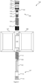
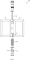
- a dampened hinge assembly 100 comprises a male leaf 106 and a female leaf 107.
- the female leaf 107 comprises a spaced apart first end barrel 108 and a second end barrel 109.
- the first and second end barrels 108, 109 of the female leaf 107 coaxially rotate with respect to a central barrel 110 of the male leaf 106.
- the hinge assembly 100 is typically used in conjunction with the torsion hinge 136 shown in Figure 7 which may employ the same types of leaves 106, 107.
- the torsion hinge 136 provides closure torsion whereas the dampened hinge assembly 100 provides soft closure, end-of-range soft closure and optionally backcheck damping.
- the torsion hinge 136 which is not part of the invention comprises a torsion barrel 137 which comprises a plurality of radial ports 139 through which a pin interlocks through an external aperture 140 to fix the torsion barrel 136 once wound.
- a torsion spring 109 acts on the torsion barrel 137 for torsion closure.
- an axial shaft 119 is fixed to the second end barrel 109 of the female leaf 107 at a proximal end of the axial shaft 119.
- the axial shaft 119 has a distally helicoidally threaded spindle 120.
- a shaft stay 116 may interface the second end barrel 109 and the shaft 119.
- the shaft stay 116 may comprise exterior longitudinal threading which is slidably and non-rotatably engaged by matching longitudinal threading of an interior of the second end barrel 109.
- the shaft stay 116 may comprise an interior bore comprising longitudinal threading within which a proximal end of the shaft 119, comprising matching longitudinal threading, is inserted.
- the assembly 100 further comprises a compression gear 121 slidably retained within the central barrel 110 of the male leaf 106.
- the compression gear 121 comprises external longitudinal threading matching interior longitudinal threading 122 of the central barrel 110.
- the compression gear 121 further comprises a helicoidally threaded bore matching the helicoidal thread of the spindle 120.
- the helicoidal threading of the spindle 120 and the central bore of the compression gear 121 is arranged such that when the leaves 106, 107 move into alignment, the compression gear 121 moves within the central barrel 110 towards the first end barrel 108 and, when the leaves 106, 107 move out of alignment, the compression gear 121 moves towards the second end barrel 109.
- the first end barrel 108 engages a removable end closure 127.
- the removable end closure 127 may comprise a removable end cap 114 and collar 113.
- the removable end cap 114 may comprise threading so as to be able to be unscrewed from the first end barrel 108.
- the removal end 127 has an axial bore 129. As such, in use, the removable end closure 127 can be removed for the installation of an optional elongate compression strut 112.
- the elongate compression strut 112 may comprise a body and a plunger 130.
- the elongate compression strut 112 may be a gas or liquid compressed compression strut 112.
- the compression strut 112 acts as a shock absorber between a central distal bearing face 131 of the compression gear 122 and the removable enclosure 127 across an end-of-range soft closure relative rotational offset range 105 between the leaves 106, 107, typically within the last 30° of closure. When outside this range, the compression strut 112 does not contact the central distal bearing face 131 of the compression gear 122.
- the compression gear 122 defines a peripheral distal bearing face 125 and the removable enclosure defines an oppositely facing peripheral bearing face 126.
- the removable enclosure 127 can be removed in use for the installation of an optional helicoidal compression spring 111 coaxially with respect to the axial bore 129.
- the helicoidal compression spring 111 acts between the peripheral distal bearing face 125 of the compression gear 121 and the oppositely facing peripheral bearing face 126 of the removable enclosure 127 across a soft closure relative offset range 104 between the leaves 106, 107.
- Figure 5 illustrates the installation of the compression strut 112 to only provide only the end-of-range soft closure action 105.
- Figure 6 illustrates the installation of the helicoidal compression spring 111 only to provide only the soft closure action 104.
- Figure 4 illustrates the coaxial installation of both of the compression strut 112 and the helicoidal idle compression spring 112 to provide both soft closure 104 and end-of-range soft closure 105.
- the assembly 100 may further comprise a second removable closure 128 engaged by the second end barrel 109.
- the second removable closure 128 may comprise an enclosure cap 115 which can be removed to slide out the shaft stay 116.
- the second removable enclosure 128 may further comprise a female shaft stay 133 and Teflon TM bushing 132.
- the second removable enclosure 128 can be removed in use for the installation of an optional backcheck helicoidal compression spring 134 to provide backcheck action 103.
- the compression gear 121 may define a proximal peripheral bearing face 124 and the second end closure 128 may comprise an oppositely facing peripheral bearing face 123 (which may be defined by a formation in the shaft 119, by a washer 135 or the like) which cooperate to compress the backcheck helicoidal compression spring 134 therebetween.
Landscapes
- Engineering & Computer Science (AREA)
- Mechanical Engineering (AREA)
- Structural Engineering (AREA)
- Closing And Opening Devices For Wings, And Checks For Wings (AREA)
- Hinges (AREA)
Claims (10)
- Un ensemble de charnière amorti (100) comprenant un vantail mâle (106) et un vantail femelle (107), le vantail femelle (107) comprenant des premier et second barillets d'extrémité espacés (108, 109) tournant de manière coaxiale par rapport à un barillet central (110) du vantail mâle (106) entre eux, un arbre axial (119) fixé au deuxième barillet d'extrémité (109) du vantail femelle (107) au niveau d'une extrémité proximale de l'arbre axial (119), l'arbre axial (119 ) comportant une tige distale à filetage hélicoïdal (120), un engrenage de compression (121) ayant un alésage fileté de manière hélicoïdale correspondant au filetage hélicoïdal de la tige (120), l'engrenage de compression (121) ayant un filetage longitudinal externe correspondant au filetage longitudinal intérieur (122) du barillet central (110), dans lequel un filetage hélicoïdal entre les vantaux (106, 107) cause l'engrenage de compression (121) à se déplacer vers le premier barillet d'extrémité (108) lorsque les vantaux (106, 107) se déplacent en alignement et vers le second le barillet d'extrémité (109) lorsque les vantaux (106, 107) se désalignent et dans lequel le premier barillet d'extrémité (108) s'engage dans une première fermeture d'extrémité amovible (127) ayant un alésage axial (129), une entretoise de compression allongée à fermeture souple de fin de plage (112) et un ressort de compression hélicoïdal à fermeture souple (111), dans lequel la première fermeture d'extrémité amovible (127) pouvant être retirée lors de l'utilisation pour l'installation de l'entretoise de compression allongée à fermeture souple de fin de plage (112). ) à l'intérieur de l'alésage utilisé pour s'appuyer contre une face d'appui distale centrale (131) de l'engrenage de compression (121) pour agir entre la première fermeture d'extrémité amovible (127) et l'engrenage de compression (121) sur une plage de décalage de rotation relative de fermeture en douceur de fin de plage (105)
entre les vantaux (106, 107) ; et l'engrenage de compression (121) définit une face d'appui distale périphérique (125) et la première fermeture d'extrémité amovible (127) définit une face d'appui périphérique opposée (126) de telle sorte que la première fermeture d'extrémité amovible (127) peut être retirée lors de l'utilisation pour l'installation du ressort de compression hélicoïdal à fermeture douce (111) de manière coaxiale par rapport à l'alésage axial (129) pour agir entre la face d'appui distale périphérique (125) et la face d'appui périphérique opposée (126) sur une plage de décalage de rotation relative de fermeture douce (104) entre les vantaux (106, 107), dans lequel l'entretoise de compression allongée à fermeture souple en fin de plage (112) ne rentre pas en contact avec la face d'appui distale centrale (131) de l'engrenage de compression (121) en dehors de la plage de décalage de rotation relative de fermeture douce de fin de plage (105) de sorte que la plage de décalage de la rotation relative de la fermeture douce (104) est supérieure à la plage de décalage de rotation relative de fermeture en douceur de fin de plage (105). - Un ensemble charnière amorti (100) selon la revendication 1, dans lequel la seconde extrémité de barillet (109) s'engage dans une seconde fermeture amovible (128) de telle sorte que la seconde fermeture amovible (128) peut être retirée lors de l'utilisation pour l'installation d'un ressort de compression hélicoïdal (134) autour de la tige pour agir entre une face d'appui proximale périphérique (124) de l'engrenage de compression (121) et la seconde fermeture amovible (128) sur une plage de décalage de rotation relative de contrôle arrière (103) entre les vantaux (106, 107).
- Un ensemble charnière amorti (100) selon la revendication 1, dans lequel la plage de décalage de rotation relative de fermeture en douceur de fin de plage (105) entre les vantaux (106, 107) est inférieure à 30 pi entre les vantaux (106, 107).
- Un ensemble charnière amorti (100) selon la revendication 1, dans lequel la première fermeture d'extrémité de retrait (127) comprend un capuchon d'extrémité amovible (114) et un collier (113), le collier (113) définissant l'alésage axial (129).
- Un ensemble charnière amorti (100) selon la revendication 2, dans lequel la seconde fermeture amovible (128) comprend un support d'arbre (116) comprenant un filetage longitudinal (122) retenu de manière coulissante dans le filetage longitudinal intérieur correspondant (122) du deuxième cylindre d'extrémité (109) et dans lequel le support d'arbre (116) comprend un alésage comprenant un filetage longitudinal (122) à l'intérieur duquel une extrémité proximale de l'arbre (119), comprenant un filetage longitudinal correspondant (122), est retenue.
- Un ensemble de charnière amorti (100) selon la revendication 1, dans lequel le ressort de compression hélicoïdal à fermeture douce (111) est retenu de manière coaxiale par rapport à l'entretoise de compression allongée à fermeture douce d'extrémité de plage (112).
- Un ensemble de charnière amorti (100) selon la revendication 2, dans lequel le ressort de compression hélicoïdal de contrôle anti-retour (134) est retenu de manière coaxiale autour de l'arbre.
- Un procédé de reconfiguration de l'amortissement de fermeture d'une charnière selon la revendication 1, le procédé comprenant le retrait de la première fermeture d'extrémité amovible (127) du premier barillet d'extrémité (108) et insertion d'au moins l'une des entretoises de compression allongés à fermeture souple d'extrémité de plage (112) et le ressort de compression hélicoïdal à fermeture douce (111) via le premier barillet d'extrémité (108) et en remplacement de la fermeture d'extrémité amovible (127).
- Un procédé de reconfiguration de l'amortissement anti-retour d'une charnière selon la revendication 2, le procédé comprenant le retrait de la seconde fermeture d'extrémité amovible (128) du second barillet d'extrémité (109) et l'insertion du ressort de compression hélicoïdal de contrôle anti-retour (134) via le second barillet d'extrémité (109) et remplacement de la seconde fermeture d'extrémité amovible (128).
- Un procédé d'entretien sur place d'une charnière selon la revendication 1, le procédé comprenant le retrait de la première fermeture d'extrémité amovible (127) du premier barillet d'extrémité (108) et remplacement d'au moins d'une parmi les entretoises de compression à fermeture douce allongée d'extrémité de plage (112) et le ressort de compression hélicoïdal à fermeture douce (111) via le premier cylindre d'extrémité (108), et remplacer la première fermeture d'extrémité amovible (127).
Applications Claiming Priority (2)
| Application Number | Priority Date | Filing Date | Title |
|---|---|---|---|
| AU2018901508A AU2018901508A0 (en) | 2018-05-03 | Resistance control hinge apparatus | |
| PCT/AU2019/050398 WO2019210364A1 (fr) | 2018-05-03 | 2019-05-02 | Ensemble charnière amorti |
Publications (4)
| Publication Number | Publication Date |
|---|---|
| EP3735505A1 EP3735505A1 (fr) | 2020-11-11 |
| EP3735505A4 EP3735505A4 (fr) | 2021-09-08 |
| EP3735505B1 true EP3735505B1 (fr) | 2024-04-17 |
| EP3735505C0 EP3735505C0 (fr) | 2024-04-17 |
Family
ID=68386853
Family Applications (1)
| Application Number | Title | Priority Date | Filing Date |
|---|---|---|---|
| EP19796662.5A Active EP3735505B1 (fr) | 2018-05-03 | 2019-05-02 | Ensemble charnière amorti |
Country Status (9)
| Country | Link |
|---|---|
| US (1) | US11401744B2 (fr) |
| EP (1) | EP3735505B1 (fr) |
| JP (1) | JP7320858B2 (fr) |
| CN (1) | CN112041528B (fr) |
| AU (1) | AU2019262093B2 (fr) |
| CA (1) | CA3097917A1 (fr) |
| GB (1) | GB2584053B (fr) |
| NZ (1) | NZ769217A (fr) |
| WO (1) | WO2019210364A1 (fr) |
Families Citing this family (8)
| Publication number | Priority date | Publication date | Assignee | Title |
|---|---|---|---|---|
| EP4111022B1 (fr) * | 2020-02-28 | 2024-10-09 | Locinox | Charnière à amortissement hydraulique pour articuler un élément de fermeture sur un support |
| EP4111023B1 (fr) * | 2020-02-28 | 2025-06-18 | Locinox | Amortisseur pour amortir un mouvement de fermeture d'un système de fermeture |
| AU2021271942C1 (en) * | 2020-05-11 | 2026-02-26 | Brolock Pty Ltd | A hinge |
| CN213540043U (zh) * | 2020-09-22 | 2021-06-25 | 肇庆市高要区兆高金属科技有限公司 | 一种自闭液压缓冲合页 |
| CA3211367A1 (fr) * | 2021-04-21 | 2022-10-27 | Scott Cosby | Ameliorations apportees a des charnieres ou composants similaires |
| CN114465368A (zh) * | 2022-01-15 | 2022-05-10 | 深圳市智高翔科技发展有限公司 | 一种多合一无线充电器 |
| CN116221262B (zh) * | 2022-11-15 | 2024-05-31 | 青岛大学 | 阻尼连接器 |
| WO2025100484A1 (fr) * | 2023-11-07 | 2025-05-15 | スガツネ工業株式会社 | Charnière équipée d'un ressort |
Family Cites Families (33)
| Publication number | Priority date | Publication date | Assignee | Title |
|---|---|---|---|---|
| GB427551A (en) | 1934-09-28 | 1935-04-26 | James Sidney Adams | Improvements in and connected with door checks |
| JPS49127443A (fr) * | 1973-04-10 | 1974-12-06 | ||
| US4100646A (en) * | 1977-02-28 | 1978-07-18 | Schubeis E I E | Self-closing hinge |
| ES295448Y (es) | 1986-06-25 | 1987-09-01 | Zeljko Bebek Vuksic | Bisagra de resorte con amortiguador, perfeccionada |
| US5572768A (en) * | 1994-04-13 | 1996-11-12 | Enidine Incorporated | Door closer |
| US6205619B1 (en) * | 1998-09-17 | 2001-03-27 | Jang Jong-Bok | Hydraulic automatic-shock-absorbing hinge device |
| CN2358178Y (zh) | 1998-10-20 | 2000-01-12 | 丁明哲 | 缓冲回复门轴 |
| EP1342875A1 (fr) * | 2002-03-07 | 2003-09-10 | Fu Luong Hi-Tech Co Ltd | Charnière avec un élément de rappel pour fermer automatiquement une porte |
| KR20030075806A (ko) * | 2002-03-20 | 2003-09-26 | 주식회사 아이크 | 도어 개폐장치 |
| WO2004097296A2 (fr) * | 2003-04-30 | 2004-11-11 | Ebara Corporation | Appareil d'acheminement de matiere combustible, appareil et procede de gazeification de matiere combustible |
| KR200361299Y1 (ko) | 2004-06-09 | 2004-09-07 | 조선제 | 도어 닫음 장치 |
| KR101071909B1 (ko) * | 2004-09-03 | 2011-10-11 | 이미재 | 유압식 완충경첩 |
| DE102006019548A1 (de) * | 2006-04-27 | 2007-11-08 | SWS Gesellschaft für Glasbaubeschläge mbH | Scharnier mit hydraulischer Dämpfung |
| US8015665B2 (en) * | 2008-04-25 | 2011-09-13 | Pan Jiaoting | Spring hinge |
| EP2295693A1 (fr) * | 2009-08-27 | 2011-03-16 | Joseph Talpe | Mécanisme de fermeture de porte |
| IT1400022B1 (it) * | 2010-05-11 | 2013-05-09 | Ind Casearia Silvio Belladelli S R L | Dispositivo chiudiporta |
| CN102561871A (zh) * | 2011-12-02 | 2012-07-11 | 浙江工业大学 | 张力与速度调节分离的自动闭门铰链 |
| UA115452C2 (uk) * | 2012-10-04 | 2017-11-10 | Ін Енд Тек С.Р.Л. | Завісовий пристрій для дверей, віконниць і подібного |
| UA115453C2 (uk) * | 2012-10-04 | 2017-11-10 | Ін Енд Тек С.Р.Л. | Завісовий пристрій для дверей, віконниць і подібного |
| KR20140006326U (ko) | 2013-06-10 | 2014-12-18 | 박정호 | 토크 조절이 용이한 힌지 어셈블리 |
| JP2015078723A (ja) | 2013-10-15 | 2015-04-23 | ヤマハ株式会社 | ヒンジ構造 |
| CN105003148A (zh) * | 2014-04-27 | 2015-10-28 | 邵国忠 | 自动闭门调速合页 |
| CN104895436B (zh) * | 2015-06-08 | 2017-04-12 | 潘约章 | 一种多功能液压缓冲合页 |
| CN107780740B (zh) * | 2016-08-31 | 2020-03-31 | 赵芬 | 高密封式门能调节角度定位及自闭铰链 |
| CN205135204U (zh) * | 2015-10-15 | 2016-04-06 | 温州欧德门控科技发展有限公司 | 闭门器 |
| US10626651B2 (en) | 2015-12-10 | 2020-04-21 | Jong Bok CHANG | Hinge for opening/closing door |
| EP3342965A1 (fr) * | 2016-12-27 | 2018-07-04 | Locinox | Charnière à fermeture automatique avec amortissement hydraulique |
| PL3563021T3 (pl) * | 2016-12-27 | 2021-08-23 | Locinox | Siłownik tłumiony hydraulicznie |
| US20180238092A1 (en) * | 2017-02-20 | 2018-08-23 | Victory Sales and Distribution, LLC. | Combined Door Hinge with Variable Hydraulic Damping and Stopper Device Performance |
| DE102018110723A1 (de) * | 2018-05-04 | 2019-11-07 | Brose Fahrzeugteile Gmbh & Co. Kommanditgesellschaft, Bamberg | Antriebsanordnung für ein Verschlusselement eines Kraftfahrzeugs |
| WO2020020093A1 (fr) * | 2018-07-23 | 2020-01-30 | 赵芬 | Structure de lame de charnière |
| DE102018125473B4 (de) * | 2018-10-15 | 2022-07-28 | Dormakaba Deutschland Gmbh | Durchgangssperre sowie ein Verfahren zur Herstellung einer Durchgangssperre |
| TWI722441B (zh) * | 2019-05-27 | 2021-03-21 | 陳旺松 | 組合式鉸鏈及液壓裝置 |
-
2019
- 2019-05-02 JP JP2021510494A patent/JP7320858B2/ja active Active
- 2019-05-02 CA CA3097917A patent/CA3097917A1/fr active Pending
- 2019-05-02 WO PCT/AU2019/050398 patent/WO2019210364A1/fr not_active Ceased
- 2019-05-02 CN CN201980008606.0A patent/CN112041528B/zh active Active
- 2019-05-02 NZ NZ769217A patent/NZ769217A/en unknown
- 2019-05-02 EP EP19796662.5A patent/EP3735505B1/fr active Active
- 2019-05-02 AU AU2019262093A patent/AU2019262093B2/en active Active
- 2019-05-02 GB GB2012222.2A patent/GB2584053B/en active Active
- 2019-05-02 US US16/968,844 patent/US11401744B2/en active Active
Also Published As
| Publication number | Publication date |
|---|---|
| GB2584053A8 (en) | 2020-11-25 |
| EP3735505A4 (fr) | 2021-09-08 |
| GB2584053A (en) | 2020-11-18 |
| US20210017798A1 (en) | 2021-01-21 |
| GB2584053B (en) | 2022-07-06 |
| CN112041528B (zh) | 2022-07-19 |
| AU2019262093B2 (en) | 2020-05-07 |
| GB202012222D0 (en) | 2020-09-16 |
| WO2019210364A1 (fr) | 2019-11-07 |
| JP7320858B2 (ja) | 2023-08-04 |
| JP2021522434A (ja) | 2021-08-30 |
| EP3735505A1 (fr) | 2020-11-11 |
| CA3097917A1 (fr) | 2019-11-07 |
| EP3735505C0 (fr) | 2024-04-17 |
| CN112041528A (zh) | 2020-12-04 |
| AU2019262093A1 (en) | 2020-04-16 |
| NZ769217A (en) | 2026-02-27 |
| US11401744B2 (en) | 2022-08-02 |
Similar Documents
| Publication | Publication Date | Title |
|---|---|---|
| EP3735505B1 (fr) | Ensemble charnière amorti | |
| US11268312B2 (en) | Combined door hinge with variable hydraulic damping and stopper device performance | |
| US5802670A (en) | Door closer | |
| DE102015015170B3 (de) | Zylinder-Kolben-Einheit mit Ausgleichsdichtelement | |
| US20150211278A1 (en) | Door closer with tri-lobe pinion | |
| EP0251972A2 (fr) | Charnière à ressort et à amortisseur | |
| DE102011007401A1 (de) | Tür-Anordnung | |
| CN111194388B (zh) | 用于可相对于彼此移动的部件的流体减振器,包括在缸中可移动地引导的活塞 | |
| EP0757742B1 (fr) | Ferme-porte automatique et son procede de montage | |
| US11781359B2 (en) | Small bulkiness hinge | |
| US4190925A (en) | Door-closer and hinge combination | |
| CN101975006A (zh) | 一种多功能地弹簧 | |
| EP2518252A2 (fr) | Ferme-porte | |
| EP2839100A1 (fr) | Ferme-porte | |
| EP2243573A2 (fr) | Tige de piston avec tourillion montable | |
| DE102016208099A1 (de) | Antrieb für eine tür | |
| DE10321351A1 (de) | Einrichtung zur amplitudenabhängigen Dämpfung von Stößen | |
| EP2518251A2 (fr) | Ferme-porte | |
| EP0056256A2 (fr) | Ferme-porte | |
| KR200213553Y1 (ko) | 유압식/스프링식 도어클로저를 구비한 도어 | |
| CN201326335Y (zh) | 带有阻尼器的铰链 | |
| KR200271646Y1 (ko) | 경첩형 도어개폐장치 | |
| KR200388916Y1 (ko) | 도어 개폐 완충 장치 | |
| DE102011110672B4 (de) | Schwingungsdämpfer für Fahrzeuge | |
| DE102008030361A1 (de) | Wankstabilisatorsystem sowie Torsionsmotor zur Verstellung eines aktiven Wankstabilisators |
Legal Events
| Date | Code | Title | Description |
|---|---|---|---|
| STAA | Information on the status of an ep patent application or granted ep patent |
Free format text: STATUS: THE INTERNATIONAL PUBLICATION HAS BEEN MADE |
|
| PUAI | Public reference made under article 153(3) epc to a published international application that has entered the european phase |
Free format text: ORIGINAL CODE: 0009012 |
|
| STAA | Information on the status of an ep patent application or granted ep patent |
Free format text: STATUS: REQUEST FOR EXAMINATION WAS MADE |
|
| 17P | Request for examination filed |
Effective date: 20200806 |
|
| AK | Designated contracting states |
Kind code of ref document: A1 Designated state(s): AL AT BE BG CH CY CZ DE DK EE ES FI FR GB GR HR HU IE IS IT LI LT LU LV MC MK MT NL NO PL PT RO RS SE SI SK SM TR |
|
| AX | Request for extension of the european patent |
Extension state: BA ME |
|
| DAV | Request for validation of the european patent (deleted) | ||
| DAX | Request for extension of the european patent (deleted) | ||
| A4 | Supplementary search report drawn up and despatched |
Effective date: 20210805 |
|
| RIC1 | Information provided on ipc code assigned before grant |
Ipc: E05D 3/02 20060101ALN20210730BHEP Ipc: E05F 3/02 20060101ALI20210730BHEP Ipc: E05F 1/12 20060101ALI20210730BHEP Ipc: E05D 11/08 20060101ALI20210730BHEP Ipc: E05D 7/086 20060101ALI20210730BHEP Ipc: E05F 3/20 20060101AFI20210730BHEP |
|
| RIC1 | Information provided on ipc code assigned before grant |
Ipc: E05D 3/02 20060101ALN20230929BHEP Ipc: E05F 3/02 20060101ALI20230929BHEP Ipc: E05F 1/12 20060101ALI20230929BHEP Ipc: E05D 11/08 20060101ALI20230929BHEP Ipc: E05D 7/086 20060101ALI20230929BHEP Ipc: E05F 3/20 20060101AFI20230929BHEP |
|
| GRAP | Despatch of communication of intention to grant a patent |
Free format text: ORIGINAL CODE: EPIDOSNIGR1 |
|
| STAA | Information on the status of an ep patent application or granted ep patent |
Free format text: STATUS: GRANT OF PATENT IS INTENDED |
|
| INTG | Intention to grant announced |
Effective date: 20231113 |
|
| GRAS | Grant fee paid |
Free format text: ORIGINAL CODE: EPIDOSNIGR3 |
|
| GRAA | (expected) grant |
Free format text: ORIGINAL CODE: 0009210 |
|
| STAA | Information on the status of an ep patent application or granted ep patent |
Free format text: STATUS: THE PATENT HAS BEEN GRANTED |
|
| AK | Designated contracting states |
Kind code of ref document: B1 Designated state(s): AL AT BE BG CH CY CZ DE DK EE ES FI FR GR HR HU IE IS IT LI LT LU LV MC MK MT NL NO PL PT RO RS SE SI SK SM TR |
|
| RBV | Designated contracting states (corrected) |
Designated state(s): AL AT BE BG CH CY CZ DE DK EE ES FI FR GR HR HU IE IS IT LI LT LU LV MC MK MT NL NO PL PT RO RS SE SI SK SM TR |
|
| REG | Reference to a national code |
Ref country code: CH Ref legal event code: EP |
|
| REG | Reference to a national code |
Ref country code: IE Ref legal event code: FG4D Ref country code: DE Ref legal event code: R096 Ref document number: 602019050526 Country of ref document: DE |
|
| U01 | Request for unitary effect filed |
Effective date: 20240517 |
|
| U07 | Unitary effect registered |
Designated state(s): AT BE BG DE DK EE FI FR IT LT LU LV MT NL PT SE SI Effective date: 20240528 |
|
| U20 | Renewal fee for the european patent with unitary effect paid |
Year of fee payment: 6 Effective date: 20240524 |
|
| PG25 | Lapsed in a contracting state [announced via postgrant information from national office to epo] |
Ref country code: IS Free format text: LAPSE BECAUSE OF FAILURE TO SUBMIT A TRANSLATION OF THE DESCRIPTION OR TO PAY THE FEE WITHIN THE PRESCRIBED TIME-LIMIT Effective date: 20240817 |
|
| PG25 | Lapsed in a contracting state [announced via postgrant information from national office to epo] |
Ref country code: HR Free format text: LAPSE BECAUSE OF FAILURE TO SUBMIT A TRANSLATION OF THE DESCRIPTION OR TO PAY THE FEE WITHIN THE PRESCRIBED TIME-LIMIT Effective date: 20240417 |
|
| PG25 | Lapsed in a contracting state [announced via postgrant information from national office to epo] |
Ref country code: GR Free format text: LAPSE BECAUSE OF FAILURE TO SUBMIT A TRANSLATION OF THE DESCRIPTION OR TO PAY THE FEE WITHIN THE PRESCRIBED TIME-LIMIT Effective date: 20240718 |
|
| PG25 | Lapsed in a contracting state [announced via postgrant information from national office to epo] |
Ref country code: ES Free format text: LAPSE BECAUSE OF FAILURE TO SUBMIT A TRANSLATION OF THE DESCRIPTION OR TO PAY THE FEE WITHIN THE PRESCRIBED TIME-LIMIT Effective date: 20240417 |
|
| PG25 | Lapsed in a contracting state [announced via postgrant information from national office to epo] |
Ref country code: PL Free format text: LAPSE BECAUSE OF FAILURE TO SUBMIT A TRANSLATION OF THE DESCRIPTION OR TO PAY THE FEE WITHIN THE PRESCRIBED TIME-LIMIT Effective date: 20240417 |
|
| PG25 | Lapsed in a contracting state [announced via postgrant information from national office to epo] |
Ref country code: PL Free format text: LAPSE BECAUSE OF FAILURE TO SUBMIT A TRANSLATION OF THE DESCRIPTION OR TO PAY THE FEE WITHIN THE PRESCRIBED TIME-LIMIT Effective date: 20240417 Ref country code: NO Free format text: LAPSE BECAUSE OF FAILURE TO SUBMIT A TRANSLATION OF THE DESCRIPTION OR TO PAY THE FEE WITHIN THE PRESCRIBED TIME-LIMIT Effective date: 20240717 Ref country code: IS Free format text: LAPSE BECAUSE OF FAILURE TO SUBMIT A TRANSLATION OF THE DESCRIPTION OR TO PAY THE FEE WITHIN THE PRESCRIBED TIME-LIMIT Effective date: 20240817 Ref country code: HR Free format text: LAPSE BECAUSE OF FAILURE TO SUBMIT A TRANSLATION OF THE DESCRIPTION OR TO PAY THE FEE WITHIN THE PRESCRIBED TIME-LIMIT Effective date: 20240417 Ref country code: GR Free format text: LAPSE BECAUSE OF FAILURE TO SUBMIT A TRANSLATION OF THE DESCRIPTION OR TO PAY THE FEE WITHIN THE PRESCRIBED TIME-LIMIT Effective date: 20240718 Ref country code: ES Free format text: LAPSE BECAUSE OF FAILURE TO SUBMIT A TRANSLATION OF THE DESCRIPTION OR TO PAY THE FEE WITHIN THE PRESCRIBED TIME-LIMIT Effective date: 20240417 Ref country code: RS Free format text: LAPSE BECAUSE OF FAILURE TO SUBMIT A TRANSLATION OF THE DESCRIPTION OR TO PAY THE FEE WITHIN THE PRESCRIBED TIME-LIMIT Effective date: 20240717 |
|
| REG | Reference to a national code |
Ref country code: CH Ref legal event code: PL |
|
| REG | Reference to a national code |
Ref country code: DE Ref legal event code: R097 Ref document number: 602019050526 Country of ref document: DE |
|
| PG25 | Lapsed in a contracting state [announced via postgrant information from national office to epo] |
Ref country code: CZ Free format text: LAPSE BECAUSE OF FAILURE TO SUBMIT A TRANSLATION OF THE DESCRIPTION OR TO PAY THE FEE WITHIN THE PRESCRIBED TIME-LIMIT Effective date: 20240417 |
|
| PG25 | Lapsed in a contracting state [announced via postgrant information from national office to epo] |
Ref country code: SK Free format text: LAPSE BECAUSE OF FAILURE TO SUBMIT A TRANSLATION OF THE DESCRIPTION OR TO PAY THE FEE WITHIN THE PRESCRIBED TIME-LIMIT Effective date: 20240417 Ref country code: RO Free format text: LAPSE BECAUSE OF FAILURE TO SUBMIT A TRANSLATION OF THE DESCRIPTION OR TO PAY THE FEE WITHIN THE PRESCRIBED TIME-LIMIT Effective date: 20240417 |
|
| PG25 | Lapsed in a contracting state [announced via postgrant information from national office to epo] |
Ref country code: SM Free format text: LAPSE BECAUSE OF FAILURE TO SUBMIT A TRANSLATION OF THE DESCRIPTION OR TO PAY THE FEE WITHIN THE PRESCRIBED TIME-LIMIT Effective date: 20240417 |
|
| PG25 | Lapsed in a contracting state [announced via postgrant information from national office to epo] |
Ref country code: SM Free format text: LAPSE BECAUSE OF FAILURE TO SUBMIT A TRANSLATION OF THE DESCRIPTION OR TO PAY THE FEE WITHIN THE PRESCRIBED TIME-LIMIT Effective date: 20240417 Ref country code: SK Free format text: LAPSE BECAUSE OF FAILURE TO SUBMIT A TRANSLATION OF THE DESCRIPTION OR TO PAY THE FEE WITHIN THE PRESCRIBED TIME-LIMIT Effective date: 20240417 Ref country code: RO Free format text: LAPSE BECAUSE OF FAILURE TO SUBMIT A TRANSLATION OF THE DESCRIPTION OR TO PAY THE FEE WITHIN THE PRESCRIBED TIME-LIMIT Effective date: 20240417 Ref country code: CZ Free format text: LAPSE BECAUSE OF FAILURE TO SUBMIT A TRANSLATION OF THE DESCRIPTION OR TO PAY THE FEE WITHIN THE PRESCRIBED TIME-LIMIT Effective date: 20240417 Ref country code: CH Free format text: LAPSE BECAUSE OF NON-PAYMENT OF DUE FEES Effective date: 20240531 Ref country code: MC Free format text: LAPSE BECAUSE OF FAILURE TO SUBMIT A TRANSLATION OF THE DESCRIPTION OR TO PAY THE FEE WITHIN THE PRESCRIBED TIME-LIMIT Effective date: 20240417 |
|
| PLBE | No opposition filed within time limit |
Free format text: ORIGINAL CODE: 0009261 |
|
| STAA | Information on the status of an ep patent application or granted ep patent |
Free format text: STATUS: NO OPPOSITION FILED WITHIN TIME LIMIT |
|
| 26N | No opposition filed |
Effective date: 20250120 |
|
| U20 | Renewal fee for the european patent with unitary effect paid |
Year of fee payment: 7 Effective date: 20250423 |
|
| PG25 | Lapsed in a contracting state [announced via postgrant information from national office to epo] |
Ref country code: CY Free format text: LAPSE BECAUSE OF FAILURE TO SUBMIT A TRANSLATION OF THE DESCRIPTION OR TO PAY THE FEE WITHIN THE PRESCRIBED TIME-LIMIT; INVALID AB INITIO Effective date: 20190502 |
|
| PG25 | Lapsed in a contracting state [announced via postgrant information from national office to epo] |
Ref country code: HU Free format text: LAPSE BECAUSE OF FAILURE TO SUBMIT A TRANSLATION OF THE DESCRIPTION OR TO PAY THE FEE WITHIN THE PRESCRIBED TIME-LIMIT; INVALID AB INITIO Effective date: 20190502 |
|
| PGFP | Annual fee paid to national office [announced via postgrant information from national office to epo] |
Ref country code: IE Payment date: 20260318 Year of fee payment: 8 |
|
| U20 | Renewal fee for the european patent with unitary effect paid |
Year of fee payment: 8 Effective date: 20260317 |