EP3829011B1 - Gasisolierte schaltanlage - Google Patents
Gasisolierte schaltanlage Download PDFInfo
- Publication number
- EP3829011B1 EP3829011B1 EP19840150.7A EP19840150A EP3829011B1 EP 3829011 B1 EP3829011 B1 EP 3829011B1 EP 19840150 A EP19840150 A EP 19840150A EP 3829011 B1 EP3829011 B1 EP 3829011B1
- Authority
- EP
- European Patent Office
- Prior art keywords
- power receiving
- bushings
- gas
- bushing
- lead
- Prior art date
- Legal status (The legal status is an assumption and is not a legal conclusion. Google has not performed a legal analysis and makes no representation as to the accuracy of the status listed.)
- Active
Links
Images



Classifications
-
- H—ELECTRICITY
- H02—GENERATION; CONVERSION OR DISTRIBUTION OF ELECTRIC POWER
- H02B—BOARDS, SUBSTATIONS OR SWITCHING ARRANGEMENTS FOR THE SUPPLY OR DISTRIBUTION OF ELECTRIC POWER
- H02B13/00—Arrangement of switchgear in which switches are enclosed in, or structurally associated with, a casing, e.g. cubicle
- H02B13/02—Arrangement of switchgear in which switches are enclosed in, or structurally associated with, a casing, e.g. cubicle with metal casing
- H02B13/035—Gas-insulated switchgear
- H02B13/0358—Connections to in or out conductors
-
- H—ELECTRICITY
- H02—GENERATION; CONVERSION OR DISTRIBUTION OF ELECTRIC POWER
- H02B—BOARDS, SUBSTATIONS OR SWITCHING ARRANGEMENTS FOR THE SUPPLY OR DISTRIBUTION OF ELECTRIC POWER
- H02B13/00—Arrangement of switchgear in which switches are enclosed in, or structurally associated with, a casing, e.g. cubicle
- H02B13/02—Arrangement of switchgear in which switches are enclosed in, or structurally associated with, a casing, e.g. cubicle with metal casing
- H02B13/035—Gas-insulated switchgear
- H02B13/0352—Gas-insulated switchgear for three phase switchgear
-
- H—ELECTRICITY
- H02—GENERATION; CONVERSION OR DISTRIBUTION OF ELECTRIC POWER
- H02B—BOARDS, SUBSTATIONS OR SWITCHING ARRANGEMENTS FOR THE SUPPLY OR DISTRIBUTION OF ELECTRIC POWER
- H02B13/00—Arrangement of switchgear in which switches are enclosed in, or structurally associated with, a casing, e.g. cubicle
- H02B13/02—Arrangement of switchgear in which switches are enclosed in, or structurally associated with, a casing, e.g. cubicle with metal casing
- H02B13/035—Gas-insulated switchgear
- H02B13/0356—Mounting of monitoring devices, e.g. current transformers
-
- H—ELECTRICITY
- H02—GENERATION; CONVERSION OR DISTRIBUTION OF ELECTRIC POWER
- H02B—BOARDS, SUBSTATIONS OR SWITCHING ARRANGEMENTS FOR THE SUPPLY OR DISTRIBUTION OF ELECTRIC POWER
- H02B13/00—Arrangement of switchgear in which switches are enclosed in, or structurally associated with, a casing, e.g. cubicle
- H02B13/02—Arrangement of switchgear in which switches are enclosed in, or structurally associated with, a casing, e.g. cubicle with metal casing
- H02B13/035—Gas-insulated switchgear
- H02B13/045—Details of casing, e.g. gas tightness
-
- H—ELECTRICITY
- H02—GENERATION; CONVERSION OR DISTRIBUTION OF ELECTRIC POWER
- H02B—BOARDS, SUBSTATIONS OR SWITCHING ARRANGEMENTS FOR THE SUPPLY OR DISTRIBUTION OF ELECTRIC POWER
- H02B5/00—Non-enclosed substations; Substations with enclosed and non-enclosed equipment
- H02B5/06—Non-enclosed substations; Substations with enclosed and non-enclosed equipment gas-insulated
Definitions
- the present disclosure relates to a gas-insulated switchgear.
- a gas-insulated switchgear installed in a substation or the like has a structure in which bushings of three phases, which are overhead wire power receiving parts, are attached to a container in which a circuit breaker, a disconnector, etc., are housed and that is filled with insulating gas.
- the central bushing among the bushings aligned in a line is made high, and the bushings on both sides are inclined.
- arranging all the bushings of the three phases vertically, or attaching at least bushings of two phases to side surfaces of the container, in order to facilitate bushing installation and in order to increase earthquake-resistant strength is disclosed (see Patent Document 1).
- Patent Document 2 discloses a structure, in which a common attachment member for attaching bushings for the three phases to a container is used in order to facilitate the installation of the bushings and the bushings are inclined such that end portions of the bushings are spaced apart from each other in order to ensure insulation distances between the bushings of the three phases.
- Patent documents 3, 4, 5 and 6 disclose other gas-insulated switchgear with different bushing tanks.
- Patent document 6 discloses the preamble of claim 1.
- the conventional gas-insulated switchgear is formed as described above, and, for example, the bushings of the three phases aligned in a line are appropriately installed so as to face in a power receiving lead-in direction, and insulation distances are ensured between lead-in wires to the bushings of the three phases.
- insulation distances cannot be ensured with the bushing arrangement being unchanged in some cases, so that the structure of the overhead wire power receiving parts needs to be changed. Therefore, there is a problem that the power receiving lead-in direction cannot be easily changed.
- the present disclosure discloses a technology for solving the above-described problems, and an object of the present disclosure is to provide a gas-insulated switchgear having a bushing arrangement that can flexibly respond to a power receiving lead-in direction without changing a structure.
- a gas-insulated switchgear includes: a main body portion in which a switching device is housed; power receiving lead-in bushings of three phases to which conductor portions extended rearward from the main body portion are connected, respectively; and a bushing tank at which the power receiving lead-in bushings of the three phases are provided and in which insulating gas is sealed, wherein an upper surface portion of the bushing tank is formed as a hemispherical portion protruding upward, the power receiving lead-in bushings of the three phases are provided at the hemispherical portion, the power receiving lead-in bushings of the three phases are disposed on the upper surface of the bushing tank at equal intervals in a circumferential direction such that end portions thereof are inclined outward so as to be separated from each other, and one of the power receiving lead-in bushings of the three phases is disposed along a front-rear direction of the main body portion.
- the power receiving lead-in bushings of the three phases are disposed at equal intervals in the circumferential direction such that the end portions thereof are inclined outward so as to be separated from each other, and one of the bushings of the three phases is disposed along the front-rear direction of the main body portion in which the switching device is housed, it is possible to ensure insulation distances without depending on a power receiving lead-in direction, so that it is unnecessary to change the structure of the bushings.
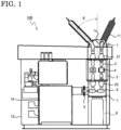
- FIG. 1 is a side cross-sectional view of a gas-insulated switchgear according to Embodiment 1.
- the gas-insulated switchgear 100 includes, within a housing 12, a main body portion 10 in which a gas-insulated switching device (switching device) is housed, and conductor portions 6 extended from the main body portion 10 are connected via cables 3 to power receiving lead-in bushings 11 of three phases (denoted by 11 when described as representatives of 11a, 11b, and 11c) that receive power from the outside.
- the gas-insulated switchgear 100 (C-GIS: cubicle type gas insulated switchgear) is a facility for power transmission and distribution and power reception, is used as, for example, a facility for a substation, and has an overhead wire power receiving structure.
- the gas-insulated switchgear 100 has a configuration in which the main body portion 10 (switching device) housed in the housing 12 is a main component, and a circuit breaker, a grounding switch, a disconnector, an arrester, an instrument transformer, an instrument current transformer, a voltage detector, etc., which are not shown, are integrated in a panel of the main body portion 10.
- An intermediate tank 7 is provided to the rear of the main body portion 10 via a three-phase spacer 9, and a bushing tank 1 is disposed above the intermediate tank 7 via a cable chamber 5 in which the cables 3 are housed.
- the intermediate tank 7 is installed on a base frame 8.
- Three conductor portions 6 for three phases extended horizontally from the main body portion 10 toward the depth side, that is, toward the rear side, extend upward in the vertical direction within the intermediate tank 7 via the three-phase spacer 9 and are connected to the power receiving lead-in bushings 11 via the cables 3.
- bushings 22 are provided as connection portions at an inner upper portion of the intermediate tank 7 in which the insulating gas is sealed, and the conductor portions 6 are connected to the cables 3 via the bushings 22.
- bushings 21 are provided as connection portions at an inner lower portion of the bushing tank 1, and the cables 3 are connected to the power receiving lead-in bushings 11 via the bushings 21.
- the insulating gas is sealed in the bushing tank 1, and an upper surface portion 1a of the bushing tank 1 has a polyhedral structure for providing the power receiving lead-in bushings 11 protruding from the upper surface of the housing 12.
- the polyhedral structure is formed, for example, by welding flat plates so as to have surfaces with predetermined angles at an upper portion of the bushing tank 1 such that each power receiving lead-in bushing 11 is installed in a later-described predetermined direction so as to be inclined outward at a predetermined angle ⁇ from the vertical direction.
- each power receiving lead-in bushing 11 a polymer bushing having an insulating structure in which the outer periphery of a conductor is covered with an epoxy resin, a silicone rubber, or the like is used as each power receiving lead-in bushing 11.
- the cable chamber 5 may be a frame-shaped structure as long as the cables 3 can be housed while being exposed to the atmosphere or in an open space and the intermediate tank 7 and the bushing tank 1 can be supported.
- a current transformer 4 CT may be disposed at an intermediate position of each cable 3.
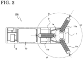
- FIG. 2 is a top view of the gas-insulated switchgear 100.
- the inside of the housing 12 is also transparently shown such that an outline thereof can be seen.
- the power receiving lead-in bushings 11a, 11b, and 11c of the three phases are disposed at the polyhedral structure of the upper surface portion 1a of the bushing tank 1 such that angles ⁇ between the adjacent bushings are equal (substantially 120 degrees), and are disposed such that upper end portions thereof are inclined outward at a predetermined angle so as to be separated from each other.
- the one power receiving lead-in bushing 11a among the three phases is disposed in a direction along the front-rear direction of the main body portion 10 of the gas-insulated switchgear 100 so as to be inclined frontward.
- the other two power receiving lead-in bushings 11b and 11c protrude from the housing 12 portion rearward in the depth direction by a smaller amount, so that the dimension in the depth direction of the gas-insulated switchgear 100 as an apparatus becomes the smallest. This is advantageous, for example, when the installation location of the gas-insulated switchgear 100 is limited.
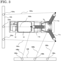
- FIG. 3 is a diagram showing power receiving lead-in directions of the power receiving lead-in bushings 11a, 11b, and 11c of the three phases in FIG. 2 , and illustrates a positional relationship with a power transmission line lead-in tower.
- the drawing shows an example in which two power transmission line lead-in towers 15A and 15B are disposed in different directions.
- a power transmitting portion 15Aa of the power transmission line lead-in tower 15A and a power receiving end portion of the power receiving lead-in bushing 11a are connected by a lead-in wire 16Aa
- a power transmitting portion 15Ab of the power transmission line lead-in tower 15A and a power receiving end portion of the power receiving lead-in bushing 11b are connected by a lead-in wire 16Ab
- a power transmitting portion 15Ac of the power transmission line lead-in tower 15A and a power receiving end portion of the power receiving lead-in bushing 11c are connected by a lead-in wire 16Ac.
- the lead-in wires 16Aa, 16Ab, and 16Ac can ensure insulation distances therebetween.
- a power transmitting portion 15Ba of the power transmission line lead-in tower 15B and the power receiving end portion of the power receiving lead-in bushing 11b are connected by a lead-in wire 16Ba
- a power transmitting portion 15Bb of the power transmission line lead-in tower 15B and the power receiving end portion of the power receiving lead-in bushing 11a are connected by a lead-in wire 16Bb
- a power transmitting portion 15Bc of the power transmission line lead-in tower 15B and the power receiving end portion of the power receiving lead-in bushing 11c are connected by a lead-in wire 16Bc.
- the lead-in wires 16Ba, 16Bb, and 16Bc can ensure insulation distances therebetween.
- the power receiving lead-in bushings 11a, 11b, and 11c are disposed at the upper portion of the bushing tank 1 evenly at intervals of 120 degrees in the circumferential direction so as to be inclined outward relative to each other, so that the end portions of the bushings of the three phases are not aligned in a line. It is possible to ensure insulation distances between the lead-in wires, except for the case where there is a power transmitting portion on an extension in the direction connecting power receiving lead-in bushings of two phases among the power receiving lead-in bushings of the three phases.
- the example in which the power transmission line lead-in towers are present in two different directions, that is, the power receiving lead-in directions are different, has been described, but, in the present embodiment, it is possible to ensure insulation distances between the lead-in wires and receive power, almost without depending on the positions of the power transmission line lead-in towers, or without depending on the positions of the power transmission line lead-in towers by merely rotating the gas-insulated switchgear or the power transmitting portions by about 10 to 20 degrees. Even when the gas-insulated switchgear 100 is installed at a location where an installation space is limited, it is possible to receive power without considering the directions of the power transmission line lead-in towers. Moreover, even when the positional relationship with the power transmission line lead-in tower is changed, that is, the power receiving lead-in direction is changed, it is possible to ensure insulation distances between the lead-in wires and receive power.
- the power receiving lead-in bushings 11a, 11b, and 11c of the three phases are inclined further outward in the direction in which the power receiving lead-in bushings 11a, 11b, and 11c of the three phases are separated from each other, it is easier to ensure insulation distances between the lead-in wires.
- the inclination angle ⁇ exceeds 45 degrees and approaches 90 degrees, it is necessary to ensure insulation distances between the power receiving lead-in bushings 11a, 11b, and 11c and the upper surface of the housing 12.
- the power receiving lead-in bushings 11a, 11b, and 11c of the three phases are opened outward, so that the size of the gas-insulated switchgear 100 as an apparatus is increased.
- the inclination angle ⁇ is preferably in a range of 30 to 60 degrees and is most preferably about 45 degrees (4515 degrees, that is, 40 to 50 degrees) as shown in FIG. 1 .
- the inclination angles of the power receiving lead-in bushings 11a, 11b, and 11c of the three phases are preferably equal to each other.
- FIG. 4 is a top view of another gas-insulated switchgear according to Embodiment 1, showing the power receiving lead-in directions of the power receiving lead-in bushings 11a, 11b, and 11c. Similar to FIG. 3 , the power receiving lead-in bushings 11a, 11b, and 11c of the three phases are disposed at the polyhedral structure of the upper surface portion 1a of the bushing tank 1 such that the angles therebetween are equal (substantially 120 degrees) and the upper end portions thereof are inclined outward so as to be separated from each other. The difference from FIG.
- the one power receiving lead-in bushing 11b among the three phases is disposed in the direction along the front-rear direction of the main body portion 10 of the gas-insulated switchgear 100 so as to be inclined in the rearward direction.
- the bushings are disposed as described above, there is no installed object on an upper portion of the housing 12, so that work can also be performed on the upper surface during maintenance of the apparatus, which is convenient.
- the lead-in wires 16Aa, 16Ab, and 16Ac can ensure insulation distances therebetween, and, regarding power reception from the position of the power transmission line lead-in tower 15B, the lead-in wires 16Ba, 16Bb, and 16Bc can ensure insulation distances therebetween. That is, the same advantageous effects as those in FIG. 3 can be obtained.
- the three-chamber configuration of the intermediate tank 7, the cable chamber 5, and the bushing tank 1 through which the conductor portions 6 are guided to the power receiving lead-in bushings 11 is not limited to the above. These components may be integrated and the insulating gas may be sealed therein. In addition, for example, the cable chamber 5 and the bushing tank 1 may be integrated to form a two-chamber configuration, or the intermediate tank 7 and the cable chamber 5 may be integrated to form a two-chamber configuration.
- FIG. 5 is a side cross-sectional view of still another gas-insulated switchgear 100 according to Embodiment 1.
- This example is an example of a structure in which a cable chamber is not included.
- the conductor portions 6 extended from the main body portion 10 are extended upward in the intermediate tank 7, and are connected to the bushings 21 in the bushing tank 1 via the bushings 22, which are connection portions, at the upper portion of the intermediate tank 7.
- the configuration in which the conductor portions 6 are guided to the power receiving lead-in bushings 11 may be changed as described above.
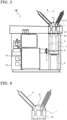
- the bushing tank 1 and the cable chamber 5 can be configured so as to be separable from each other, work for attaching and detaching the cables 3 to the bushings 22 in the bushing tank 1 is work performed in the open space. Therefore, it is possible to separate a portion protruding from the housing 12, as shown in FIG. 6 , and to transport the separated portion.
- Embodiment 1 it is possible not only to ensure insulation distances between the end portions of the power receiving lead-in bushings 11a, 11b, and 11c of the three phases but also to ensure insulation distances between the lead-in wires regardless of the power receiving lead-in directions. That is, it is possible to provide the gas-insulated switchgear 100 as a versatile apparatus for which a structure change does not have to be made for each power receiving lead-in direction. Furthermore, quality improvement, reliability improvement, and cost reduction are achieved.
- Embodiment 2 Although the example in which the upper surface portion 1a of the bushing tank 1 is the polyhedral structure has been described in Embodiment 1, an embodiment according to the invention with a hemispherical structure will be described in Embodiment 2.
- FIG. 7 is a side cross-sectional view of a gas-insulated switchgear 100 according to Embodiment 2.
- the difference from FIG. 1 of Embodiment 1 is that the upper surface portion 1a of the bushing tank 1 is formed as a hemispherical structure.
- the other parts are the same as in FIG. 1 of Embodiment 1, and thus the description thereof is omitted.
- Each power receiving lead-in bushing 11 is installed at the upper surface portion 1a of the bushing tank 1, which is formed as a hemispherical structure, in the predetermined direction described above in Embodiment 1 so as to be inclined outward at a predetermined angle ⁇ from the vertical direction.
- the hemispherical structure can be accurately produced, for example, by casting with a die.
- the bushing tank 1 When the upper surface portion 1a of the bushing tank 1 is formed as a hemispherical structure, it is easier to dispose each power receiving lead-in bushing 11 at a predetermined angle in a predetermined arrangement than with a polyhedral structure, and the bushing tank can be produced with high accuracy. In addition, a thicker structure can be produced than by welding of flat plates or the like, and the strength can also be increased.
- FIG. 8 is a top view of the gas-insulated switchgear 100 in FIG. 7 .
- the power receiving lead-in bushings 11a, 11b, and 11c of the three phases are disposed at the hemispherical structure of the upper surface portion 1a of the bushing tank 1 such that angles ⁇ between the adjacent bushings are equal (substantially 120 degrees), and are disposed such that upper end portions thereof are inclined outward so as to be separated from each other.
- the one power receiving lead-in bushing 11b among the three phases is disposed in a direction along the front-rear direction of the main body portion 10 of the gas-insulated switchgear 100 so as to be inclined frontward.
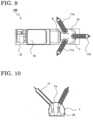
- FIG. 9 is a top view of another gas-insulated switchgear according to Embodiment 2, showing the power receiving lead-in directions of the power receiving lead-in bushings 11a, 11b, and 11c. Similar to FIG. 8 , the power receiving lead-in bushings 11a, 11b, and 11c of the three phases are disposed at the hemispherical structure of the upper surface portion 1a of the bushing tank 1 such that angles therebetween are equal (substantially 120 degrees) and the upper end portions thereof are inclined outward so as to be separated from each other. The difference from FIG.
- This gas-insulated switchgear corresponds to a gas-insulated switchgear obtained when the upper surface portion 1a of the bushing tank 1 in FIG. 4 is formed as a hemispherical structure.
- FIG. 10 is a side cross-sectional view of the bushing tank 1 in FIG. 7 , showing a state where the bushing tank 1 is separated from the cable chamber 5.
- the three-chamber configuration of the intermediate tank 7, the cable chamber 5, and the bushing tank 1 through which the conductor portions 6 are guided to the power receiving lead-in bushings 11 is not limited to the above.
- at least when the cable chamber 5 is exposed to the atmosphere or an open space and the bushing tank 1 and the cable chamber 5 can be configured so as to be separable from each other, work for attaching and detaching the cables 3 to the bushings 22 in the bushing tank 1 is work performed in the open space. Therefore, it is possible to separate a portion protruding from the housing 12 and to transport the separated portion.
- Embodiment 2 similar to Embodiment 1, it is possible not only to ensure insulation distances between the end portions of the respective power receiving lead-in bushings 11a, 11b, and 11c of the three phases but also to ensure insulation distances between the lead-in wires regardless of the power receiving lead-in directions. That is, it is possible to provide the gas-insulated switchgear 100 as a versatile apparatus for which a structure change does not have to be made for each power receiving lead-in direction. Moreover, quality improvement, reliability improvement, and cost reduction are achieved. Furthermore, since the upper surface portion 1a of the bushing tank 1 is formed as a hemispherical structure, it is possible to produce a bushing tank with high accuracy and high strength.
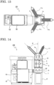
- FIG. 11 is a side cross-sectional view of a gas-insulated switchgear 100 according to Embodiment 3.
- the difference from FIG. 1 of Embodiment 1 is that components disposed to the rear of the main body portion 10 are disposed outside the housing 12. That is, the intermediate tank 7 in which the insulating gas is sealed is provided via the three-phase spacer 9, and the bushing tank 1 in which the insulating gas is sealed is disposed above the intermediate tank 7 via the cable chamber 5 in which the cables 3 are housed. These components are disposed outside the housing 12.
- the intermediate tank 7 is installed on the base frame 8.
- the three-chamber configuration of the intermediate tank 7, the cable chamber 5, and the bushing tank 1 through which the conductor portions 6 are guided to the power receiving lead-in bushings 11 is not limited to the above. These components may be integrated and the insulating gas may be sealed therein. In addition, for example, the cable chamber 5 and the bushing tank 1 may be integrated to form a two-chamber configuration, or the intermediate tank 7 and the cable chamber 5 may be integrated to form a two-chamber configuration.
- FIG. 12 is a top view of the gas-insulated switchgear 100 in FIG. 11 .
- the power receiving lead-in bushings 11a, 11b, and 11c of the three phases are disposed at the polyhedral structure of the upper surface portion 1a of the bushing tank 1 such that angles ⁇ between the adjacent bushings are equal (substantially 120 degrees), and are disposed such that upper end portions thereof are inclined outward at a predetermined angle ⁇ so as to be separated from each other.
- the one power receiving lead-in bushing 11b among the three phases is disposed in a direction along the front-rear direction of the main body portion 10 of the gas-insulated switchgear 100 so as to be inclined in the frontward direction.
- FIG. 13 is a top view of another gas-insulated switchgear according to Embodiment 3, showing the power receiving lead-in directions of the power receiving lead-in bushings 11a, 11b, and 11c. Similar to FIG. 12 , the power receiving lead-in bushings 11a, 11b, and 11c of the three phases are disposed at the polyhedral structure of the upper surface portion 1a of the bushing tank 1 such that angles therebetween are equal (substantially 120 degrees) and the upper end portions thereof are inclined outward at a predetermined angle ⁇ so as to be separated from each other. The difference from FIG.
- the one power receiving lead-in bushing 11b among the three phases is disposed in the direction along the front-rear direction of the main body portion 10 of the gas-insulated switchgear 100 so as to be inclined in the rearward direction.
- This gas-insulated switchgear corresponds to a gas-insulated switchgear obtained when the bushing tank 1, etc., in FIG. 4 are disposed outside the housing 12.
- Embodiment 3 similar to Embodiment 1, it is possible not only to ensure insulation distances between the end portions of the respective power receiving lead-in bushings 11a, 11b, and 11c of the three phases but also to ensure insulation distances between the lead-in wires regardless of the power receiving lead-in directions. That is, it is possible to provide the gas-insulated switchgear 100 as a versatile apparatus for which a structure change does not have to be made for each power receiving lead-in direction. Moreover, quality improvement, reliability improvement, and cost reduction are achieved.
- the cable chamber by making the cable chamber to be exposed to the atmosphere or to be an open space, it is possible to separate the bushing tank 1, on which the respective power receiving lead-in bushings 11 of the three phases are mounted, from the cable chamber, which is connected to the bushing tank 1, and to transport the separated bushing tank 1.
- the intermediate tank 7 and the cable chamber 5 in which the conductor portions 6 extended from the main body portion 10 in the housing 12 are housed are also located outside the housing 12, workability of reassembling after transportation is also improved.
- Embodiment 4 similar to Embodiment 2, an example in which the upper surface portion 1a of the bushing tank 1 is formed as a hemispherical structure will be described.
- FIG. 14 is a side cross-sectional view of a gas-insulated switchgear 100 according to Embodiment 4.
- the difference from Embodiment 3 is that the upper surface portion 1a of the bushing tank 1 is formed as a hemispherical structure.
- the other parts are the same as in Embodiment 3, and thus the description thereof is omitted.
- Each power receiving lead-in bushing 11 is installed at the upper surface portion 1a of the bushing tank 1, which is formed as a hemispherical structure, in the predetermined direction described above so as to be inclined outward at a predetermined angle ⁇ from the vertical direction.
- the hemispherical structure can be accurately produced, for example, by casting with a die.
- the upper surface portion 1a of the bushing tank 1 is formed as a hemispherical structure by casting, it is easier to dispose each power receiving lead-in bushing 11 at a predetermined angle in a predetermined arrangement than with a polyhedral structure, and the bushing tank can be produced with high accuracy.
- its pressure-resistant structure is superior to that of a polyhedral structure, so that the structure can be made thinner to be reduced in weight.
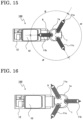
- FIG. 15 is a top view of the gas-insulated switchgear 100 in FIG. 14 .
- the power receiving lead-in bushings 11a, 11b, and 11c of the three phases are disposed at the hemispherical structure of the upper surface portion 1a of the bushing tank 1 such that angles ⁇ between the adjacent bushings are equal (substantially 120 degrees), and are disposed such that upper end portions thereof are inclined outward at a predetermined angle ⁇ so as to be separated from each other.
- the one power receiving lead-in bushing 11b among the three phases is disposed in a direction along the front-rear direction of the main body portion 10 of the gas-insulated switchgear 100 so as to be inclined in the frontward direction.
- FIG. 16 is a top view of another gas-insulated switchgear according to Embodiment 4, showing the power receiving lead-in directions of the power receiving lead-in bushings 11a, 11b, and 11c. Similar to FIG. 15 , the power receiving lead-in bushings 11a, 11b, and 11c of the three phases are disposed at the hemispherical structure of the upper surface portion 1a of the bushing tank 1 such that angles therebetween are equal (substantially 120 degrees) and the upper end portions thereof are inclined outward at a predetermined angle ⁇ so as to be separated from each other. The difference from FIG.
- this gas-insulated switchgear corresponds to a gas-insulated switchgear obtained when the upper surface portion 1a of the bushing tank 1 in FIG. 13 is formed as a hemispherical structure.
- Embodiment 4 the same advantageous effects as those in Embodiments 1 to 3 are achieved. That is, it is possible not only to ensure insulation distances between the end portions of the respective power receiving lead-in bushings 11a, 11b, and 11c of the three phases but also to ensure insulation distances between the lead-in wires regardless of the power receiving lead-in directions. It is possible to provide the gas-insulated switchgear 100 as a versatile apparatus for which a structure change does not have to be made for each power receiving lead-in direction. Moreover, quality improvement, reliability improvement, and cost reduction are achieved. Furthermore, since the upper surface portion 1a of the bushing tank 1 is formed as a hemispherical structure, it is possible to produce a bushing tank with high accuracy and high strength.
- the cable chamber 5 by making the cable chamber 5 to be exposed to the atmosphere or to be an open space, it is possible to separate the bushing tank 1, on which the respective power receiving lead-in bushings 11 of the three phases are mounted, from the cable chamber, which is connected to the bushing tank 1, and to transport the separated bushing tank 1.
- the intermediate tank 7 and the cable chamber 5 in which the conductor portions 6 extended from the main body portion 10 in the housing 12 are housed are also located outside the housing 12, workability of reassembling after transportation is also improved.
Landscapes
- Engineering & Computer Science (AREA)
- Power Engineering (AREA)
- Gas-Insulated Switchgears (AREA)
Claims (6)
- Gasisolierte Schaltanlage (100), mit:einem Hauptkörperteil (10), in dem eine Schalteinrichtung beherbergt ist; leistungsempfangende Zuleitungsdurchführungen (11a, 11b, 11c) von drei Phasen, an welche Leiterabschnitte (6), die rückwärts vom Hauptkörperteil (10) erstreckt sind, jeweils angeschlossen sind; undeinem Durchführungstank (1), an dem die leistungsempfangenden Zuleitungsdurchführungen (11a, 11b, 11c) der drei Phasen bereitgestellt sind und in dem Isoliergas versiegelt ist,dadurch gekennzeichnet, dassein oberer Oberflächenabschnitt (1a) des Durchführungstanks (1) als ein nach oben hervorstehender halbkugelförmiger Abschnitt ausgebildet ist und die leistungsempfangenden Zuleitungsdurchführungen (11a, 11b, 11c) der drei Phasen an dem halbkugelförmigen Abschnitt bereitgestellt sind, unddie leistungsempfangenden Zuleitungsdurchführungen (11a, 11b, 11c) der drei Phasen auf der oberen Oberfläche des Durchführungstanks (1) in gleichen Abständen in einer umlaufenden Richtung angeordnet sind, so dass deren Endabschnitte nach außen geneigt sind, um voneinander getrennt zu sein, und eine der leistungsempfangenden Zuleitungsdurchführungen (11a, 11b, 11c) der drei Phasen entlang einer Vorne-Hinten-Richtung des Hauptkörperteils (10) angeordnet ist.
- Gasisolierte Schaltanlage (100) gemäß Anspruch 1, bei der eine der leistungsempfangenden Zuleitungsdurchführungen (11a,11b,11c) der drei Phasen entlang der Vorne-Hinten-Richtung des Hauptkörperteils (10) angeordnet ist, so dass deren Endabschnitt in eine vordere Richtung des Hauptkörperteils (10) geneigt ist.
- Gasisolierte Schaltanlage (100) gemäß Anspruch 1 oder 2, bei der die leistungsempfangenden Zuleitungsdurchführungen (11a,11b,11c) der drei Phasen nach außen in gleichen Winkeln in einem Bereich von 30 bis 60 Grad von einer vertikalen Richtung geneigt sind.
- Gasisolierte Schaltanlage (100) gemäß einem der Ansprüche 1 bis 3, des Weiteren aufweisend einen Zwischentank (7), der hinter dem Hauptkörperteil (10) bereitgestellt ist und durch den die Leiterabschnitte (6) vom Hauptkörperteil (10) in einen Behälter erstreckt sind, in dem Isoliergas versiegelt ist und der Anschlussabschnitte aufweist, an denen Endabschnitte der Leiterabschnitte (6) angeschlossen sind, wobei
die Anschlussabschnitte des Zwischentanks (7) und Anschlussabschnitte, die im Durchführungstank (1) bereitgestellt sind und an denen die leistungsempfangenden Zuleitungsdurchführungen (11a,11b,11c) der drei Phasen angeschlossen sind, durch Kabel (3) verbunden sind. - Gasisolierte Schaltanlage (100) gemäß Anspruch 4, bei der die Anschlussabschnitte des Zwischentanks (7) und die Anschlussabschnitte des Durchführungstanks (1) mit den Kabeln (3) in einem offenen Raum verbunden sind.
- Gasisolierte Schaltanlage (100) gemäß Anspruch 5, bei der das Hauptkörperteil (10) in einem Gehäuse (12) beherbergt ist und der Zwischentank (7) sowie der Durchführungstank (1) außerhalb des Gehäuses (12) angeordnet sind.
Applications Claiming Priority (2)
| Application Number | Priority Date | Filing Date | Title |
|---|---|---|---|
| JP2018138164 | 2018-07-24 | ||
| PCT/JP2019/012339 WO2020021769A1 (ja) | 2018-07-24 | 2019-03-25 | ガス絶縁スイッチギヤ |
Publications (3)
| Publication Number | Publication Date |
|---|---|
| EP3829011A1 EP3829011A1 (de) | 2021-06-02 |
| EP3829011A4 EP3829011A4 (de) | 2021-08-25 |
| EP3829011B1 true EP3829011B1 (de) | 2024-06-12 |
Family
ID=69181444
Family Applications (1)
| Application Number | Title | Priority Date | Filing Date |
|---|---|---|---|
| EP19840150.7A Active EP3829011B1 (de) | 2018-07-24 | 2019-03-25 | Gasisolierte schaltanlage |
Country Status (5)
| Country | Link |
|---|---|
| US (1) | US11289885B2 (de) |
| EP (1) | EP3829011B1 (de) |
| JP (1) | JP6746004B2 (de) |
| CN (1) | CN112470355B (de) |
| WO (1) | WO2020021769A1 (de) |
Families Citing this family (2)
| Publication number | Priority date | Publication date | Assignee | Title |
|---|---|---|---|---|
| WO2022085145A1 (ja) * | 2020-10-22 | 2022-04-28 | 三菱電機株式会社 | バルブ型ガスフィルタおよびガス絶縁開閉装置 |
| EP4224650B1 (de) * | 2022-02-02 | 2025-12-17 | Hitachi Energy Ltd | Anpassungsmodul für eine gasisolierte schaltanlage |
Family Cites Families (34)
| Publication number | Priority date | Publication date | Assignee | Title |
|---|---|---|---|---|
| US2760033A (en) * | 1952-11-19 | 1956-08-21 | Westinghouse Electric Corp | Circuit interrupter |
| US3073891A (en) * | 1959-07-06 | 1963-01-15 | Mc Graw Edison Co | Rotatable insulating bushing |
| US3214550A (en) * | 1962-05-02 | 1965-10-26 | Westinghouse Electric Corp | Circuit interrupters with crossbars captively related to piston structures |
| US3335245A (en) * | 1966-01-12 | 1967-08-08 | Ite Circuit Breaker Ltd | Combined tank liner interphase barrier for oil circuit breakers |
| JPS5185438A (de) * | 1975-01-16 | 1976-07-27 | Hitachi Ltd | |
| JPS6110407Y2 (de) * | 1978-01-06 | 1986-04-03 | ||
| JPS5930610U (ja) | 1982-08-23 | 1984-02-25 | 日新電機株式会社 | ガス絶縁電気装置 |
| JPS5950516U (ja) * | 1982-09-28 | 1984-04-03 | 日新電機株式会社 | 3相一括形ガス絶縁開閉装置 |
| JPS59191812U (ja) * | 1983-06-03 | 1984-12-19 | 日新電機株式会社 | 箱形開閉装置 |
| JPS6062806A (ja) * | 1983-09-13 | 1985-04-11 | 日新電機株式会社 | 密閉形開閉装置 |
| JPH0626446B2 (ja) * | 1987-10-15 | 1994-04-06 | 日新電機株式会社 | キュービクル形ガス絶縁開閉装置 |
| DE3915699C3 (de) * | 1989-05-13 | 1995-06-14 | Licentia Gmbh | Freiluftdurchführungen für einen Schaltfeld-Container |
| JPH0574106U (ja) * | 1992-03-09 | 1993-10-08 | 株式会社明電舎 | 開閉装置 |
| DE19626002A1 (de) * | 1996-06-28 | 1998-01-08 | Abb Patent Gmbh | Freiluftspannungswandler |
| FR2751799B1 (fr) * | 1996-07-25 | 1998-09-11 | Gec Alsthom T & D Sa | Poste prefabrique pour appareillage electrique, en particulier pour appareillage sous enveloppe metallique |
| JP3482325B2 (ja) * | 1997-09-03 | 2003-12-22 | 三菱電機株式会社 | ガス遮断器 |
| JP3726521B2 (ja) * | 1998-12-14 | 2005-12-14 | 日新電機株式会社 | ブッシング付3相一括形ガス絶縁機器 |
| JP3835036B2 (ja) * | 1999-01-29 | 2006-10-18 | 株式会社日立製作所 | ガス絶縁開閉装置 |
| JP2000232707A (ja) | 1999-02-12 | 2000-08-22 | Meidensha Corp | ガス絶縁開閉装置 |
| DE10014680B4 (de) * | 2000-03-17 | 2008-08-07 | Siemens Ag | Dreiphasig gekapselter Hochspannungs-Leistungsschalter in Freiluftausführung |
| FR2815784B1 (fr) * | 2000-10-20 | 2003-01-17 | Alstom | Poste haute tension hybride a depart opposes en vis a vis, et modules blindes de coupure et d'aiguillage pour un tel poste |
| AU763276B2 (en) * | 2001-02-07 | 2003-07-17 | Hitachi Limited | Gas insulated switchgear |
| CN1231933C (zh) * | 2002-05-31 | 2005-12-14 | 株式会社日立制作所 | 气体绝缘开关装置 |
| KR101003641B1 (ko) * | 2008-09-08 | 2010-12-23 | 엘에스산전 주식회사 | 가스 절연 개폐장치의 3상모선용 가스 구획장치 |
| DE102010018063A1 (de) * | 2010-04-20 | 2011-10-20 | Siemens Aktiengesellschaft | Kapselungsgehäuseabschnitt einer druckgasisolierten Elektroenergieübertragungseinrichtung |
| KR101151989B1 (ko) * | 2010-12-17 | 2012-06-01 | 엘에스산전 주식회사 | 고체절연 부하개폐기의 모선 접속장치 |
| JP5950516B2 (ja) * | 2011-08-31 | 2016-07-13 | 三菱マヒンドラ農機株式会社 | 作業車両 |
| WO2013046737A1 (ja) * | 2011-09-29 | 2013-04-04 | 三菱電機株式会社 | ガス絶縁開閉装置 |
| CN104937793B (zh) * | 2013-01-15 | 2017-04-12 | 三菱电机株式会社 | 气体绝缘开关装置 |
| CN204497572U (zh) * | 2015-04-15 | 2015-07-22 | 山东泰山恒信开关集团有限公司 | 一种hgis设备 |
| CN205377065U (zh) * | 2016-02-23 | 2016-07-06 | 施耐德电气(厦门)开关设备有限公司 | 一种开关柜 |
| CN206293812U (zh) * | 2016-11-04 | 2017-06-30 | 平高集团有限公司 | 一种电连接结构以及气体绝缘金属封闭开关设备 |
| US10355460B2 (en) * | 2017-06-01 | 2019-07-16 | Quanta Associates, L. P. | Switchgear with circuit breaker bay(s) |
| CN112514187A (zh) * | 2018-07-24 | 2021-03-16 | 三菱电机株式会社 | 气体绝缘开关装置 |
-
2019
- 2019-03-25 EP EP19840150.7A patent/EP3829011B1/de active Active
- 2019-03-25 CN CN201980048378.XA patent/CN112470355B/zh active Active
- 2019-03-25 WO PCT/JP2019/012339 patent/WO2020021769A1/ja not_active Ceased
- 2019-03-25 US US17/045,790 patent/US11289885B2/en active Active
- 2019-03-25 JP JP2019542643A patent/JP6746004B2/ja active Active
Also Published As
| Publication number | Publication date |
|---|---|
| WO2020021769A1 (ja) | 2020-01-30 |
| EP3829011A4 (de) | 2021-08-25 |
| CN112470355A (zh) | 2021-03-09 |
| JPWO2020021769A1 (ja) | 2020-08-06 |
| CN112470355B (zh) | 2023-02-03 |
| EP3829011A1 (de) | 2021-06-02 |
| US20210175691A1 (en) | 2021-06-10 |
| US11289885B2 (en) | 2022-03-29 |
| JP6746004B2 (ja) | 2020-08-26 |
Similar Documents
| Publication | Publication Date | Title |
|---|---|---|
| EP2104127B1 (de) | Schaltanlage | |
| US20020104827A1 (en) | Gas insulated switchgear | |
| ES2820900T3 (es) | Instalación de conmutación con aislamiento gaseoso | |
| KR20100017368A (ko) | 고전압 개폐기 | |
| EP3829011B1 (de) | Gasisolierte schaltanlage | |
| EP2833494B1 (de) | Gasisolierte schaltanlage | |
| EP1107408A1 (de) | Gasisolierte Schaltanlage | |
| US5589674A (en) | Metal-encapsulated, gas-insulated switching installation | |
| EP0010564B1 (de) | Gasisolierte Schaltanlage | |
| KR100393262B1 (ko) | 가스절연개폐장치 | |
| EP3280016B1 (de) | Gasisoliertes schaltgetriebe | |
| KR102674085B1 (ko) | 친환경 가스절연 개폐장치용 단로기 | |
| JP6639311B2 (ja) | ガス絶縁開閉装置 | |
| US9165700B2 (en) | Polyphase-compressed-gas-insulated cable entry module having an encapsulation | |
| KR100237585B1 (ko) | 복합형 가스절연 개폐장치 | |
| US20210376577A1 (en) | Bus bar connecting device, switchgear, and method for connecting a bus bar connecting device | |
| JP2021093795A (ja) | ガス絶縁開閉装置 | |
| JPH09200916A (ja) | ガス絶縁開閉装置 | |
| JP2007181321A (ja) | スイッチギヤ | |
| US3315046A (en) | Combination line insulator and cable pothead | |
| JP2000308220A (ja) | ガス絶縁開閉装置 | |
| JP2007159330A (ja) | ガス絶縁開閉装置 | |
| EP0014224A1 (de) | Gasisolierte Schaltanlage | |
| KR20130002158A (ko) | 가스절연개폐장치용 변류기 취부 구조 | |
| JPH0655007B2 (ja) | ガス絶縁開閉装置 |
Legal Events
| Date | Code | Title | Description |
|---|---|---|---|
| STAA | Information on the status of an ep patent application or granted ep patent |
Free format text: STATUS: THE INTERNATIONAL PUBLICATION HAS BEEN MADE |
|
| PUAI | Public reference made under article 153(3) epc to a published international application that has entered the european phase |
Free format text: ORIGINAL CODE: 0009012 |
|
| STAA | Information on the status of an ep patent application or granted ep patent |
Free format text: STATUS: REQUEST FOR EXAMINATION WAS MADE |
|
| 17P | Request for examination filed |
Effective date: 20201015 |
|
| AK | Designated contracting states |
Kind code of ref document: A1 Designated state(s): AL AT BE BG CH CY CZ DE DK EE ES FI FR GB GR HR HU IE IS IT LI LT LU LV MC MK MT NL NO PL PT RO RS SE SI SK SM TR |
|
| A4 | Supplementary search report drawn up and despatched |
Effective date: 20210726 |
|
| RIC1 | Information provided on ipc code assigned before grant |
Ipc: H02B 13/035 20060101AFI20210720BHEP Ipc: H02B 1/20 20060101ALI20210720BHEP Ipc: H02B 13/045 20060101ALI20210720BHEP |
|
| DAV | Request for validation of the european patent (deleted) | ||
| DAX | Request for extension of the european patent (deleted) | ||
| GRAP | Despatch of communication of intention to grant a patent |
Free format text: ORIGINAL CODE: EPIDOSNIGR1 |
|
| STAA | Information on the status of an ep patent application or granted ep patent |
Free format text: STATUS: GRANT OF PATENT IS INTENDED |
|
| RIC1 | Information provided on ipc code assigned before grant |
Ipc: H02B 13/045 20060101ALI20220211BHEP Ipc: H02B 13/035 20060101AFI20220211BHEP |
|
| INTG | Intention to grant announced |
Effective date: 20220302 |
|
| GRAJ | Information related to disapproval of communication of intention to grant by the applicant or resumption of examination proceedings by the epo deleted |
Free format text: ORIGINAL CODE: EPIDOSDIGR1 |
|
| STAA | Information on the status of an ep patent application or granted ep patent |
Free format text: STATUS: REQUEST FOR EXAMINATION WAS MADE |
|
| INTC | Intention to grant announced (deleted) | ||
| STAA | Information on the status of an ep patent application or granted ep patent |
Free format text: STATUS: EXAMINATION IS IN PROGRESS |
|
| 17Q | First examination report despatched |
Effective date: 20220826 |
|
| GRAP | Despatch of communication of intention to grant a patent |
Free format text: ORIGINAL CODE: EPIDOSNIGR1 |
|
| STAA | Information on the status of an ep patent application or granted ep patent |
Free format text: STATUS: GRANT OF PATENT IS INTENDED |
|
| INTG | Intention to grant announced |
Effective date: 20240129 |
|
| GRAS | Grant fee paid |
Free format text: ORIGINAL CODE: EPIDOSNIGR3 |
|
| GRAA | (expected) grant |
Free format text: ORIGINAL CODE: 0009210 |
|
| STAA | Information on the status of an ep patent application or granted ep patent |
Free format text: STATUS: THE PATENT HAS BEEN GRANTED |
|
| AK | Designated contracting states |
Kind code of ref document: B1 Designated state(s): AL AT BE BG CH CY CZ DE DK EE ES FI FR GB GR HR HU IE IS IT LI LT LU LV MC MK MT NL NO PL PT RO RS SE SI SK SM TR |
|
| REG | Reference to a national code |
Ref country code: GB Ref legal event code: FG4D |
|
| REG | Reference to a national code |
Ref country code: CH Ref legal event code: EP |
|
| REG | Reference to a national code |
Ref country code: IE Ref legal event code: FG4D |
|
| REG | Reference to a national code |
Ref country code: DE Ref legal event code: R096 Ref document number: 602019053680 Country of ref document: DE |
|
| PG25 | Lapsed in a contracting state [announced via postgrant information from national office to epo] |
Ref country code: BG Free format text: LAPSE BECAUSE OF FAILURE TO SUBMIT A TRANSLATION OF THE DESCRIPTION OR TO PAY THE FEE WITHIN THE PRESCRIBED TIME-LIMIT Effective date: 20240612 |
|
| PG25 | Lapsed in a contracting state [announced via postgrant information from national office to epo] |
Ref country code: HR Free format text: LAPSE BECAUSE OF FAILURE TO SUBMIT A TRANSLATION OF THE DESCRIPTION OR TO PAY THE FEE WITHIN THE PRESCRIBED TIME-LIMIT Effective date: 20240612 Ref country code: FI Free format text: LAPSE BECAUSE OF FAILURE TO SUBMIT A TRANSLATION OF THE DESCRIPTION OR TO PAY THE FEE WITHIN THE PRESCRIBED TIME-LIMIT Effective date: 20240612 |
|
| REG | Reference to a national code |
Ref country code: LT Ref legal event code: MG9D |
|
| PG25 | Lapsed in a contracting state [announced via postgrant information from national office to epo] |
Ref country code: GR Free format text: LAPSE BECAUSE OF FAILURE TO SUBMIT A TRANSLATION OF THE DESCRIPTION OR TO PAY THE FEE WITHIN THE PRESCRIBED TIME-LIMIT Effective date: 20240913 |
|
| REG | Reference to a national code |
Ref country code: NL Ref legal event code: MP Effective date: 20240612 |
|
| PG25 | Lapsed in a contracting state [announced via postgrant information from national office to epo] |
Ref country code: ES Free format text: LAPSE BECAUSE OF FAILURE TO SUBMIT A TRANSLATION OF THE DESCRIPTION OR TO PAY THE FEE WITHIN THE PRESCRIBED TIME-LIMIT Effective date: 20240612 |
|
| PG25 | Lapsed in a contracting state [announced via postgrant information from national office to epo] |
Ref country code: LV Free format text: LAPSE BECAUSE OF FAILURE TO SUBMIT A TRANSLATION OF THE DESCRIPTION OR TO PAY THE FEE WITHIN THE PRESCRIBED TIME-LIMIT Effective date: 20240612 |
|
| PG25 | Lapsed in a contracting state [announced via postgrant information from national office to epo] |
Ref country code: NO Free format text: LAPSE BECAUSE OF FAILURE TO SUBMIT A TRANSLATION OF THE DESCRIPTION OR TO PAY THE FEE WITHIN THE PRESCRIBED TIME-LIMIT Effective date: 20240912 Ref country code: LV Free format text: LAPSE BECAUSE OF FAILURE TO SUBMIT A TRANSLATION OF THE DESCRIPTION OR TO PAY THE FEE WITHIN THE PRESCRIBED TIME-LIMIT Effective date: 20240612 Ref country code: HR Free format text: LAPSE BECAUSE OF FAILURE TO SUBMIT A TRANSLATION OF THE DESCRIPTION OR TO PAY THE FEE WITHIN THE PRESCRIBED TIME-LIMIT Effective date: 20240612 Ref country code: GR Free format text: LAPSE BECAUSE OF FAILURE TO SUBMIT A TRANSLATION OF THE DESCRIPTION OR TO PAY THE FEE WITHIN THE PRESCRIBED TIME-LIMIT Effective date: 20240913 Ref country code: FI Free format text: LAPSE BECAUSE OF FAILURE TO SUBMIT A TRANSLATION OF THE DESCRIPTION OR TO PAY THE FEE WITHIN THE PRESCRIBED TIME-LIMIT Effective date: 20240612 Ref country code: ES Free format text: LAPSE BECAUSE OF FAILURE TO SUBMIT A TRANSLATION OF THE DESCRIPTION OR TO PAY THE FEE WITHIN THE PRESCRIBED TIME-LIMIT Effective date: 20240612 Ref country code: BG Free format text: LAPSE BECAUSE OF FAILURE TO SUBMIT A TRANSLATION OF THE DESCRIPTION OR TO PAY THE FEE WITHIN THE PRESCRIBED TIME-LIMIT Effective date: 20240612 Ref country code: RS Free format text: LAPSE BECAUSE OF FAILURE TO SUBMIT A TRANSLATION OF THE DESCRIPTION OR TO PAY THE FEE WITHIN THE PRESCRIBED TIME-LIMIT Effective date: 20240912 |
|
| PG25 | Lapsed in a contracting state [announced via postgrant information from national office to epo] |
Ref country code: NL Free format text: LAPSE BECAUSE OF FAILURE TO SUBMIT A TRANSLATION OF THE DESCRIPTION OR TO PAY THE FEE WITHIN THE PRESCRIBED TIME-LIMIT Effective date: 20240612 |
|
| REG | Reference to a national code |
Ref country code: AT Ref legal event code: MK05 Ref document number: 1695034 Country of ref document: AT Kind code of ref document: T Effective date: 20240612 |
|
| PG25 | Lapsed in a contracting state [announced via postgrant information from national office to epo] |
Ref country code: NL Free format text: LAPSE BECAUSE OF FAILURE TO SUBMIT A TRANSLATION OF THE DESCRIPTION OR TO PAY THE FEE WITHIN THE PRESCRIBED TIME-LIMIT Effective date: 20240612 |
|
| PG25 | Lapsed in a contracting state [announced via postgrant information from national office to epo] |
Ref country code: PT Free format text: LAPSE BECAUSE OF FAILURE TO SUBMIT A TRANSLATION OF THE DESCRIPTION OR TO PAY THE FEE WITHIN THE PRESCRIBED TIME-LIMIT Effective date: 20241014 |
|
| PG25 | Lapsed in a contracting state [announced via postgrant information from national office to epo] |
Ref country code: PT Free format text: LAPSE BECAUSE OF FAILURE TO SUBMIT A TRANSLATION OF THE DESCRIPTION OR TO PAY THE FEE WITHIN THE PRESCRIBED TIME-LIMIT Effective date: 20241014 |
|
| PG25 | Lapsed in a contracting state [announced via postgrant information from national office to epo] |
Ref country code: PL Free format text: LAPSE BECAUSE OF FAILURE TO SUBMIT A TRANSLATION OF THE DESCRIPTION OR TO PAY THE FEE WITHIN THE PRESCRIBED TIME-LIMIT Effective date: 20240612 |
|
| PG25 | Lapsed in a contracting state [announced via postgrant information from national office to epo] |
Ref country code: EE Free format text: LAPSE BECAUSE OF FAILURE TO SUBMIT A TRANSLATION OF THE DESCRIPTION OR TO PAY THE FEE WITHIN THE PRESCRIBED TIME-LIMIT Effective date: 20240612 |
|
| PG25 | Lapsed in a contracting state [announced via postgrant information from national office to epo] |
Ref country code: AT Free format text: LAPSE BECAUSE OF FAILURE TO SUBMIT A TRANSLATION OF THE DESCRIPTION OR TO PAY THE FEE WITHIN THE PRESCRIBED TIME-LIMIT Effective date: 20240612 Ref country code: IS Free format text: LAPSE BECAUSE OF FAILURE TO SUBMIT A TRANSLATION OF THE DESCRIPTION OR TO PAY THE FEE WITHIN THE PRESCRIBED TIME-LIMIT Effective date: 20241012 |
|
| PG25 | Lapsed in a contracting state [announced via postgrant information from national office to epo] |
Ref country code: CZ Free format text: LAPSE BECAUSE OF FAILURE TO SUBMIT A TRANSLATION OF THE DESCRIPTION OR TO PAY THE FEE WITHIN THE PRESCRIBED TIME-LIMIT Effective date: 20240612 |
|
| PG25 | Lapsed in a contracting state [announced via postgrant information from national office to epo] |
Ref country code: SK Free format text: LAPSE BECAUSE OF FAILURE TO SUBMIT A TRANSLATION OF THE DESCRIPTION OR TO PAY THE FEE WITHIN THE PRESCRIBED TIME-LIMIT Effective date: 20240612 Ref country code: RO Free format text: LAPSE BECAUSE OF FAILURE TO SUBMIT A TRANSLATION OF THE DESCRIPTION OR TO PAY THE FEE WITHIN THE PRESCRIBED TIME-LIMIT Effective date: 20240612 |
|
| PG25 | Lapsed in a contracting state [announced via postgrant information from national office to epo] |
Ref country code: SM Free format text: LAPSE BECAUSE OF FAILURE TO SUBMIT A TRANSLATION OF THE DESCRIPTION OR TO PAY THE FEE WITHIN THE PRESCRIBED TIME-LIMIT Effective date: 20240612 |
|
| PG25 | Lapsed in a contracting state [announced via postgrant information from national office to epo] |
Ref country code: SM Free format text: LAPSE BECAUSE OF FAILURE TO SUBMIT A TRANSLATION OF THE DESCRIPTION OR TO PAY THE FEE WITHIN THE PRESCRIBED TIME-LIMIT Effective date: 20240612 Ref country code: SK Free format text: LAPSE BECAUSE OF FAILURE TO SUBMIT A TRANSLATION OF THE DESCRIPTION OR TO PAY THE FEE WITHIN THE PRESCRIBED TIME-LIMIT Effective date: 20240612 Ref country code: RO Free format text: LAPSE BECAUSE OF FAILURE TO SUBMIT A TRANSLATION OF THE DESCRIPTION OR TO PAY THE FEE WITHIN THE PRESCRIBED TIME-LIMIT Effective date: 20240612 Ref country code: PL Free format text: LAPSE BECAUSE OF FAILURE TO SUBMIT A TRANSLATION OF THE DESCRIPTION OR TO PAY THE FEE WITHIN THE PRESCRIBED TIME-LIMIT Effective date: 20240612 Ref country code: IS Free format text: LAPSE BECAUSE OF FAILURE TO SUBMIT A TRANSLATION OF THE DESCRIPTION OR TO PAY THE FEE WITHIN THE PRESCRIBED TIME-LIMIT Effective date: 20241012 Ref country code: EE Free format text: LAPSE BECAUSE OF FAILURE TO SUBMIT A TRANSLATION OF THE DESCRIPTION OR TO PAY THE FEE WITHIN THE PRESCRIBED TIME-LIMIT Effective date: 20240612 Ref country code: CZ Free format text: LAPSE BECAUSE OF FAILURE TO SUBMIT A TRANSLATION OF THE DESCRIPTION OR TO PAY THE FEE WITHIN THE PRESCRIBED TIME-LIMIT Effective date: 20240612 Ref country code: AT Free format text: LAPSE BECAUSE OF FAILURE TO SUBMIT A TRANSLATION OF THE DESCRIPTION OR TO PAY THE FEE WITHIN THE PRESCRIBED TIME-LIMIT Effective date: 20240612 |
|
| PG25 | Lapsed in a contracting state [announced via postgrant information from national office to epo] |
Ref country code: IT Free format text: LAPSE BECAUSE OF FAILURE TO SUBMIT A TRANSLATION OF THE DESCRIPTION OR TO PAY THE FEE WITHIN THE PRESCRIBED TIME-LIMIT Effective date: 20240612 |
|
| REG | Reference to a national code |
Ref country code: DE Ref legal event code: R097 Ref document number: 602019053680 Country of ref document: DE |
|
| PGFP | Annual fee paid to national office [announced via postgrant information from national office to epo] |
Ref country code: DE Payment date: 20250128 Year of fee payment: 7 |
|
| PG25 | Lapsed in a contracting state [announced via postgrant information from national office to epo] |
Ref country code: DK Free format text: LAPSE BECAUSE OF FAILURE TO SUBMIT A TRANSLATION OF THE DESCRIPTION OR TO PAY THE FEE WITHIN THE PRESCRIBED TIME-LIMIT Effective date: 20240612 |
|
| PLBE | No opposition filed within time limit |
Free format text: ORIGINAL CODE: 0009261 |
|
| STAA | Information on the status of an ep patent application or granted ep patent |
Free format text: STATUS: NO OPPOSITION FILED WITHIN TIME LIMIT |
|
| PGFP | Annual fee paid to national office [announced via postgrant information from national office to epo] |
Ref country code: FR Payment date: 20250210 Year of fee payment: 7 |
|
| 26N | No opposition filed |
Effective date: 20250313 |
|
| PG25 | Lapsed in a contracting state [announced via postgrant information from national office to epo] |
Ref country code: SE Free format text: LAPSE BECAUSE OF FAILURE TO SUBMIT A TRANSLATION OF THE DESCRIPTION OR TO PAY THE FEE WITHIN THE PRESCRIBED TIME-LIMIT Effective date: 20240612 |
|
| P01 | Opt-out of the competence of the unified patent court (upc) registered |
Free format text: CASE NUMBER: UPC_APP_4937_3829011/2025 Effective date: 20250827 |
|
| PG25 | Lapsed in a contracting state [announced via postgrant information from national office to epo] |
Ref country code: MC Free format text: LAPSE BECAUSE OF FAILURE TO SUBMIT A TRANSLATION OF THE DESCRIPTION OR TO PAY THE FEE WITHIN THE PRESCRIBED TIME-LIMIT Effective date: 20240612 |
|
| REG | Reference to a national code |
Ref country code: CH Ref legal event code: H13 Free format text: ST27 STATUS EVENT CODE: U-0-0-H10-H13 (AS PROVIDED BY THE NATIONAL OFFICE) Effective date: 20251024 |
|
| PG25 | Lapsed in a contracting state [announced via postgrant information from national office to epo] |
Ref country code: LU Free format text: LAPSE BECAUSE OF NON-PAYMENT OF DUE FEES Effective date: 20250325 |
|
| GBPC | Gb: european patent ceased through non-payment of renewal fee |
Effective date: 20250325 |
|
| REG | Reference to a national code |
Ref country code: BE Ref legal event code: MM Effective date: 20250331 |
|
| PG25 | Lapsed in a contracting state [announced via postgrant information from national office to epo] |
Ref country code: GB Free format text: LAPSE BECAUSE OF NON-PAYMENT OF DUE FEES Effective date: 20250325 |
|
| PG25 | Lapsed in a contracting state [announced via postgrant information from national office to epo] |
Ref country code: BE Free format text: LAPSE BECAUSE OF NON-PAYMENT OF DUE FEES Effective date: 20250331 |
|
| PG25 | Lapsed in a contracting state [announced via postgrant information from national office to epo] |
Ref country code: CH Free format text: LAPSE BECAUSE OF NON-PAYMENT OF DUE FEES Effective date: 20250331 |
|
| PG25 | Lapsed in a contracting state [announced via postgrant information from national office to epo] |
Ref country code: IE Free format text: LAPSE BECAUSE OF NON-PAYMENT OF DUE FEES Effective date: 20250325 |