EP3835529A1 - Entraînement de porte doté d'une unité moteur, comportant un agencement palier avantageux permettant de loger un arbre de sortie - Google Patents
Entraînement de porte doté d'une unité moteur, comportant un agencement palier avantageux permettant de loger un arbre de sortie Download PDFInfo
- Publication number
- EP3835529A1 EP3835529A1 EP19214427.7A EP19214427A EP3835529A1 EP 3835529 A1 EP3835529 A1 EP 3835529A1 EP 19214427 A EP19214427 A EP 19214427A EP 3835529 A1 EP3835529 A1 EP 3835529A1
- Authority
- EP
- European Patent Office
- Prior art keywords
- door drive
- motor unit
- bearing
- output shaft
- housing
- Prior art date
- Legal status (The legal status is an assumption and is not a legal conclusion. Google has not performed a legal analysis and makes no representation as to the accuracy of the status listed.)
- Granted
Links
Images


Classifications
-
- E—FIXED CONSTRUCTIONS
- E05—LOCKS; KEYS; WINDOW OR DOOR FITTINGS; SAFES
- E05F—DEVICES FOR MOVING WINGS INTO OPEN OR CLOSED POSITION; CHECKS FOR WINGS; WING FITTINGS NOT OTHERWISE PROVIDED FOR, CONCERNED WITH THE FUNCTIONING OF THE WING
- E05F15/00—Power-operated mechanisms for wings
- E05F15/60—Power-operated mechanisms for wings using electrical actuators
- E05F15/603—Power-operated mechanisms for wings using electrical actuators using rotary electromotors
- E05F15/632—Power-operated mechanisms for wings using electrical actuators using rotary electromotors for horizontally-sliding wings
- E05F15/643—Power-operated mechanisms for wings using electrical actuators using rotary electromotors for horizontally-sliding wings operated by flexible elongated pulling elements, e.g. belts, chains or cables
-
- E—FIXED CONSTRUCTIONS
- E05—LOCKS; KEYS; WINDOW OR DOOR FITTINGS; SAFES
- E05F—DEVICES FOR MOVING WINGS INTO OPEN OR CLOSED POSITION; CHECKS FOR WINGS; WING FITTINGS NOT OTHERWISE PROVIDED FOR, CONCERNED WITH THE FUNCTIONING OF THE WING
- E05F15/00—Power-operated mechanisms for wings
- E05F15/60—Power-operated mechanisms for wings using electrical actuators
- E05F15/603—Power-operated mechanisms for wings using electrical actuators using rotary electromotors
-
- H—ELECTRICITY
- H02—GENERATION; CONVERSION OR DISTRIBUTION OF ELECTRIC POWER
- H02K—DYNAMO-ELECTRIC MACHINES
- H02K5/00—Casings; Enclosures; Supports
- H02K5/04—Casings or enclosures characterised by the shape, form or construction thereof
-
- H—ELECTRICITY
- H02—GENERATION; CONVERSION OR DISTRIBUTION OF ELECTRIC POWER
- H02K—DYNAMO-ELECTRIC MACHINES
- H02K5/00—Casings; Enclosures; Supports
- H02K5/04—Casings or enclosures characterised by the shape, form or construction thereof
- H02K5/16—Means for supporting bearings, e.g. insulating supports or means for fitting bearings in the bearing-shields
- H02K5/161—Means for supporting bearings, e.g. insulating supports or means for fitting bearings in the bearing-shields radially supporting the rotary shaft at both ends of the rotor
-
- H—ELECTRICITY
- H02—GENERATION; CONVERSION OR DISTRIBUTION OF ELECTRIC POWER
- H02K—DYNAMO-ELECTRIC MACHINES
- H02K5/00—Casings; Enclosures; Supports
- H02K5/04—Casings or enclosures characterised by the shape, form or construction thereof
- H02K5/18—Casings or enclosures characterised by the shape, form or construction thereof with ribs or fins for improving heat transfer
-
- H—ELECTRICITY
- H02—GENERATION; CONVERSION OR DISTRIBUTION OF ELECTRIC POWER
- H02K—DYNAMO-ELECTRIC MACHINES
- H02K7/00—Arrangements for handling mechanical energy structurally associated with dynamo-electric machines, e.g. structural association with mechanical driving motors or auxiliary dynamo-electric machines
- H02K7/10—Structural association with clutches, brakes, gears, pulleys or mechanical starters
- H02K7/116—Structural association with clutches, brakes, gears, pulleys or mechanical starters with gears
-
- H—ELECTRICITY
- H02—GENERATION; CONVERSION OR DISTRIBUTION OF ELECTRIC POWER
- H02K—DYNAMO-ELECTRIC MACHINES
- H02K9/00—Arrangements for cooling or ventilating
- H02K9/22—Arrangements for cooling or ventilating by solid heat conducting material embedded in, or arranged in contact with, the stator or rotor, e.g. heat bridges
-
- E—FIXED CONSTRUCTIONS
- E05—LOCKS; KEYS; WINDOW OR DOOR FITTINGS; SAFES
- E05Y—INDEXING SCHEME ASSOCIATED WITH SUBCLASSES E05D AND E05F, RELATING TO CONSTRUCTION ELEMENTS, ELECTRIC CONTROL, POWER SUPPLY, POWER SIGNAL OR TRANSMISSION, USER INTERFACES, MOUNTING OR COUPLING, DETAILS, ACCESSORIES, AUXILIARY OPERATIONS NOT OTHERWISE PROVIDED FOR, APPLICATION THEREOF
- E05Y2201/00—Constructional elements; Accessories therefor
- E05Y2201/10—Covers; Housings
-
- E—FIXED CONSTRUCTIONS
- E05—LOCKS; KEYS; WINDOW OR DOOR FITTINGS; SAFES
- E05Y—INDEXING SCHEME ASSOCIATED WITH SUBCLASSES E05D AND E05F, RELATING TO CONSTRUCTION ELEMENTS, ELECTRIC CONTROL, POWER SUPPLY, POWER SIGNAL OR TRANSMISSION, USER INTERFACES, MOUNTING OR COUPLING, DETAILS, ACCESSORIES, AUXILIARY OPERATIONS NOT OTHERWISE PROVIDED FOR, APPLICATION THEREOF
- E05Y2201/00—Constructional elements; Accessories therefor
- E05Y2201/40—Motors; Magnets; Springs; Weights; Accessories therefor
- E05Y2201/43—Motors
- E05Y2201/434—Electromotors; Details thereof
-
- E—FIXED CONSTRUCTIONS
- E05—LOCKS; KEYS; WINDOW OR DOOR FITTINGS; SAFES
- E05Y—INDEXING SCHEME ASSOCIATED WITH SUBCLASSES E05D AND E05F, RELATING TO CONSTRUCTION ELEMENTS, ELECTRIC CONTROL, POWER SUPPLY, POWER SIGNAL OR TRANSMISSION, USER INTERFACES, MOUNTING OR COUPLING, DETAILS, ACCESSORIES, AUXILIARY OPERATIONS NOT OTHERWISE PROVIDED FOR, APPLICATION THEREOF
- E05Y2201/00—Constructional elements; Accessories therefor
- E05Y2201/60—Suspension or transmission members; Accessories therefor
- E05Y2201/622—Suspension or transmission members elements
- E05Y2201/628—Bearings
-
- E—FIXED CONSTRUCTIONS
- E05—LOCKS; KEYS; WINDOW OR DOOR FITTINGS; SAFES
- E05Y—INDEXING SCHEME ASSOCIATED WITH SUBCLASSES E05D AND E05F, RELATING TO CONSTRUCTION ELEMENTS, ELECTRIC CONTROL, POWER SUPPLY, POWER SIGNAL OR TRANSMISSION, USER INTERFACES, MOUNTING OR COUPLING, DETAILS, ACCESSORIES, AUXILIARY OPERATIONS NOT OTHERWISE PROVIDED FOR, APPLICATION THEREOF
- E05Y2600/00—Mounting or coupling arrangements for elements provided for in this subclass
- E05Y2600/50—Mounting methods; Positioning
-
- E—FIXED CONSTRUCTIONS
- E05—LOCKS; KEYS; WINDOW OR DOOR FITTINGS; SAFES
- E05Y—INDEXING SCHEME ASSOCIATED WITH SUBCLASSES E05D AND E05F, RELATING TO CONSTRUCTION ELEMENTS, ELECTRIC CONTROL, POWER SUPPLY, POWER SIGNAL OR TRANSMISSION, USER INTERFACES, MOUNTING OR COUPLING, DETAILS, ACCESSORIES, AUXILIARY OPERATIONS NOT OTHERWISE PROVIDED FOR, APPLICATION THEREOF
- E05Y2600/00—Mounting or coupling arrangements for elements provided for in this subclass
- E05Y2600/60—Mounting or coupling members; Accessories therefor
- E05Y2600/626—Plates or brackets
-
- E—FIXED CONSTRUCTIONS
- E05—LOCKS; KEYS; WINDOW OR DOOR FITTINGS; SAFES
- E05Y—INDEXING SCHEME ASSOCIATED WITH SUBCLASSES E05D AND E05F, RELATING TO CONSTRUCTION ELEMENTS, ELECTRIC CONTROL, POWER SUPPLY, POWER SIGNAL OR TRANSMISSION, USER INTERFACES, MOUNTING OR COUPLING, DETAILS, ACCESSORIES, AUXILIARY OPERATIONS NOT OTHERWISE PROVIDED FOR, APPLICATION THEREOF
- E05Y2800/00—Details, accessories and auxiliary operations not otherwise provided for
- E05Y2800/20—Combinations of elements
- E05Y2800/205—Combinations of elements forming a unit
-
- E—FIXED CONSTRUCTIONS
- E05—LOCKS; KEYS; WINDOW OR DOOR FITTINGS; SAFES
- E05Y—INDEXING SCHEME ASSOCIATED WITH SUBCLASSES E05D AND E05F, RELATING TO CONSTRUCTION ELEMENTS, ELECTRIC CONTROL, POWER SUPPLY, POWER SIGNAL OR TRANSMISSION, USER INTERFACES, MOUNTING OR COUPLING, DETAILS, ACCESSORIES, AUXILIARY OPERATIONS NOT OTHERWISE PROVIDED FOR, APPLICATION THEREOF
- E05Y2800/00—Details, accessories and auxiliary operations not otherwise provided for
- E05Y2800/26—Form or shape
-
- E—FIXED CONSTRUCTIONS
- E05—LOCKS; KEYS; WINDOW OR DOOR FITTINGS; SAFES
- E05Y—INDEXING SCHEME ASSOCIATED WITH SUBCLASSES E05D AND E05F, RELATING TO CONSTRUCTION ELEMENTS, ELECTRIC CONTROL, POWER SUPPLY, POWER SIGNAL OR TRANSMISSION, USER INTERFACES, MOUNTING OR COUPLING, DETAILS, ACCESSORIES, AUXILIARY OPERATIONS NOT OTHERWISE PROVIDED FOR, APPLICATION THEREOF
- E05Y2900/00—Application of doors, windows, wings or fittings thereof
- E05Y2900/10—Application of doors, windows, wings or fittings thereof for buildings or parts thereof
- E05Y2900/13—Type of wing
- E05Y2900/132—Doors
Definitions
- the invention relates to a door drive for arrangement on or in connection with a door system, with which at least one wing element of the door system can be moved, having a motor unit with a housing in which a stator is accommodated and a rotor is rotatably arranged in the housing, the having an output shaft, wherein the output shaft can be brought into operative connection in a driving manner with the wing element. Furthermore, the invention relates to a door system with such a door drive, having at least one wing element, with which the door drive is operatively connected in a driving manner.
- a door drive for arrangement on a door system is known, and the drive is used to move wing elements of the door system, which is designed as an automatic sliding door.
- the door drive has a motor unit with a housing, and a gear unit, which is designed as a worm gear, is attached to the housing of the motor unit.
- the motor unit is thus designed as a high-speed motor, and with the gear unit the higher speed of the rotor of the motor unit is reduced to a lower speed for driving a belt pulley which is placed on an output shaft of the gear unit.
- a toothed belt is guided over the pulley and is connected to the wing elements of the automatic sliding door.
- the gear unit is necessary in connection with the motor, which requires additional installation space, and which makes the construction of the door drive more complex.
- the spatial dimensioning of the door drive must be adapted to the necessity of the gear unit, and since the motor has a cylindrical basic shape, it takes up an installation space that does not allow optimal use of space in relation to its installation environment. The same applies to a worm gear, which runs transversely, especially in connection with the motor, and is therefore very space-intensive.
- the motor design must be short, especially in the direction in which the output shaft extends, otherwise installation space problems will arise when installing the motor unit.
- the runner in the carrier profile which is driven by a toothed belt via the pulley and which is used to accommodate a wing element, for example an automatic sliding door, must still be able to run past the pulley within the carrier profile.
- the motor unit should therefore be as short as possible in the direction in which the rotor axis extends.
- the cuboid body thus forms a housing as a carrier for the individual components of the door drive and is designed in one piece and, so to speak, monolithically over the entire dimension of the drive.
- the rotor is stored by means of a The vertical axis enclosed in the cuboid body of the door drive, which results in an unfavorable load case due to the axis enclosed on one side, in particular when high forces are introduced into the rotor via the gear stage in large, heavy all-glass leaf elements, which are absorbed via the oppositely enclosed, standing axis Need to become.
- Door drives are usually arranged above the linearly movable wing elements of an automatic sliding door system and have a carrier profile that forms a base body of the door system and the door drive is installed integrated in the carrier profile and the wing elements are likewise linearly guided.
- a toothed belt is generally used as the connecting means between the door drive and the wing elements, although other traction means such as chain connections and the like are also possible.
- the door drive forms its own structural unit with at least the motor, a power supply unit and a controller, which is integrated into the door system with the arrangement on the support profile.
- the door drive In order to make the carrier profile as small as possible with a corresponding panel, a housing or other structural parts, it is advantageous to make the door drive itself as compact as possible and with small dimensions.
- the door drive since wing elements made of glass can achieve large masses, the door drive must have a high power density in order to accelerate and decelerate such wing elements correspondingly strongly despite their small dimensions so that the door system still achieves the required dynamics even with large leaf elements.
- motor units in connection with a toothed belt are suitable as direct drives, in which the belt pulley is attached directly to the output shaft of the motor unit, over which the toothed belt is placed, which in turn is directly connected to the wing elements .
- the door drive can be operated with a minimum of noise, since no high motor speeds can be achieved, and with an appropriate design of the motor unit, power densities can be provided that are sufficient to accelerate leaf elements of, for example, 200kg to 250kg sufficiently for the operation of an automatic sliding door and also again to delay.
- the object of the invention is to create a door drive with a motor unit which has a high integration density and a high power density, and wherein the motor in connection with the at least one wing element is to be designed in particular as a direct drive.
- a compact arrangement of the motor unit in connection with a power supply unit and a controller, as well as with further components, for example a control panel is to be achieved.
- the overall length of the motor unit should be as small as possible in the direction of extent of the output shaft.
- the storage of the The output shaft should therefore be designed to be compact and robust and not extend the overall length of the motor unit.
- the invention includes the technical teaching that the motor unit has interconnected housing halves, the housing halves defining an interior space in which at least the stator and the rotor are received, and wherein the housing halves have bearing receiving sections protruding into the interior space, in which bearing elements for storage the output shaft are introduced at least in sections.
- two housing halves are provided.
- the core idea of the invention is to accommodate the bearing elements in inwardly turned bearing receiving sections which are formed in the housing halves.
- the height of the motor unit is not lengthened by the inclusion of the bearing elements, and the height of the housing halves can be adapted to the overall height of the annular stator and the rotor.
- the mounting of the bearing elements within the outer surfaces opposite each other over the height dimension, namely the end surface from which the output shaft protrudes and the rear surface, can be designed so that the bearing elements are received completely inside or the bearing elements are at least partially received within the housing and alternatively only protrude from the outer surfaces with a section, but not completely and not predominantly.
- the inside mounting of the bearing elements is particularly advantageous if the motor unit has the basic shape of a cuboid and / or if the housing halves are at least indirectly arranged adjacent to one another and screwed together, resulting in an even smaller size.
- a cuboid in the present sense is a body that is delimited by six rectangular areas, the rectangular areas being essentially, but not completely, planar, that is to say they can have projections, bulges, bevels, ribs and the like.
- the cuboid shape of the motor unit is at most to be understood approximately in the mathematical sense; a rectangular body with slight angular deviations and shape deviations thus also falls under the concept of a cuboid, without adhering to the mathematical concept of a cuboid, for example if the bearing elements with their bearing receiving sections protrude in sections from the basic shape of the cuboid.
- the housing is advantageously delimited on the outside with planar surfaces so that only the basic shape of the motor unit forms a cuboid, and the basic shape can also be understood as a cuboid envelope without the housing of the motor unit exactly reproducing the cuboid envelope.
- the motor unit designed in this way can be integrated with the cuboid shape in a door drive in an advantageous manner, and the formed side surfaces, the end face, and a flat back enable a simple construction of the door drive with directly adjacent other components, in particular components such as the power supply, which Control and the like.
- a cuboid body can be arranged particularly advantageously in or on a carrier profile with an L-angle cross section, for example by means of flange elements arranged on the side of the motor unit, so that the door drive can be dimensioned with smaller dimensions overall and the output shaft extends transversely between the flange elements.
- the housing halves can be designed in the shape of a half-shell, and if the housing halves are connected to one another, the housing body thus formed is completed to form a cuboid.
- the housing halves do not necessarily have to form an exact half of the housing, and the plane of division between the housing halves does not have to be half the height of a vertical edge of the cuboid.
- housing halves can also be provided which are dimensioned, designed and dimensioned differently, but these can be brought onto one another and connected in such a way that the cuboid is created to form the housing and thus forms the basic shape of the motor unit.
- the housing halves are advantageously designed in such a way that at least the stator and the rotor, in particular together with the bearing elements, are received on the inside between the housing halves.
- the housing halves can be designed like shells, and these are connected to one another directly or indirectly. If the housing halves are connected directly to one another, a circumferential, approximately rectangular edge of the respective housing halves is joined to one another, whereby an intermediate element, for example a sealing element or the like, can also be arranged between the housing halves if the housing halves are indirectly connected to one another.
- the cuboid particularly advantageously has a longitudinal edge, a widthwise edge and a height edge, the lengthwise edge being larger than the widthwise edge and / or the widthwise edge being greater than the height edge.
- the width edge has a length of 70% to 98%, in particular from 85% to 95% of the length of the longitudinal edge.
- the height edge has a length of 30% to 60%, in particular from 40% to 50% of the length of the longitudinal edge. If the length of the longitudinal edge is 100 mm, for example, then the width edge has a length of 90 mm, for example, and the height edge has a length of 40 mm to 50 mm, for example.
- the motor unit can be integrated in the door drive so that the width of the edge extends vertically so that the door drive can be designed with a low overall height, especially in an arrangement above the leaf elements is determined by the overall height of the door drive, and the overall height of the door drive is in turn determined by the width of the motor unit, i.e. by the length of the widthwise edge.
- the longitudinal edge and the widthwise edge span an end face, with the output shaft protruding perpendicularly from the end face.
- a belt pulley is attached to the protruding section of the output shaft, and the end face can be made flat and free of fasteners, so that the belt can be guided as close as possible over the end face when the belt pulley is guided up to the end face.
- the housing halves are produced in the metal die-casting process, in particular that after internally turned-over bearing receiving sections with the housing halves are formed in one piece and made of the same material.
- the bearing elements are preferably designed as roller bearings and thus form an annular basic structure that surrounds the output shaft and receives it on the inside.
- the annular roller bearings can be received in the bearing receiving sections, so that these form cylinder sections into which the roller bearings are fitted.
- a roller bearing can be secured axially in the bearing receiving sections with a locking ring, a further roller bearing can be axially easily movably received in the further bearing receiving section in order to create a fixed / loose bearing arrangement.
- the output shaft has a first bearing section and a second bearing section, on each of which a bearing element is received, wherein a receiving section is formed between the bearing sections, on which a carrier body equipped with permanent magnets is received.
- the carrier body has circumferential recesses on the inside, into which the bearing receiving sections protrude and the bearing elements are at least partially introduced. This results in a very high integration density for the motor unit, since the bearing elements are introduced at least in sections within the carrier body, so that the height of the motor unit does not increase due to the bearing elements.
- the carrier body has, for example, an approximately H-shaped cross section, the bearing receiving sections with the bearing elements being arranged at least in sections within the permanent magnets with respect to the permanent magnets arranged on the outside of the carrier body.
- the hub of the carrier body can be used to increase the connection length be widened, so that there is then a deviation from the H-shape of the carrier body.
- the main body of the door drive is preferably formed by means of a carrier profile, the motor unit being aligned with the carrier profile in relation to a later installation position in such a way that the output shaft has a horizontal extension.
- the main body of the door drive is particularly advantageously formed with an L-shaped aluminum profile.
- This embodiment is advantageous with regard to the required movement of the wing elements and advantageous with regard to an integration of a blocking device for the wing elements which are brought into connection with the belt.
- flange elements can be attached to the support profile so that the motor unit is arranged on the support profile by means of the flange elements.
- the flange elements are preferably arranged on side surfaces of the motor unit which are formed laterally to the end surface.
- the flange elements form sheet metal components produced in the stamping and bending process, which are shaped so that the motor can be attached to the flange elements in the support profile via its side surfaces, and the sheet metal elements take the power supply unit on one side of the motor unit and the motor on an opposite side the controller on.
- an operating and display part and other components for operating the door drive can also be accommodated in the door drive by means of the flange elements.
- the invention further relates to a door system with a door drive with the features described above.
- the door system can have a connecting element for connecting to a wing element. Additionally or alternatively, the door system can have at least one wing element with which the door drive is operatively connected.
- the door system can be designed as a sliding door system.
- the sliding door system can comprise a belt, in particular a toothed belt.
- the connecting element can be connected at least indirectly to the belt.
- the connecting element can be designed as a runner, in particular as a trolley.
- the connecting element can run in a rail, in particular in a rail of the carrier profile.
- the belt can be stretched between belt pulleys of the door system.
- One of the belt pulleys can be designed as the belt pulley of the door drive according to the invention.
- Fig. 1 shows an overall view of the door drive 100 as it can be installed in a building, which is also intended to include installation on ships and in aircraft, and a door drive 100 of this type is used, for example, as a drive for an automatic sliding door system.
- the basic structure of the door drive 100 forms a carrier profile 31, which is shown in abbreviated form for the sake of simplicity, and the essential upper part of the L-shaped carrier profile 31 is shown cut open in order to make the other essential components of the door drive 100 visible.
- the door drive 100 has a motor unit 1 as a central component, and the motor unit 1 has the basic shape of a cuboid 14 which forms the housing 10 of the motor unit 1.
- a pulley 24 is arranged on the motor unit 1, over which a toothed belt can be placed, with which the connection to the wing element or elements, for example the sliding glass elements , will be produced.
- the door drive 100 Adjacent to the motor unit 1, the door drive 100 has a power supply unit 36 and a control 37, and the power supply unit 36 and the control 37 are arranged on opposite sides of the motor unit 1.
- the motor unit 1 is fastened to the support profile 31 with a first flange element 32, the first flange element 32 at the same time also accommodating the power supply unit 36. Furthermore, the motor unit 1 is connected to the carrier profile 31 by a second flange element 33, the second flange element 33 at the same time accommodating the control 37.
- a single flange to accommodate at least the motor unit 1, the power supply unit 36 and the controller 37; there is also the possibility that the motor unit 1, the power supply unit 36 and / or the controller 37 can each be arranged with separate flange elements have in or on the support profile 31.
- the Figures 2 and 3 each show a perspective view of the isolated motor unit 1 with the housing 10, with FIG Figure 3 an upper housing half is removed, and outside the housing 10 is the upper side of the illustration, the pulley 24 for coupling a toothed belt above the end face 23 of the housing 10.
- the housing 10 of the motor unit 1 has a first upper housing half 15 and a second lower housing half 16 on, which are exemplified in the same way, but need not be designed in the same way within the scope of the invention.
- the housing 10 is delimited by a first side surface 34 and an opposing second side surface 35, and the flange elements 32 and 33 can be arranged on the side surfaces 34 and 35, which are shown in FIG Fig. 1 are shown.
- the cuboid 14 formed with the housing 10 is determined by the longitudinal edge 20, the width edge 21 and the height edge 22, the Side surfaces 34, 35 are spanned by the width edge 21 and the height edge 22.
- the front surface which is spanned by the longitudinal edge 20 and the vertical edge 22, has a window-shaped recess from which a surface section of the stator 11 protrudes, in particular in connection with the stator 11 and its configuration Fig. 3 is pointed out.
- the outwardly facing surface section of the stator 11 serves for heat-transferring contact with a further body, for example with the support profile or with a further, separate cooling body.
- an upper bearing element 19 in the form of a roller bearing is visible due to the removed upper housing half, which is introduced into a bearing receiving section which is not visible due to the removed upper housing half 15.
- the bearing element 19 serves to support the output shaft 13 in a rotatable manner.
- the view also shows the rotor 12 with the carrier body 29 and the permanent magnets 27 applied on the outside of the carrier body 29.
- the carrier body has an approximately H-shaped cross section, the bearing receiving sections with the bearing elements 19 with reference to the permanent magnets arranged on the outside of the carrier body 29 28 are arranged at least in sections within the neck of the rotary cylinder of the permanent magnets 28.
- the Figures 4 and 5 show the motor unit 1 once with a lower detached housing half 16 ( Figure 4 ) and once with an upper detached housing half 15 ( Figure 5 ), the respective opposite further housing halves 15, 16 being shown arranged on the motor unit 1.
- the separate view of the housing halves 15, 16 makes the respective bearing receiving section 17, 18 visible, in each of which a bearing element 19 is received, as in FIG Figure 3 shown.
- the bearing receiving sections 17, 18 are made in one piece with the housing half 15, 16 and on the inside the bearing receiving sections 17, 18 have a cylindrical receptacle for the bearing elements 19 in the form of roller bearings, in particular ball bearings.
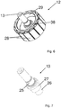
- Figure 6 shows a perspective view of the rotor 12 with the output shaft 13 and the carrier body 29, on which the permanent magnets 28 are applied on the outside.
- the carrier body 29 has an approximately H-shaped cross section in half-section, so that the bearing receiving sections with the bearing elements are arranged at least in sections within the permanent magnets 28 with respect to the permanent magnets 28 arranged on the outside of the carrier body 29.
- the hub of the carrier body 29 is provided with a radially circumferential projection 38 to increase the connection length, so that the projection 38 thus results in a deviation from the H-shape of the carrier body.
- the output shaft 13 has a first bearing section 25 and a second bearing section 26, on each of which a bearing element is received, with a rotor receiving section 27 being formed between the bearing sections 25, 26 on which the support body 29 equipped with the permanent magnets 28 is received with the projection 38.
Landscapes
- Engineering & Computer Science (AREA)
- Power Engineering (AREA)
- Physics & Mathematics (AREA)
- Thermal Sciences (AREA)
- Power-Operated Mechanisms For Wings (AREA)
Priority Applications (3)
| Application Number | Priority Date | Filing Date | Title |
|---|---|---|---|
| EP19214427.7A EP3835529B1 (fr) | 2019-12-09 | 2019-12-09 | Entraînement de porte doté d'une unité moteur, comportant un agencement palier avantageux permettant de loger un arbre de sortie |
| ES19214427T ES2978790T3 (es) | 2019-12-09 | 2019-12-09 | Accionamiento de puerta con unidad de motor, que presenta una disposición de cojinete ventajosa para soportar un árbol de salida de fuerza |
| PCT/EP2020/083648 WO2021115801A1 (fr) | 2019-12-09 | 2020-11-27 | Entraînement de porte comprenant une unité de moteur et un agencement de palier avantageux pour supporter un arbre de sortie |
Applications Claiming Priority (1)
| Application Number | Priority Date | Filing Date | Title |
|---|---|---|---|
| EP19214427.7A EP3835529B1 (fr) | 2019-12-09 | 2019-12-09 | Entraînement de porte doté d'une unité moteur, comportant un agencement palier avantageux permettant de loger un arbre de sortie |
Publications (3)
| Publication Number | Publication Date |
|---|---|
| EP3835529A1 true EP3835529A1 (fr) | 2021-06-16 |
| EP3835529B1 EP3835529B1 (fr) | 2024-03-13 |
| EP3835529C0 EP3835529C0 (fr) | 2024-03-13 |
Family
ID=68840903
Family Applications (1)
| Application Number | Title | Priority Date | Filing Date |
|---|---|---|---|
| EP19214427.7A Active EP3835529B1 (fr) | 2019-12-09 | 2019-12-09 | Entraînement de porte doté d'une unité moteur, comportant un agencement palier avantageux permettant de loger un arbre de sortie |
Country Status (3)
| Country | Link |
|---|---|
| EP (1) | EP3835529B1 (fr) |
| ES (1) | ES2978790T3 (fr) |
| WO (1) | WO2021115801A1 (fr) |
Citations (6)
| Publication number | Priority date | Publication date | Assignee | Title |
|---|---|---|---|---|
| DE10024021A1 (de) * | 1999-05-20 | 2001-01-04 | Hsu Chun Pu | Elektromotor/ Anti-vibration Electric Motor Having Well-ventilated Outer Rotor for Efficient Heat Dissipation |
| US20050274078A1 (en) * | 2004-06-14 | 2005-12-15 | Gilchrist Jimmy D | Automatic door control apparatus |
| DE102008046062A1 (de) | 2008-09-08 | 2010-03-11 | Dorma Gmbh + Co. Kg | Nachrüstsatz mit einer Antriebseinheit, insbesondere für eine automatische Schiebetür |
| EP2757219A2 (fr) * | 2013-01-21 | 2014-07-23 | Gebr. Willach GmbH | Dispositif d'entraînement de porte coulissante |
| US8823232B2 (en) * | 2010-06-11 | 2014-09-02 | Nidec Servo Corporation | Rotary electric machine |
| DE102014115932A1 (de) | 2014-10-31 | 2016-05-04 | Dorma Deutschland Gmbh | Türantrieb |
Family Cites Families (13)
| Publication number | Priority date | Publication date | Assignee | Title |
|---|---|---|---|---|
| US5497040A (en) | 1993-11-30 | 1996-03-05 | Sanyo Electric Co., Ltd. | Outer rotor type brusless DC motor |
| JP3039977U (ja) | 1997-01-10 | 1997-08-05 | 大健機電股▲分▼有限公司 | 自動扉の動力装置 |
| JP2007195344A (ja) | 2006-01-19 | 2007-08-02 | Jtekt Corp | モータ |
| CN201113612Y (zh) | 2007-07-31 | 2008-09-10 | 中山大洋电机股份有限公司 | 一种电机的外壳结构 |
| JP5206094B2 (ja) | 2008-04-25 | 2013-06-12 | 富士電機株式会社 | 移動体駆動装置 |
| JP2012095476A (ja) | 2010-10-28 | 2012-05-17 | Hitachi Car Eng Co Ltd | ブラシレスモータ |
| CN103078435B (zh) | 2012-12-25 | 2016-02-10 | 湖州太平微特电机有限公司 | 适用于电梯门机的超薄伺服电机 |
| CN204349752U (zh) | 2015-02-04 | 2015-05-20 | 佛山普瑞尔永磁电机科技有限公司 | 一种高效超短永磁同步门电机 |
| CN205829430U (zh) | 2016-07-05 | 2016-12-21 | 浙江优盛康科技有限公司 | 一种电梯开门机用防水永磁同步电动机 |
| CN107707055A (zh) | 2017-10-25 | 2018-02-16 | 珠海格力节能环保制冷技术研究中心有限公司 | 一种塑封电机 |
| US11139722B2 (en) * | 2018-03-02 | 2021-10-05 | Black & Decker Inc. | Motor having an external heat sink for a power tool |
| CN208433824U (zh) | 2018-08-15 | 2019-01-25 | 上海贝思特门机有限公司 | 电梯门机用永磁交流伺服电机 |
| CN109728675A (zh) | 2019-01-04 | 2019-05-07 | 杭州摩恩电机有限公司 | 外转子电梯门电机及其工作方法 |
-
2019
- 2019-12-09 ES ES19214427T patent/ES2978790T3/es active Active
- 2019-12-09 EP EP19214427.7A patent/EP3835529B1/fr active Active
-
2020
- 2020-11-27 WO PCT/EP2020/083648 patent/WO2021115801A1/fr not_active Ceased
Patent Citations (6)
| Publication number | Priority date | Publication date | Assignee | Title |
|---|---|---|---|---|
| DE10024021A1 (de) * | 1999-05-20 | 2001-01-04 | Hsu Chun Pu | Elektromotor/ Anti-vibration Electric Motor Having Well-ventilated Outer Rotor for Efficient Heat Dissipation |
| US20050274078A1 (en) * | 2004-06-14 | 2005-12-15 | Gilchrist Jimmy D | Automatic door control apparatus |
| DE102008046062A1 (de) | 2008-09-08 | 2010-03-11 | Dorma Gmbh + Co. Kg | Nachrüstsatz mit einer Antriebseinheit, insbesondere für eine automatische Schiebetür |
| US8823232B2 (en) * | 2010-06-11 | 2014-09-02 | Nidec Servo Corporation | Rotary electric machine |
| EP2757219A2 (fr) * | 2013-01-21 | 2014-07-23 | Gebr. Willach GmbH | Dispositif d'entraînement de porte coulissante |
| DE102014115932A1 (de) | 2014-10-31 | 2016-05-04 | Dorma Deutschland Gmbh | Türantrieb |
Also Published As
| Publication number | Publication date |
|---|---|
| ES2978790T3 (es) | 2024-09-20 |
| EP3835529B1 (fr) | 2024-03-13 |
| EP3835529C0 (fr) | 2024-03-13 |
| WO2021115801A1 (fr) | 2021-06-17 |
Similar Documents
| Publication | Publication Date | Title |
|---|---|---|
| DE102005018956A1 (de) | Vorrichtung zur Nockenwellenverstellung einer Brennkraftmaschine | |
| DE102008054842A1 (de) | Mischer | |
| EP0170989A1 (fr) | Dispositif de transmission à roue et vis sans fin | |
| EP2726756B1 (fr) | Entraînement de réglage pour un véhicule, notamment entraînement de hayon | |
| EP4217568B1 (fr) | Dispositif d'entraînement destiné à déplacer un battant | |
| EP3823893A1 (fr) | Transmission de bateau et système d'entraînement pour une propulsion de bateau | |
| EP1826359B1 (fr) | Barrière d'accès | |
| EP1573226B1 (fr) | Engrenage planetaire et moyens pour monter ledit engrenage planetaire sur un support de transmission | |
| EP3835529B1 (fr) | Entraînement de porte doté d'une unité moteur, comportant un agencement palier avantageux permettant de loger un arbre de sortie | |
| EP3835531B1 (fr) | Entrainement de porte doté d'une unité moteur d'encombrement réduit haute performance | |
| EP3835528B1 (fr) | Ensemble de porte doté d'une unité moteur, présentant une forme basique avantageuse | |
| EP3835534B1 (fr) | Entrainement de porte doté d'une unité moteur | |
| EP3513100B1 (fr) | Motoréducteur angulaire | |
| EP3835532B1 (fr) | Entrainement de porte doté d'une unité moteur d'une construction simple à densité d'intégration élevée | |
| EP3835533B1 (fr) | Entrainement de porte doté d'une unité moteur à faible encombrement | |
| WO2022063958A1 (fr) | Dispositif d'entraînement pour faire pivoter un battant, système de battant pivotant et utilisation du dispositif d'entraînement pour un entraînement de battant pivotant | |
| DE19718032A1 (de) | Maschine zum Stanzen, Biegen und Montieren von Blechteilen | |
| EP1563587A1 (fr) | Dispositif d'entrainement pour dispositifs de reglage de vehicules automobiles | |
| DE102014010275A1 (de) | Antriebsvorrichtung | |
| DE102023208572B3 (de) | Türantrieb und Türsystem | |
| EP3835530B1 (fr) | Entrainement de porte doté d'une unité de moteur, comportant une connection électrique avantageux | |
| DE1139196B (de) | Gehaeuseloser Elektromotor mit an den Stirnseiten des Statorblechpaketes befestigten Lagerschilden | |
| EP0260432A2 (fr) | Dispositif d'entraînement d'un refroidisseur à grille mobile | |
| EP0702447A2 (fr) | Moteur électrique sans boîtier avec flasques-palier | |
| DE1556323A1 (de) | Aufzugmaschine |
Legal Events
| Date | Code | Title | Description |
|---|---|---|---|
| PUAI | Public reference made under article 153(3) epc to a published international application that has entered the european phase |
Free format text: ORIGINAL CODE: 0009012 |
|
| STAA | Information on the status of an ep patent application or granted ep patent |
Free format text: STATUS: THE APPLICATION HAS BEEN PUBLISHED |
|
| AK | Designated contracting states |
Kind code of ref document: A1 Designated state(s): AL AT BE BG CH CY CZ DE DK EE ES FI FR GB GR HR HU IE IS IT LI LT LU LV MC MK MT NL NO PL PT RO RS SE SI SK SM TR |
|
| STAA | Information on the status of an ep patent application or granted ep patent |
Free format text: STATUS: REQUEST FOR EXAMINATION WAS MADE |
|
| 17P | Request for examination filed |
Effective date: 20211215 |
|
| RBV | Designated contracting states (corrected) |
Designated state(s): AL AT BE BG CH CY CZ DE DK EE ES FI FR GB GR HR HU IE IS IT LI LT LU LV MC MK MT NL NO PL PT RO RS SE SI SK SM TR |
|
| STAA | Information on the status of an ep patent application or granted ep patent |
Free format text: STATUS: EXAMINATION IS IN PROGRESS |
|
| 17Q | First examination report despatched |
Effective date: 20220419 |
|
| GRAP | Despatch of communication of intention to grant a patent |
Free format text: ORIGINAL CODE: EPIDOSNIGR1 |
|
| STAA | Information on the status of an ep patent application or granted ep patent |
Free format text: STATUS: GRANT OF PATENT IS INTENDED |
|
| RIC1 | Information provided on ipc code assigned before grant |
Ipc: H02K 9/22 20060101ALI20230915BHEP Ipc: H02K 7/116 20060101ALI20230915BHEP Ipc: H02K 5/16 20060101ALI20230915BHEP Ipc: H02K 5/04 20060101ALI20230915BHEP Ipc: E05F 15/643 20150101ALI20230915BHEP Ipc: E05F 15/603 20150101AFI20230915BHEP |
|
| INTG | Intention to grant announced |
Effective date: 20231011 |
|
| GRAS | Grant fee paid |
Free format text: ORIGINAL CODE: EPIDOSNIGR3 |
|
| GRAA | (expected) grant |
Free format text: ORIGINAL CODE: 0009210 |
|
| STAA | Information on the status of an ep patent application or granted ep patent |
Free format text: STATUS: THE PATENT HAS BEEN GRANTED |
|
| AK | Designated contracting states |
Kind code of ref document: B1 Designated state(s): AL AT BE BG CH CY CZ DE DK EE ES FI FR GB GR HR HU IE IS IT LI LT LU LV MC MK MT NL NO PL PT RO RS SE SI SK SM TR |
|
| REG | Reference to a national code |
Ref country code: GB Ref legal event code: FG4D Free format text: NOT ENGLISH |
|
| REG | Reference to a national code |
Ref country code: CH Ref legal event code: EP |
|
| REG | Reference to a national code |
Ref country code: DE Ref legal event code: R096 Ref document number: 502019010776 Country of ref document: DE |
|
| REG | Reference to a national code |
Ref country code: IE Ref legal event code: FG4D Free format text: LANGUAGE OF EP DOCUMENT: GERMAN |
|
| U01 | Request for unitary effect filed |
Effective date: 20240410 |
|
| U07 | Unitary effect registered |
Designated state(s): AT BE BG DE DK EE FI FR IT LT LU LV MT NL PT SE SI Effective date: 20240415 |
|
| PG25 | Lapsed in a contracting state [announced via postgrant information from national office to epo] |
Ref country code: GR Free format text: LAPSE BECAUSE OF FAILURE TO SUBMIT A TRANSLATION OF THE DESCRIPTION OR TO PAY THE FEE WITHIN THE PRESCRIBED TIME-LIMIT Effective date: 20240614 |
|
| PG25 | Lapsed in a contracting state [announced via postgrant information from national office to epo] |
Ref country code: RS Free format text: LAPSE BECAUSE OF FAILURE TO SUBMIT A TRANSLATION OF THE DESCRIPTION OR TO PAY THE FEE WITHIN THE PRESCRIBED TIME-LIMIT Effective date: 20240613 Ref country code: HR Free format text: LAPSE BECAUSE OF FAILURE TO SUBMIT A TRANSLATION OF THE DESCRIPTION OR TO PAY THE FEE WITHIN THE PRESCRIBED TIME-LIMIT Effective date: 20240313 |
|
| PG25 | Lapsed in a contracting state [announced via postgrant information from national office to epo] |
Ref country code: RS Free format text: LAPSE BECAUSE OF FAILURE TO SUBMIT A TRANSLATION OF THE DESCRIPTION OR TO PAY THE FEE WITHIN THE PRESCRIBED TIME-LIMIT Effective date: 20240613 Ref country code: NO Free format text: LAPSE BECAUSE OF FAILURE TO SUBMIT A TRANSLATION OF THE DESCRIPTION OR TO PAY THE FEE WITHIN THE PRESCRIBED TIME-LIMIT Effective date: 20240613 Ref country code: HR Free format text: LAPSE BECAUSE OF FAILURE TO SUBMIT A TRANSLATION OF THE DESCRIPTION OR TO PAY THE FEE WITHIN THE PRESCRIBED TIME-LIMIT Effective date: 20240313 Ref country code: GR Free format text: LAPSE BECAUSE OF FAILURE TO SUBMIT A TRANSLATION OF THE DESCRIPTION OR TO PAY THE FEE WITHIN THE PRESCRIBED TIME-LIMIT Effective date: 20240614 |
|
| REG | Reference to a national code |
Ref country code: ES Ref legal event code: FG2A Ref document number: 2978790 Country of ref document: ES Kind code of ref document: T3 Effective date: 20240920 |
|
| PG25 | Lapsed in a contracting state [announced via postgrant information from national office to epo] |
Ref country code: IS Free format text: LAPSE BECAUSE OF FAILURE TO SUBMIT A TRANSLATION OF THE DESCRIPTION OR TO PAY THE FEE WITHIN THE PRESCRIBED TIME-LIMIT Effective date: 20240713 |
|
| PG25 | Lapsed in a contracting state [announced via postgrant information from national office to epo] |
Ref country code: SM Free format text: LAPSE BECAUSE OF FAILURE TO SUBMIT A TRANSLATION OF THE DESCRIPTION OR TO PAY THE FEE WITHIN THE PRESCRIBED TIME-LIMIT Effective date: 20240313 |
|
| PG25 | Lapsed in a contracting state [announced via postgrant information from national office to epo] |
Ref country code: CZ Free format text: LAPSE BECAUSE OF FAILURE TO SUBMIT A TRANSLATION OF THE DESCRIPTION OR TO PAY THE FEE WITHIN THE PRESCRIBED TIME-LIMIT Effective date: 20240313 |
|
| PG25 | Lapsed in a contracting state [announced via postgrant information from national office to epo] |
Ref country code: PL Free format text: LAPSE BECAUSE OF FAILURE TO SUBMIT A TRANSLATION OF THE DESCRIPTION OR TO PAY THE FEE WITHIN THE PRESCRIBED TIME-LIMIT Effective date: 20240313 |
|
| PG25 | Lapsed in a contracting state [announced via postgrant information from national office to epo] |
Ref country code: SK Free format text: LAPSE BECAUSE OF FAILURE TO SUBMIT A TRANSLATION OF THE DESCRIPTION OR TO PAY THE FEE WITHIN THE PRESCRIBED TIME-LIMIT Effective date: 20240313 |
|
| PG25 | Lapsed in a contracting state [announced via postgrant information from national office to epo] |
Ref country code: SM Free format text: LAPSE BECAUSE OF FAILURE TO SUBMIT A TRANSLATION OF THE DESCRIPTION OR TO PAY THE FEE WITHIN THE PRESCRIBED TIME-LIMIT Effective date: 20240313 Ref country code: SK Free format text: LAPSE BECAUSE OF FAILURE TO SUBMIT A TRANSLATION OF THE DESCRIPTION OR TO PAY THE FEE WITHIN THE PRESCRIBED TIME-LIMIT Effective date: 20240313 Ref country code: RO Free format text: LAPSE BECAUSE OF FAILURE TO SUBMIT A TRANSLATION OF THE DESCRIPTION OR TO PAY THE FEE WITHIN THE PRESCRIBED TIME-LIMIT Effective date: 20240313 Ref country code: PL Free format text: LAPSE BECAUSE OF FAILURE TO SUBMIT A TRANSLATION OF THE DESCRIPTION OR TO PAY THE FEE WITHIN THE PRESCRIBED TIME-LIMIT Effective date: 20240313 Ref country code: IS Free format text: LAPSE BECAUSE OF FAILURE TO SUBMIT A TRANSLATION OF THE DESCRIPTION OR TO PAY THE FEE WITHIN THE PRESCRIBED TIME-LIMIT Effective date: 20240713 Ref country code: CZ Free format text: LAPSE BECAUSE OF FAILURE TO SUBMIT A TRANSLATION OF THE DESCRIPTION OR TO PAY THE FEE WITHIN THE PRESCRIBED TIME-LIMIT Effective date: 20240313 |
|
| REG | Reference to a national code |
Ref country code: DE Ref legal event code: R026 Ref document number: 502019010776 Country of ref document: DE |
|
| PLBI | Opposition filed |
Free format text: ORIGINAL CODE: 0009260 |
|
| PLAX | Notice of opposition and request to file observation + time limit sent |
Free format text: ORIGINAL CODE: EPIDOSNOBS2 |
|
| 26 | Opposition filed |
Opponent name: GILGEN DOOR SYSTEMS AG Effective date: 20241212 |
|
| U20 | Renewal fee for the european patent with unitary effect paid |
Year of fee payment: 6 Effective date: 20241227 |
|
| PLBB | Reply of patent proprietor to notice(s) of opposition received |
Free format text: ORIGINAL CODE: EPIDOSNOBS3 |
|
| PG25 | Lapsed in a contracting state [announced via postgrant information from national office to epo] |
Ref country code: MC Free format text: LAPSE BECAUSE OF FAILURE TO SUBMIT A TRANSLATION OF THE DESCRIPTION OR TO PAY THE FEE WITHIN THE PRESCRIBED TIME-LIMIT Effective date: 20240313 |
|
| PG25 | Lapsed in a contracting state [announced via postgrant information from national office to epo] |
Ref country code: IE Free format text: LAPSE BECAUSE OF NON-PAYMENT OF DUE FEES Effective date: 20241209 |
|
| REG | Reference to a national code |
Ref country code: CH Ref legal event code: U11 Free format text: ST27 STATUS EVENT CODE: U-0-0-U10-U11 (AS PROVIDED BY THE NATIONAL OFFICE) Effective date: 20260101 |
|
| PGFP | Annual fee paid to national office [announced via postgrant information from national office to epo] |
Ref country code: GB Payment date: 20251219 Year of fee payment: 7 |
|
| U20 | Renewal fee for the european patent with unitary effect paid |
Year of fee payment: 7 Effective date: 20251230 |
|
| PGFP | Annual fee paid to national office [announced via postgrant information from national office to epo] |
Ref country code: ES Payment date: 20260130 Year of fee payment: 7 |
|
| PGFP | Annual fee paid to national office [announced via postgrant information from national office to epo] |
Ref country code: CH Payment date: 20260101 Year of fee payment: 7 |