EP3927520B1 - Verfahren und vorrichtung zum anheften der ränder einer extrudierten masse - Google Patents
Verfahren und vorrichtung zum anheften der ränder einer extrudierten masse Download PDFInfo
- Publication number
- EP3927520B1 EP3927520B1 EP20706593.9A EP20706593A EP3927520B1 EP 3927520 B1 EP3927520 B1 EP 3927520B1 EP 20706593 A EP20706593 A EP 20706593A EP 3927520 B1 EP3927520 B1 EP 3927520B1
- Authority
- EP
- European Patent Office
- Prior art keywords
- support
- edge
- respect
- nozzle
- width
- Prior art date
- Legal status (The legal status is an assumption and is not a legal conclusion. Google has not performed a legal analysis and makes no representation as to the accuracy of the status listed.)
- Active
Links
Images



Classifications
-
- B—PERFORMING OPERATIONS; TRANSPORTING
- B29—WORKING OF PLASTICS; WORKING OF SUBSTANCES IN A PLASTIC STATE IN GENERAL
- B29C—SHAPING OR JOINING OF PLASTICS; SHAPING OF MATERIAL IN A PLASTIC STATE, NOT OTHERWISE PROVIDED FOR; AFTER-TREATMENT OF THE SHAPED PRODUCTS, e.g. REPAIRING
- B29C48/00—Extrusion moulding, i.e. expressing the moulding material through a die or nozzle which imparts the desired form; Apparatus therefor
- B29C48/03—Extrusion moulding, i.e. expressing the moulding material through a die or nozzle which imparts the desired form; Apparatus therefor characterised by the shape of the extruded material at extrusion
- B29C48/07—Flat, e.g. panels
- B29C48/08—Flat, e.g. panels flexible, e.g. films
-
- B—PERFORMING OPERATIONS; TRANSPORTING
- B29—WORKING OF PLASTICS; WORKING OF SUBSTANCES IN A PLASTIC STATE IN GENERAL
- B29C—SHAPING OR JOINING OF PLASTICS; SHAPING OF MATERIAL IN A PLASTIC STATE, NOT OTHERWISE PROVIDED FOR; AFTER-TREATMENT OF THE SHAPED PRODUCTS, e.g. REPAIRING
- B29C48/00—Extrusion moulding, i.e. expressing the moulding material through a die or nozzle which imparts the desired form; Apparatus therefor
- B29C48/25—Component parts, details or accessories; Auxiliary operations
- B29C48/30—Extrusion nozzles or dies
- B29C48/305—Extrusion nozzles or dies having a wide opening, e.g. for forming sheets
-
- B—PERFORMING OPERATIONS; TRANSPORTING
- B29—WORKING OF PLASTICS; WORKING OF SUBSTANCES IN A PLASTIC STATE IN GENERAL
- B29C—SHAPING OR JOINING OF PLASTICS; SHAPING OF MATERIAL IN A PLASTIC STATE, NOT OTHERWISE PROVIDED FOR; AFTER-TREATMENT OF THE SHAPED PRODUCTS, e.g. REPAIRING
- B29C48/00—Extrusion moulding, i.e. expressing the moulding material through a die or nozzle which imparts the desired form; Apparatus therefor
- B29C48/25—Component parts, details or accessories; Auxiliary operations
- B29C48/88—Thermal treatment of the stream of extruded material, e.g. cooling
- B29C48/911—Cooling
- B29C48/9135—Cooling of flat articles, e.g. using specially adapted supporting means
- B29C48/914—Cooling drums
-
- B—PERFORMING OPERATIONS; TRANSPORTING
- B29—WORKING OF PLASTICS; WORKING OF SUBSTANCES IN A PLASTIC STATE IN GENERAL
- B29C—SHAPING OR JOINING OF PLASTICS; SHAPING OF MATERIAL IN A PLASTIC STATE, NOT OTHERWISE PROVIDED FOR; AFTER-TREATMENT OF THE SHAPED PRODUCTS, e.g. REPAIRING
- B29C48/00—Extrusion moulding, i.e. expressing the moulding material through a die or nozzle which imparts the desired form; Apparatus therefor
- B29C48/25—Component parts, details or accessories; Auxiliary operations
- B29C48/88—Thermal treatment of the stream of extruded material, e.g. cooling
- B29C48/911—Cooling
- B29C48/9135—Cooling of flat articles, e.g. using specially adapted supporting means
- B29C48/915—Cooling of flat articles, e.g. using specially adapted supporting means with means for improving the adhesion to the supporting means
- B29C48/9165—Electrostatic pinning
-
- B—PERFORMING OPERATIONS; TRANSPORTING
- B29—WORKING OF PLASTICS; WORKING OF SUBSTANCES IN A PLASTIC STATE IN GENERAL
- B29C—SHAPING OR JOINING OF PLASTICS; SHAPING OF MATERIAL IN A PLASTIC STATE, NOT OTHERWISE PROVIDED FOR; AFTER-TREATMENT OF THE SHAPED PRODUCTS, e.g. REPAIRING
- B29C48/00—Extrusion moulding, i.e. expressing the moulding material through a die or nozzle which imparts the desired form; Apparatus therefor
- B29C48/25—Component parts, details or accessories; Auxiliary operations
- B29C48/88—Thermal treatment of the stream of extruded material, e.g. cooling
- B29C48/911—Cooling
- B29C48/9135—Cooling of flat articles, e.g. using specially adapted supporting means
- B29C48/915—Cooling of flat articles, e.g. using specially adapted supporting means with means for improving the adhesion to the supporting means
- B29C48/917—Cooling of flat articles, e.g. using specially adapted supporting means with means for improving the adhesion to the supporting means by applying pressurised gas to the surface of the flat article
Definitions
- the present invention relates to an edge-pinning group in a plastic film extrusion machine and method for pinning the edges of an extruded mass.
- plastic film for flexible packaging (commonly known as “film") can be carried out using various technologies, among which the most important and the most widespread are certainly the so-called “blown technology” and the so-called “cast” technology.
- the plastic resin is extruded from the bottom upwards by means of a circular die, and is simultaneously cooled by a blowing of air which envelops it circumferentially.
- the cooling process in addition obviously to the intrinsic quality of the raw materials used, represents the most important production parameter of the whole production process, the parameter that most influences the quality of the final product.
- this apparatus essentially looks like a heat exchanger, with a hot fluid (i.e. the melt) and a cold fluid (i.e. the refrigerant, of any type) separated by a Fourier wall (i.e. the rotating cylinder).
- the width of the melt 10 gradually decreases, "sliding" on the surface of the cylinder, due to the molecular bonds present inside it, which tend to lose energy, by agglomerating, as already mentioned, in the most favourable energy condition possible, that is, that with the least potential.
- edge-pinning device that is a device capable of generating an extremely high-voltage electric discharge (up to 30 kV and more), but with a very low amperage (at the most a few tenths of a mA); this discharge directly affects the extreme edges of the melt 10 when it touches the rotating cylinder 11 and consequently, as the cylinder 11, typically metallic, is rotating, the adhesion is obtained between the two elements.
- edge-pinning systems 13 can also be seen, schematically represented as "cubes" from which some electrodes emerge (variable in number), which provide for the generation of the electrical discharge previously described.
- edge-pinning system which can have the most varied embodiments (cylinder, strip, cube, single electrode rather than multiple electrodes) is therefore still used today in all plastic film production plants produced with the cast technology.
- This film which represents the sector of greatest world consumption of polyethylene, in turn the most widespread thermoplastic resin on a worldwide level, in the past had a commonly used reference thickness, i.e. 23 microns; by choosing different types of resins, more or less valuable, the physical and mechanical characteristics of the film could be varied considerably, but the thickness was considered practically a constant.
- edge-pinning devices has the specific purpose of making the edges of the melt adhere to the chill-roll so as to avoid, or at least minimize, the neck-in phenomenon, in turn deriving from the tendency of the melt to "pursue" its condition with less potential; this trend, however, does not only concern the edges of the melt, but the whole body of the melt which therefore tends to move towards the centre of the chill-roll, literally “sliding" over it.
- low-thickness area 16 is substantially irrelevant in the case of the production of high-thickness films (as it is in any case part of the area of film which is trimmed before winding), it becomes of particular importance however when considering low-thickness films.
- the reduced thickness area 16 can have values equal to a few microns; it is evident that under these conditions, the stability of this area of the film is extremely labile, as an impurity, albeit microscopic, is sufficient for creating a hole or, even worse, the complete breakage of the film.
- the high extrusion rate determines, as already mentioned above, a considerable temperature of the melt at the moment of its contact with the chill-roll, or at the moment of the action of the electrostatic discharge generated by the edge-pinning system; this significant temperature can lead to various negative effects, first of all a definite instability of the melt which, as it is in a semi-liquid state, does not have its own shape and is therefore difficult to control.
- edge-pinning device has the purpose of charging the edge of the melt with electrostatic current to facilitate its adhesion with the chill-roll; the very nature of the polymers, which are extremely poor current conductors (they are in fact excellent insulators), causes this charge to be concentrated particularly in correspondence with the electrodes of the same edge-pinning device, and not on a larger area.
- edge-pinning devices The circumscription of the area affected by the edge-pinning devices is well seen also from a production point of view, as the smaller this area, the greater will be the portion of film not "disturbed" by the neck-in action and of the edge-pinning device itself; it is therefore common practice to reduce the area of action of the edge-pinning device to the minimum, limiting it to the most extreme edge (10-20 mm maximum) of the melt.
- edge-pinning devices An excessively “extreme” positioning of the edge-pinning devices, or too much on the edge, could therefore cause the loss of the same due to said slight oscillations in the width of the melt; it is therefore customary for said edge-pinning devices to be positioned a few mm with respect to the edge, in order to remedy these variations.
- the classic positioning of the edge-pinning device 13 can be appreciated, i.e. at a height of 15' with respect to the extreme edge of the melt 10 (said edge, as already mentioned, being variable to the extent of a few mm) .
- the height 15' represents the variation in width to which the melt is subject due to the inevitable tolerances to which the raw material itself is subject, and therefore cannot be controlled a priori.
- edge-pinning groups according to the state of the art, not without the drawbacks specified above, are described in US 2013/320596 , US 2012/086155 , US 3,779,682 and US 4,255,365 .
- the present invention therefore intends to brilliantly overcome all the limits described above by means of a particular edge-pinning group, consisting of various elements already known in the common art, but combined in an absolutely innovative way.
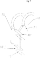
- the present invention therefore relates to an edge-pinning group 13 in a plastic film extrusion machine, comprising or consisting of the following elements: a pair of supports 18', 18", each support 18', 18" bearing at least one electrode 19, and a pair of nozzles 20, 21, said group being characterized in that said elements are positioned in the edge-pinning group 13 with respect to the extrusion direction of the machine "Y” and with respect to the extrusion surface (S), passing through or containing the extrusion direction of the machine "Y”, as follows:
- Said nozzles 20, 21 are configured for being supplied with compressed air or with air coming from an independent blower.
- the second support 18" is positioned externally with respect to the first support 18' and can be in line with the support 18'.
- the present invention also relates to a method for pinning the edges of an extruded polymeric mass 10, comprising the following steps:
- the area having a width (a) 15' has a variable width as it includes the tip, which is variable, of the edges of the extruded mass 10.
- the second support 18 positioned externally with respect to the second nozzle 20 and the first support 18', in turn arranged in parallel, is positioned in correspondence with the area having a width (a) 15'.
- the value of the width (a) 15' is substantially variable within a range of 0 to 10 mm approximately
- the value of the width (b) 15 is substantially included within a range of 15 to 25 mm approximately.
- the value of the width (c) 16 is substantially variable within a range of 20 mm to 50 mm approximately.
- the present invention also relates to a machine for the extrusion of plastic film comprising said edge-pinning group.
- Said machine for the extrusion of plastic film 10 comprises an extrusion die 12, a rotating cylinder or chill-roll 11 and at least one edge-pinning group 13, wherein said edge-pinning group 13 comprises or consists of the following elements: a pair of supports 18', 18", each support 18', 18" bearing at least one electrode 19, and a pair of nozzles 20, 21, said elements of the edge-pinning group 13 being positioned in said group 13, in said machine, as follows with respect to the extrusion direction of the machine "Y" and with respect to the surface (R) of the cooling cylinder 11:
- Said edge-pinning group 13 in a machine for the extrusion of plastic film 10 can also be defined as an edge-pinning group 13 comprising or consisting of the following elements: a pair of supports 18', 18", each support 18', 18" bearing at least one electrode 19, and a pair of nozzles 20, 21, said group being characterized in that said elements are positioned in the edge-pinning group with respect to the extrusion direction of the machine "Y", as follows:
- figure 7 schematically shows the edge-pinning group 13 object of the present invention, consisting of a pair of supports 18' and 18", each support 18' and 18" bearing at least one electrode 19, and a pair of nozzles 20 and 21, each of which is supplied with compressed air or with air from an independent blower.
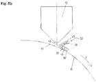
- Figure 8a shows in particular the spatial interaction between the various elements with reference to the centre line of the extrusion surface (S), passing through or containing the extrusion direction of the machine "Y" and with respect to the axis Y which obviously corresponds to the axis of the extrusion line.
- the first element present is the nozzle 21, which partially pre-cools the area of extruded melt 10 which, with reference to the centre line of the extrusion surface (S), corresponds to the area 16 indicated in figure 4 , said area having a width (c) .
- This area of the melt in the absence of this pre-cooling, would tend to "slide" towards the centre of the chill-roll, generating the above-mentioned area 16 having a reduced thickness; through the action of the nozzle 21, on the other hand, the formation of this area 16 having a reduced thickness can be completely avoided, decreasing its potential by removing heat, thus prefiguring the formation of a film with a constant thickness (except of course for the area 15 affected by the neck-in).
- this nozzle 21 appears even clearer by looking at figure 8b , where it can be seen that the action of the air blow ensured by this nozzle 21 envelops the area 16 of the melt 10 before it even touches the surface (R) of the chill-roll 11 and is therefore subjected to the cooling process which relates to the whole film, and which therefore cannot be controlled sectorally.
- the second element present in spatial order, again following the axis "Y", is the nozzle 20, whose action allows the partial pre-cooling of the edge area of the melt 10 (said area having a width (b) 15 of the same) affected by the electrostatic discharge of the electrodes before it comes into contact with the chill-roll, allowing better control even in the case of high velocities and reduced thicknesses and thus avoiding said draw-down-resonance phenomena.
- Figure 8b shows how the action of this nozzle 20 takes place preferably (but not exclusively) on the melt 10, immediately before it comes into contact with the surface of the chill-roll 11, for the same reasons explained in the previous paragraph.
- the support 18' bearing at least one electrode 19, which, as already indicated, is perfectly aligned with the nozzle 20; its positioning with respect to the centre line of the extrusion surface (S) is therefore also identified by the area having a width (b) 15, previously mentioned.
- this support is, as already mentioned, that of classic edge-pinning devices, i.e. it must electrostatically charge a portion of the melt as small as possible in order to favour its adhesion to the surface of the chill-roll and consequently ensure the correct heat exchange between the two elements. This portion corresponds to the area having a width (b), 15, previously defined.
- the support 18 which is preferably, but not exclusively, positioned further downstream with respect to the support 18" in the extrusion direction "Y", but above all it is displaced with respect to the centre line of the extrusion surface (S), in the area having a width (a) 15' towards the variable edge of the melt 10.
- the extent of the width of the area (a) 15' is subject to even major and significant variations based on the type of polymer and the process conditions.
- this support 18 also equipped with at least one electrode 19, is essentially that of blocking the variable portion of melt corresponding to the area having a width (a) 15', which is thus caused to adhere to the chill-roll, avoiding the formation of the peduncle shown in figure 6 , but which, even in its absence, (due as said to the variability of the width of the melt), in no way jeopardizes the stability of the film thanks to the action of the first support 18'.
- the essential elements are obviously all the elements forming the edge-pinning system according to the present invention and the interaction between the same, fundamental for ensuring the correct functioning of the invention.
Landscapes
- Engineering & Computer Science (AREA)
- Mechanical Engineering (AREA)
- Physics & Mathematics (AREA)
- Thermal Sciences (AREA)
- Manufacturing & Machinery (AREA)
- Extrusion Moulding Of Plastics Or The Like (AREA)
Claims (8)
- Verfahren zum Anheften der Ränder einer extrudierten Polymermasse (10), das die folgenden Schritte umfasst:- einen Extrusionsschritt, bei dem die Polymermasse (10) aus einem Extrusionswerkzeug (12) extrudiert wird; mindestens zwei Vorkühlungsschritte, wobei- in der extrudierten Polymermasse (10) zwei Bereiche entlang jedem der Außenränder der Masse selbst definiert werden, die jeweils eine Breite gleich (a) und (b) (15' und 15) und eine Länge gleich der Länge der extrudierten Masse (10) aufweisen, wobei der Bereich mit einer Breite (a) (15'), der eine variable Breite aufweist, bündig mit dem Rand der extrudierten Masse (10) angeordnet ist und der Bereich mit einer Breite (b) (15) an den Bereich mit einer Breite (a) (15') angrenzt, und zwar innen von dem Rand der extrudierten Masse (10), und- einen dritten Bereich mit einer Breite gleich (c), (16) und einer Länge gleich der Länge der extrudierten Masse (10), angrenzend an den Bereich mit einer Breite (b) (15), und zwar innen in Bezug auf den Rand der extrudierten Masse (10);- in dem ersten Vorkühlungsschritt der Bereich (16) mit einer Breite (c) der Polymermasse (10) durch die Wirkung eines Luftstroms vorgekühlt wird, bevor die extrudierte Masse (10) gegossen wird und mit der Oberfläche eines rotierenden Zylinders (11) in Kontakt kommt, der in einem Abstand d von dem Extrusionswerkzeug (12) angeordnet ist;- in dem zweiten nachfolgenden Vorkühlungsschritt der Bereich (15) mit einer Breite (b) mittels eines zweiten Luftstroms vorgekühlt wird, bevor die extrudierte Masse (10) gegossen wird und mit der Oberfläche eines rotierenden Zylinders ( 11) in Kontakt kommt, der in einem Abstand d von dem Extrusionswerkzeug (12) angeordnet ist;wobei das Verfahren dadurch gekennzeichnet ist, dass es mindestens zwei Schritte einer elektrostatischen Aufladung der extrudierten Polymermasse (10) umfasst, wobei- in dem ersten Schritt der elektrostatischen Aufladung der Bereich mit einer Breite (b) (15), der im vorherigen Schritt vorgekühlt wurde, elektrostatisch aufgeladen wird, um seine Anhaftung an der Oberfläche des Zylinders (11) zu begünstigen und den richtigen Wärmeaustausch zwischen den beiden Elementen zu gewährleisten;- in dem zweiten Schritt der elektrostatischen Aufladung der Bereich mit einer Breite (a) (15'), der bündig mit den Rändern der extrudierten Masse (10) angeordnet ist, außen in Bezug auf den Bereich mit einer Breite (b) (15), der im vorherigen Schritt behandelt wurde, elektrostatisch aufgeladen wird.
- Verfahren nach Anspruch 1, wobei die extrudierte Polymermasse (10) eine Polyethylenfolie, vorzugsweise ein lineares Polyethylen niedriger Dichte, mit einer Dicke im Bereich von 6 Mikron bis 20 Mikron ist, die Extrusionsgeschwindigkeit von 500 m/min bis über 800 m/min reicht, der Wert der Breite (a) (15') in einem Bereich von etwa 0 bis 10 mm variabel ist, der Wert der Breite (b) (15) in einem Bereich von etwa 15 bis 25 mm liegt, und der Wert der Breite (c) (16) in einem Bereich von 20 bis 50 mm variabel ist.
- Randanheftungsgruppe (13) in einer Maschine für die Extrusion von Kunststofffolie, die die folgenden Elemente umfasst oder aus ihnen besteht: ein Paar Träger (18', 18"), wobei jeder Träger (18', 18") mindestens eine Elektrode (19) lagert, und ein Düsenpaar (20, 21), wobei die Gruppe dadurch gekennzeichnet ist, dass die Elemente in der Randanheftungsgruppe (13) in Bezug auf die Extrusionsrichtung der Maschine "Y" und in Bezug auf die Extrusionsfläche (S), die durch die Extrusionsrichtung der Maschine "Y" verläuft oder diese enthält, wie folgt angeordnet sind:- die erste Düse (21) ist in Bezug auf die Richtung "Y" stromaufwärts von der zweiten Düse (20) angeordnet, wobei die zweite Düse (20) stromaufwärts und in einer Linie mit dem ersten Träger (18') angeordnet ist und der zweite Träger (18") parallel zu oder stromabwärts von dem ersten Träger (18') angeordnet ist;- der zweite Träger (18") ist in Bezug auf die Mittellinie der Extrusionsfläche (S) außen von dem ersten Träger (18') angeordnet, wobei der erste Träger (18') parallel zu der zweiten Düse (20) angeordnet ist, die ihrerseits außen von der ersten Düse (21) angeordnet ist.
- Randanheftungsgruppe nach Anspruch 3, wobei die Düsen (20, 21) so konfiguriert sind, dass sie mit Druckluft oder mit Luft, die von einem unabhängigen Gebläse kommt, versorgt werden.
- Randanheftungsgruppe nach einem der vorhergehenden Ansprüche 3 oder 4, wobei der zweite Träger (18") in Bezug auf den ersten Träger (18') außen angeordnet ist und mit dem Träger (18') in Bezug auf die Mittellinie der Extrusionsfläche (S) in einer Linie liegt.
- Randanheftungsgruppe (13) in einer Maschine für die Extrusion von Kunststofffolie, die die folgenden Elemente umfasst oder aus ihnen besteht: ein Paar Träger (18', 18"), wobei jeder Träger (18', 18") mindestens eine Elektrode (19) lagert, und ein Paar Düsen (20, 21), wobei die Gruppe dadurch gekennzeichnet ist, dass die Elemente in der Randanheftungsgruppe in Bezug auf die Extrusionsrichtung der Maschine "Y" wie folgt angeordnet sind:- die erste Düse (21) ist in Bezug auf die Richtung "Y" stromaufwärts von der zweiten Düse (20) angeordnet, die zweite Düse (20) ist stromaufwärts und in einer Linie mit dem ersten Träger (18') angeordnet, und der zweite Träger (18") ist parallel zu oder stromabwärts von dem ersten Träger (18') angeordnet;wobei diese Elemente auch dadurch gekennzeichnet sind, dass- die erste Düse (21) so konfiguriert ist, dass sie einen Bereich (16) der extrudierten Schmelze (10) teilweise vorkühlt, bevor diese überhaupt die Oberfläche eines rotierenden Zylinders (11) berührt, um ihr Potenzial durch Wärmeabfuhr zu verringern;- die zweite Düse (20) so konfiguriert ist, dass sie einen Randbereich der Schmelze (10), der von der elektrostatischen Entladung der einen oder mehreren auf dem ersten Träger (18') angeordneten Elektroden (19) beeinflusst wird, vorkühlt, bevor sie mit dem rotierenden Zylinder (11) in Kontakt kommt;- der erste Träger (18') so konfiguriert ist, dass er den Randbereich (15) der durch die zweite Düse (20) gekühlten Schmelze (10) elektrostatisch auflädt, um deren Anhaftung an der Oberfläche des rotierenden Zylinders (11) zu erleichtern und folglich den richtigen Wärmeaustausch zwischen den beiden Elementen zu gewährleisten;- der zweite Träger (18") so konfiguriert ist, dass er den äußeren Randbereich (15') der Schmelze (10) blockiert, so dass diese an dem sich drehenden Zylinder (11) anhaftet und die Bildung von Schmelzstielen verhindert wird.
- Maschine für die Extrusion von Kunststofffolie mit mindestens einer Randanheftungsgruppe nach einem der Ansprüche 3 bis 6.
- Maschine für die Extrusion von Kunststofffolie (10), die ein Extrusionswerkzeug (12), einen rotierenden Zylinder oder eine Kühlwalze (11) und mindestens eine Randanheftungsgruppe (13) umfasst, wobei die Randanheftungsgruppe (13) die folgenden Elemente umfasst oder aus ihnen besteht: ein Paar Träger (18', 18"), wobei jeder Träger (18', 18") mindestens eine Elektrode (19) lagert, und ein Paar Düsen (20, 21), wobei die Randanheftungsgruppe (13) dadurch gekennzeichnet ist, dass die Elemente in der Randanheftungsgruppe (13) in Bezug auf die Extrusionsrichtung der Maschine "Y" und in Bezug auf die Oberfläche (R) des Kühlzylinders (11) wie folgt angeordnet sind:- die erste Düse (21) ist in Bezug auf die Richtung "Y" stromaufwärts von der zweiten Düse (20) angeordnet ist, wobei die zweite Düse (20) stromaufwärts von und in einer Linie mit dem ersten Träger (18') angeordnet ist, und der zweite Träger (18") parallel zu oder stromabwärts von dem ersten Träger (18') angeordnet ist;- der zweite Träger (18") ist in Bezug auf die Mittellinie der Oberfläche (R) des Kühlzylinders (11) außen in Bezug auf den ersten Träger (18') angeordnet, wobei der erste Träger (18') parallel zu der zweiten Düse (20) angeordnet ist, die ihrerseits außen von der ersten Düse (21) angeordnet ist.
Applications Claiming Priority (3)
| Application Number | Priority Date | Filing Date | Title |
|---|---|---|---|
| IT102019000002389A IT201900002389A1 (it) | 2019-02-19 | 2019-02-19 | Gruppo fissabordi in una macchina di estrusione di film plastico e metodo di fissaggio dei bordi di una massa estrusa |
| IT202000002317 | 2020-02-06 | ||
| PCT/IB2020/051123 WO2020170075A1 (en) | 2019-02-19 | 2020-02-12 | Method and apparatus for pinning the edges of an extruded mass |
Publications (2)
| Publication Number | Publication Date |
|---|---|
| EP3927520A1 EP3927520A1 (de) | 2021-12-29 |
| EP3927520B1 true EP3927520B1 (de) | 2022-09-28 |
Family
ID=69646023
Family Applications (1)
| Application Number | Title | Priority Date | Filing Date |
|---|---|---|---|
| EP20706593.9A Active EP3927520B1 (de) | 2019-02-19 | 2020-02-12 | Verfahren und vorrichtung zum anheften der ränder einer extrudierten masse |
Country Status (6)
| Country | Link |
|---|---|
| US (3) | US12011864B2 (de) |
| EP (1) | EP3927520B1 (de) |
| CN (1) | CN113396040A (de) |
| CA (1) | CA3125727A1 (de) |
| PL (1) | PL3927520T3 (de) |
| WO (1) | WO2020170075A1 (de) |
Family Cites Families (15)
| Publication number | Priority date | Publication date | Assignee | Title |
|---|---|---|---|---|
| US3779682A (en) * | 1972-03-08 | 1973-12-18 | Du Pont | Quenching molten thermoplastic film |
| US3795474A (en) * | 1972-03-08 | 1974-03-05 | Du Pont | Molten thermoplastic web quenching apparatus |
| US4255365A (en) * | 1979-01-23 | 1981-03-10 | E. I. Du Pont De Nemours And Company | Pneumatic gauge adjustment of edge-pinned cast web |
| US4272312A (en) * | 1979-11-01 | 1981-06-09 | Champion International Corporation | Process for extruding films of thermoplastic polyester film-forming materials |
| JPS6015118A (ja) * | 1983-06-28 | 1985-01-25 | ユニオン・カ−バイド・コ−ポレ−シヨン | Lldpe樹脂からフイルムを形成する際のエツジウエバ−の減少方法 |
| US4676851A (en) * | 1984-04-25 | 1987-06-30 | First Brands Corporation | Process and apparatus for forming integral interlocking closure film stock |
| JPS62255113A (ja) * | 1986-04-28 | 1987-11-06 | Diafoil Co Ltd | 液晶ポリマ−の製膜方法 |
| JPS6395930A (ja) * | 1986-10-14 | 1988-04-26 | Idemitsu Petrochem Co Ltd | 液晶性ポリエステルフイルムの製造方法 |
| JP3358881B2 (ja) * | 1994-07-29 | 2002-12-24 | 三菱重工業株式会社 | 熱可塑性合成樹脂薄膜の製造装置 |
| JPH10315306A (ja) * | 1997-05-19 | 1998-12-02 | Toray Ind Inc | 静電印加キャスト装置 |
| AT503110B1 (de) * | 2006-04-19 | 2007-08-15 | Sml Maschinengesellschaft Mbh | Vorrichtung zum kühlen eines kunststoffschmelzfilms |
| JP5686537B2 (ja) * | 2010-06-30 | 2015-03-18 | 東洋鋼鈑株式会社 | フィルム製造装置および製造方法 |
| JP2012096529A (ja) * | 2010-10-08 | 2012-05-24 | Toray Ind Inc | 脂肪族ポリエステルフィルムの製造方法 |
| US20130320596A1 (en) * | 2012-05-29 | 2013-12-05 | A.J. Plastic Public Company Limited | Molten plastic film pinning apparatus and method for polyamide or polylactic acid film manufacturing process |
| EP2837485B1 (de) * | 2013-08-14 | 2022-10-05 | Electronic Systems S.p.A. | Verfahren zur Markierung von Extrusionsfolien |
-
2020
- 2020-02-12 EP EP20706593.9A patent/EP3927520B1/de active Active
- 2020-02-12 US US17/427,635 patent/US12011864B2/en active Active
- 2020-02-12 WO PCT/IB2020/051123 patent/WO2020170075A1/en not_active Ceased
- 2020-02-12 CN CN202080012392.7A patent/CN113396040A/zh active Pending
- 2020-02-12 CA CA3125727A patent/CA3125727A1/en active Pending
- 2020-02-12 PL PL20706593.9T patent/PL3927520T3/pl unknown
-
2023
- 2023-12-30 US US18/401,451 patent/US12325170B2/en active Active
- 2023-12-31 US US18/401,510 patent/US20240131771A1/en not_active Abandoned
Also Published As
| Publication number | Publication date |
|---|---|
| US12011864B2 (en) | 2024-06-18 |
| CN113396040A (zh) | 2021-09-14 |
| BR112021014727A2 (pt) | 2021-09-28 |
| CA3125727A1 (en) | 2020-08-27 |
| PL3927520T3 (pl) | 2022-11-21 |
| EP3927520A1 (de) | 2021-12-29 |
| US12325170B2 (en) | 2025-06-10 |
| WO2020170075A1 (en) | 2020-08-27 |
| US20240131771A1 (en) | 2024-04-25 |
| US20220097282A1 (en) | 2022-03-31 |
| US20240131770A1 (en) | 2024-04-25 |
Similar Documents
| Publication | Publication Date | Title |
|---|---|---|
| US9162403B2 (en) | Apparatus for manufacturing and processing pre-stretch films having strips of increased thickness | |
| US12325170B2 (en) | Method and apparatus for pinning the edges of an extruded mass | |
| EP0771640B1 (de) | Verfahren und Vorrichtung zur Herstellung von Blasfolien und daraus hergestellte Formkörpern | |
| CA1225506A (en) | Process for the manufacture of polyester film | |
| US20140265059A1 (en) | Apparatus for manufacturing and processing films having strips of increased thickness | |
| US5403539A (en) | Method and apparatus for molding inflation film | |
| JPS63251219A (ja) | ポリブチレンテレフタレ−ト樹脂フイルムの製造法 | |
| WO2014144205A2 (en) | Apparatus for manufacturing and processing pre-stretch films having strips of increased thickness | |
| EP0077661A2 (de) | Verfahren und Vorrichtung zum Herstellen einer Kunststoffolie | |
| US6783723B2 (en) | Polyamide film production method | |
| JP6642500B2 (ja) | 樹脂フィルムの成膜方法 | |
| BR112021014727B1 (pt) | Método para ancorar as bordas de uma massa polimérica extrusada, grupo de ancoragem de borda em uma extrusora de filme plástico e extrusora de filme plástico | |
| JP3510900B2 (ja) | インフレーションフィルムの成形方法及びその装置 | |
| IT201900002389A1 (it) | Gruppo fissabordi in una macchina di estrusione di film plastico e metodo di fissaggio dei bordi di una massa estrusa | |
| JP2626945B2 (ja) | インフレーションフィルムの成形方法及びその装置 | |
| JP3792889B2 (ja) | フィルムのインフレーション成形法とその装置 | |
| JP3506480B2 (ja) | インフレーションフィルムの成形方法及びその装置 | |
| KR100460735B1 (ko) | 압출 다이 및 용융 고분자 압출 방법 | |
| JP3506472B2 (ja) | インフレーションフィルムの成形方法及びその装置 | |
| JP6834573B2 (ja) | 光学フィルムの製造方法 | |
| JPS6334119A (ja) | 管状フイルムの製法 | |
| JP2626944B2 (ja) | インフレーションフィルムの成形方法及びその装置 | |
| KR0181413B1 (ko) | 열가소성 수지 쉬트의 제조 방법 | |
| JPH0890649A (ja) | インフレーションフィルムの成形方法及びその装置 | |
| JP3506447B2 (ja) | インフレーションフィルムの成形方法及びその装置 |
Legal Events
| Date | Code | Title | Description |
|---|---|---|---|
| STAA | Information on the status of an ep patent application or granted ep patent |
Free format text: STATUS: UNKNOWN |
|
| STAA | Information on the status of an ep patent application or granted ep patent |
Free format text: STATUS: THE INTERNATIONAL PUBLICATION HAS BEEN MADE |
|
| PUAI | Public reference made under article 153(3) epc to a published international application that has entered the european phase |
Free format text: ORIGINAL CODE: 0009012 |
|
| STAA | Information on the status of an ep patent application or granted ep patent |
Free format text: STATUS: REQUEST FOR EXAMINATION WAS MADE |
|
| 17P | Request for examination filed |
Effective date: 20210707 |
|
| AK | Designated contracting states |
Kind code of ref document: A1 Designated state(s): AL AT BE BG CH CY CZ DE DK EE ES FI FR GB GR HR HU IE IS IT LI LT LU LV MC MK MT NL NO PL PT RO RS SE SI SK SM TR |
|
| DAV | Request for validation of the european patent (deleted) | ||
| DAX | Request for extension of the european patent (deleted) | ||
| GRAP | Despatch of communication of intention to grant a patent |
Free format text: ORIGINAL CODE: EPIDOSNIGR1 |
|
| STAA | Information on the status of an ep patent application or granted ep patent |
Free format text: STATUS: GRANT OF PATENT IS INTENDED |
|
| RIC1 | Information provided on ipc code assigned before grant |
Ipc: B29C 48/08 20190101ALI20220513BHEP Ipc: B29C 48/88 20190101AFI20220513BHEP |
|
| INTG | Intention to grant announced |
Effective date: 20220601 |
|
| GRAS | Grant fee paid |
Free format text: ORIGINAL CODE: EPIDOSNIGR3 |
|
| GRAA | (expected) grant |
Free format text: ORIGINAL CODE: 0009210 |
|
| STAA | Information on the status of an ep patent application or granted ep patent |
Free format text: STATUS: THE PATENT HAS BEEN GRANTED |
|
| AK | Designated contracting states |
Kind code of ref document: B1 Designated state(s): AL AT BE BG CH CY CZ DE DK EE ES FI FR GB GR HR HU IE IS IT LI LT LU LV MC MK MT NL NO PL PT RO RS SE SI SK SM TR |
|
| REG | Reference to a national code |
Ref country code: GB Ref legal event code: FG4D |
|
| REG | Reference to a national code |
Ref country code: CH Ref legal event code: EP |
|
| REG | Reference to a national code |
Ref country code: DE Ref legal event code: R096 Ref document number: 602020005374 Country of ref document: DE |
|
| REG | Reference to a national code |
Ref country code: AT Ref legal event code: REF Ref document number: 1520971 Country of ref document: AT Kind code of ref document: T Effective date: 20221015 |
|
| REG | Reference to a national code |
Ref country code: IE Ref legal event code: FG4D |
|
| REG | Reference to a national code |
Ref country code: SE Ref legal event code: TRGR |
|
| REG | Reference to a national code |
Ref country code: LT Ref legal event code: MG9D |
|
| PG25 | Lapsed in a contracting state [announced via postgrant information from national office to epo] |
Ref country code: RS Free format text: LAPSE BECAUSE OF FAILURE TO SUBMIT A TRANSLATION OF THE DESCRIPTION OR TO PAY THE FEE WITHIN THE PRESCRIBED TIME-LIMIT Effective date: 20220928 Ref country code: NO Free format text: LAPSE BECAUSE OF FAILURE TO SUBMIT A TRANSLATION OF THE DESCRIPTION OR TO PAY THE FEE WITHIN THE PRESCRIBED TIME-LIMIT Effective date: 20221228 Ref country code: LV Free format text: LAPSE BECAUSE OF FAILURE TO SUBMIT A TRANSLATION OF THE DESCRIPTION OR TO PAY THE FEE WITHIN THE PRESCRIBED TIME-LIMIT Effective date: 20220928 Ref country code: LT Free format text: LAPSE BECAUSE OF FAILURE TO SUBMIT A TRANSLATION OF THE DESCRIPTION OR TO PAY THE FEE WITHIN THE PRESCRIBED TIME-LIMIT Effective date: 20220928 Ref country code: FI Free format text: LAPSE BECAUSE OF FAILURE TO SUBMIT A TRANSLATION OF THE DESCRIPTION OR TO PAY THE FEE WITHIN THE PRESCRIBED TIME-LIMIT Effective date: 20220928 |
|
| REG | Reference to a national code |
Ref country code: NL Ref legal event code: MP Effective date: 20220928 |
|
| PG25 | Lapsed in a contracting state [announced via postgrant information from national office to epo] |
Ref country code: HR Free format text: LAPSE BECAUSE OF FAILURE TO SUBMIT A TRANSLATION OF THE DESCRIPTION OR TO PAY THE FEE WITHIN THE PRESCRIBED TIME-LIMIT Effective date: 20220928 Ref country code: GR Free format text: LAPSE BECAUSE OF FAILURE TO SUBMIT A TRANSLATION OF THE DESCRIPTION OR TO PAY THE FEE WITHIN THE PRESCRIBED TIME-LIMIT Effective date: 20221229 |
|
| PG25 | Lapsed in a contracting state [announced via postgrant information from national office to epo] |
Ref country code: SM Free format text: LAPSE BECAUSE OF FAILURE TO SUBMIT A TRANSLATION OF THE DESCRIPTION OR TO PAY THE FEE WITHIN THE PRESCRIBED TIME-LIMIT Effective date: 20220928 Ref country code: RO Free format text: LAPSE BECAUSE OF FAILURE TO SUBMIT A TRANSLATION OF THE DESCRIPTION OR TO PAY THE FEE WITHIN THE PRESCRIBED TIME-LIMIT Effective date: 20220928 Ref country code: PT Free format text: LAPSE BECAUSE OF FAILURE TO SUBMIT A TRANSLATION OF THE DESCRIPTION OR TO PAY THE FEE WITHIN THE PRESCRIBED TIME-LIMIT Effective date: 20230130 Ref country code: ES Free format text: LAPSE BECAUSE OF FAILURE TO SUBMIT A TRANSLATION OF THE DESCRIPTION OR TO PAY THE FEE WITHIN THE PRESCRIBED TIME-LIMIT Effective date: 20220928 Ref country code: CZ Free format text: LAPSE BECAUSE OF FAILURE TO SUBMIT A TRANSLATION OF THE DESCRIPTION OR TO PAY THE FEE WITHIN THE PRESCRIBED TIME-LIMIT Effective date: 20220928 |
|
| PG25 | Lapsed in a contracting state [announced via postgrant information from national office to epo] |
Ref country code: SK Free format text: LAPSE BECAUSE OF FAILURE TO SUBMIT A TRANSLATION OF THE DESCRIPTION OR TO PAY THE FEE WITHIN THE PRESCRIBED TIME-LIMIT Effective date: 20220928 Ref country code: IS Free format text: LAPSE BECAUSE OF FAILURE TO SUBMIT A TRANSLATION OF THE DESCRIPTION OR TO PAY THE FEE WITHIN THE PRESCRIBED TIME-LIMIT Effective date: 20230128 Ref country code: EE Free format text: LAPSE BECAUSE OF FAILURE TO SUBMIT A TRANSLATION OF THE DESCRIPTION OR TO PAY THE FEE WITHIN THE PRESCRIBED TIME-LIMIT Effective date: 20220928 |
|
| PGFP | Annual fee paid to national office [announced via postgrant information from national office to epo] |
Ref country code: SE Payment date: 20230227 Year of fee payment: 4 Ref country code: PL Payment date: 20230119 Year of fee payment: 4 |
|
| REG | Reference to a national code |
Ref country code: DE Ref legal event code: R097 Ref document number: 602020005374 Country of ref document: DE |
|
| PG25 | Lapsed in a contracting state [announced via postgrant information from national office to epo] |
Ref country code: NL Free format text: LAPSE BECAUSE OF FAILURE TO SUBMIT A TRANSLATION OF THE DESCRIPTION OR TO PAY THE FEE WITHIN THE PRESCRIBED TIME-LIMIT Effective date: 20220928 Ref country code: AL Free format text: LAPSE BECAUSE OF FAILURE TO SUBMIT A TRANSLATION OF THE DESCRIPTION OR TO PAY THE FEE WITHIN THE PRESCRIBED TIME-LIMIT Effective date: 20220928 |
|
| PG25 | Lapsed in a contracting state [announced via postgrant information from national office to epo] |
Ref country code: DK Free format text: LAPSE BECAUSE OF FAILURE TO SUBMIT A TRANSLATION OF THE DESCRIPTION OR TO PAY THE FEE WITHIN THE PRESCRIBED TIME-LIMIT Effective date: 20220928 |
|
| PLBE | No opposition filed within time limit |
Free format text: ORIGINAL CODE: 0009261 |
|
| STAA | Information on the status of an ep patent application or granted ep patent |
Free format text: STATUS: NO OPPOSITION FILED WITHIN TIME LIMIT |
|
| 26N | No opposition filed |
Effective date: 20230629 |
|
| PG25 | Lapsed in a contracting state [announced via postgrant information from national office to epo] |
Ref country code: MC Free format text: LAPSE BECAUSE OF FAILURE TO SUBMIT A TRANSLATION OF THE DESCRIPTION OR TO PAY THE FEE WITHIN THE PRESCRIBED TIME-LIMIT Effective date: 20220928 |
|
| REG | Reference to a national code |
Ref country code: CH Ref legal event code: PL |
|
| REG | Reference to a national code |
Ref country code: BE Ref legal event code: MM Effective date: 20230228 |
|
| PG25 | Lapsed in a contracting state [announced via postgrant information from national office to epo] |
Ref country code: LU Free format text: LAPSE BECAUSE OF NON-PAYMENT OF DUE FEES Effective date: 20230212 Ref country code: LI Free format text: LAPSE BECAUSE OF NON-PAYMENT OF DUE FEES Effective date: 20230228 Ref country code: CH Free format text: LAPSE BECAUSE OF NON-PAYMENT OF DUE FEES Effective date: 20230228 |
|
| PG25 | Lapsed in a contracting state [announced via postgrant information from national office to epo] |
Ref country code: SI Free format text: LAPSE BECAUSE OF FAILURE TO SUBMIT A TRANSLATION OF THE DESCRIPTION OR TO PAY THE FEE WITHIN THE PRESCRIBED TIME-LIMIT Effective date: 20220928 |
|
| REG | Reference to a national code |
Ref country code: AT Ref legal event code: UEP Ref document number: 1520971 Country of ref document: AT Kind code of ref document: T Effective date: 20220928 |
|
| REG | Reference to a national code |
Ref country code: IE Ref legal event code: MM4A |
|
| PG25 | Lapsed in a contracting state [announced via postgrant information from national office to epo] |
Ref country code: IE Free format text: LAPSE BECAUSE OF NON-PAYMENT OF DUE FEES Effective date: 20230212 Ref country code: FR Free format text: LAPSE BECAUSE OF NON-PAYMENT OF DUE FEES Effective date: 20230228 |
|
| PG25 | Lapsed in a contracting state [announced via postgrant information from national office to epo] |
Ref country code: BE Free format text: LAPSE BECAUSE OF NON-PAYMENT OF DUE FEES Effective date: 20230228 |
|
| REG | Reference to a national code |
Ref country code: SE Ref legal event code: EUG |
|
| GBPC | Gb: european patent ceased through non-payment of renewal fee |
Effective date: 20240212 |
|
| PG25 | Lapsed in a contracting state [announced via postgrant information from national office to epo] |
Ref country code: BG Free format text: LAPSE BECAUSE OF FAILURE TO SUBMIT A TRANSLATION OF THE DESCRIPTION OR TO PAY THE FEE WITHIN THE PRESCRIBED TIME-LIMIT Effective date: 20220928 |
|
| PG25 | Lapsed in a contracting state [announced via postgrant information from national office to epo] |
Ref country code: BG Free format text: LAPSE BECAUSE OF FAILURE TO SUBMIT A TRANSLATION OF THE DESCRIPTION OR TO PAY THE FEE WITHIN THE PRESCRIBED TIME-LIMIT Effective date: 20220928 |
|
| PG25 | Lapsed in a contracting state [announced via postgrant information from national office to epo] |
Ref country code: GB Free format text: LAPSE BECAUSE OF NON-PAYMENT OF DUE FEES Effective date: 20240212 |
|
| PG25 | Lapsed in a contracting state [announced via postgrant information from national office to epo] |
Ref country code: GB Free format text: LAPSE BECAUSE OF NON-PAYMENT OF DUE FEES Effective date: 20240212 |
|
| PG25 | Lapsed in a contracting state [announced via postgrant information from national office to epo] |
Ref country code: CY Free format text: LAPSE BECAUSE OF FAILURE TO SUBMIT A TRANSLATION OF THE DESCRIPTION OR TO PAY THE FEE WITHIN THE PRESCRIBED TIME-LIMIT; INVALID AB INITIO Effective date: 20200212 |
|
| PG25 | Lapsed in a contracting state [announced via postgrant information from national office to epo] |
Ref country code: HU Free format text: LAPSE BECAUSE OF FAILURE TO SUBMIT A TRANSLATION OF THE DESCRIPTION OR TO PAY THE FEE WITHIN THE PRESCRIBED TIME-LIMIT; INVALID AB INITIO Effective date: 20200212 |
|
| PG25 | Lapsed in a contracting state [announced via postgrant information from national office to epo] |
Ref country code: SE Free format text: LAPSE BECAUSE OF NON-PAYMENT OF DUE FEES Effective date: 20240213 |
|
| PG25 | Lapsed in a contracting state [announced via postgrant information from national office to epo] |
Ref country code: PL Free format text: LAPSE BECAUSE OF NON-PAYMENT OF DUE FEES Effective date: 20240212 |
|
| PGFP | Annual fee paid to national office [announced via postgrant information from national office to epo] |
Ref country code: DE Payment date: 20260223 Year of fee payment: 7 |
|
| PGFP | Annual fee paid to national office [announced via postgrant information from national office to epo] |
Ref country code: AT Payment date: 20260218 Year of fee payment: 7 |
|
| PGFP | Annual fee paid to national office [announced via postgrant information from national office to epo] |
Ref country code: IT Payment date: 20260123 Year of fee payment: 7 |
|
| PGFP | Annual fee paid to national office [announced via postgrant information from national office to epo] |
Ref country code: TR Payment date: 20260202 Year of fee payment: 7 |