EP3970874B1 - Biegesystem und werkzeugtransferprozess - Google Patents
Biegesystem und werkzeugtransferprozess Download PDFInfo
- Publication number
- EP3970874B1 EP3970874B1 EP20804835.5A EP20804835A EP3970874B1 EP 3970874 B1 EP3970874 B1 EP 3970874B1 EP 20804835 A EP20804835 A EP 20804835A EP 3970874 B1 EP3970874 B1 EP 3970874B1
- Authority
- EP
- European Patent Office
- Prior art keywords
- tool
- exchange unit
- retention member
- right direction
- state
- Prior art date
- Legal status (The legal status is an assumption and is not a legal conclusion. Google has not performed a legal analysis and makes no representation as to the accuracy of the status listed.)
- Active
Links
Images



Classifications
-
- B—PERFORMING OPERATIONS; TRANSPORTING
- B21—MECHANICAL METAL-WORKING WITHOUT ESSENTIALLY REMOVING MATERIAL; PUNCHING METAL
- B21D—WORKING OR PROCESSING OF SHEET METAL OR METAL TUBES, RODS OR PROFILES WITHOUT ESSENTIALLY REMOVING MATERIAL; PUNCHING METAL
- B21D5/00—Bending sheet metal along straight lines, e.g. to form simple curves
- B21D5/02—Bending sheet metal along straight lines, e.g. to form simple curves on press brakes without making use of clamping means
- B21D5/0209—Tools therefor
- B21D5/0254—Tool exchanging
-
- B—PERFORMING OPERATIONS; TRANSPORTING
- B21—MECHANICAL METAL-WORKING WITHOUT ESSENTIALLY REMOVING MATERIAL; PUNCHING METAL
- B21D—WORKING OR PROCESSING OF SHEET METAL OR METAL TUBES, RODS OR PROFILES WITHOUT ESSENTIALLY REMOVING MATERIAL; PUNCHING METAL
- B21D37/00—Tools as parts of machines covered by this subclass
- B21D37/14—Particular arrangements for handling and holding in place complete dies
- B21D37/145—Die storage magazines
-
- B—PERFORMING OPERATIONS; TRANSPORTING
- B21—MECHANICAL METAL-WORKING WITHOUT ESSENTIALLY REMOVING MATERIAL; PUNCHING METAL
- B21D—WORKING OR PROCESSING OF SHEET METAL OR METAL TUBES, RODS OR PROFILES WITHOUT ESSENTIALLY REMOVING MATERIAL; PUNCHING METAL
- B21D5/00—Bending sheet metal along straight lines, e.g. to form simple curves
- B21D5/004—Bending sheet metal along straight lines, e.g. to form simple curves with program control
-
- Y—GENERAL TAGGING OF NEW TECHNOLOGICAL DEVELOPMENTS; GENERAL TAGGING OF CROSS-SECTIONAL TECHNOLOGIES SPANNING OVER SEVERAL SECTIONS OF THE IPC; TECHNICAL SUBJECTS COVERED BY FORMER USPC CROSS-REFERENCE ART COLLECTIONS [XRACs] AND DIGESTS
- Y10—TECHNICAL SUBJECTS COVERED BY FORMER USPC
- Y10T—TECHNICAL SUBJECTS COVERED BY FORMER US CLASSIFICATION
- Y10T483/00—Tool changing
- Y10T483/10—Process
-
- Y—GENERAL TAGGING OF NEW TECHNOLOGICAL DEVELOPMENTS; GENERAL TAGGING OF CROSS-SECTIONAL TECHNOLOGIES SPANNING OVER SEVERAL SECTIONS OF THE IPC; TECHNICAL SUBJECTS COVERED BY FORMER USPC CROSS-REFERENCE ART COLLECTIONS [XRACs] AND DIGESTS
- Y10—TECHNICAL SUBJECTS COVERED BY FORMER USPC
- Y10T—TECHNICAL SUBJECTS COVERED BY FORMER US CLASSIFICATION
- Y10T483/00—Tool changing
- Y10T483/17—Tool changing including machine tool or component
- Y10T483/1729—Reciprocating tool machine tool [e.g., broaching machine, shaping machine, etc.]
- Y10T483/1731—Reciprocating tool machine tool [e.g., broaching machine, shaping machine, etc.] including matrix
Definitions
- the present invention relates to a bending system for bending a plate-shaped workpiece by using an automatically exchangeable tool, and a tool transport method for transporting the tool along a tool holder of a press brake or a selected stocker.
- Patent Literature 1 proposes a bending system placed on a lateral side of a press brake and provided with a tool storage for storing a plurality of tools.
- the tool storage includes a plurality of stockers for retaining the plurality of tools. Each stocker extends in a left-right direction. Any selected stocker is configured to be able to be positioned at an exchange position for performing exchange (automatic exchange) of the tool.
- the above bending system includes a tool exchange unit for exchanging tools with respect to a tool holder of the press brake and the stocker positioned at the exchange position.
- the tool exchange unit is disposed on the back side of a table of the press brake table so as to be movable in the left-right direction.
- the tool exchange unit includes a tool retention member for retaining the tools.
- the tool retention member is engageable-with and disengageable-from an engagement holes of the tools.
- the bending system includes a servo motor as a left-right moving unit configured to move the tool exchange unit in the left-right direction.
- Patent Literature 2 proposes an upper holder for retaining upper tools of a press brake in an exchangeable manner.
- Patent Literature 3 proposes a tool installing and removing method and a tool storage of a press brake.
- EP 1 160 024 discloses a press brake having upper and lower tools with tool exchange units.
- Oil or the like often adheres to a side surface of the tool retained by the tool holder or the tool stocker.
- the predetermined tool and the other tool may be bonded by oil or the like. If an attempt is made to transport the predetermined tool in this state in the left-right direction by the tool exchange unit, the other tool may be dragged by the predetermined tool and the position of the other tool may be shifted. As a result, the bending system may not be able to grasp the position at which the other tool is placed, and may not be able to stably perform an operation related to automatic tool exchange, which include an operation to transport the tools. If escape processing or taper processing is applied to a side surface of the tool as post-processing in order to prevent bonding between the adjacent tools, which causes the position of the other tool to be shifted, manufacturing cost (processing cost) of the tool is increased.
- the present invention aims at providing a bending system and a tool transport method capable of transporting only a predetermined tool to be exchanged in the left-right direction by a tool exchange unit without performing post-processing on a side surface of the tool.
- a bending system includes a tool storage placed in a vicinity of a press brake and including a plurality of stockers extending in a left-right direction so as to be able to retain a plurality of tools, a first tool exchange unit and a second tool exchange unit each disposed on a back side or a front side of a table of the press brake so as to be movable in the left-right direction and configured to exchange a tool with respect to a tool holder of the press brake and a stocker selected from among the plurality of stockers, a left-right moving unit configured to move the first tool exchange unit and the second tool exchange unit in the left-right direction, respectively, and a control unit configured to control the first tool exchange unit, the second tool exchange unit, and the left-right moving unit.
- the first tool exchange unit includes a first tool retention member engageable-with and disengageable-from an engagement hole of a tool, the first tool retention member being able to retain the tool and configured to move in the left-right direction together with the first tool exchange unit.
- the second tool exchange unit includes a second tool retention member engageable-with and disengageable-from an engagement hole of a tool, the second tool retention member being able to retain the tool and configured to move in the left-right direction together with the second tool exchange unit.
- the control unit when a first tool to be exchanged is in contact with an adjacent second tool not to be exchanged in the tool holder or the selected stocker, controls the first tool exchange unit, the second tool exchange unit, and the left-right moving unit such that the first tool retention member retains the first tool in a state of being engaged in an engagement hole of the first tool, the second tool retention member retains the second tool in a state of being engaged in an engagement hole of the second tool, and the first tool exchange unit subsequently moves in the left-right direction in a state in which a movement of the second tool exchange unit in the left-right direction is stopped.
- a tool transport method is a tool transport method using a first tool exchange unit and a second tool exchange unit disposed on a back side or a front side of a table of a press brake so as to be movable in a left-right direction.
- the tool transport method includes, when a first tool to be exchanged is in contact with an adjacent second tool not to be exchanged in a tool holder of the press brake or in a selected stocker in a tool storage placed in a vicinity of the press brake, retaining, by a first tool retention member of the first tool exchange unit, the first tool in a state in which the first tool retention member is engaged in an engagement hole of the first tool, retaining, by a second tool retention member of the second tool exchange unit, the second tool in a state in which the second tool retention member is engaged in an engagement hole of the second tool, and subsequently moving the first tool exchange unit in the left-right direction in a state in which a movement of the second tool exchange unit in the left-right direction is stopped.
- the second tool not to be exchanged since the second tool not to be exchanged is not dragged by the first tool to be exchanged, the position of the second tool is not shifted. As a result, only the first tool to be exchanged can be transported in the left-right direction by the first and second tool exchange units without performing post-processing on a side surface of the tool.
- the "left-right direction” is one of the horizontal directions, which is the width direction of a press brake 16 or a tool storage 56.
- the “front-back direction” is the depth direction of the press brake 16 or the tool storage 56.
- the “tool” includes an upper tool and a lower tool.
- the “last tool” is the tool at the end when viewed from the tool transport direction.
- the “leading tool” is the tool at the foremost position when viewed from the tool transport direction.
- "FF" indicates the forward direction
- FR indicates the backward direction
- “L” indicates the left direction
- “R” indicates the right direction
- "U” indicates the upward direction
- “D” indicates the downward direction.
- Figures 5A to 7C of the engagement holes of the plurality of punch tools, only an engagement hole 12h that is in a state of being engaged with an upper tool retention member 78 is illustrated.
- a bending system 10 is a system for bending a plate-shaped workpiece (sheet metal) W by using a punch tool 12 as an upper tool and a die tool 14 as a lower tool that are automatically exchangeable.
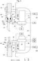
- the engagement hole 12h in a circular hole shape or in an elongated hole shape is formed in the central portion of the punch tool 12 in the width direction so as to penetrate in the front-back direction.
- an engagement groove 12g for preventing the punch tool 12 from dropping is formed (see Figure 3 ).
- An engagement hole 14h in a circular hole shape or in an elongated hole shape is formed in the central portion of the die tool 14 in the width direction so as to penetrate in the front-back direction (see Figure 3 ).
- the bending system 10 includes a press brake 16 for bending a work W by the cooperation of the punch tool 12 and the die tool 14.
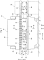
- the press brake 16 includes a main frame 18.
- the main frame 18 includes a pair of side plates 20 that are separated from each other in the left-right direction and face each other, and a plurality of connecting members 22 that connect the pair of side plates 20 to each other.
- a lower table 24 extending in the left-right direction is disposed at the lower part of the main frame 18.
- An upper table 26 extending in the left-right direction is disposed at the upper part of the main frame 18 so as to be vertically movable.
- a hydraulic cylinder 28 is disposed at the upper part of each side plate 20 as a vertical moving unit for vertically moving the upper table 26.
- the lower table 24 may be configured to be vertically movable.
- a servo motor (not illustrated) may be used as the vertical moving unit.
- Each upper tool holder 30 retains the punch tool 12 in an installable and removable manner.
- Each upper tool holder 30 has a known configuration, for example, shown in Patent Literature 2 and includes a holder main body 34.
- a front clamp plate 36 for pressing the shank 12s of the punch tool 12 in a rearward direction is disposed on a front side of each holder main body 34 so as to be swingable.
- Each front clamp plate 36 includes, on a lower end side thereof, a pawl 36c that can be engaged in an engagement groove 12g of the punch tool 12.
- a rear clamp plate 38 for pressing, in a forward direction, the shank 12s of the punch tool 12 in a state in which the front and back sides are inverted (in the front-back direction) is disposed on a rear side of each holder main body 34 so as to be swingable.
- Each rear clamp plate 38 includes, on a lower end side thereof, a pawl 38c that can be engaged in the engagement groove 12g of the punch tool 12 in the state in which the front and back sides are inverted.
- a lower tool holder 40 extending in the left-right direction is disposed on the upper side of the lower table 24.
- the lower tool holder 40 retains the die tool 14 in an installable and removable manner.
- a holder groove 40g having a known configuration, for example, shown in Patent Literatures 2 and 3, for allowing a shank 14s of the die tool 14 to be inserted into is formed on the lower tool holder 40 along the left-right direction.
- the lower tool holder 40 includes a clamper 42 for securing (pressing) the die tool 14.
- An upper joint block 44 extending in the left-right direction is disposed on the right side portion of the upper table 26.
- a joint groove 44g for allowing the shank 12s of the punch tool 12 to be inserted into is formed on the upper joint block 44 along the left-right direction.
- the joint grooves 44g of the upper joint blocks 44 are placed in series along the left-right direction in respective gaps between the holder main bodies 34 and the front clamp plates 36 in the plurality of upper tool holders 30.
- a lower joint block 46 extending in the left-right direction is disposed on the right side portion of the lower table 24.
- a joint groove 46g for allowing the shank 14s of the die tool 14 to be inserted into is formed on the lower joint block 46 along the left-right direction.
- the joint groove 46g of the lower joint block 46 is connected to the holder groove 40g of the lower tool holder 40.
- An upper support beam 48 extending in the left-right direction is disposed on the back side (rear side) of the upper table 26 via a plurality of brackets 50 (only one is illustrated).
- the upper support beam 48 projects to the right of the upper joint block 44.
- a lower support beam 52 extending in the left-right direction is disposed on the back side of the lower table 24 via a plurality of brackets 54 (only one is illustrated).
- the lower support beam 52 projects to the right of the lower joint block 46.
- the tool storage 56 for storing the plurality of punch tools 12 and the plurality of die tools 14 is placed on the lateral side of the press brake 16 in the left-right direction (an example of the vicinity of the press brake 16).
- the tool storage 56 has, for example, the same configuration as the known configurations shown in Patent Literatures 1 and 3.
- the tool storage 56 includes a plurality of upper stockers 58 (only one is illustrated) for retaining the plurality of punch tools 12. Although only the upper stocker 58 positioned at an upper exchange position for exchanging the punch tool 12 is illustrated, the plurality of upper stockers 58 are placed along the front-back direction. Each upper stocker 58 extends in the left-right direction. A stocker groove 58g for allowing the shank 12s of the punch tool 12 to be inserted into is formed along the left-right direction on each upper stocker 58. Each upper stocker 58 includes an engagement plate 60 that can be engaged in an engagement groove 12g of the punch tool 12.
- Any selected upper stocker 58 is configured to be able to be positioned at the upper exchange position by an upper stocker moving mechanism (not illustrated).
- the upper stocker 58 positioned at the upper exchange position is supported by a pair of upper receiving members 62 disposed on the right end side of the front surface of the upper support beam 48.
- the tool storage 56 includes a plurality of lower stockers 64 (only one is illustrated) for retaining the plurality of die tools 14. Although only the lower stocker 64 positioned at a lower exchange position for exchanging the die tool 14 is illustrated, the plurality of lower stockers 64 are placed along the front-back direction. Each lower stocker 64 extends in the left-right direction. A stocker groove 64g for allowing the shank 14s of the die tool 14 is inserted into is formed along the left-right direction on each lower stocker 64. Any selected lower stocker 64 is configured to be able to be positioned at the lower exchange position by a lower stocker moving mechanism (not illustrated). The lower stocker 64 positioned at the lower exchange position is supported by a pair of lower receiving members 66 disposed on the right end side of the front surface of the lower support beam 52.
- an upper guide rail 68 extending in the left-right direction is disposed on the back surface (rear surface) of the upper support beam 48.
- a pair of upper tool exchange units 70 for exchanging the punch tool 12 for the plurality of upper tool holders 30 and the upper stocker 58 positioned at the upper exchange position are disposed so as to be movable in the left-right direction.
- the pair of upper tool exchange units 70 are disposed on the back side of the upper table 26 via the upper support beam 48 and the upper guide rail 68 so as to be movable in the left-right direction.
- Each upper tool exchange unit 70 transports the punch tool 12 between the upper tool holder 30 and the upper stocker 58 positioned at the upper exchange position.
- the pair of upper tool exchange units 70 includes a first upper tool exchange unit 70 and a second upper tool exchange unit 70.
- Each upper tool exchange unit 70 has the same configuration as the known configuration shown in Patent Literature 1.
- Each upper tool exchange unit 70 includes an upper unit main body 72 and an upper support member 74.
- Each upper unit main body 72 is disposed on the upper guide rail 68 so as to be movable in the left-right direction.
- Each upper support member 74 is disposed on the upper unit main body 72 so as to be movable in the front-back direction.
- Each upper support member 74 moves in the front-back direction with respect to each upper unit main body 72 by a drive of an air cylinder 76 as a front-back moving unit disposed at an appropriate position of each upper unit main body 72.
- the upper support member 74 may be configured to be vertically movable with respect to the upper unit main body 72.
- Each upper tool exchange unit 70 includes an upper tool retention member 78 that is disposed on each upper support member 74 so as to be movable in the front-back direction and retains the punch tool 12.
- the distal end side of each upper tool retention member 78 is formed in a round-bar shape or a hook shape.
- Each upper tool retention member 78 is engageable-with and disengageable-from an engagement hole 12h of the punch tool 12.
- Each upper tool retention member 78 moves in the front-back direction with respect to each upper support member 74 by a drive of an air cylinder 80 as another front-back moving unit disposed at an appropriate position of each upper support member 74.
- a servo motor 82 as a left-right moving unit configured to move each upper tool exchange unit 70 in the left-right direction is disposed at an appropriate position of each upper unit main body 72.
- Each servo motor 82 includes an encoder 84 as a position detector for detecting the position of each upper tool exchange unit 70 (each upper tool retention member 78) in the left-right direction.
- Each servo motor 82 includes a first servo motor 82 and a second servo motor 82.
- Each encoder 84 includes a first encoder 84 and a second encoder 84.
- a lower guide rail 86 extending in the left-right direction is disposed on the back surface of the lower support beam 52.
- a pair of lower tool exchange units 88 for exchanging the die tool 14 for the plurality of lower tool holders 40 and the lower stocker 64 positioned at the lower exchange position are disposed so as to be movable in the left-right direction.
- the pair of lower tool exchange units 88 are disposed on the back side of the lower table 24 via the lower support beam 52 and the lower guide rail 86 so as to be movable in the left-right direction.
- Each lower tool exchange unit 88 transports the die tool 14 between the lower tool holder 40 and the lower stocker 64 positioned at the lower exchange position.
- the pair of lower tool exchange units 88 includes a first lower tool exchange unit 88 and a second lower tool exchange unit 88.
- Each lower tool exchange unit 88 has the same configuration as the known configuration shown in Patent Literature 1.
- Each lower tool exchange unit 88 includes a lower unit main body 90 and a lower support member 92.
- the lower unit main body 90 is disposed on the lower guide rail 86 so as to be movable in the left-right direction.
- the lower support member 92 is disposed on the lower unit main body 90 so as to be movable in the front-back direction and vertically.
- Each lower support member 92 moves in the front-back direction with respect to each lower unit main body 90 by a drive of an air cylinder 94 as a front-back moving unit disposed at an appropriate position of each lower unit main body 90.
- Each lower support member 92 moves vertically with respect to each lower unit main body 90 by a drive of an air cylinder 96 as a vertical moving unit disposed at an appropriate position of each lower unit main body 90.
- Each lower tool exchange unit 88 includes a lower tool retention member 98 that is disposed on each lower support member 92 so as to be movable in the front-back direction and retains the die tool 14.
- the distal end side of each lower tool retention member 98 is formed in a round-bar shape or a hook shape.
- Each lower tool retention member 98 is engageable-with and disengageable-from an engagement hole 14h of the die tool 14.
- Each lower tool retention member 98 moves in the front-back direction with respect to each lower support member 92 by a drive of an air cylinder 100 as another front-back moving unit disposed at an appropriate position of each lower support member 92.
- a servo motor 102 as a left-right moving unit configured to move each lower tool exchange unit 88 in the left-right direction is disposed at an appropriate position of each lower unit main body 90.
- Each servo motor 102 includes an encoder 104 as a position detector for detecting the position of each lower tool exchange unit 88 (each lower tool retention member 98) in the left-right direction.
- Each servo motor 102 includes a first servo motor 102 and a second servo motor 102.
- Each encoder 104 includes a first encoder 104 and a second encoder 104.
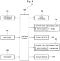
- the bending system 10 includes a control device (an NC device) 106 as a control unit.
- the control device 106 controls the hydraulic cylinder 28 and the like on the basis of a processing program, and controls the tool storage 56, the upper tool exchange unit 70, and the like on the basis of a tool exchange program.
- the control device 106 is configured with a computer.
- the encoders 84, 104, and the like are connected to the control device 106.
- the control device 106 includes a memory (not illustrated) for storing the processing program, the tool exchange program, and the like, and a CPU (not illustrated) for executing the processing program and the tool exchange program.
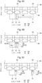
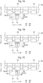
- the control device 106 controls the first upper tool exchange unit 70 and the first servo motor 82 so that the upper tool retention member 78 of the first upper tool exchange unit 70 retains the predetermined punch tool 12 in a state of being engaged in the engagement hole 12h of the predetermined punch tool 12. Further, the control device 106 controls the second upper tool exchange unit 70 and the second servo motor 82 so that the upper tool retention member 78 of the second upper tool exchange unit 70 retains the other punch tool 12' in a state of being engaged in an engagement hole 12h' of the other punch tool 12' (see Figure 5B ).
- control device 106 controls each servo motor 82 so that the first upper tool exchange unit 70 moves in the left-right direction until a target position is reached while acquiring the detection result from the first encoder 84 in a state in which a movement of the second upper tool exchange unit 70 in the left-right direction is stopped (see Figure 5C ).
- control device 106 can grasp that the predetermined punch tool 12 is in contact with the adjacent other punch tools 12' in the plurality of upper tool holders 30 on the basis of the tool exchange program.
- the control device 106 controls the first upper tool exchange unit 70 and the first servo motor 82 so that the upper tool retention member 78 of the first upper tool exchange unit 70 retains the last punch tool 12 (the punch tool 12 on the left side in Figures 6A to 6E ) from among the plurality of predetermined punch tools 12 in a state of being engaged in the engagement hole 12h of the last punch tool 12.
- control device 106 controls the second upper tool exchange unit 70 and the second servo motor 82 so that the upper tool retention member 78 of the second upper tool exchange unit 70 retains the other punch tool 12' in a state of being engaged in the engagement hole 12h' of the other punch tool 12' (see Figure 6B ). Subsequently, the control device 106 controls each servo motor 82 so that the first upper tool exchange unit 70 moves in the left-right direction by a predetermined amount while acquiring the detection result from the first encoder 84 in a state in which the movement of the second upper tool exchange unit 70 in the left-right direction is stopped (see Figure 6C ).
- the predetermined amount is a movement amount set in advance for separating the last punch tool 12 from the other punch tool 12'.
- the control device 106 controls the first upper tool exchange unit 70 and the first servo motor 82 so that the upper tool retention member 78 of the first upper tool exchange unit 70 retains a leading punch tool 12 (the punch tool 12 on the right side in Figures 6A to 6E ) from among the plurality of predetermined punch tools in a state of being engaged in the engagement hole 12h of the leading punch tool 12. Further, the control device 106 controls the second upper tool exchange unit 70 and the second servo motor 82 so that the upper tool retention member 78 of the second upper tool exchange unit 70 retains the last punch tool 12 in a state of being engaged in the engagement hole 12h of the last punch tool 12(see Figure 6D ).
- control device 106 controls each servo motor 82 so that each upper tool exchange unit 70 moves in the left-right direction synchronously (or asynchronously) until a target position is reached while acquiring the detection result from each encoder 84 (see Figure 6E ).
- the plurality of predetermined punch tools 12 may include an intermediate punch tool (not illustrated) that is between the leading punch tool 12 and the last punch tool 12.
- the number of predetermined punch tools 12 may be three or more.
- each servo motor 82 may be controlled to be moved in the left-right direction until the target position is reached.
- control device 106 may control each upper tool exchange unit 70 and each servo motor 82 as follows.
- control device 106 control the first upper tool exchange unit 70 and the first servo motor 82 so that the upper tool retention member 78 of the first upper tool exchange unit 70 retains the leading punch tool 12 in a state of being engaged in the engagement hole 12h of the leading punch tool 12. Further, the control device 106 control the second upper tool exchange unit 70 and the second servo motor 82 so that the upper tool retention member 78 of the second upper tool exchange unit 70 retains the last punch tool 12 in a state of being engaged in the engagement hole 12h of the last punch tool 12 (see Figure 7A ).
- the control device 106 controls each servo motor 82 so that the first upper tool exchange unit 70 moves in the left-right direction by a predetermined amount while acquiring the detection result from the first encoder 84 in a state in which the movement of the second upper tool exchange unit 70 in the left-right direction is stopped (see Figure 7B ).
- the predetermined amount is a movement amount set in advance for separating the leading punch tool 12 from the last punch tool 12.
- the control device 106 When the predetermined punch tool 12 to be exchanged (to be transported) is in contact with the adjacent other punch tool 12' not to be exchanged not only in the plurality of upper tool holders 30 but also in the upper stocker 58 positioned at the upper exchange position, the control device 106 also controls each upper tool exchange unit 70 and each servo motor 82 in the same manner as described above. Further, when the predetermined die tool 14 to be exchanged (to be transported) is in contact with the adjacent other die tool not to be exchanged (not illustrated) on the lower tool holder 40 and in the lower stocker 64 positioned at the lower exchange position, the control device 106 also controls each lower tool exchange unit 88 and each servo motor 102 in the same manner as described above.
- the control device 106 controls the servo motor 82 to move the upper tool exchange unit 70 in the left-right direction so that the upper tool retention member 78 is opposed to the engagement hole 12h of the punch tool 12 installed in the upper tool holder 30.
- the control device 106 causes the upper tool retention member 78 to retain the punch tool 12 while engaging the upper tool retention member 78 in the engagement hole 12h of the punch tool 12.
- the control device 106 controls the servo motor 82 to move the upper tool exchange unit 70 to the right so that the punch tool 12 is transported to the right and removed from the upper tool holder 30.
- control device 106 controls the servo motor 82 to move the upper tool exchange unit 70 to the right so that the punch tool 12 is transported to the right and installed in the upper stocker 58. Thereafter, the control device 106 causes the upper tool retention member 78 to be removed from the engagement hole 12h of the punch tool 12 so that the punch tool 12 is released from a state in which the punch tool 12 is retained by the upper tool retention member 78.
- the punch tool 12 may be moved to the back side (rear side) of the upper table 26 by the upper tool exchange unit 70 after the punch tool 12 is removed from the upper tool holder 30.
- the die tool 14 When the die tool 14 is transported between the lower tool holder 40 and the lower stocker 64 positioned at the lower exchange position, the operation similar to the above is performed. As a result, the die tool 14 installed in the lower tool holder 40 and the die tool 14 installed in the lower stocker 64 can be automatically exchanged.
- the die tool 14 when the die tool 14 is installed in and removed from the lower tool holder 40 or the lower stocker 64, the die tool 14 may be moved vertically by the lower tool exchange unit 88.
- the tool transport method according to the present embodiment is a method of transporting the tools 12 and 14 along the tool holders 30 and 40 or the stockers 58 and 64 positioned at the exchange positions.
- control device 106 controls each upper tool exchange unit 70 and each servo motor 82 so as to operate as follows.
- the predetermined punch tool 12 is retained in a state in which the upper tool retention member 78 of the first upper tool exchange unit 70 is engaged in the engagement hole 12h of the predetermined punch tool 12. Further, the other punch tool 12' is retained in a state in which the upper tool retention member 78 of the second upper tool exchange unit 70 is engaged in the engagement hole 12h' of the other punch tool 12' (see Figure 5B ). Subsequently, the first upper tool exchange unit 70 moves in the left-right direction until a target position is reached while acquiring the detection result from the first encoder 84 in a state in which the movement of the second upper tool exchange unit 70 in the left-right direction is stopped (see Figure 5C ).
- the position of the other punch tool 12' is not shifted because the other punch tool 12' is not dragged by the predetermined punch tools 12. Therefore, without performing post-processing on a side surface of the punch tool 12, only the predetermined punch tool 12 to be exchanged can be transported in the left-right direction by the upper tool exchange unit 70.
- control device 106 controls each upper tool exchange unit 70 and each servo motor 82 so as to operate as follows.
- the last punch tool 12 is retained in a state in which the upper tool retention member 78 of the first upper tool exchange unit 70 is engaged in the engagement hole 12h of the last punch tool 12 from among the plurality of predetermined punch tools 12.
- the other punch tool 12' is retained in a state in which the upper tool retention member 78 of the second upper tool exchange unit 70 is engaged in the engagement hole 12h' of the other punch tool 12' (see Figure 6B ).
- the first upper tool exchange unit 70 moves in the left-right direction by a predetermined amount in a state in which the movement of the second upper tool exchange unit 70 in the left-right direction is stopped (see Figure 6C ).
- the plurality of predetermined punch tools 12 can be separated from the other punch tools 12'.
- the upper tool retention member 78 of the first upper tool exchange unit 70 retains the leading punch tool 12 in a state of being engaged in the engagement hole 12h of the leading punch tool 12 from among the plurality of predetermined punch tools 12. Further, the upper tool retention member 78 of the second upper tool exchange unit 70 retains the last punch tool 12 in a state of being engaged in the engagement hole 12h of the last punch tool 12 (see Figure 6D ). Subsequently, each upper tool exchange unit 70 moves in the left-right direction synchronously (or asynchronously) until a target position is reached (see Figure 6E ). As a result, the position of the other punch tool 12' is not shifted because the other punch tool 12' is not dragged by the plurality of predetermined punch tools 12. Therefore, without performing post-processing on a side surface of the punch tool 12, only the plurality of predetermined punch tools 12 to be exchanged can be transported by the upper tool exchange unit 70 in the left-right direction along the plurality of upper tool holders 30.
- control device 106 may control each upper tool exchange unit 70 and each servo motor 82 so as to operate as follows.
- the leading punch tool 12 is retained in a state in which the upper tool retention member 78 of the first upper tool exchange unit 70 is engaged in the engagement hole 12h of the leading punch tool 12. Further, the last punch tool 12 is retained in a state in which the upper tool retention member 78 of the second upper tool exchange unit 70 is engaged in the engagement hole 12h of the last punch tool 12 (see Figure 7A ). Subsequently, the upper tool exchange unit 70 moves in the left-right direction by a predetermined amount in a state in which the movement of the second upper tool exchange unit 70 in the left-right direction is stopped. As a result, the leading punch tool 12 can be separated from the last punch tool 12.
- the transport direction of the predetermined punch tool 12 is illustrated as the right direction
- the upper tool exchange unit 70 on the right side is the first upper tool exchange unit 70
- the upper tool exchange unit 70 on the left side is the second upper tool exchange unit 70.
- the upper tool exchange unit 70 on the left side is the first upper tool exchange unit 70
- the upper tool exchange unit 70 on the right side is the second upper tool exchange unit 70.
- control device 106 controls each upper tool exchange unit 70 and each servo motor 82 so as to operate in the same manner as described above when the predetermined punch tool 12 to be exchanged (to be transported) is in contact with the adjacent other punch tool 12' not to be exchanged not only in the plurality of the upper tool holder 30 but also in the upper stocker 58 positioned at the upper exchange position.
- the control device 106 When the predetermined die tool 14 (or the plurality of predetermined die tools 14) to be exchanged (to be transported) is/are in contact with the adjacent other die tool not to be exchanged (not illustrated) in the lower tool holder 40 and the lower stocker 64 positioned at the lower exchange position, the control device 106 also controls each lower tool exchange unit 88 and each servo motor 102 so as to operate in the same manner as described above. As a result, the position of the other die tool is not shifted because the other die tool is not dragged by the predetermined die tool 14 (or the plurality of predetermined die tools 14). Therefore, without performing post-processing on a side surface of the die tool 14, only the predetermined die tool 14 (or the plurality of predetermined die tools 14) can be transported by the lower tool exchange unit 88 in the left-right direction along the lower tool holder 40.
- the tool exchange units 70 and 88 may be disposed on the front sides of the tables 26 and 24 so as to be movable in the left-right direction.
- the location at which the tool storage 56 is placed may be other than the lateral side of the press brake 16 in the left-right direction as long as the location is in the vicinity of the press brake 16.
- a bending system includes a tool storage placed in a vicinity of a press brake and including a plurality of stockers extending in a left-right direction so as to be able to retain a plurality of tools, a first tool exchange unit and a second tool exchange unit each disposed on a back side or a front side of a table of the press brake so as to be movable in the left-right direction and configured to exchange a tool with respect to a tool holder of the press brake and a stocker selected from among the plurality of stockers, a left-right moving unit configured to move the first tool exchange unit and the second tool exchange unit in the left-right direction, respectively, and a control unit configured to control the first tool exchange unit, the second tool exchange unit, and the left-right moving unit.
- the first tool exchange unit includes a first tool retention member engageable-with and disengageable-from an engagement hole of a tool, the first tool retention member being able to retain the tool and configured to move in the left-right direction together with the first tool exchange unit.
- the second tool exchange unit includes a second tool retention member engageable-with and disengageable-from an engagement hole of a tool, the second tool retention member being able to retain the tool and configured to move in the left-right direction together with the second tool exchange unit.
- the control unit when a first tool to be exchanged is in contact with an adjacent second tool not to be exchanged in the tool holder or the selected stocker, controls the first tool exchange unit, the second tool exchange unit, and the left-right moving unit such that the first tool retention member retains the first tool in a state of being engaged in an engagement hole of the first tool, the second tool retention member retains the second tool in a state of being engaged in an engagement hole of the second tool, and the first tool exchange unit subsequently moves in the left-right direction in a state in which a movement of the second tool exchange unit in the left-right direction is stopped.
- the second tool not to be exchanged since the second tool not to be exchanged is not dragged by the first tool to be exchanged, the position of the second tool is not shifted.
- the first tool to be exchanged can be transported in the left-right direction by the first and second tool exchange units without performing post-processing on a side surface of the tool. Therefore, it is possible to stably perform an operation related to automatic exchange of tools while suppressing an increase in manufacturing cost of the tools.
- the control unit may control the first tool exchange unit, the second tool exchange unit, and the left-right moving unit such that the first tool retention member retains a last tool from among the plurality of first tools in a state of being engaged in an engagement hole of the last tool, the last tool being in contact with the second tool, the second tool retention member retains the second tool in a state of being engaged in the engagement hole of the second tool, the first tool exchange unit subsequently moves in the left-right direction by a predetermined amount in a state in which the movement of the second tool exchange unit in the left-right direction is stopped, the first tool retention member thereafter retains a leading tool from among the plurality of first tools in a state of being engaged in an engagement hole of the leading tool, the second tool retention member retains the last tool in a state of being engaged in the engagement hole of the last tool, and the first tool exchange unit and the second tool exchange unit then move in the left-right direction.
- the control unit may control the first tool exchange unit, the second tool exchange unit, and the left-right moving unit such that the first tool retention member retains the leading tool in a state of being engaged in the engagement hole of the leading tool, the second tool retention member retains the last tool in a state of being engaged in the engagement hole of the last tool, and the first tool exchange unit subsequently moves in the left-right direction by a predetermined amount in a state in which the movement of the second tool exchange unit in the left-right direction is stopped.
- a tool transport method uses a first tool exchange unit and a second tool exchange unit each disposed on a back side or a front side of a table of a press brake so as to be movable in a left-right direction.
- the tool transport method includes, when a first tool to be exchanged is in contact with an adjacent second tool not to be exchanged in a tool holder of the press brake or in a selected stocker in a tool storage placed in a vicinity of the press brake, retaining, by a first tool retention member of the first tool exchange unit, the first tool in a state in which the first tool retention member is engaged in an engagement hole of the first tool, retaining, by a second tool retention member of the second tool exchange unit, the second tool in a state in which the second tool retention member is engaged in an engagement hole of the second tool, and subsequently moving the first tool exchange unit in the left-right direction in a state in which a movement of the second tool exchange unit in the left-right direction is stopped.
- the second tool not to be exchanged since the second tool not to be exchanged is not dragged by the first tool to be exchanged, the position of the second tool is not shifted.
- the first tool to be exchanged can be transported in the left-right direction by the first and second tool exchange units without performing post-processing on a side surface of the tool. Therefore, it is possible to stably perform an operation related to automatic exchange of tools while suppressing an increase in manufacturing cost of the tools.
- the tool transport method described above may include, when the first tool includes a plurality of first tools, retaining, by the first tool retention member, a last tool from among the plurality of first tools in a state in which the first tool retention member is engaged in an engagement hole of the last tool, the last tool being in contact with the second tool, retaining, by the second tool retention member, the second tool in a state in which the second tool retention member is engaged in the engagement hole of the second tool, subsequently moving the first tool exchange unit in the left-right direction by a predetermined amount in a state in which the movement of the second tool exchange unit in the left-right direction is stopped, thereafter retaining, by the first tool retention member, a leading tool from among the plurality of first tools in a state in which the first tool retention member is engaged in an engagement hole of the leading tool, retaining, by the second tool retention member, the last tool in a state in which the second tool retention member is engaged in the engagement hole of the last tool, and then moving the first tool exchange unit and the second tool exchange unit in the left-right
- the tool transport method described above may include, before retaining the last tool by the first tool retention member, retaining, by the first tool retention member, the leading tool in a state in which the first tool retention member is engaged in the engagement hole of the leading tool, retaining, by the second tool retention member, the last tool in a state in which the second tool retention member is engaged in the engagement hole of the last tool, and subsequently moving the first tool exchange unit in the left-right direction by a predetermined amount in a state in which the movement of the second tool exchange unit in the left-right direction is stopped.
Landscapes
- Engineering & Computer Science (AREA)
- Mechanical Engineering (AREA)
- Mounting, Exchange, And Manufacturing Of Dies (AREA)
- Bending Of Plates, Rods, And Pipes (AREA)
Claims (6)
- Ein Biegesystem (10) umfassend:ein Werkzeuglager (56), das in der Nähe einer Abkantpresse (16) angeordnet ist und eine Vielzahl von Lagern (58, 64) aufweist, die sich in einer Links-Rechts-Richtung erstrecken, um eine Vielzahl von Werkzeugen (12, 14) aufnehmen zu können;eine erste Werkzeugwechseleinheit (70, 88) und eine zweite Werkzeugwechseleinheit (70, 88), die jeweils auf einer Rückseite oder einer Vorderseite eines Tisches (26, 24) der Abkantpresse (16) angeordnet sind, um in der Links-Rechts-Richtung beweglich zu sein, und die konfiguriert sind ein Werkzeug (12, 14) in Bezug auf einen Werkzeughalter (30, 40) der Abkantpresse (16) und einen Vorratsbehälter (58, 64), der aus der Vielzahl der Vorratsbehälter (58, 64) ausgewählt ist, auszutauschen;a eine Links-Rechts-Bewegungseinheit (82, 102), die konfiguriert ist die erste Werkzeugwechseleinheit (70, 88) und die zweite Werkzeugwechseleinheit (70, 88) jeweils in der Links-Rechts-Richtung zu bewegen; undeine Steuereinheit (106), die zum Steuern der ersten Werkzeugwechseleinheit (70, 88), der zweiten Werkzeugwechseleinheit (70, 88) und der Links-Rechts-Bewegungseinheit (82, 102) konfiguriert ist, wobeidie erste Werkzeugwechseleinheit (70, 88) ein erstes Werkzeughalteelement (78, 98) aufweist, das mit einer Eingriffsöffnung (12h, 14h) eines Werkzeugs (12, 14) in Eingriff bringbar und davon lösbar ist, wobei das erste Werkzeughalteelement (78, 98) in der Lage ist, das Werkzeug (12, 14) zu halten, und konfiguriert ist sich zusammen mit der ersten Werkzeugwechseleinheit (70, 88) in der Links-Rechts-Richtung zu bewegen, unddie zweite Werkzeugwechseleinheit (70, 88) ein zweites Werkzeughalteelement (78, 98) aufweist, das mit einer Eingriffsöffnung (12h, 14h) eines Werkzeugs (12, 14) in Eingriff bringbar und davon lösbar ist, wobei das zweite Werkzeughalteelement (78, 98) in der Lage ist, das Werkzeug (12, 14) zu halten, und konfiguriert ist sich zusammen mit der zweiten Werkzeugwechseleinheit (70, 88) in der Links-Rechts-Richtung zu bewegen,dadurch gekennzeichnet, dassdie Steuereinheit (106) die erste Werkzeugwechseleinheit (70, 88), die zweite Werkzeugwechseleinheit (70, 88) und die Links-Rechts-Bewegungseinheit (82, 102) steuert, wenn ein auszutauschendes erstes Werkzeug (12, 14) in Kontakt mit einem benachbarten, nicht auszutauschenden zweiten Werkzeug (12') in dem Werkzeughalter (30, 40) oder dem ausgewählten Lager (58, 64) ist, so dassdas erste Werkzeughalteelement (78, 98) das erste Werkzeug (12, 14) in einem Zustand hält, in dem es in einer Eingriffsöffnung (12h, 14h) des ersten Werkzeugs (12, 14) in Eingriff ist, und das zweite Werkzeughalteelement (78, 98) das zweite Werkzeug (12') in einem Zustand hält, in dem es in einer Eingriffsöffnung (12h') des zweiten Werkzeugs (12') in Eingriff ist, unddie erste Werkzeugwechseleinheit (70, 88) sich anschließend in der Links-Rechts-Richtung in einem Zustand bewegt, in dem eine Bewegung der zweiten Werkzeugwechseleinheit (70, 88) in der Links-Rechts-Richtung angehalten wird.
- Das Biegesystem (10) gemäß Anspruch 1, wobeidie Steuereinheit (106), wenn das erste Werkzeug (12, 14) eine Vielzahl von ersten Werkzeugen (12, 14) umfasst, die erste Werkzeugwechseleinheit (70, 88), die zweite Werkzeugwechseleinheit (70, 88) und die Links-Rechts-Bewegungseinheit (82, 102) so steuert, dassdas erste Werkzeughalteelement (78, 98) ein letztes Werkzeug (12, 14) aus der Vielzahl der ersten Werkzeuge (12, 14) in einem Zustand hält, in dem es in eine Eingriffsöffnung (12h, 14h) des letzten Werkzeugs (12, 14) eingreift, wobei das letzte Werkzeug (12, 14) in Kontakt mit dem zweiten Werkzeug (12') steht, und das zweite Werkzeughalteelement (78, 98) das zweite Werkzeug (12') in einem Zustand hält, in dem es in die Eingriffsöffnung (12h') des zweiten Werkzeugs (12') eingreift,die erste Werkzeugwechseleinheit (70, 88) sich anschließend in der Links-Rechts-Richtung um einen vorbestimmten Betrag in einem Zustand bewegt, in dem die Bewegung der zweiten Werkzeugwechseleinheit (70, 88) in der Links-Rechts-Richtung angehalten ist,das erste Werkzeughalteelement (78, 98) danach ein führendes Werkzeug (12, 14) aus der Vielzahl der ersten Werkzeuge (12, 14) in einem Zustand hält, in dem es in eine Eingriffsöffnung (12h, 14h) des führenden Werkzeugs (12, 14) eingreift, und das zweite Werkzeughalteelement (78, 98) das letzte Werkzeug (12, 14) in einem Zustand hält, in dem es in die Eingriffsöffnung (12h, 14h) des letzten Werkzeugs (12, 14) eingreift, unddie erste Werkzeugwechseleinheit (70, 88) und die zweite Werkzeugwechseleinheit (70, 88) sich dann in der Links-Rechts-Richtung bewegen.
- Das Biegesystem (10) gemäß Anspruch 2, wobeidie Steuereinheit (106), bevor das erste Werkzeughalteelement (78, 98) das letzte Werkzeug (12, 14) zurückhält, die erste Werkzeugwechseleinheit (70, 88), die zweite Werkzeugwechseleinheit (70, 88) und die Links-Rechts-Bewegungseinheit (82, 102) so steuert, dassdas erste Werkzeughalteelement (78, 98) das führende Werkzeug (12, 14) in einem Zustand hält, in dem es in die Eingriffsöffnung (12h, 14h) des führenden Werkzeugs (12, 14) eingreift, und das zweite Werkzeughalteelement (78, 98) das letzte Werkzeug (12, 14) in einem Zustand hält, in dem es in die Eingriffsöffnung (12h, 14h) des letzten Werkzeugs (12, 14) eingreift, unddie erste Werkzeugwechseleinheit (70, 88) sich anschließend in der Links-Rechts-Richtung um einen vorbestimmten Betrag in einem Zustand bewegt, in dem die Bewegung der zweiten Werkzeugwechseleinheit (70, 88) in der Links-Rechts-Richtung angehalten ist.
- Ein Verfahren zum Transport von Werkzeugen unter Verwendung einer ersten Werkzeugwechseleinheit (70, 88) und einer zweiten Werkzeugwechseleinheit (70, 88), die jeweils auf einer Rückseite oder einer Vorderseite eines Tisches (26, 24) einer Abkantpresse (16) angeordnet sind, so dass sie in einer Links-Rechts-Richtung beweglich sind,
gekennzeichnet dadurch, dass
das Werkzeugtransportverfahren, wenn ein erstes auszutauschendes Werkzeug (12, 14) mit einem benachbarten, nicht auszutauschenden zweiten Werkzeug (12') in einem Werkzeughalter (30, 40) der Abkantpresse (16) oder in einem ausgewählten Lager (58, 64) in einem Werkzeugspeicher (56), der in der Nähe der Abkantpresse (16) angeordnet ist, in Kontakt ist, umfasst:Halten des ersten Werkzeugs (12, 14) durch ein erstes Werkzeughalteelement (78, 98) der ersten Werkzeugwechseleinheit (70, 88) in einem Zustand, in dem das erste Werkzeughalteelement (78, 98) in eine Eingriffsöffnung (12h, 14h) des ersten Werkzeugs (12, 14) eingreift, und Halten des zweiten Werkzeugs (12') durch ein zweites Werkzeughalteelement (78, 98) der zweiten Werkzeugwechseleinheit (70, 88) in einem Zustand, in dem das zweite Werkzeughalteelement (78, 98) in eine Eingriffsöffnung (12h') des zweiten Werkzeugs (12') eingreift; undanschließendes Bewegen der ersten Werkzeugwechseleinheit (70, 88) in der Links-Rechts-Richtung in einem Zustand, in dem eine Bewegung der zweiten Werkzeugwechseleinheit (70, 88) in der Links-Rechts-Richtung angehalten ist. - Das Verfahren zum Transport von Werkzeugen gemäß Anspruch 4, des Weiteren umfassend, wenn das erste Werkzeug (12, 14) eine Vielzahl von ersten Werkzeugen (12, 14) umfasst:Halten eines letzten Werkzeugs (12, 14) aus der Vielzahl der ersten Werkzeuge (12, 14) durch das erste Werkzeughalteelement (78, 98) in einem Zustand, in dem das erste Werkzeughalteelement (78, 98) in eine Eingriffsöffnung (12h, 14h) des letzten Werkzeugs (12, 14) eingreift, wobei das letzte Werkzeug (12, 14) in Kontakt mit dem zweiten Werkzeug (12') steht, und Halten des zweiten Werkzeugs (12') durch das zweite Werkzeughalteelement (78, 98) in einem Zustand, in dem das zweite Werkzeughalteelement (78, 98) in die Eingriffsöffnung (12h') des zweiten Werkzeugs (12') eingreift;anschließendes Bewegen der ersten Werkzeugwechseleinheit (70, 88) in der Links-Rechts-Richtung um einen vorbestimmten Betrag in einem Zustand, in dem die Bewegung der zweiten Werkzeugwechseleinheit (70, 88) in der Links-Rechts-Richtung angehalten wird;anschließendes Halten eines führenden Werkzeugs (12, 14) aus der Vielzahl der ersten Werkzeuge (12, 14) durch das erste Werkzeughalteelement (78, 98) in einem Zustand, in dem das erste Werkzeughalteelement (78, 98) in eine Eingriffsöffnung (12h, 14h) des führenden Werkzeugs (12, 14) eingreift, und Halten des letzten Werkzeugs (12, 14) durch das zweite Werkzeughalteelement (78, 98) in einem Zustand, in dem das zweite Werkzeughalteelement (78, 98) in die Eingriffsöffnung (12h, 14h) des letzten Werkzeugs (12, 14) eingreift; undanschließendes Bewegen der ersten Werkzeugwechseleinheit (70, 88) und der zweiten Werkzeugwechseleinheit (70, 88) in der Links-Rechts-Richtung.
- Das Verfahren zum Transport von Werkzeugen gemäß Anspruch 4, des Weiteren umfassend, vor dem Halten des letzten Werkzeugs (12, 14) durch das erste Werkzeughalteelement (78, 98):Halten des führenden Werkzeugs (12, 14) durch das erste Werkzeughalteelement (78, 98) in einem Zustand, in dem das erste Werkzeughalteelement (78, 98) in die Eingriffsöffnung (12h, 14h) des führenden Werkzeugs (12, 14) eingreift, und Halten des letzten Werkzeugs (12, 14) durch das zweite Werkzeughalteelement (78, 98) in einem Zustand, in dem das zweite Werkzeughalteelement (78, 98) in die Eingriffsöffnung (12h, 14h) des letzten Werkzeugs (12, 14) eingreift; undanschließendes Bewegen der ersten Werkzeugwechseleinheit (70, 88) in der Links-Rechts-Richtung um einen vorbestimmten Betrag in einem Zustand, in dem die Bewegung der zweiten Werkzeugwechseleinheit (70, 88) in der Links-Rechts-Richtung angehalten ist.
Applications Claiming Priority (2)
| Application Number | Priority Date | Filing Date | Title |
|---|---|---|---|
| JP2019092890A JP6741824B1 (ja) | 2019-05-16 | 2019-05-16 | 曲げ加工システム及び金型移送方法 |
| PCT/JP2020/018708 WO2020230730A1 (ja) | 2019-05-16 | 2020-05-08 | 曲げ加工システム及び金型移送方法 |
Publications (3)
| Publication Number | Publication Date |
|---|---|
| EP3970874A1 EP3970874A1 (de) | 2022-03-23 |
| EP3970874A4 EP3970874A4 (de) | 2022-07-13 |
| EP3970874B1 true EP3970874B1 (de) | 2023-05-31 |
Family
ID=72047802
Family Applications (1)
| Application Number | Title | Priority Date | Filing Date |
|---|---|---|---|
| EP20804835.5A Active EP3970874B1 (de) | 2019-05-16 | 2020-05-08 | Biegesystem und werkzeugtransferprozess |
Country Status (5)
| Country | Link |
|---|---|
| US (1) | US12145191B2 (de) |
| EP (1) | EP3970874B1 (de) |
| JP (1) | JP6741824B1 (de) |
| CN (1) | CN113840672B (de) |
| WO (1) | WO2020230730A1 (de) |
Families Citing this family (2)
| Publication number | Priority date | Publication date | Assignee | Title |
|---|---|---|---|---|
| EP4487977A1 (de) * | 2018-07-17 | 2025-01-08 | Amada Co., Ltd. | Verfahren zum anbringen einer geteilten obermatrize an einem obergesenkhalter auf einem obertisch einer abkantpresse, gesenkwechselvorrichtung und gesenkaufbewahrer |
| CN120244067A (zh) * | 2025-06-04 | 2025-07-04 | 靖江市英正五金科技有限公司 | 一种液压废钢自动送料剪切机 |
Family Cites Families (23)
| Publication number | Priority date | Publication date | Assignee | Title |
|---|---|---|---|---|
| JPS5947861B2 (ja) | 1976-12-28 | 1984-11-21 | 日本電気株式会社 | アラ−ム表示付プラズマ・ディスプレイ・パネル |
| JPS5841800B2 (ja) | 1980-08-29 | 1983-09-14 | 富士通株式会社 | セラミック多層基板の形成方法 |
| JPS5841800U (ja) | 1981-09-16 | 1983-03-19 | 三菱重工業株式会社 | 条材などの持ち上げ具 |
| JP3841923B2 (ja) * | 1997-06-20 | 2006-11-08 | 株式会社アマダ | 曲げ加工機における金型交換方法および金型格納装置並びに曲げ加工システム |
| JP4558852B2 (ja) * | 1998-08-28 | 2010-10-06 | 株式会社アマダ | 金型及び金型交換装置 |
| EP2143507B1 (de) | 1999-01-13 | 2015-08-12 | Amada Company, Limited | Biegepressensystem, Verfahren zur Montage von Werkzeugen an solch einem System und Verfahren zur Herstellung von Biegeprodukten |
| JP2004322199A (ja) * | 2003-04-30 | 2004-11-18 | Amada Co Ltd | 曲げ加工装置 |
| JP4582621B2 (ja) * | 2003-06-23 | 2010-11-17 | 株式会社アマダ | 曲げ加工装置 |
| DE602006020699D1 (de) * | 2006-06-01 | 2011-04-28 | Wila Bv | Auswechselbares Werkzeug/Manipulator Kombination |
| JP5841800B2 (ja) | 2011-10-20 | 2016-01-13 | 株式会社アマダホールディングス | 上型ホルダ |
| JP2013111610A (ja) * | 2011-11-29 | 2013-06-10 | Amada Co Ltd | 板材曲げ加工装置 |
| JP5965214B2 (ja) * | 2012-05-31 | 2016-08-03 | 株式会社アマダホールディングス | 曲げ加工装置の動作制御方法及び動作制御システム、並びに、曲げ加工作業のトレーニングシステム及びトレーニング方法 |
| JP2014004604A (ja) * | 2012-06-25 | 2014-01-16 | Amada Co Ltd | 金型搭載用ストッカ、金型格納装置、並びに金型・ハンド格納装置及びロボットによる金型交換方法とその制御装置 |
| EP3330015B1 (de) * | 2014-02-10 | 2023-06-21 | SALVAGNINI ITALIA S.p.A. | Metallblechbiegemaschine |
| JP5947861B2 (ja) | 2014-10-24 | 2016-07-06 | 株式会社アマダホールディングス | プレスブレーキの金型着脱交換方法及び金型収納装置 |
| IT201700052500A1 (it) * | 2017-05-15 | 2018-11-15 | Salvagnini Italia Spa | Macchina piegatrice per lamiere metalliche |
| JP2019092890A (ja) | 2017-11-22 | 2019-06-20 | 株式会社三洋物産 | 遊技機 |
| CN208004538U (zh) * | 2018-03-24 | 2018-10-26 | 北京铂纳艺境视觉技术有限公司 | 液压板料折弯机 |
| WO2020226084A1 (ja) * | 2019-05-07 | 2020-11-12 | 株式会社アマダ | プレスブレーキ |
| CN113825572B (zh) * | 2019-05-16 | 2024-03-15 | 株式会社天田集团 | 弯曲加工系统以及金属模具错位修正方法 |
| JP1672868S (ja) | 2020-03-27 | 2020-11-16 | 乗用自動車 | |
| WO2022059382A1 (ja) * | 2020-09-17 | 2022-03-24 | 村田機械株式会社 | 上型及び加工システム |
| JP2023041024A (ja) * | 2021-09-10 | 2023-03-23 | 株式会社アマダ | 曲げ加工システム、及び金型の配置方法 |
-
2019
- 2019-05-16 JP JP2019092890A patent/JP6741824B1/ja active Active
-
2020
- 2020-05-08 WO PCT/JP2020/018708 patent/WO2020230730A1/ja not_active Ceased
- 2020-05-08 US US17/610,484 patent/US12145191B2/en active Active
- 2020-05-08 EP EP20804835.5A patent/EP3970874B1/de active Active
- 2020-05-08 CN CN202080036296.6A patent/CN113840672B/zh active Active
Also Published As
| Publication number | Publication date |
|---|---|
| JP2020185598A (ja) | 2020-11-19 |
| EP3970874A1 (de) | 2022-03-23 |
| JP6741824B1 (ja) | 2020-08-19 |
| WO2020230730A1 (ja) | 2020-11-19 |
| EP3970874A4 (de) | 2022-07-13 |
| US12145191B2 (en) | 2024-11-19 |
| CN113840672B (zh) | 2023-08-15 |
| US20220219221A1 (en) | 2022-07-14 |
| CN113840672A (zh) | 2021-12-24 |
Similar Documents
| Publication | Publication Date | Title |
|---|---|---|
| JP4582621B2 (ja) | 曲げ加工装置 | |
| EP3970875B1 (de) | Biegesystem und verfahren zur korrektur von werkzeugfehlausrichtung | |
| JP6789356B1 (ja) | 曲げ加工システム及び金型位置ずれ補正方法 | |
| KR101871332B1 (ko) | 판금 벤딩기 | |
| EP2241425B1 (de) | Bearbeitungsverfahren von einem Bauteil aus Holz oder dergleichen, insbesondere für Bestandteile von Tür- oder Fensterrahmen | |
| JP5283932B2 (ja) | 板状の工作物の加工のための機械設備 | |
| CN102056710B (zh) | 用于机床的托盘操纵系统 | |
| EP3970874B1 (de) | Biegesystem und werkzeugtransferprozess | |
| EP3981523B1 (de) | Biegesystem | |
| RU2767100C1 (ru) | Гибочный станок для листового металла с инструментальным магазином | |
| KR20200078356A (ko) | 다단식 핸드 및 이를 구비하는 반송 로봇 | |
| JP7320439B2 (ja) | 分割金型の配置方法及びプレスブレーキ | |
| EP3808468B1 (de) | Verfahren zur befestigung von geteiltem stempel und abkantbremse | |
| KR200277129Y1 (ko) | 펀치 프레스기 | |
| CN211386496U (zh) | 直管冲压自动线 | |
| CN110788358A (zh) | 多轴对立钻床 | |
| US6554120B2 (en) | Work sheet processing system | |
| CN110666516A (zh) | 一种杆件铣缺口的自动化加工装置 | |
| CN211162012U (zh) | 多轴对立钻床 | |
| US12558717B2 (en) | Bending system, and divided tool arrangement method | |
| JP7465906B2 (ja) | 曲げ加工システム、及び分割金型の配置方法 | |
| EP4419269B1 (de) | Vorrichtung zum beladen einer presse mit biegewerkzeugen und verfahren zum beladen/entladen von werkzeugen | |
| JP4470087B2 (ja) | 物品自動穿孔装置 |
Legal Events
| Date | Code | Title | Description |
|---|---|---|---|
| STAA | Information on the status of an ep patent application or granted ep patent |
Free format text: STATUS: THE INTERNATIONAL PUBLICATION HAS BEEN MADE |
|
| PUAI | Public reference made under article 153(3) epc to a published international application that has entered the european phase |
Free format text: ORIGINAL CODE: 0009012 |
|
| STAA | Information on the status of an ep patent application or granted ep patent |
Free format text: STATUS: REQUEST FOR EXAMINATION WAS MADE |
|
| 17P | Request for examination filed |
Effective date: 20211112 |
|
| AK | Designated contracting states |
Kind code of ref document: A1 Designated state(s): AL AT BE BG CH CY CZ DE DK EE ES FI FR GB GR HR HU IE IS IT LI LT LU LV MC MK MT NL NO PL PT RO RS SE SI SK SM TR |
|
| A4 | Supplementary search report drawn up and despatched |
Effective date: 20220614 |
|
| RIC1 | Information provided on ipc code assigned before grant |
Ipc: B21D 37/04 20060101ALI20220609BHEP Ipc: B21D 5/02 20060101AFI20220609BHEP |
|
| RIN1 | Information on inventor provided before grant (corrected) |
Inventor name: YAMAGUCHI, YOHEI Inventor name: SATO, MASAAKI |
|
| DAV | Request for validation of the european patent (deleted) | ||
| DAX | Request for extension of the european patent (deleted) | ||
| GRAP | Despatch of communication of intention to grant a patent |
Free format text: ORIGINAL CODE: EPIDOSNIGR1 |
|
| STAA | Information on the status of an ep patent application or granted ep patent |
Free format text: STATUS: GRANT OF PATENT IS INTENDED |
|
| INTG | Intention to grant announced |
Effective date: 20230210 |
|
| GRAS | Grant fee paid |
Free format text: ORIGINAL CODE: EPIDOSNIGR3 |
|
| GRAA | (expected) grant |
Free format text: ORIGINAL CODE: 0009210 |
|
| STAA | Information on the status of an ep patent application or granted ep patent |
Free format text: STATUS: THE PATENT HAS BEEN GRANTED |
|
| AK | Designated contracting states |
Kind code of ref document: B1 Designated state(s): AL AT BE BG CH CY CZ DE DK EE ES FI FR GB GR HR HU IE IS IT LI LT LU LV MC MK MT NL NO PL PT RO RS SE SI SK SM TR |
|
| REG | Reference to a national code |
Ref country code: GB Ref legal event code: FG4D Ref country code: CH Ref legal event code: EP |
|
| REG | Reference to a national code |
Ref country code: DE Ref legal event code: R096 Ref document number: 602020011384 Country of ref document: DE |
|
| REG | Reference to a national code |
Ref country code: AT Ref legal event code: REF Ref document number: 1570642 Country of ref document: AT Kind code of ref document: T Effective date: 20230615 |
|
| REG | Reference to a national code |
Ref country code: IE Ref legal event code: FG4D |
|
| P01 | Opt-out of the competence of the unified patent court (upc) registered |
Effective date: 20230527 |
|
| REG | Reference to a national code |
Ref country code: LT Ref legal event code: MG9D |
|
| REG | Reference to a national code |
Ref country code: NL Ref legal event code: MP Effective date: 20230531 |
|
| REG | Reference to a national code |
Ref country code: AT Ref legal event code: MK05 Ref document number: 1570642 Country of ref document: AT Kind code of ref document: T Effective date: 20230531 |
|
| PG25 | Lapsed in a contracting state [announced via postgrant information from national office to epo] |
Ref country code: SE Free format text: LAPSE BECAUSE OF FAILURE TO SUBMIT A TRANSLATION OF THE DESCRIPTION OR TO PAY THE FEE WITHIN THE PRESCRIBED TIME-LIMIT Effective date: 20230531 Ref country code: NO Free format text: LAPSE BECAUSE OF FAILURE TO SUBMIT A TRANSLATION OF THE DESCRIPTION OR TO PAY THE FEE WITHIN THE PRESCRIBED TIME-LIMIT Effective date: 20230831 Ref country code: ES Free format text: LAPSE BECAUSE OF FAILURE TO SUBMIT A TRANSLATION OF THE DESCRIPTION OR TO PAY THE FEE WITHIN THE PRESCRIBED TIME-LIMIT Effective date: 20230531 Ref country code: AT Free format text: LAPSE BECAUSE OF FAILURE TO SUBMIT A TRANSLATION OF THE DESCRIPTION OR TO PAY THE FEE WITHIN THE PRESCRIBED TIME-LIMIT Effective date: 20230531 |
|
| PG25 | Lapsed in a contracting state [announced via postgrant information from national office to epo] |
Ref country code: RS Free format text: LAPSE BECAUSE OF FAILURE TO SUBMIT A TRANSLATION OF THE DESCRIPTION OR TO PAY THE FEE WITHIN THE PRESCRIBED TIME-LIMIT Effective date: 20230531 Ref country code: PL Free format text: LAPSE BECAUSE OF FAILURE TO SUBMIT A TRANSLATION OF THE DESCRIPTION OR TO PAY THE FEE WITHIN THE PRESCRIBED TIME-LIMIT Effective date: 20230531 Ref country code: NL Free format text: LAPSE BECAUSE OF FAILURE TO SUBMIT A TRANSLATION OF THE DESCRIPTION OR TO PAY THE FEE WITHIN THE PRESCRIBED TIME-LIMIT Effective date: 20230531 Ref country code: LV Free format text: LAPSE BECAUSE OF FAILURE TO SUBMIT A TRANSLATION OF THE DESCRIPTION OR TO PAY THE FEE WITHIN THE PRESCRIBED TIME-LIMIT Effective date: 20230531 Ref country code: LT Free format text: LAPSE BECAUSE OF FAILURE TO SUBMIT A TRANSLATION OF THE DESCRIPTION OR TO PAY THE FEE WITHIN THE PRESCRIBED TIME-LIMIT Effective date: 20230531 Ref country code: IS Free format text: LAPSE BECAUSE OF FAILURE TO SUBMIT A TRANSLATION OF THE DESCRIPTION OR TO PAY THE FEE WITHIN THE PRESCRIBED TIME-LIMIT Effective date: 20230930 Ref country code: HR Free format text: LAPSE BECAUSE OF FAILURE TO SUBMIT A TRANSLATION OF THE DESCRIPTION OR TO PAY THE FEE WITHIN THE PRESCRIBED TIME-LIMIT Effective date: 20230531 Ref country code: GR Free format text: LAPSE BECAUSE OF FAILURE TO SUBMIT A TRANSLATION OF THE DESCRIPTION OR TO PAY THE FEE WITHIN THE PRESCRIBED TIME-LIMIT Effective date: 20230901 |
|
| PG25 | Lapsed in a contracting state [announced via postgrant information from national office to epo] |
Ref country code: FI Free format text: LAPSE BECAUSE OF FAILURE TO SUBMIT A TRANSLATION OF THE DESCRIPTION OR TO PAY THE FEE WITHIN THE PRESCRIBED TIME-LIMIT Effective date: 20230531 |
|
| PG25 | Lapsed in a contracting state [announced via postgrant information from national office to epo] |
Ref country code: SK Free format text: LAPSE BECAUSE OF FAILURE TO SUBMIT A TRANSLATION OF THE DESCRIPTION OR TO PAY THE FEE WITHIN THE PRESCRIBED TIME-LIMIT Effective date: 20230531 |
|
| PG25 | Lapsed in a contracting state [announced via postgrant information from national office to epo] |
Ref country code: SM Free format text: LAPSE BECAUSE OF FAILURE TO SUBMIT A TRANSLATION OF THE DESCRIPTION OR TO PAY THE FEE WITHIN THE PRESCRIBED TIME-LIMIT Effective date: 20230531 Ref country code: SK Free format text: LAPSE BECAUSE OF FAILURE TO SUBMIT A TRANSLATION OF THE DESCRIPTION OR TO PAY THE FEE WITHIN THE PRESCRIBED TIME-LIMIT Effective date: 20230531 Ref country code: RO Free format text: LAPSE BECAUSE OF FAILURE TO SUBMIT A TRANSLATION OF THE DESCRIPTION OR TO PAY THE FEE WITHIN THE PRESCRIBED TIME-LIMIT Effective date: 20230531 Ref country code: PT Free format text: LAPSE BECAUSE OF FAILURE TO SUBMIT A TRANSLATION OF THE DESCRIPTION OR TO PAY THE FEE WITHIN THE PRESCRIBED TIME-LIMIT Effective date: 20231002 Ref country code: EE Free format text: LAPSE BECAUSE OF FAILURE TO SUBMIT A TRANSLATION OF THE DESCRIPTION OR TO PAY THE FEE WITHIN THE PRESCRIBED TIME-LIMIT Effective date: 20230531 Ref country code: DK Free format text: LAPSE BECAUSE OF FAILURE TO SUBMIT A TRANSLATION OF THE DESCRIPTION OR TO PAY THE FEE WITHIN THE PRESCRIBED TIME-LIMIT Effective date: 20230531 Ref country code: CZ Free format text: LAPSE BECAUSE OF FAILURE TO SUBMIT A TRANSLATION OF THE DESCRIPTION OR TO PAY THE FEE WITHIN THE PRESCRIBED TIME-LIMIT Effective date: 20230531 |
|
| REG | Reference to a national code |
Ref country code: DE Ref legal event code: R097 Ref document number: 602020011384 Country of ref document: DE |
|
| PLBE | No opposition filed within time limit |
Free format text: ORIGINAL CODE: 0009261 |
|
| STAA | Information on the status of an ep patent application or granted ep patent |
Free format text: STATUS: NO OPPOSITION FILED WITHIN TIME LIMIT |
|
| PG25 | Lapsed in a contracting state [announced via postgrant information from national office to epo] |
Ref country code: SI Free format text: LAPSE BECAUSE OF FAILURE TO SUBMIT A TRANSLATION OF THE DESCRIPTION OR TO PAY THE FEE WITHIN THE PRESCRIBED TIME-LIMIT Effective date: 20230531 |
|
| 26N | No opposition filed |
Effective date: 20240301 |
|
| PG25 | Lapsed in a contracting state [announced via postgrant information from national office to epo] |
Ref country code: SI Free format text: LAPSE BECAUSE OF FAILURE TO SUBMIT A TRANSLATION OF THE DESCRIPTION OR TO PAY THE FEE WITHIN THE PRESCRIBED TIME-LIMIT Effective date: 20230531 |
|
| PG25 | Lapsed in a contracting state [announced via postgrant information from national office to epo] |
Ref country code: BG Free format text: LAPSE BECAUSE OF FAILURE TO SUBMIT A TRANSLATION OF THE DESCRIPTION OR TO PAY THE FEE WITHIN THE PRESCRIBED TIME-LIMIT Effective date: 20230531 |
|
| PG25 | Lapsed in a contracting state [announced via postgrant information from national office to epo] |
Ref country code: BG Free format text: LAPSE BECAUSE OF FAILURE TO SUBMIT A TRANSLATION OF THE DESCRIPTION OR TO PAY THE FEE WITHIN THE PRESCRIBED TIME-LIMIT Effective date: 20230531 |
|
| REG | Reference to a national code |
Ref country code: CH Ref legal event code: PL |
|
| PG25 | Lapsed in a contracting state [announced via postgrant information from national office to epo] |
Ref country code: MC Free format text: LAPSE BECAUSE OF FAILURE TO SUBMIT A TRANSLATION OF THE DESCRIPTION OR TO PAY THE FEE WITHIN THE PRESCRIBED TIME-LIMIT Effective date: 20230531 |
|
| PG25 | Lapsed in a contracting state [announced via postgrant information from national office to epo] |
Ref country code: LU Free format text: LAPSE BECAUSE OF NON-PAYMENT OF DUE FEES Effective date: 20240508 |
|
| PG25 | Lapsed in a contracting state [announced via postgrant information from national office to epo] |
Ref country code: MC Free format text: LAPSE BECAUSE OF FAILURE TO SUBMIT A TRANSLATION OF THE DESCRIPTION OR TO PAY THE FEE WITHIN THE PRESCRIBED TIME-LIMIT Effective date: 20230531 Ref country code: LU Free format text: LAPSE BECAUSE OF NON-PAYMENT OF DUE FEES Effective date: 20240508 Ref country code: CH Free format text: LAPSE BECAUSE OF NON-PAYMENT OF DUE FEES Effective date: 20240531 |
|
| REG | Reference to a national code |
Ref country code: BE Ref legal event code: MM Effective date: 20240531 |
|
| PG25 | Lapsed in a contracting state [announced via postgrant information from national office to epo] |
Ref country code: IE Free format text: LAPSE BECAUSE OF NON-PAYMENT OF DUE FEES Effective date: 20240508 |
|
| PG25 | Lapsed in a contracting state [announced via postgrant information from national office to epo] |
Ref country code: BE Free format text: LAPSE BECAUSE OF NON-PAYMENT OF DUE FEES Effective date: 20240531 |
|
| PGFP | Annual fee paid to national office [announced via postgrant information from national office to epo] |
Ref country code: DE Payment date: 20250521 Year of fee payment: 6 |
|
| PGFP | Annual fee paid to national office [announced via postgrant information from national office to epo] |
Ref country code: GB Payment date: 20250527 Year of fee payment: 6 |
|
| PGFP | Annual fee paid to national office [announced via postgrant information from national office to epo] |
Ref country code: IT Payment date: 20250527 Year of fee payment: 6 |
|
| PGFP | Annual fee paid to national office [announced via postgrant information from national office to epo] |
Ref country code: FR Payment date: 20250528 Year of fee payment: 6 |
|
| PG25 | Lapsed in a contracting state [announced via postgrant information from national office to epo] |
Ref country code: CY Free format text: LAPSE BECAUSE OF FAILURE TO SUBMIT A TRANSLATION OF THE DESCRIPTION OR TO PAY THE FEE WITHIN THE PRESCRIBED TIME-LIMIT; INVALID AB INITIO Effective date: 20200508 |
|
| PG25 | Lapsed in a contracting state [announced via postgrant information from national office to epo] |
Ref country code: HU Free format text: LAPSE BECAUSE OF FAILURE TO SUBMIT A TRANSLATION OF THE DESCRIPTION OR TO PAY THE FEE WITHIN THE PRESCRIBED TIME-LIMIT; INVALID AB INITIO Effective date: 20200508 |