EP4001533A1 - Rail de fixation - Google Patents
Rail de fixation Download PDFInfo
- Publication number
- EP4001533A1 EP4001533A1 EP21020572.0A EP21020572A EP4001533A1 EP 4001533 A1 EP4001533 A1 EP 4001533A1 EP 21020572 A EP21020572 A EP 21020572A EP 4001533 A1 EP4001533 A1 EP 4001533A1
- Authority
- EP
- European Patent Office
- Prior art keywords
- rail
- fastening
- concrete
- fastening rail
- legs
- Prior art date
- Legal status (The legal status is an assumption and is not a legal conclusion. Google has not performed a legal analysis and makes no representation as to the accuracy of the status listed.)
- Pending
Links
Images



Classifications
-
- E—FIXED CONSTRUCTIONS
- E04—BUILDING
- E04B—GENERAL BUILDING CONSTRUCTIONS; WALLS, e.g. PARTITIONS; ROOFS; FLOORS; CEILINGS; INSULATION OR OTHER PROTECTION OF BUILDINGS
- E04B1/00—Constructions in general; Structures which are not restricted either to walls, e.g. partitions, or floors or ceilings or roofs
- E04B1/38—Connections for building structures in general
- E04B1/41—Connecting devices specially adapted for embedding in concrete or masonry
- E04B1/4107—Longitudinal elements having an open profile, with the opening parallel to the concrete or masonry surface, i.e. anchoring rails
Definitions
- the invention relates to a fastening rail for the cladding or roofing of concrete structural elements, the fastening rail having a substantially flat rail base and two rail legs, the rail base not having any elements protruding from the rail base on the outside relative to an interior space of the fastening rail, the rail base being on the inside , carries at least one filling element, based on the interior of the fastening rail, and with lateral walls of the filling element being spaced apart from the rail legs, empty spaces on both sides of the filling element and a central plane of the fastening rail, running in the longitudinal direction of the fastening rail and orthogonally to the rail floor, towards the rail legs forming.
- the invention further relates to the use of such a fastening rail and a concrete component or concrete structure produced therewith.
- Fastening rails of the structure mentioned are, for example, from the reference EP 3 611 307 known. Such rails are intended to be built into a concrete element or structure, the outside of the rail base being flush with a surface of the concrete element or structure.
- the fastening rail is concreted into the concrete with its rail legs.
- the filling element ensures that the entire interior space of the fastening rail is not “flooded” with concrete, rather at least the area of the filling element remains free of concrete.
- the filling element is formed from a relatively soft material, in which fasteners such as self-tapping screws can be easily screwed.
- Paneling or roofing for example trapezoidal sheet metal, can then be easily attached to the fastening element and thus to the concrete element or concrete structure with such self-tapping screws without the need to drill into concrete. Rather, the fastening elements only have to penetrate the rail base, as a result of which the cladding or roofing is ultimately fastened to the concrete element or concrete structure.
- a fundamental problem with the use of such fastening rails is the sufficiently firm integration into the concrete, in particular with regard to tensile forces which act on the fastening rail orthogonally to the surface of a concrete element or concrete structure, as a result of which the fastening rail can under certain circumstances be pulled out of the concrete element or concrete structure .
- fastening rail With the fastening rail according to the reference, secure integration into the concrete is achieved on the one hand by a complex shape of the rail legs and on the other hand by a complex design of the filling element.
- complex shaping of components is expensive in terms of production technology.
- complete penetration of concrete into the free interior of the fastening rail is not guaranteed during the course of concreting.
- unwanted air bubbles or cavities can form. which, after the concrete has hardened, form weak points at these points with regard to higher pull-out forces and influence the introduction of forces into the concrete element.
- the invention is therefore based on the technical problem of providing a fastening rail which, on the one hand, is easier to produce in terms of production technology, but, on the other hand, at the same time ensures a very strong, particularly high-tensile connection to the concrete element or concrete structure.
- the invention teaches a fastening rail for the cladding or roofing of concrete structural elements, the fastening rail having a substantially C-shaped cross section, viewed orthogonally to the longitudinal extent of the fastening rail, with a substantially flat rail base and two substantially flat has rail legs, the rail base not having any elements protruding from the rail base on the outside relative to an interior space of the fastening rail, the rail legs having a plurality of recesses distributed in the longitudinal direction of the fastening rail, the rail base on the inside relative to the interior space of the fastening rail having at least carries a filling element, and lateral walls of the filling element are spaced from the rail legs, forming empty spaces on both sides of the filling element and a central plane 16 of the fastening rail 1, running in the longitudinal direction of the fastening rail 1 and orthogonally to the rail bottom, towards the rail legs.
- the invention initially achieves, by means of the flat rail legs, that the production of the fastening rail is simple, since essentially only two edging processes are required to produce the fastening rail. In particular, no opposite edging is required, as in the case of the prior art mentioned above.
- the fastening rail into the concrete of the concrete element or concrete structure is also achieved at the same time, namely by means of the recesses in the rail legs.
- the concrete can flow from several sides into the empty spaces inside the fastening rail.
- any trapped air can escape better, so that a complete embedding of the mounting rail is guaranteed.
- the recesses also create a large number of form-fitting connections between the fastening rail and the concrete, which ensure a very high resilience with regard to tensile forces acting on the fastening rail and act like an end anchorage.
- essentially flat rail legs does not exclude the free ends of the rail legs from carrying holding elements, for example in the form of bevels or hooks pointing towards the interior of the fastening rail (viewed in cross section).
- the filling element can extend over the entire length of the fastening rail, or only over a partial length. It is also possible to provide a plurality of filling elements spaced apart from one another in the direction of the longitudinal extent of the fastening rail.
- the filling element can have a height h1, measured on the inside perpendicularly from the rail base, and a width b1, measured perpendicular to the height h1 and in the cross section of the fastening rail, the height h1 being 10% to 100% of a height h2 of the rail legs, in particular 30%. to 100%, preferably 50% to 100%, most preferably 70% to 100%.
- the width b1 can be constant or variable in relation to a height h, measured on the inside perpendicularly from the rail base, preferably decreasing with increasing height h.
- the filling element has, for example, the shape of a symmetrical or asymmetrical trapezium or triangle in cross section.
- the course of the sides, viewed in cross section can of course also be non-straight, for example convex or concave.
- the interior of the fastening rail preferably forms a surface f1 when viewed in cross section, with the filling element forming a surface f2 when viewed in the same cross section, with the intermediate spaces forming surfaces f3 and f4 when viewed in the same cross section, with f3 and f4 being equal or can be different, with the sum of the areas f2, f3 and f4 forming the area f1.
- the quotient f2/f1 can be in the range from 0.1 to 0.9, in particular from 0.2 to 0.8, preferably from 0.3 to 0.8.
- the fastening rail can be made of any standard material. It typically consists of a metallic material, in particular sheet steel, for example galvanized sheet steel or stainless steel sheet, the thickness of the material in the areas of the rail base and/or the rail leg being in the range of 0.2 to 6.0 mm, in particular in the range of 0.5 to 3.0mm.
- the filling element can be formed from an organic polymer material, in particular a porous polymer or a foam.
- a total area fa of all cutouts in the rail legs is 10% to 90%, in particular 10% to 70%, preferably 20% to 50% of a total area of the rail legs fs.
- the invention also teaches the use of such a fastening rail for producing a concrete element or a concrete structure, with the fastening rail being inserted into a non-cured concrete material with the proviso that the outside of the rail base is flush with the outside of the concrete element or the concrete structure after the concrete material has hardened , whereby the uncured concrete material flows through the recesses in the rail legs into the gaps in the fastening rail, after which the concrete material is cured, after which a cladding or roofing is positioned over the rail floor, and finally the cladding or roofing is thereby attached to the rail floor is fastened that fasteners, penetrating the rail base in the area of the filling element, are attached.
- the fastening rail can be fastened to a formwork with the rail base, followed by filling the formwork with fluid concrete. It is also possible to fill an open-topped formwork with concrete and on the free surface of the fluid concrete Press the fastening rail with its rail legs into the concrete until the outside of the rail base is flush with the surface of the concrete.
- the invention also teaches a concrete element or concrete structure obtainable with the procedure described above.
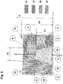
- FIG. 1 shows a fastening rail 1 for cladding or roofing over concrete components, the fastening rail 1 having a substantially C-shaped cross section, viewed orthogonally to the longitudinal extension of the fastening rail 1, with a substantially flat rail base 3 and two substantially flat rail legs 4, 5 .
- the rail base 3 has no elements protruding from the rail base 3 on the outside, relative to an interior space 6 of the fastening rail 1, and is therefore smooth.
- the rail legs 4, 5 have a plurality of recesses 7 distributed in the longitudinal direction of the fastening rail 1.
- the rail base 3 carries at least one filling element 8 on the inside, relative to the interior space 6 of the fastening rail 1, with lateral walls 9, 10 of the filling element 8 being spaced apart from the rail legs 4, 5, empty intermediate spaces 11, 12 on both sides of the Filling element 8 and a central plane 16 of the mounting rail 1, in Longitudinal direction of the fastening rail 1 and orthogonal to the rail base 3, forming towards the rail legs 4, 5.
- the filling element 8 has a height h1, measured on the inside perpendicularly from the rail base 3, and a width b1, measured perpendicularly to the height h1 and in the cross section of the fastening rail 1, the height h1 being 10% to 100% of a height h2 of the Rail leg 4, 5 is, in particular 30% to 100%, preferably 50% to 100%, most preferably 70% to 100%, including on the figure 3 is referenced. It can also be seen from this figure that in the exemplary embodiment the width b1, based on a height h, measured on the inside perpendicularly from the rail base 3, is variable, namely that it decreases as the height h increases.
- the quotient f2/f1 can be in the range from 0.1 to 0.9, in particular from 0.2 to 0.8, preferably from 0.3 to 0.8.
- a total area fa of all recesses 7 in the rail legs 4, 5 can be 10% to 90%, in particular 10% to 70%, preferably 20% to 50% of a total area of the rail legs 4, 5 fs.
- the fastening rail 1 is made of galvanized sheet steel or stainless steel sheet, with the thickness of the material in the areas of the rail base 3 and/or the rail legs 4, 5 being around 1.6 mm.
- the filling element 8 is made of a foam, for example PU foam.
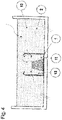
- the figures 4 and 5 shows the use of such a fastening rail 1.
- This is inserted into a non-hardened concrete material 13 with the proviso that the outside of the rail base 3 is flush with the outside of the concrete element 2 or the concrete structure after the concrete material 13 has hardened, with the non-hardened Concrete material 13 flows through the recesses 7 in the rail legs 4, 5 into the gaps 11, 12 in the fastening rail 1, with the concrete material 13 then being hardened.
- a lining or roofing 14 can be positioned over the rail floor 3, finally the lining or roofing 14 being fixed to the rail floor 3 by fixing means 15 penetrating the rail floor 3 in the area of the filling element 8.
- the fasteners 15 are self-tapping screws for sheet metal.
Landscapes
- Engineering & Computer Science (AREA)
- Architecture (AREA)
- Physics & Mathematics (AREA)
- Electromagnetism (AREA)
- Civil Engineering (AREA)
- Structural Engineering (AREA)
- Roof Covering Using Slabs Or Stiff Sheets (AREA)
- On-Site Construction Work That Accompanies The Preparation And Application Of Concrete (AREA)
Applications Claiming Priority (1)
| Application Number | Priority Date | Filing Date | Title |
|---|---|---|---|
| DE102020006992.4A DE102020006992A1 (de) | 2020-11-16 | 2020-11-16 | Befestigungsschiene |
Publications (1)
| Publication Number | Publication Date |
|---|---|
| EP4001533A1 true EP4001533A1 (fr) | 2022-05-25 |
Family
ID=78695431
Family Applications (1)
| Application Number | Title | Priority Date | Filing Date |
|---|---|---|---|
| EP21020572.0A Pending EP4001533A1 (fr) | 2020-11-16 | 2021-11-16 | Rail de fixation |
Country Status (2)
| Country | Link |
|---|---|
| EP (1) | EP4001533A1 (fr) |
| DE (1) | DE102020006992A1 (fr) |
Citations (3)
| Publication number | Priority date | Publication date | Assignee | Title |
|---|---|---|---|---|
| DE3926416A1 (de) * | 1989-08-10 | 1991-02-21 | Halfeneisen Gmbh & Co Kg | In betontraeger oder dergleichen einbettbare befestigungsschiene |
| EP0487422A1 (fr) * | 1990-11-23 | 1992-05-27 | Saret France - Ppb (S.A.) | Profilé pour la fixation d'éléments de recouvrements tels qu'une couverture sur un élément en béton tel qu'une poutre |
| EP3611307A1 (fr) | 2018-08-15 | 2020-02-19 | HALFEN GmbH | Système de rail |
Family Cites Families (3)
| Publication number | Priority date | Publication date | Assignee | Title |
|---|---|---|---|---|
| DE29610257U1 (de) | 1996-05-31 | 1996-10-02 | Deutsche Kahneisen Gesellschaft mbH, 12057 Berlin | Vorrichtung zur Herstellung einer in Beton einbettbaren Befestigungsvorrichtung, insbesondere für Trapezbleche |
| PL2918744T3 (pl) | 2014-03-13 | 2017-04-28 | Halfen Gmbh | Szyna mocująca do osadzenia w betonowym elemencie konstrukcyjnym, zwłaszcza w belce betonowej |
| DE202017000204U1 (de) | 2017-01-16 | 2017-03-30 | JORDAHL GmbH | Abdichtung Einbauteil |
-
2020
- 2020-11-16 DE DE102020006992.4A patent/DE102020006992A1/de active Pending
-
2021
- 2021-11-16 EP EP21020572.0A patent/EP4001533A1/fr active Pending
Patent Citations (3)
| Publication number | Priority date | Publication date | Assignee | Title |
|---|---|---|---|---|
| DE3926416A1 (de) * | 1989-08-10 | 1991-02-21 | Halfeneisen Gmbh & Co Kg | In betontraeger oder dergleichen einbettbare befestigungsschiene |
| EP0487422A1 (fr) * | 1990-11-23 | 1992-05-27 | Saret France - Ppb (S.A.) | Profilé pour la fixation d'éléments de recouvrements tels qu'une couverture sur un élément en béton tel qu'une poutre |
| EP3611307A1 (fr) | 2018-08-15 | 2020-02-19 | HALFEN GmbH | Système de rail |
Also Published As
| Publication number | Publication date |
|---|---|
| DE102020006992A1 (de) | 2022-05-19 |
Similar Documents
| Publication | Publication Date | Title |
|---|---|---|
| DE3588038T2 (de) | Mauerverstärkung. | |
| DE2917024A1 (de) | Vorfabrizierte wand | |
| EP1980701A1 (fr) | Profilé composite isolé thermiquement en particulier pour fenêtres, portes, façades et analogues | |
| EP4001533A1 (fr) | Rail de fixation | |
| DE3430564C2 (de) | Schalungswinkel für Decken | |
| EP4459073A1 (fr) | Renforcement pour un support de béton poreux, support de béton poreux, utilisation d'un support de béton poreux, procédé de renforcement d'un support de béton poreux et utilisation d'un renforcement | |
| DE852140C (de) | Verfahren zur Herstellung von gespannten Traegern oder gespannten Decken und danach hergestellte Traeger oder Decken | |
| AT527812B1 (de) | Verbindungselement für einen Holzbetonverbund | |
| DE9214696U1 (de) | Armierungsgewebe für Putze, Dämmsysteme o.dgl. | |
| EP3730708B1 (fr) | Élément de raccordement thermo-isolant et composant thermo-isolant | |
| DE102021103589B4 (de) | Betonbewehrungselement | |
| DE2355880A1 (de) | Blecharmiertes plattenfoermiges bauelement | |
| DE9216817U1 (de) | Maueranschlußanker | |
| EP1932978A1 (fr) | Elément d'armature pour l'absorption de forces dans des plaques de béton dans la zone d'éléments d'appui | |
| DE7524212U (de) | Befestigungsschiene für die Anbringung von Trapezblechen | |
| DE10035225C1 (de) | Höhenverstellbarer Träger für Hohlböden | |
| EP1297868B1 (fr) | Carré de ski | |
| DE102006002277A1 (de) | Befestigungsklammer | |
| AT519876A4 (de) | Vorrichtung zum kraftübertragenden Verbinden zweier Bauteile | |
| EP3907342A1 (fr) | Élément de renfort et système de renfort pour l'absorption des forces dans des panneaux en béton | |
| AT404900B (de) | Verstärkungseinlage für einen ski, insbesondere alpinski | |
| EP3130713B1 (fr) | Construction et procédé de fabrication d'une construction | |
| DE2151573C3 (de) | Deckenplatte aus Stahlbeton, insbesondere Spannbeton | |
| DE2558661A1 (de) | Betontraeger | |
| DE102004048365A1 (de) | Mast |
Legal Events
| Date | Code | Title | Description |
|---|---|---|---|
| PUAI | Public reference made under article 153(3) epc to a published international application that has entered the european phase |
Free format text: ORIGINAL CODE: 0009012 |
|
| STAA | Information on the status of an ep patent application or granted ep patent |
Free format text: STATUS: THE APPLICATION HAS BEEN PUBLISHED |
|
| AK | Designated contracting states |
Kind code of ref document: A1 Designated state(s): AL AT BE BG CH CY CZ DE DK EE ES FI FR GB GR HR HU IE IS IT LI LT LU LV MC MK MT NL NO PL PT RO RS SE SI SK SM TR |
|
| STAA | Information on the status of an ep patent application or granted ep patent |
Free format text: STATUS: REQUEST FOR EXAMINATION WAS MADE |
|
| 17P | Request for examination filed |
Effective date: 20221129 |
|
| RBV | Designated contracting states (corrected) |
Designated state(s): AL AT BE BG CH CY CZ DE DK EE ES FI FR GB GR HR HU IE IS IT LI LT LU LV MC MK MT NL NO PL PT RO RS SE SI SK SM TR |
|
| STAA | Information on the status of an ep patent application or granted ep patent |
Free format text: STATUS: EXAMINATION IS IN PROGRESS |
|
| 17Q | First examination report despatched |
Effective date: 20241210 |
|
| RAP1 | Party data changed (applicant data changed or rights of an application transferred) |
Owner name: DILER, SEREF Owner name: BARTH, MICHAEL |