EP4007619B1 - Schieberventil für transanale sp]ulungsvorrichtung - Google Patents
Schieberventil für transanale sp]ulungsvorrichtung Download PDFInfo
- Publication number
- EP4007619B1 EP4007619B1 EP20742999.4A EP20742999A EP4007619B1 EP 4007619 B1 EP4007619 B1 EP 4007619B1 EP 20742999 A EP20742999 A EP 20742999A EP 4007619 B1 EP4007619 B1 EP 4007619B1
- Authority
- EP
- European Patent Office
- Prior art keywords
- spool
- pump
- ports
- spool valve
- valve
- Prior art date
- Legal status (The legal status is an assumption and is not a legal conclusion. Google has not performed a legal analysis and makes no representation as to the accuracy of the status listed.)
- Active
Links
Images






Classifications
-
- A—HUMAN NECESSITIES
- A61—MEDICAL OR VETERINARY SCIENCE; HYGIENE
- A61M—DEVICES FOR INTRODUCING MEDIA INTO, OR ONTO, THE BODY; DEVICES FOR TRANSDUCING BODY MEDIA OR FOR TAKING MEDIA FROM THE BODY; DEVICES FOR PRODUCING OR ENDING SLEEP OR STUPOR
- A61M3/00—Medical syringes, e.g. enemata; Irrigators
- A61M3/02—Enemata; Irrigators
- A61M3/0279—Cannula; Nozzles; Tips; their connection means
- A61M3/0295—Cannula; Nozzles; Tips; their connection means with inflatable balloon
-
- A—HUMAN NECESSITIES
- A61—MEDICAL OR VETERINARY SCIENCE; HYGIENE
- A61M—DEVICES FOR INTRODUCING MEDIA INTO, OR ONTO, THE BODY; DEVICES FOR TRANSDUCING BODY MEDIA OR FOR TAKING MEDIA FROM THE BODY; DEVICES FOR PRODUCING OR ENDING SLEEP OR STUPOR
- A61M3/00—Medical syringes, e.g. enemata; Irrigators
- A61M3/02—Enemata; Irrigators
- A61M3/0233—Enemata; Irrigators characterised by liquid supply means, e.g. from pressurised reservoirs
- A61M3/0254—Enemata; Irrigators characterised by liquid supply means, e.g. from pressurised reservoirs the liquid being pumped
- A61M3/0258—Enemata; Irrigators characterised by liquid supply means, e.g. from pressurised reservoirs the liquid being pumped by means of electric pumps
-
- A—HUMAN NECESSITIES
- A61—MEDICAL OR VETERINARY SCIENCE; HYGIENE
- A61M—DEVICES FOR INTRODUCING MEDIA INTO, OR ONTO, THE BODY; DEVICES FOR TRANSDUCING BODY MEDIA OR FOR TAKING MEDIA FROM THE BODY; DEVICES FOR PRODUCING OR ENDING SLEEP OR STUPOR
- A61M3/00—Medical syringes, e.g. enemata; Irrigators
- A61M3/02—Enemata; Irrigators
- A61M3/0202—Enemata; Irrigators with electronic control means or interfaces
Definitions
- the present disclosure is directed to a spool valve for a trans-anal irrigation device.
- the disclosure provides a spool valve for use in cavity irrigation devices such as for use in an electromechanical rectal irrigation (RI) or stoma irrigation (SI) device, which may alternatively be referred to as a trans-anal irrigation (TAI) device, wherein the device has a base unit and a controller, such as is disclosed in International Patent Publication No. WO/2018/009871 .
- RI electromechanical rectal irrigation
- SI stoma irrigation
- TAI trans-anal irrigation
- SCI spinal cord injury
- other medical conditions e.g., cauda equina syndrome, multiple sclerosis (MS), spina bifida (SB), and chronic constipation
- MS multiple sclerosis
- SB spina bifida
- chronic constipation may need to avail themselves of bowel management treatments, in many cases along with a bladder management program.
- SCI users the issues of independence, dexterity, and ease of use are important needs that must be addressed by a bowel management program. Users can avail themselves of various solutions such as pharmacological (laxatives/suppository), digital stimulation, diet control and others, with the aim of having a regular bowel management routine without constipation or fecal incontinence.
- TAI provides another option for bowel management.
- RI is the delivery of irrigating liquid into the colon to flush the body's system of stool and create pseudocontinence for the end user.
- Devices currently on the market allow the user to utilize a product over the toilet, in a commode/shower chair or in a bed to introduce water into the bowel through a rectal catheter.
- the user will introduce an amount of water into the bowel (typically 500-700 mL) in order to flush out stool located in the bowel passage. It is common for the user to introduce the water, wait for a period of time and allow gravity to flush the water and stool out of the body.
- the rectal catheter may have an inflatable/deflatable balloon to assist in retention of the catheter during water introduction.
- the balloon is typically inflated by a fluid such as air or water.
- the typical RI device has an irrigation liquid reservoir and a pump base unit which contains a pump for pumping water from the reservoir through suitable tubing to the catheter.
- RI devices may use water to inflate a balloon of a rectal catheter.
- the devices may have a single-lumen tubing from a reservoir into a controller, and dual-lumen tubing from the controller to the catheter.
- One of the dual lumens may enable the rectal catheter balloon to be inflated with water and later deflated; while the second lumen may accommodates water transfer from the reservoir into the rectum.
- the device may provide that when the catheter balloon is deflated, a liquid communication channel is created so that water returning from the deflated balloon travels via the controller into the lumen toward the catheter, i.e. the water from the deflated balloon does not return to the water reservoir.
- fluid tubing sets may contain two separate lumens, one for irrigation fluid or irrigant, and one for retention balloon inflation/deflation.
- irrigation fluid or irrigant With such a device, it is desirable that neither of the tubing lumens ever communicates with the other lumen during a RI procedure, so there is no fluid communication between the lumens.
- This may be accomplished, for example, as shown in the above-identified International Patent Publication No. WO/2018/009871 , via use of a fluid control or hydraulic control circuit having a pump and at least three solenoid valves within a base.
- the solenoid valves are used to regulate the flow of water within the hydraulic control circuit and to ensure that the water in the separate tubing lumens remains independent.
- the fluid tubing set may contain three separate lumens, one for irrigant, one for waste control valve actuation, and one for retention balloon inflation/deflation. Accordingly, devices may be configured for use with different catheters, whether having a dual of triple lumen catheter.
- Devices also may be configured for use with catheters that are intended for different treatment modalities. For instance, when a balloon catheter is being used with a pump base unit and controller, the device needs to be primed, the retention balloon is inflated, the irrigant is instilled, and the retention balloon is deflated. By comparison, when a cone catheter is being used with a base unit and controller, the device needs to be primed and then the irrigant is instilled. Accordingly, there may be modalities that involve use of a cone catheter, or a balloon catheter, where the balloon catheter may be usable, for example, in a procedure conducted over a toilet or in a bed. The variety of tubing sets and modalities can present challenges for users.
- the device disclosed in the above-identified International Patent Publication No. WO/2018/009871 includes example embodiments having a pump base unit and a controller, along with a plurality of solenoid valves to regulate the flow of water within the hydraulic control circuit.
- the first example embodiment in International Patent Publication No. WO/2018/009871 uses three separate solenoid valves to control fluid flow, to perform three stages in an RI procedure.
- the three solenoid valves include a reservoir flow director valve, a pump flow director valve, and a tubing flow director valve.
- use of at least three solenoid valves may have certain disadvantages.
- the solenoid valves may be constructed using metal material for the components.
- 316L stainless steel may be used to resist corrosion due to saline solution that may flow through the solenoid valves during testing, and water that may flow through the solenoid valves during use.
- a device requiring three such stainless steel solenoid valves requires sufficient space to house the valves and adds expense and mass to the base unit.
- the present disclosure is directed to a trans-anal irrigation device that includes a spool valve for use in controlling fluid flow within the irrigation device.
- the spool valve is used to regulate the flow of fluid depending on the stage of an irrigation procedure.
- the irrigation device may be used for RI or SI, generally referred to herein as TAI.
- the spool valve includes a valve body having an elongated bore and a plurality of ports that are spaced apart and in fluid communication with the bore. The ports also are in fluid communication with different components of the irrigation device.
- the spool valve also includes a spool that slides within the bore of the valve body.
- the spool includes a plurality of lands with seals, and a plurality of grooves, which are used to open and close the various ports of the spool valve in predetermined combinations that correspond to the position of the spool within the valve body and the desired stage of a procedure.
- the spool valve is used within a hydraulic control circuit to control fluid flow within the passages of the device.
- the spool may be linearly moved by an actuator such as a linear actuator, motor or other device directly or through a drive mechanism that provides translational movement to the spool.
- the actuator is used to move the spool to at least three different positions within the valve body to control fluid flow during the various stages of operation of a TAI procedure.
- the spool valve may replace multiple solenoid valves, providing numerous advantages.
- the spool valve advantageously requires a smaller footprint for the hydraulic control circuit within the pump base unit.
- a single actuator is used to move the spool, replacing for example three solenoids that otherwise may be used for actuation of three solenoid valves that would be needed to provide a similar hydraulic control circuit.
- the spool valve components may be molded or otherwise constructed of less expensive and lighter weight materials that do not corrode.
- polymer materials may be used to construct the spool and valve body and polymer or rubber materials may be used to construct the seals disposed between the spool and bore of the valve body.
- the corrosion resistant, lighter weight spool valve having a more compact arrangement advantageously may be used within a device that includes a pump base unit, an irrigation fluid reservoir, an electronic controller, and may be in fluid communication with conduits used in RI, SI, TAI or other irrigation devices, while providing an opportunity to use a single actuator to move the spool so as to control the fluid flow during the stages of a procedure.
- Such a device provides technical solutions to multiple technical problems by providing a device with a single actuator and that is more compact, lighter weight and more corrosion resistant.
- the spool valve may be used with the controller to adjust the intended modality and to provide the proper operative procedures associated with a respective tubing set.
- the usability of a balloon catheter, for instance, to perform an RI procedure may involve the following steps: (1) prime the device (without the catheter attached); (2) attach the catheter and insert it safely inside the rectum; (3) inflate the retention balloon; (4) instil irrigation; (5) deflate the retention balloon; and (6) remove the catheter.
- the first two steps are conducted in preparation for the three stages set forth in steps 3-5. Those three stages are followed by removal of the catheter.
- the spool valve provides inlet/outlet ports for separate flow paths for communication with the tubing set.
- the spool valve effectively replaces the three solenoid valves discussed in the first example embodiment in WO/2018/009871 and provides fluid control within the hydraulic control circuit useful in performing steps 3-5 of the aforementioned procedure.
- the present disclosure provides a trans-anal irrigation device having a spool valve, the device including a pump, an irrigation fluid reservoir in fluid communication with the pump, a rectal catheter having a retention balloon and an irrigant passage through the rectal catheter, fluid tubing having at least two lumens, a first lumen providing fluid communication between the pump and the retention balloon, and a second lumen providing fluid communication between the pump and the irrigant passage.
- the device also includes a hydraulic control circuit including a spool valve having a spool that is linearly movable by an actuator.
- the spool valve includes a valve body having an elongated bore and a plurality of ports spaced apart along and in fluid communication with the elongated bore.
- the spool further includes a plurality of lands separated by a plurality of grooves, and seals extending outward from the lands and sealingly engaging the elongated bore of the valve body.
- the plurality of ports and plurality of seals and grooves are arranged for selectively directing flow alternatively from the reservoir to the retention balloon, from the reservoir to the irrigant passage, or from the retention balloon to the reservoir, based on the position of the spool within the valve body.
- the present disclosure provides a spool valve for use in a hydraulic control circuit of a trans-anal irrigation device, including a spool valve having a valve body including an elongated bore and a spool that is movable within the bore, an actuator that moves the spool relative to the bore, the spool valve further including a plurality of ports spaced apart along and in fluid communication with the bore.
- the spool further includes a plurality of lands and a plurality of seals extending radially outward from the lands and sealingly engaging the spool and the bore of the valve body, and the plurality of ports and plurality of seals and grooves are arranged for selectively directing flow through at least two passages in at least three alternative configurations based on the position of the spool within the bore of the spool valve.
- the present disclosure relates to components for use in an electromechanical body irrigation device 10, such as a rectal irrigation (RI), stoma irrigation (SI) or trans-anal irrigation (TAI) device.
- RI rectal irrigation
- SI stoma irrigation
- TAI trans-anal irrigation
- FIG. 1 A simplified view of such a system 10 is shown in FIG. 1 .
- the system 10 may include a pump base unit 12, an irrigation fluid reservoir 14, a fluid tubing 16, a tubing connector 18, a disposable rectal catheter 20 and a wireless controller 22.
- the controller 22 is shown in this example in the form of a separate controller that may communicate wirelessly with the pump base unit 12. Alternatively, a controller for the system may be directly connected to or tethered by wired connection to the pump base unit 12.
- the fluid reservoir 14 may be removable from the pump base unit 12, which in this example includes a connector 18 for establishing fluid communication with the proximal end of the fluid tubing 16.
- the fluid tubing 16 is connected at its distal end to the catheter 20.
- the catheter 20 has a retention balloon 24 that assists in sealingly holding the catheter 20 in the rectum.
- the retention balloon 24 may, for example, be attached to the exterior of the rectal catheter 20.
- the fluid tubing 16 of this example may include a retention balloon tube or lumen and an irrigant tube or lumen, such as disclosed in more detail in the first example embodiment in International Patent Publication No. WO/2018/009871 .
- FIG. 2 illustrates a generally hollow shell 100 which includes a floor 102 and a perimeter wall 104.
- the wall 104 is configured to support the base of the reservoir 14 when the reservoir is installed on the pump base unit 12.
- the wall 104 may have a handle 106 pivotably or otherwise connected to it. A user can grasp the handle 106 to carry the pump base unit 12.
- the wall 104 also has an opening 108 through it for mounting a fitting on the end of the tubing 16. The fitting allows connection of the tubing 16 and provides fluid communication between the pump and the fluid tubing 16 having a retention balloon lumen and an irrigant lumen.
- a pump 112 Inside the shell 100 there is an electric motor 110, a pump 112, one example of which may be a one-way pump, and a spool valve 113 that is movably connected to an actuator 115. It will be appreciated that the pump 112 includes at least one pump inlet and at least one pump outlet.
- the spool valve 113 effectively replaces the hydraulic control circuit that was provided by the three solenoid valves of first example embodiment in International Patent Publication No. WO/2018/009871 , allowing the pump base unit 12 of the present disclosure to otherwise operate similarly.
- the three solenoid valves being replaced include a reservoir flow director valve, a pump flow director valve, and a tubing flow director valve. The solenoid valves were normally-open, three-way valves.
- a rechargeable battery pack 120 for powering the pump 112, and internal tubing (not shown FIG. 2 for ease of viewing the other components), which provides various fluid connections and paths between the spool valve 113, the fluid reservoir 14, the pump 112 and the tubing 16.
- the fluid connections provided when using the spool valve 113 are in lieu of the connections of the internal tubing that are described in the fluid circuit diagrams shown for the first embodiment in International Patent Publication No. WO/2018/009871 .
- a power circuit board 122 and a controller printed circuit board 124 are located within the shell 100.
- a power button 126 may be located on the outside of the shell 100 to turn on and off the pump base unit 12.
- the spool valve 113 of the present example effectively replaces the aforementioned three solenoid valves in the device disclosed in Figs. 1-14 of first example embodiment in International Patent Publication No. WO/2018/009871 . It also will be appreciated that with respect to the additional embodiments in the aforementioned application, use of the spool valve 113 could be accomplished to replace solenoid valves, so as to provide similar significant advantages. Accordingly, the spool valve 113 may provide a more compact, nonmetallic, lighter weight, lower cost alternative to the use of at least three heavier and more expensive solenoid valves that may, for example, be constructed with stainless steel.
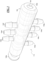
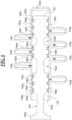
- the spool valve 113 includes a valve body 150 having an elongated bore 152 is in fluid communication with a plurality ports 154a-154g that extend outward from the bore 152 and are spaced apart along the length of the bore 152.
- the plurality of ports 154a-154g include a first port 154a associated with an outlet of the pump 112, a second port 154b associated with the reservoir 14, a third port 154c associated with an inlet of the pump 112, a fourth port 154d associated with an inlet of the pump 112, a fifth port 154e associated with a retention balloon lumen of the tubing 16, a sixth port 154f associated with an outlet of the pump 112, and a seventh port 154g associated with an irrigant lumen of the tubing 16.
- the respective ports 154a-154g may be placed in fluid communication with different components of the irrigation device, as will be further described herein.
- the spool valve 113 also includes a spool 156 that is slidably received by the bore 152 of the valve body 150.
- the valve body 150 has a proximal end opening 150a to the full diameter of the bore 152, which conveniently permits insertion of the spool 156 into the bore 152.
- the valve body 150 also has a distal end opening 150b having a smaller diameter, which provides an integrated stop for movement of the spool 156 in the distal direction, while also avoiding increased pressure or vacuum within the valve body 150 when moving the spool 156, which might otherwise restrict movement of the spool 156.
- the spool 156 includes a base 156a at its proximal end, which provides for mounting to an actuator 115.
- the spool 156 also includes a plurality of lands, shown in this example as lands 158a-158c. Each land extends radially outward from a central stem 160 of the spool, and the lands 158a-158c are separated along the length of the stem 160 by a plurality of grooves 162a, 162b.
- the lands 158a-158c include a plurality of circumferential seals 164a-164h, such as O-ring seals, which in this example are received by circumferential channels 166a-166h in the respective lands 158a-158c.
- the actuator 115 which may for example be a linear actuator, a motor with a linkage or other suitable alternative configuration, so as to provide translational or sliding movement to the spool 156 relative to the bore 152 of the valve body 150.
- the actuator 115 is controlled by the controller 22.
- the controller 22 causes the actuator 115 to slidably move the spool 156 relative to the bore 152 of the valve body 150.
- the multiple lands 158a-158c and seals 164a-164h extending over a significant length of the spool 156 provides for smooth sliding movement in the bore 152.
- the seals 164a-164h and grooves 166a-166h effectively function to provide a hydraulic control circuit that opens and closes fluid pathways between ports 154a-154g of the valve body 150.
- the spool valve 113 is used to movably arrange fluid pathways that control fluid flow in the body cavity irrigation device 10.
- the spool 156 may be moved by the actuator 115 to different positions within the valve body 150 during operation of a TAI procedure.
- the specific placement of the seals 164a-164h and grooves 162a, 162b permit the single spool valve 113 to act as if it were three separate valves.
- the spool valve 113 is in a position that corresponds to Stage 1 of a procedure.
- the spool valve 113 has been moved and now is in a position that corresponds to Stage 2 of a procedure. In this position, two ports are effectively closed by being located between seals, namely, port 154a which is associated with the outlet of the pump 112 is closed by being located between seals 164a and 164b, while port 154e which is associated with the retention balloon lumen is closed by being located between seals 164d and 164e.
- the spool valve 113 has been moved again and now is in a position that corresponds to Stage 3 of a procedure.
- three ports are effectively closed by being located between seals, namely, port 154c which is associated with the inlet of the pump 112 is closed by being located between seals 164d and 164e, while port 154f which is associated with the outlet of the pump 112 is closed by being located between seals 164f and 164g, and port 154g which is associated with the irrigant lumen is closed by being located between seals 164g and 164h.
- the spool valve 113 may replace the three solenoid valves, while providing numerous advantages.
- the spool valve 113 advantageously requires a smaller footprint for the hydraulic control circuit within the base unit 12.
- a single actuator 115 may be used to move the spool 156, replacing the three solenoids that otherwise are used for actuation of the three solenoid valves.
- the spool valve 113 components may be molded or otherwise constructed of less expensive and lighter weight materials that do not corrode, such as polymer materials for the spool 156 and valve body 150, and polymer or rubber materials for the seals 164a-164h disposed between the spool 156 and the bore 152 of the valve body 150.
- the description of the Stages and general operation of the device 10 of the present disclosure proceeds in a manner somewhat similar to that which is described and shown with respect to Figs. 1-14 of International Patent Publication No. WO/2018/009871 .
- the single spool valve 113 and single actuator 115 replace the three solenoid valves.
- the spool valve 113 uses three positions to provide a hydraulic control circuit having the fluid flows similar to those discussed in International Patent Publication No. WO/2018/009871 for Stages 1, 2 and 3 of operation of the device 10.
- the ports 154a-154g would be connected to the other components, including fluid connection of port 154a to an outlet of the pump 112; fluid connection of port 154b to the reservoir 14; fluid connection of port 154c to an inlet of the pump 112; fluid connection of port 154d to the inlet of the pump 112; fluid connection of port 154e to the retention balloon 154; fluid connection of port 154f to the outlet of the pump 112; and fluid connection of port 154g to an irrigant lumen of the tube 16.
- this disclosure provides a trans-anal irrigation device 10 having a spool valve 113, with the device 10 including a pump 112, an irrigation fluid reservoir 14 in fluid communication with the pump 112, a rectal catheter 20 having a retention balloon 24 and an irrigant passage or main passage through the rectal catheter 20.
- the device 10 includes fluid tubing having at least two lumens, a first lumen providing fluid communication between the pump 112 and the retention balloon 24, and a second lumen providing fluid communication between the pump 112 and the irrigant passage.
- the spool valve 113 is part of a hydraulic control circuit including a spool valve 113 having a spool 152 that is movable by an actuator 115.
- the spool valve 113 includes a valve body 150 having an elongated bore 152, and a plurality of ports 154a-154g spaced apart along and in fluid communication the bore 152.
- the spool 156 further includes a plurality of lands 158a-158c, separated by a plurality of grooves 166a-166h.
- the spool 156 further includes seals 164a-164h extending outward from the lands 158a-158c and sealingly engaging the elongated bore 152 of the valve body.
- the plurality of ports 154-154g and plurality of seals 164a-164h and grooves 166a-166 are arranged for selectively directing flow alternatively from the reservoir 14 to the retention balloon 24, for Stage 1 of a procedure and as shown in FIG. 6 , from the reservoir 14 to the irrigant passage in the catheter 20, for Stage 2 of a procedure and as shown in FIGS. 5 and 7 , or from the retention balloon 24 to the reservoir 14, for Stage 3 of a procedure and as shown in FIG. 8 , each of which is based on the position of the spool 156 within the valve body 150.
- a first port 154a of the plurality of ports is associated with and fluidly connected to an outlet of the pump
- a second port 154b of the plurality of ports is associated with and fluidly connected to the reservoir
- a third port 154c of the plurality of ports is associated with and fluidly connected to an inlet of the pump
- a fourth port 154d of the plurality of ports is associated with and fluidly connected to an inlet of the pump
- a fifth port 154e of the plurality of ports is associated with and fluidly connected to the retention balloon
- a sixth port 154f of the plurality of ports is associated with and fluidly connected to the outlet of the pump
- a seventh port 154g of the plurality of ports is associated with and fluidly connected to an irrigant lumen that is in fluid communication with the irrigant passage through the rectal catheter.
- the spool 156 of the spool valve 113 is movable linearly to at least three different hydraulic control positions.
- the spool valve 113 may be used to perform a method of establishing fluid paths through a spool valve 113 in a hydraulic control circuit of a trans-anal irrigation device 10, wherein the spool valve 113 comprises a valve body 150 having an elongated bore 152 and a plurality of ports 154a-154g spaced apart along and in fluid communication with the bore 152, and a spool 156 that is movable within the bore 152, and wherein the plurality of ports 154a-154g further include a first port 154a associated with a pump outlet, a second port 154b associated with a reservoir, a third port 154c associated with a pump inlet, a fourth port 154d associated with a pump inlet, a fifth port 154e associated with a retention balloon lumen, a sixth port 154f associated with a pump outlet, and a seventh port 154g associated with an irrigant lumen, with the method including at least three steps that correspond to the a
- the at least three steps include: (1) moving the spool 156 to a first position within the bore 152 of the valve body 150 wherein the second port 154b is in fluid communication with the third port 154c and the fifth port 154e is in fluid communication with the sixth port 154f, so as to establish fluid paths through the spool valve 113 from the reservoir 14 to the pump inlet and from the pump outlet to the retention balloon lumen, such as to perform Stage 1 of an anal-irrigation procedure, as shown in FIG.
- the method may further include use of an actuator 115 that may be connected to the proximal end 156a of the spool 156, and which moves the spool 156 between the first, second and third positions.
- the method also may include wherein the spool valve 113 further includes a plurality of lands 158a-158c and a plurality of seals 164a-164h extending radially outward from the lands 158a-158c and sealingly engaging the spool 156 and the bore 152 of the valve body 150.
- the plurality of ports 154a-154g and plurality of seals 164a-164h are arranged to selectively direct flow through the spool valve 113 based on the position of the spool 156.
Landscapes
- Health & Medical Sciences (AREA)
- Life Sciences & Earth Sciences (AREA)
- Anesthesiology (AREA)
- Biomedical Technology (AREA)
- Heart & Thoracic Surgery (AREA)
- Hematology (AREA)
- Engineering & Computer Science (AREA)
- Animal Behavior & Ethology (AREA)
- General Health & Medical Sciences (AREA)
- Public Health (AREA)
- Veterinary Medicine (AREA)
- External Artificial Organs (AREA)
- Infusion, Injection, And Reservoir Apparatuses (AREA)
Claims (11)
- Transanale Spülungsvorrichtung (10), die ein Schieberventil (113) aufweist, umfassend:eine Pumpe (112);einen Spülflüssigkeitsbehälter (14) in Fluidverbindung mit der Pumpe (112);einen Rektalkatheter (20), der einen Rückhalteballon (24) und einen Spülmitteldurchgang durch den Rektalkatheter (20) aufweist;Flüssigkeitsschlauchleitung (16), die mindestens zwei Lumen aufweist, wobei ein erstes Lumen Fluidverbindung zwischen der Pumpe (112) und dem Rückhalteballon (24) bereitstellt und ein zweites Lumen Fluidverbindung zwischen der Pumpe (112) und dem Spülmitteldurchgang bereitstellt;gekennzeichnet durch einen hydraulischen Steuerkreis, der ein Schieberventil (113) beinhaltet, das einen Schieber (156) aufweist, der durch einen Aktor (115) bewegbar ist;wobei das Schieberventil (113) einen Ventilkörper (150) beinhaltet, der eine längliche Bohrung (152) aufweist, in welcher der Schieber (156) durch den Aktor (115) in mindestens drei hydraulische Positionen linear bewegbar ist,und eine Vielzahl von Öffnungen (154a-154g), die entlang der länglichen Bohrung (152) beabstandet ist und in Fluidverbindung damit steht;wobei der Schieber (156) ferner eine Vielzahl von Stegen (158a-158c) umfasst, die durch eine Vielzahl von Nuten (162a, 162b) getrennt ist, wobei sich die Stege (158a-158c) von einem zentralen Schaft (160) des Schiebers (156) radial nach außen erstrecken;wobei der Schieber (156) ferner Dichtungen (164a-164h) umfasst, die sich von den Stegen (158a-158c) nach außen erstrecken und die längliche Bohrung (152) des Ventilkörpers (150) dichtend in Eingriff nehmen; unddie Vielzahl von Öffnungen (154a-154g) und die Vielzahl von Dichtungen (164a-164h) und Nuten (162a, 162b) angeordnet sind, um selektiv Fluss alternativ von dem Behälter (14) zu dem Rückhalteballon (24), von dem Behälter (14) zu dem Spülmitteldurchgang oder von dem Rückhalteballon (24) zu dem Behälter (14) zu leiten, basierend auf der Position des Schiebers (156) innerhalb des Ventilkörpers (150).
- Transanale Spülungsvorrichtung nach Anspruch 1, wobei der Rückhalteballon (24) an der Außenseite des Rektalkatheters (20) angebracht ist.
- Transanale Spülungsvorrichtung nach Anspruch 1, wobei die Stege (158a-158c) ferner Kanäle (166a-166h) umfassen, welche die Dichtungen (164a-164h) aufnehmen.
- Transanale Spülungsvorrichtung nach Anspruch 3, wobei die Dichtungen (164a-164h) als O-Ringe konstruiert sind.
- Transanale Spülungsvorrichtung nach Anspruch 1, wobei eine erste (154a) aus der Vielzahl von Öffnungen einem Auslass der Pumpe (112) zugeordnet und fluidisch damit verbunden ist, eine zweite (154b) aus der Vielzahl von Öffnungen dem Behälter (14) zugeordnet und fluidisch damit verbunden ist, eine dritte (154c) aus der Vielzahl von Öffnungen einem Einlass der Pumpe (112) zugeordnet und fluidisch damit verbunden ist, eine vierte (154d) aus der Vielzahl von Öffnungen einem Einlass der Pumpe (112) zugeordnet und fluidisch damit verbunden ist, eine fünfte (154e) aus der Vielzahl von Öffnungen dem Rückhalteballon (24) zugeordnet und fluidisch damit verbunden ist, eine sechste (154f) aus der Vielzahl von Öffnungen dem Auslass der Pumpe (112) zugeordnet und fluidisch damit verbunden ist und eine siebte (154g) aus der Vielzahl von Öffnungen einem Spülmittellumen, das in Fluidverbindung mit dem Spülmitteldurchgang durch den Rektalkatheter (20) steht, zugeordnet und fluidisch damit verbunden ist.
- Schieberventil (113) zur Verwendung in einem hydraulischen Steuerkreis einer transanalen Spülungsvorrichtung (10), umfassend:ein Schieberventil (113), gekennzeichnet durch einen Ventilkörper (150), der eine längliche Bohrung (152) undeinen Schieber (156) aufweist, der innerhalb der Bohrung (152) bewegbar ist;einen Aktor (115), der den Schieber (156) linear relativ zu der Bohrung (152) in mindestens drei hydraulische Positionen bewegt;wobei das Schieberventil (113) ferner eine Vielzahl von Öffnungen (154a-154g) umfasst, die entlang der Bohrung (152) beabstandet ist und in Fluidverbindung damit steht;wobei der Schieber (156) ferner eine Vielzahl von Stegen (158a-158c), die sich von einem zentralen Schaft (160) des Schiebers (156) radial nach außen erstreckt, und eine Vielzahl von Dichtungen (164a-164h) umfasst, die sich von den Stegen (158a-158c) radial nach außen erstreckt und den Schieber (156) und die Bohrung (152) des Ventilkörpers (150) dichtend in Eingriff nimmt; unddie Vielzahl von Öffnungen (154a-154g) und die Vielzahl von Dichtungen (164a-164h) und Nuten (162a, 162b) angeordnet sind, um selektiv Fluss durch mindestens zwei Durchgänge in mindestens drei alternativen Konfigurationen basierend auf der Position des Schiebers (156) innerhalb der Bohrung (152) des Schieberventils (113) zu leiten.
- Schieberventil nach Anspruch 6, wobei das Schieberventil (113) einen hydraulischen Steuerkreis für eine transanale Spülungsvorrichtung (10) bereitstellt, die eine Pumpe (112), einen Spülungsflüssigkeitsbehälter (14), einen Rektalkatheter (20), der einen Rückhalteballon (24) und einen Hauptdurchgang dort hindurch aufweist, beinhaltet, und wobei der hydraulische Steuerkreis Fluid in einen Schlauchleitungssatz (16) leitet, um Fluidverbindung alternativ zwischen dem Behälter (14) und dem Rückhalteballon (24), zwischen und dem Behälter (14) und dem Hauptdurchgang durch den Katheter (20) und zwischen dem Rückhalteballon (24) und dem Behälter (14) bereitzustellen.
- Schieberventil nach Anspruch 6, wobei der Schieber (156) des Schieberventils (113) mindestens drei verschiedene Steuerpositionen relativ zu der Bohrung (152) des Schieberventils (113) aufweist.
- Schieberventil nach Anspruch 6, wobei der Körper des Schieberventils (113) mindestens sieben Öffnungen (154a-154g) beinhaltet, die selektiv in Fluidverbindung mit der Bohrung (152) des Ventilkörpers (150) stehen.
- Schieberventil nach Anspruch 6, wobei der Schieber (156) und der Ventilkörper (150) aus Polymermaterialien konstruiert sind.
- Schieberventil nach Anspruch 10, wobei die Vielzahl von Dichtungen (164a-164h) aus Polymer- oder Gummimaterialien konstruiert ist.
Applications Claiming Priority (2)
| Application Number | Priority Date | Filing Date | Title |
|---|---|---|---|
| US201962882246P | 2019-08-02 | 2019-08-02 | |
| PCT/US2020/039577 WO2021025801A1 (en) | 2019-08-02 | 2020-06-25 | Spool valve for trans-anal irrigation device |
Publications (2)
| Publication Number | Publication Date |
|---|---|
| EP4007619A1 EP4007619A1 (de) | 2022-06-08 |
| EP4007619B1 true EP4007619B1 (de) | 2023-03-01 |
Family
ID=71670417
Family Applications (1)
| Application Number | Title | Priority Date | Filing Date |
|---|---|---|---|
| EP20742999.4A Active EP4007619B1 (de) | 2019-08-02 | 2020-06-25 | Schieberventil für transanale sp]ulungsvorrichtung |
Country Status (5)
| Country | Link |
|---|---|
| US (1) | US12691212B2 (de) |
| EP (1) | EP4007619B1 (de) |
| DK (1) | DK4007619T3 (de) |
| LT (1) | LT4007619T (de) |
| WO (1) | WO2021025801A1 (de) |
Family Cites Families (349)
| Publication number | Priority date | Publication date | Assignee | Title |
|---|---|---|---|---|
| US1004103A (en) | 1910-10-22 | 1911-09-26 | John P Tacey | Medical syringe. |
| US1286083A (en) | 1918-07-01 | 1918-11-26 | Sharp & Smith | Rectal speculum. |
| US1710701A (en) | 1927-11-10 | 1929-04-30 | Hertzberg Harry | Internal irrigator |
| US1853202A (en) | 1930-11-25 | 1932-04-12 | De Forest B Catlin | Internal irrigator |
| US2691373A (en) | 1951-11-15 | 1954-10-12 | Julien A Bried | Colon flushing nozzle with dissolvable tip |
| US3653377A (en) | 1970-10-01 | 1972-04-04 | Bloom Leonard | Portable power-operated douching appliance |
| US3802418A (en) | 1971-02-16 | 1974-04-09 | R Clayton | Colon catheter |
| US3731676A (en) | 1971-05-06 | 1973-05-08 | Bloom Leonard | Portable compact electric douche |
| US3794031A (en) | 1972-03-28 | 1974-02-26 | Rebold J | Electric douche |
| US3889676A (en) | 1973-03-30 | 1975-06-17 | Ezem Co | Enemata administering device |
| US3894540A (en) | 1973-10-09 | 1975-07-15 | Bonner F J Jun | Catheter |
| US3854483A (en) | 1973-10-09 | 1974-12-17 | J Powers | Urethral introduction catheter |
| US3910274A (en) | 1974-03-18 | 1975-10-07 | Hollister Inc | Stoma irrigating system |
| DE2421294C3 (de) | 1974-05-02 | 1978-06-22 | Byk Gulden Lomberg Chemische Fabrik Gmbh, 7750 Konstanz | Katheter, insbesondere Harnblasenkatheter |
| US3934722A (en) | 1974-08-26 | 1976-01-27 | American Hospital Supply Corporation | Sterile needle package |
| US4117847A (en) | 1976-02-05 | 1978-10-03 | Clayton Ralph S | Colon catheter |
| US4109659A (en) | 1976-07-19 | 1978-08-29 | Mallinckrodt, Inc. | Evagination catheters |
| AT369994B (de) | 1978-10-05 | 1983-02-25 | Illinois Tool Works | Aseptische urethralkatheterisierungseinheit |
| US4246909A (en) | 1978-10-05 | 1981-01-27 | Illinois Tool Works Inc. | Disposable urethral catheter assembly |
| CA1136943A (en) | 1978-10-20 | 1982-12-07 | Christopher A. Nowacki | Catheterization unit |
| US4386607A (en) | 1980-04-04 | 1983-06-07 | Miller Roscoe E | Enema apparata improvements relating to double contrast studies |
| EP0041487A1 (de) | 1980-05-29 | 1981-12-09 | Hans-Peter Scholander | Kathetervorrichtung |
| WO1982001403A1 (en) * | 1980-10-17 | 1982-04-29 | Goloff Charles N | Selector valve |
| US4610670A (en) | 1983-06-13 | 1986-09-09 | E. I. Du Pont De Nemours And Company | Sterile connection process, apparatus and system |
| US4604093A (en) * | 1984-06-12 | 1986-08-05 | I-Flow Corporation | Apparatus and method for administering multiple fluid infusions |
| US4682979A (en) | 1985-06-17 | 1987-07-28 | Girouard Jimmy J | Colon washing methods and apparatus |
| EP0235129A4 (de) | 1985-09-12 | 1989-08-09 | Dotolo Vincent | Verfahren, darmspekulum und kontrollvorrichtung für die darmspülung. |
| DE3843610A1 (de) | 1988-01-13 | 1989-07-27 | Stephan Dr Diekmann | Trenn- oder reaktionssaeuleneinheit |
| US5176630A (en) | 1988-09-22 | 1993-01-05 | Aegis Medical, Inc. | Rectal insertion device and control valve means therefor |
| US5019056A (en) | 1988-09-22 | 1991-05-28 | Aegis Medical, Inc. | Bowel care apparatus |
| US4890340A (en) | 1988-09-26 | 1990-01-02 | Lovitt Harold B | Self-contained hand-held bidet |
| US5097540A (en) | 1988-09-26 | 1992-03-24 | Lovitt Harold B | Self-contained hand-held bidet |
| US5149326A (en) | 1990-09-21 | 1992-09-22 | Baxter International Inc. | Adjustable catheter contamination shield |
| GB9107296D0 (en) | 1991-04-08 | 1991-05-22 | Clinical Product Dev Ltd | Surgical device |
| DE4114390A1 (de) | 1991-05-02 | 1992-11-05 | Horst Dr Med Kief | Verfahren und vorrichtung zur darmspuelung |
| US5217114A (en) | 1991-05-15 | 1993-06-08 | Applied Vascular Devices, Inc. | Catheter package |
| US5225165A (en) | 1992-05-11 | 1993-07-06 | Brandeis University | Microcentrifuge tube with upwardly projecting lid extension |
| US5413561A (en) | 1993-05-13 | 1995-05-09 | Cathco, Inc. | Guiding catheter with sealing cap system for reducing blood loss when inserting guiding catheters |
| US5405319A (en) | 1993-12-30 | 1995-04-11 | Abell; Roy | Bowel evacuation system |
| FR2717676B1 (fr) | 1994-03-28 | 1996-09-20 | Gabriel Rothan | Bague de serrage évitant l'ouverture entre la sonde urinaire et le sac collecteur collectant les urines (du malade porteur d'une sonde urinaire). |
| US5417326A (en) | 1994-03-31 | 1995-05-23 | Winer; Donald B. | Syringe container |
| DK107394A (da) | 1994-09-16 | 1996-03-17 | Uno Plast As | Anordning til måling og opsamling af legemsvæske |
| US5746721A (en) | 1995-02-15 | 1998-05-05 | C.R. Bard, Inc. | Pulsed lavage pump with integral power source and variable flow control |
| US5846216A (en) | 1995-04-06 | 1998-12-08 | G & P Technologies, Inc. | Mucous membrane infusor and method of use for dispensing medications |
| US5868265A (en) | 1995-09-16 | 1999-02-09 | Nifco, Inc. | Container cap including a primary cap and a secondary cap joined by a hinge |
| US5792108A (en) | 1995-10-23 | 1998-08-11 | C. R. Bard, Inc. | Self-priming pulsed lavage pump |
| WO1997022535A1 (en) | 1995-12-15 | 1997-06-26 | Medisystems Technology Corporation | Medical connector with integral closure |
| SE9600276D0 (sv) | 1996-01-25 | 1996-01-25 | Astra Ab | A wetting device for wetting a hydrophilic catheter and a urine collection bag incorporating said device |
| US6004305A (en) | 1996-05-03 | 1999-12-21 | Spectrum Medsystems, Inc. | Drainage catheter assembly |
| FR2750053B1 (fr) | 1996-06-21 | 1999-01-15 | Saphir Medical Sa | Generateur-distributeur bi-fonction de debit et/ou de pression |
| DK172941B1 (da) | 1996-09-18 | 1999-10-11 | Coloplast As | Urinkateterindretning |
| ES2140973T3 (es) | 1996-11-01 | 2000-03-01 | Coloplast As | Conjunto de sonda urinaria provisto de una sonda lista para el uso |
| WO1998023312A1 (en) | 1996-11-27 | 1998-06-04 | Coloplast A/S | An irrigation device |
| GB9701413D0 (en) | 1997-01-24 | 1997-03-12 | Smithkline Beecham Biolog | Novel device |
| GB9702987D0 (en) | 1997-02-13 | 1997-04-02 | Smiths Industries Ltd | Urine bag assemblies |
| GB2322079B (en) | 1997-02-13 | 2000-08-30 | Smiths Industries Plc | Urine bag assemblies |
| US6106506A (en) | 1997-03-04 | 2000-08-22 | Innovatec Medical Corp. | Method and apparatus for delivering a colonic lavage |
| US5864895A (en) | 1997-03-10 | 1999-02-02 | Toto Ltd | Handy body washer |
| SE9702748D0 (sv) | 1997-07-18 | 1997-07-18 | Astra Ab | Barrier material |
| IT1298398B1 (it) | 1997-07-24 | 2000-01-05 | Giuseppe Fuca | Apparecchio con pompa elettrica per irrigazione vaginale e/o enteroclisma |
| US6125843A (en) | 1997-09-04 | 2000-10-03 | Pincgold Llc | Liquid spray dispenser and method |
| SE9704712D0 (sv) | 1997-12-17 | 1997-12-17 | Astra Ab | Medical device |
| DK147397A (da) | 1997-12-17 | 1999-06-25 | Coloplast As | Brugsklar urinkateterindretning |
| US6053905A (en) | 1998-02-23 | 2000-04-25 | Tyco International (Us) Inc. | Self contained urethral catheter assembly with lubricating chamber |
| AU4481599A (en) | 1998-05-15 | 1999-12-06 | Great Chyren Co., Ltd. | Enema syringe, enema syringe auxiliary and injector and enema method using them |
| AU766622B2 (en) | 1998-09-23 | 2003-10-23 | Coloplast A/S | Catheter set |
| DK174621B1 (da) | 1998-11-20 | 2003-07-28 | Coloplast As | Urinkateterindretning med integreret kateterapplikator |
| SE9900465D0 (sv) | 1999-02-12 | 1999-02-12 | Astra Ab | Storage package |
| US6585721B2 (en) | 1999-05-10 | 2003-07-01 | John M Fiore | Catheter shroud with conduit, collector and improvements |
| CA2288455A1 (en) | 1999-05-12 | 2000-11-12 | G-Intek Co., Ltd. | A portable snivel inhaler |
| JP3963202B2 (ja) | 1999-07-13 | 2007-08-22 | 日本シャーウッド株式会社 | カテーテル収納スリーブ |
| HU229386B1 (en) | 1999-08-17 | 2013-11-28 | Santen Pharmaceutical Co Ltd | Eye drops container and method for manufacturing the container |
| SE9904635D0 (sv) | 1999-12-17 | 1999-12-17 | Astra Ab | Catheter wetting apparatus |
| IT1315277B1 (it) | 1999-12-30 | 2003-02-03 | Medical Internat Licensing N V | Dispositivo per lavanda rettale. |
| FI110305B (fi) | 2000-02-17 | 2002-12-31 | Instrumentarium Oyj | Sovitelma potilasvalvontamonitorin yhteydessä |
| US6569133B2 (en) | 2000-04-06 | 2003-05-27 | Uroscientific, Inc. | Urine management system for human females |
| SE516858C2 (sv) | 2000-07-25 | 2002-03-12 | Entpro Hb | Nässköljare och utloppsdel för nässköljare |
| KR100360605B1 (ko) | 2000-08-17 | 2002-11-18 | 주식회사 지인텍 | 의료기기 |
| US20020103467A1 (en) | 2001-01-31 | 2002-08-01 | Kubalak Thomas P. | Urine collection bags for urinary catheter systems |
| WO2002074363A2 (en) | 2001-03-21 | 2002-09-26 | Curatio Aps | An apparatus for flushing peripheral organs in humans or animals |
| GB0112726D0 (en) | 2001-05-25 | 2001-07-18 | Montgomery Daniel & Son Ltd | Tamper-evident device |
| GB2375964B (en) | 2001-05-31 | 2003-12-24 | Intermark Medical Innovations | A device for colonic lavage |
| US7682353B2 (en) | 2001-06-29 | 2010-03-23 | Coloplast A/S | Catheter device |
| US7311698B2 (en) | 2001-09-24 | 2007-12-25 | Coloplast A/S | Urinary catheter assembly allowing for non-contaminated insertion of the catheter into a urinary canal |
| HUP0400364A3 (en) | 2001-06-29 | 2012-05-29 | Coloplast As | A catheter assembly valve system |
| CA2452054C (en) | 2001-06-29 | 2012-05-08 | Ulf Ulmsten | A system and method for assessing urinary function |
| US6578709B1 (en) | 2001-07-19 | 2003-06-17 | Hollister Incorporated | Urinary catheter package and lubricator therefor with combined gripping and sealing means |
| US6602244B2 (en) | 2001-07-19 | 2003-08-05 | Hollister Incorporated | Lubricating and gripping device for urinary catheter package |
| DE10144892B4 (de) | 2001-09-12 | 2005-09-08 | Disetronic Licensing Ag | Mehrschichtiger Kunststoffkörper |
| DK1434611T3 (da) | 2001-10-12 | 2006-10-09 | Coloplast As | Forseglingsanordning |
| US20030073974A1 (en) | 2001-10-12 | 2003-04-17 | Falconer Malcolm Ian | Bowel irrigation probe |
| WO2003030968A1 (en) | 2001-10-12 | 2003-04-17 | Coloplast A/S | Bowel irrigation system and probe therefore |
| WO2003033398A1 (en) | 2001-10-15 | 2003-04-24 | Gerenraich Family Trust | Touch free dispenser |
| DE20117438U1 (de) | 2001-10-24 | 2002-03-21 | Maersk Medical A/S, Hårlev | Flüssigkeitsdrainagebehälter |
| DE50210940D1 (de) | 2001-11-27 | 2007-10-31 | Microcuff Gmbh | Blasenkatheter |
| US6716200B2 (en) | 2002-01-18 | 2004-04-06 | C.R. Bard, Inc. | Antimicrobial urine collection system and methods of manufacturing the same |
| US6751813B2 (en) | 2002-01-29 | 2004-06-22 | Chung Jing-Yau | Portable hygienic water jet having sanitary disposable nozzle protector on non-disposable nozzle |
| DE10213411B4 (de) | 2002-03-26 | 2006-10-26 | Hutzler, Walter | Katheter-Set |
| SE0201330D0 (sv) | 2002-04-30 | 2002-04-30 | Astra Tech Ab | Catheter assembly |
| CN102353569A (zh) | 2002-05-13 | 2012-02-15 | 贝克顿·迪金森公司 | 蛋白酶抑制剂样品采集系统 |
| WO2004006993A1 (en) | 2002-07-12 | 2004-01-22 | Coloplast A/S | Irrigation system |
| SE522982C2 (sv) | 2002-07-29 | 2004-03-23 | Roger Joensson | Kroppsfixerad anordning för uppsamling av okontaminerat urinprov från mindre barn |
| US7120487B2 (en) | 2002-08-08 | 2006-10-10 | Nelson David A | Catheter system and method for administering regional anesthesia to a patient |
| US7147627B2 (en) | 2002-08-21 | 2006-12-12 | Hollister Incorporated | Bowel management system |
| ITGE20020079A1 (it) | 2002-09-04 | 2004-03-05 | Cecco Corrado Di | Dispositivo per la pulizia del canale auricolare. |
| US20060212020A1 (en) | 2002-10-10 | 2006-09-21 | Lynne Rainen | Sample collection system with caspase inhibitor |
| US20040074794A1 (en) | 2002-10-18 | 2004-04-22 | Conway Anthony J. | Catheter wetting system and method |
| ES2271639T3 (es) | 2002-10-23 | 2007-04-16 | Coloplast A/S | Dispositivo de acoplamiento. |
| WO2004043816A1 (en) | 2002-11-13 | 2004-05-27 | Hoffmann Neopac Ag | Tamper evident tube closure with twist-away centring |
| EP1567219A1 (de) | 2002-11-29 | 2005-08-31 | Coloplast A/S | Katheter |
| NL1022161C2 (nl) | 2002-12-13 | 2004-06-18 | Karel Hero Mulder | Urologisch instrument voor het beoordelen van een urinestroom. |
| US7147468B2 (en) | 2002-12-31 | 2006-12-12 | Water Pik, Inc. | Hand held oral irrigator |
| DE602004025804D1 (de) | 2003-01-27 | 2010-04-15 | Mitsui Chemicals Inc | Propylenpolymerzusammensetzung und Verwendung davon |
| EP1597167B2 (de) | 2003-02-07 | 2013-08-21 | Coloplast A/S | Behälter |
| JP2004305466A (ja) | 2003-04-08 | 2004-11-04 | Nipro Corp | 医療用コネクターセット及びそれを用いた留置用カテーテルセット |
| EP1615690B1 (de) | 2003-04-11 | 2011-06-29 | Coloplast A/S | Katheteranordnung mit kathetergriff und behälter |
| EP1638856A1 (de) | 2003-04-30 | 2006-03-29 | Ranbaxy Laboratories, Ltd. | Behälter mit klappdeckel mit eingebautem trockenmittel |
| US6822253B1 (en) | 2003-05-09 | 2004-11-23 | Biodex Medical Systems, Inc. | Radiopharmaceutical shipping pig with encapsulated lead shielding |
| WO2004103153A2 (en) | 2003-05-16 | 2004-12-02 | Cawood Family Limited Partnership | Urine pump for condom catheters and method for using |
| US20040260152A1 (en) | 2003-06-20 | 2004-12-23 | Jeanene Sant | Speculum assembly |
| DE10329128B4 (de) | 2003-06-27 | 2005-04-28 | Ruesch Willy Gmbh | Blasenkatheter-Set |
| GB2403151A (en) | 2003-06-27 | 2004-12-29 | Intermark Medical Innovations | A device for rectal lavage |
| DE10329126B4 (de) | 2003-06-27 | 2006-11-09 | Willy Rüsch GmbH | Katheterapplikationssystem |
| MY142781A (en) | 2003-06-28 | 2010-12-31 | Peter A K Yong | Dual-chamber liquid receiving and containing device |
| ES2824624T3 (es) | 2003-08-08 | 2021-05-12 | Hollister Inc | Hidratación por vapor de un catéter hidrófilo en un envase |
| DE60326495D1 (de) | 2003-08-21 | 2009-04-16 | Tsukada Medical Res Co Ltd | Intermittierendes selbsthaltendes harnröhren-katheterset |
| US8016816B2 (en) | 2003-09-09 | 2011-09-13 | Convatec Technologies Inc. | Fecal management appliance and method and apparatus for introducing same |
| US20050070933A1 (en) | 2003-09-26 | 2005-03-31 | Leiboff Arnold R. | Apparatus and method for intestinal irrigation |
| AU2003289579A1 (en) * | 2003-09-29 | 2005-04-14 | Aser Tech Co., Ltd. | Slide spool-type valve |
| WO2005032617A2 (en) | 2003-10-08 | 2005-04-14 | Roy Abell | Method for delivering a colonic lavage |
| DE20317135U1 (de) | 2003-11-07 | 2004-01-15 | Grundke, Reinhold | Beinbeutel |
| JP4833200B2 (ja) | 2004-05-25 | 2011-12-07 | イノヴェイティブ ジネコロジカル ソリューションズ インコーポレイテッド | 医療器具 |
| US8172101B2 (en) | 2004-07-13 | 2012-05-08 | Becton, Dickinson And Company | Flip top cap with contamination protection |
| CN101803968B (zh) | 2004-07-14 | 2012-10-03 | 科洛普拉斯特公司 | 紧缩袋 |
| WO2006010556A1 (de) | 2004-07-23 | 2006-02-02 | Microcuff Gmbh | Vorrichtung zum verschliessen eines natürlichen oder künstlichen darmausgangs |
| US7717284B2 (en) | 2004-07-27 | 2010-05-18 | Becton, Dickinson And Company | Flip top cap |
| US20060025728A1 (en) | 2004-07-30 | 2006-02-02 | Leiboff Arnold R | Device and method for colonic lavage |
| US20060025729A1 (en) | 2004-07-30 | 2006-02-02 | Leiboff Arnold R | Transanal colorectal irrigators |
| US7789873B2 (en) | 2004-08-02 | 2010-09-07 | Coloplast A/S | Urinary catheter assembly |
| WO2006024205A1 (en) | 2004-08-30 | 2006-03-09 | Shenzhen Mermaid Industry Development Ltd. | Enema apparatus |
| DE102004043434B3 (de) | 2004-09-06 | 2006-05-18 | Klaus Schmitt Beteiligungsgesellschaft Mbh | Urinbeutel |
| US7896857B2 (en) | 2004-10-12 | 2011-03-01 | Bioderm, Inc. | Urine collection assembly |
| WO2006044621A2 (en) | 2004-10-15 | 2006-04-27 | The Regents Of The University Of California | Improved drainage system |
| PT2407202E (pt) | 2004-10-25 | 2015-01-02 | Coloplast As | Cateter telescópico para indivíduos do sexo masculino |
| KR100597217B1 (ko) | 2004-11-23 | 2006-07-06 | 조영국 | 첨가제 첨가 가능한 위조방지 위생이중캡 |
| US20060180585A1 (en) | 2004-12-29 | 2006-08-17 | Rubbermaid Incorporated | Twist up spout for beverage container |
| TWM269893U (en) | 2005-01-07 | 2005-07-11 | Lung-Sheng Tsai | Domestic water-therapeutic apparatus for large intestine |
| US7571804B2 (en) | 2005-03-03 | 2009-08-11 | Coloplast A/S | Package for a medical device |
| US8956333B2 (en) | 2005-04-22 | 2015-02-17 | Alternamedics Llc | Medication delivery device |
| WO2006121183A1 (en) | 2005-05-11 | 2006-11-16 | Showa Denko K.K. | Elastomer composition |
| DE202005008071U1 (de) | 2005-05-23 | 2005-07-21 | Grundke, Reinhold | Mobile Harnauffangtasche |
| JP5128471B2 (ja) | 2005-06-13 | 2013-01-23 | スミス アンド ネフュー インコーポレーテッド | 外科手術用流体の管理 |
| DE202005009946U1 (de) | 2005-06-24 | 2005-09-15 | Medical Service Gmbh | Kathetersystem |
| CA2614241C (en) | 2005-07-01 | 2013-11-12 | C.R. Bard, Inc. | Indwelling urinary drainage catheter |
| CA2614366C (en) | 2005-07-05 | 2013-10-15 | C.R. Bard, Inc. | Multi-functional and modular urine collection system |
| US20070073216A1 (en) | 2005-07-07 | 2007-03-29 | The Pulsed Enema Company | Method and apparatus for delivering a colonic lavage |
| US7546931B2 (en) | 2005-07-08 | 2009-06-16 | Becton, Dickinson And Company | Flip top cap |
| US7118050B1 (en) | 2005-07-20 | 2006-10-10 | Chiang-Pei Chen | Sprayer with changeable volume |
| US8591457B2 (en) | 2005-08-10 | 2013-11-26 | Alza Corporation | Method for making a needle-free jet injection drug delivery device |
| WO2007022223A2 (en) | 2005-08-17 | 2007-02-22 | Colorado Catheter Company, Inc. | Catheterization assembly |
| WO2007038988A1 (en) | 2005-10-03 | 2007-04-12 | Coloplast A/S | Male incontinence product and package therefor |
| US8328792B2 (en) | 2005-10-27 | 2012-12-11 | C. R. Bard, Inc. | Enhanced pre-wetted intermittent catheter with lubricious coating |
| US7625355B2 (en) | 2005-11-17 | 2009-12-01 | Chun Ho Yu | Easy drainage catheter assembly |
| KR200411940Y1 (ko) | 2006-01-02 | 2006-03-21 | 유병언 | 온도조절이 가능한 포터블형 세척기의 접이식 물통 |
| SE529135C2 (sv) | 2006-01-10 | 2007-05-08 | Cimatex Ab | Behållare för en kateter |
| ATE454181T1 (de) | 2006-01-20 | 2010-01-15 | Coloplast As | Behälter für medizinische vorrichtungen |
| US20070213668A1 (en) | 2006-03-07 | 2007-09-13 | Aaron Spitz | Foot Operated Irrigation Control Apparatus for Medical Procedures |
| US8317775B2 (en) | 2006-03-10 | 2012-11-27 | Adapta Medical, Inc. | Urinary catheterization assembly with vented sheath |
| US7662146B2 (en) | 2006-03-10 | 2010-02-16 | Colorado Catheter Company, Inc. | Indwelling urinary catheterization assembly |
| WO2007106356A2 (en) | 2006-03-10 | 2007-09-20 | Ebrahim Versi | Self-catheterization device to administer compounds to the bladder |
| WO2007111894A2 (en) | 2006-03-22 | 2007-10-04 | Otto Edgar A | Urine collection bag |
| US7967744B2 (en) | 2006-04-10 | 2011-06-28 | U.S. Endoscopy Group, Inc. | Biopsy inlet valve |
| US20070244468A1 (en) | 2006-04-13 | 2007-10-18 | Nick Kostandaras | Safety Device for Use with Catheters |
| US8434639B2 (en) | 2006-06-19 | 2013-05-07 | C & N Packaging, Inc. | One piece, push button, flip top closure |
| EP1872814A1 (de) | 2006-06-27 | 2008-01-02 | Debiotech S.A. | Medizinische Vorrichtung zur Durchführung einer Flüssigkeitsbehandlung |
| ATE454914T1 (de) | 2006-07-11 | 2010-01-15 | Astra Tech Ab | Harnkatheter mit rückschlagventil |
| US8734399B2 (en) | 2006-07-14 | 2014-05-27 | Nelson Medical Devices, Llc | Self cleaning catheter and methods of use thereof |
| AU2007276247A1 (en) | 2006-07-18 | 2008-01-24 | Coloplast A/S | A packaging for a medical article and a catheter in such a packaging |
| US20080065001A1 (en) | 2006-08-23 | 2008-03-13 | Dinucci Kent | Portable debridement and irrigation device |
| EP1897579B2 (de) | 2006-09-06 | 2013-10-16 | Medical Service GmbH | Katheter-Set |
| EP1897580B1 (de) | 2006-09-06 | 2016-07-06 | Medical Service GmbH | Katheter-Set |
| DE202006013663U1 (de) | 2006-09-06 | 2006-11-02 | Medical Service Gmbh | Katheter-Set |
| WO2008030999A2 (en) | 2006-09-07 | 2008-03-13 | Sklar, Warren, A. | Safety catheter introducer |
| US20080125750A1 (en) | 2006-09-27 | 2008-05-29 | Henning Arthur Gaissert | Medical catheter removal |
| MX2009003994A (es) | 2006-10-17 | 2009-05-25 | Bard Inc C R | Sistema de manejo de residuos. |
| JP2010527636A (ja) | 2006-11-06 | 2010-08-19 | アードバーク メディカル, エルエルシー | 洗浄と吸引の装置および方法 |
| US8177765B2 (en) | 2007-01-12 | 2012-05-15 | Adapta Medical, Inc. | Collection devices for catheter assemblies |
| EP1946786A1 (de) | 2007-01-19 | 2008-07-23 | Coloplast A/S | Spülsystem mit Pumpe |
| EP1946785A1 (de) | 2007-01-19 | 2008-07-23 | Coloplast A/S | Bewässerungssystem |
| DE08702680T1 (de) | 2007-01-23 | 2010-08-26 | Association For Public Health Services | Flüssigkeitstestanordnung |
| BRPI0808878B8 (pt) | 2007-03-14 | 2021-06-22 | Coloplast As | dispositivo de mudança e um sistema de iirrigação compreendendo o dispositivo |
| EP1977778A1 (de) | 2007-04-06 | 2008-10-08 | Markos Mefar S.P.A. | Elektronischer Vernebler zum Auswaschen der Nasennebenhöhlen eines Benutzers |
| DE102007018277A1 (de) | 2007-04-18 | 2008-10-30 | Medical Service Gmbh | Katheter-Set |
| US8512312B2 (en) | 2007-05-01 | 2013-08-20 | Medtronic, Inc. | Offset catheter connector, system and method |
| EP2148714B1 (de) | 2007-05-16 | 2021-03-03 | Coloplast A/S | Kupplungsanordnung für ein ausziehbares gerät |
| US20100211050A1 (en) | 2007-05-16 | 2010-08-19 | Coloplast A/S | Coupling arrangement for a telescopic device |
| TW200848010A (en) | 2007-06-15 | 2008-12-16 | Avita Corp | Nose vacuum device |
| EP2164554A1 (de) | 2007-07-13 | 2010-03-24 | Coloplast A/S | Spitze für eine einsetzvorrichtung |
| EP2180914A1 (de) | 2007-07-16 | 2010-05-05 | Med-I-Dynamix Fluid Monitoring Ltd. | Systeme und verfahren zur entfernung von urin |
| WO2009015152A1 (en) | 2007-07-22 | 2009-01-29 | C.R. Bard, Inc. | Waste management system |
| US20090036874A1 (en) | 2007-07-31 | 2009-02-05 | Horowitz Patricia | Disposable covering device and method |
| US20090076441A1 (en) | 2007-08-15 | 2009-03-19 | Eric Sebban | Aspirator assembly |
| US20090054876A1 (en) | 2007-08-24 | 2009-02-26 | German Borodulin | Compact ready-to-use urethral catheter assembly with means for injecting therapeutic liquid into urethral channel |
| EP2465550A1 (de) | 2007-10-03 | 2012-06-20 | Astra Tech AB | Katheteraufnahme mit einer antimikrobiellen Verbindung |
| NL1034562C2 (nl) | 2007-10-22 | 2009-04-23 | Iq & Invest N V | Urinekatheter, werkwijze en inbrenginrichting. |
| CN101842125B (zh) | 2007-10-30 | 2012-07-04 | 医研比赫国际股份公司 | 肠灌洗装置及其使用方法 |
| ES2604253T3 (es) | 2007-11-19 | 2017-03-06 | Hollister Incorporated | Conjunto de catéter hidratado al vapor y método de fabricación del mismo |
| TW200927204A (en) | 2007-11-23 | 2009-07-01 | Lameplast Spa | Cannula for dispensing fluid products, particularly for rectal applications (1) |
| WO2009080051A1 (en) | 2007-12-21 | 2009-07-02 | Coloplast A/S | Pressure-controlled balloon catheter |
| DK2072075T3 (da) | 2007-12-21 | 2010-11-15 | Astra Tech Ab | Kateterindretning med en foldet urinopsamlingspose |
| US20090166361A1 (en) | 2007-12-29 | 2009-07-02 | Airsec | Two-part, flip top, snap cap for vials |
| ITTO20080067A1 (it) | 2008-01-31 | 2009-08-01 | Alplast Spa | Capsula di sicurezza per un contenitore, in particolare per una bottiglia per liquidi |
| EP2106821B1 (de) | 2008-03-31 | 2019-04-17 | Dentsply IH AB | Katheteranordnung mit einem rohrförmigen Mittel mit gefalteten Bereichen und Verfahren zur Aktivierung und Herstellung davon |
| ITBS20080081A1 (it) | 2008-04-15 | 2009-10-16 | Flaem Nuova Spa | Dispositivo per il lavaggio delle cavita' nasali con pompa incorporata |
| NZ629430A (en) | 2008-05-01 | 2016-07-29 | Convatec Technologies Inc | Rectal drain appliance |
| US20100130949A1 (en) | 2008-05-16 | 2010-05-27 | Garcia Maurice M | Catheter drainage system |
| WO2009144028A1 (de) | 2008-05-29 | 2009-12-03 | Advanced Medical Balloons Gmbh | Vorrichtung zur stuhldrainage |
| WO2009153973A1 (ja) | 2008-06-19 | 2009-12-23 | 学校法人産業医科大学 | 直腸カテーテル及び注腸薬浸透促進システム |
| WO2010006620A1 (en) | 2008-07-16 | 2010-01-21 | Coloplast A/S | A package for a urinary catheter |
| CA2738709C (en) | 2008-09-29 | 2014-05-27 | Vifor (International) Ag | Cap assembly and production method |
| CN102186392A (zh) | 2008-10-20 | 2011-09-14 | 朴本元 | 无需将喷嘴插入肛门的家用手持结肠冲洗器 |
| US20110224653A1 (en) | 2008-11-14 | 2011-09-15 | Coloplast A/S | Coupling arrangement for a telescopic device |
| EP2349375A4 (de) | 2008-11-17 | 2017-05-10 | C.R.Bard, Inc. | Müllentsorgungssystem |
| EP2373234A1 (de) | 2008-12-16 | 2011-10-12 | Aardvark Medical, Inc. | Verfahren und system zur freisetzung von flüssigkeiten, aerosolen und schallenergie auf gewebeoberflächen, in kavitäten und verstopften kanälen wie etwa intranasale ostia |
| CA2754608C (en) | 2009-03-25 | 2021-06-01 | Deka Products Limited Partnership | Infusion pump methods and systems |
| CN102405072B (zh) | 2009-04-08 | 2013-11-27 | 科洛普拉斯特公司 | 具有整合的控制单元的泵 |
| WO2010115430A1 (en) | 2009-04-08 | 2010-10-14 | Coloplast A/S | Lever pump for use in anal irrigation |
| EP2424590B1 (de) | 2009-04-27 | 2021-07-07 | Aardvark Medical, Inc. | Bewässerungs- und absaugungsvorrichtungen |
| BRPI1010832B1 (pt) | 2009-05-12 | 2020-01-21 | Coloplast As | saco e kit de partes para coleta de urina |
| MX345403B (es) | 2009-05-13 | 2017-01-30 | Sio2 Medical Products Inc | Revestimiento por pecvd utilizando un precursor organosilícico. |
| US8137337B2 (en) | 2009-06-24 | 2012-03-20 | Hakky Said I | Indwelling urinary catheter with self-retaining mechanism |
| JP2012533399A (ja) | 2009-07-22 | 2012-12-27 | シー・アール・バード・インコーポレーテッド | あらかじめ濡らした親水性・断続使用カテーテル、及びその使用法 |
| EP2459264B1 (de) | 2009-07-29 | 2013-12-25 | C.R. Bard Inc. | Katheter mit verbesserter Drainage |
| FR2948574B1 (fr) | 2009-07-31 | 2014-08-15 | Braun Medical Sas | Sonde pour irrigation transanale |
| WO2011019359A1 (en) | 2009-08-13 | 2011-02-17 | C. R. Bard, Inc. | Catheter having internal hydrating fluid storage and/or catheter package using the same and method of making and/or using the same |
| WO2011018092A1 (en) | 2009-08-14 | 2011-02-17 | Coloplast A/S | An anal probe and a complementary connector |
| CA2770233C (en) | 2009-08-26 | 2017-05-02 | Mbh-International A/S | An irrigation device and method of using the device |
| DK2674185T3 (en) | 2009-09-04 | 2017-02-13 | Dentsply Ih Ab | CATS WITH CUSTOMIZABLE CONNECTOR |
| US8500684B2 (en) | 2009-09-18 | 2013-08-06 | Bruce A. Gardner | Balloon catheter |
| US8728058B2 (en) | 2009-11-26 | 2014-05-20 | Coloplast A/S | Telescopic device |
| US9061096B2 (en) | 2009-12-16 | 2015-06-23 | Water Pik, Inc. | Powered irrigator for sinus cavity rinse |
| WO2011075581A1 (en) | 2009-12-16 | 2011-06-23 | Water Pik, Inc. | Powered irrigator for sinus cavity rinse |
| BR112012014474B1 (pt) | 2009-12-21 | 2020-01-21 | Coloplast As | jogo de cateter para uso urinário |
| DK3078393T3 (en) | 2009-12-23 | 2018-01-02 | Bard Inc C R | Catheter device / package using a hydrating / hydrogel lining |
| MX2012009389A (es) * | 2010-02-11 | 2012-12-17 | Hollister Inc | Manguito de inflado con preventor de sobrepresión transitorio-resistente. |
| CA2779692A1 (en) | 2010-02-26 | 2011-09-01 | Byung Eun Yoo | Portable enema device |
| WO2011109393A1 (en) | 2010-03-04 | 2011-09-09 | C.R. Bard, Inc. | Catheter assembly/package utilizing a hydrating/hydrogel sleeve and a foil outer layer and method of making and using the same |
| KR101168229B1 (ko) | 2010-03-09 | 2012-07-30 | 대한약품공업 주식회사 | 수액백용 포트 |
| DE202010007433U1 (de) | 2010-04-20 | 2011-06-01 | Klosterfrau Berlin GmbH, 12277 | Gel, insbesondere Gleitgel |
| DE202010006267U1 (de) | 2010-04-23 | 2010-11-11 | Anbatec Gmbh | Produkt mit einer antimikrobiell wirksamen Oberfläche |
| AU2011248886B2 (en) | 2010-05-03 | 2016-05-12 | Convatec Technologies Inc. | Drainage appliance for body waste |
| DK2389972T3 (da) | 2010-05-25 | 2014-03-31 | Dentsply Ih Ab | Kateterenhed, der omfatter en beholder rummende et kateter og en pose med befugtningsvæske |
| WO2011151630A1 (en) | 2010-06-04 | 2011-12-08 | Threadless Closures Limited | Closure for a container |
| GB2482000A (en) | 2010-07-14 | 2012-01-18 | Threadless Closures Ltd | Closure having Seal and Inner and Outer Components |
| FR2961886B1 (fr) | 2010-06-23 | 2012-08-10 | Braun Medical Sas | Systeme de raccord a deux pieces destine a un tuyau a deux lumieres |
| EP2590705A4 (de) | 2010-07-09 | 2018-01-10 | The Regents of The University of California | Sicherheitsblasenkatheter |
| US9480833B2 (en) | 2010-07-15 | 2016-11-01 | Becton, Dickinson And Company | Antimicrobial IV access cap |
| KR101058241B1 (ko) | 2010-07-23 | 2011-08-22 | 정경진 | 포리카테타 삽입을 위한 조립체 |
| EP2598195B1 (de) | 2010-07-26 | 2015-12-30 | Steerable Instruments B.V.B.A. | Kapillarrohranordnung |
| US20130218106A1 (en) | 2010-07-30 | 2013-08-22 | C. R. Bard, Inc. | Automated Method of Pooling Elimination with a Biological Fluid Collection System |
| EP2600914B1 (de) | 2010-08-05 | 2015-08-05 | Coloplast A/S | Wasserdampfsperrschlauch für verpackungszwecke |
| BR112013001758A2 (pt) | 2010-08-05 | 2016-05-31 | Coloplast As | acondicionamento de cateter,e , conjunto de acondicionamento de cateter |
| US8579115B2 (en) | 2010-08-26 | 2013-11-12 | Combat Medical Systems, Llc | Protective containers for medical devices and methods of use |
| KR200465659Y1 (ko) | 2010-09-14 | 2013-03-05 | (주)연우 | 링 플립-탑 튜브용기 |
| US8448798B2 (en) | 2010-10-05 | 2013-05-28 | Weatherchem Corporation | Dispensing closure with pliable sealing surface |
| EP2452706A3 (de) | 2010-10-26 | 2012-06-27 | Reinhard Schlenzka | Darmrohr- Anordnung zur Applikation einer Flüssigkeit |
| DE102010060168A1 (de) | 2010-10-26 | 2012-04-26 | Reinhard Schlenzka | Darmrohr-Anordnung zur Durchführung von Darmspülungen |
| DK2450076T3 (en) | 2010-11-04 | 2017-12-04 | Curan Medical B V | Package with catheter |
| CA2817010C (en) | 2010-11-04 | 2019-01-22 | Curan Medical Bv | Package with catheter |
| PL2468319T3 (pl) | 2010-11-29 | 2017-05-31 | Eurochit Danuta Kruszewska | Nowy nanoprodukt przydatny w zabiegach profilaktycznych, diagnostycznych oraz leczniczych w medycynie ludzkiej i w weterynarii |
| US9205222B2 (en) | 2010-12-17 | 2015-12-08 | Coloplast A/S | Catheter assembly |
| EP2468346B1 (de) | 2010-12-22 | 2020-11-04 | Dentsply IH AB | Katheteranordnung und Verfahren und System zur Herstellung der Anordnung |
| EP2468326A1 (de) | 2010-12-27 | 2012-06-27 | Iniziativa Centro Sud S.r.l. | Sanitäre Vorrichtung zur Darmreinigung |
| GB2500354B (en) | 2011-02-04 | 2016-05-18 | Lifetime Brands Inc | Expanding sealing locking systems and methods |
| GB201102731D0 (en) | 2011-02-16 | 2011-03-30 | Feneley Roger C L | catheters |
| ITBO20110116A1 (it) | 2011-03-10 | 2012-09-11 | Martino Renato Di | Apparecchiatura per l'esecuzione di irrigazioni transanali |
| EP2686054B2 (de) | 2011-03-18 | 2022-10-12 | Coloplast A/S | Katheteranordnung |
| WO2012134804A1 (en) | 2011-03-25 | 2012-10-04 | Hollister Incorporated | Urine collection assembly and method |
| US8728169B2 (en) | 2011-05-11 | 2014-05-20 | Boston Scientific Scimed, Inc. | Medical apparatuses for delivery of urologically beneficial agents |
| DK2709704T3 (en) | 2011-05-17 | 2017-03-13 | Joanneum Res Forschungsgmbh | Catheter with a healing dummy |
| US8556884B2 (en) | 2011-05-31 | 2013-10-15 | Compactcath, Inc. | Compact catheter assembly |
| SE536277C2 (sv) | 2011-06-01 | 2013-07-30 | Catheasy Vaesteraas Ab | Spolningsanordning och kit innefattande en spolningsanordning |
| WO2012164559A1 (en) | 2011-06-02 | 2012-12-06 | Torus Medical Ltd | Method and apparatus for cleansing a colon of a patient |
| DE102012008663A1 (de) | 2011-08-20 | 2013-02-21 | Advanced Medical Balloons Gmbh | Darmrohr |
| US20140296831A1 (en) | 2011-08-20 | 2014-10-02 | Fred Göbel | Trans-anal inflow catheter and method for intermittently triggering a reflex-coordinated defecation |
| WO2013029622A1 (en) | 2011-08-29 | 2013-03-07 | Coloplast A/S | An assembly for urinary drainage |
| US9585784B2 (en) | 2011-08-29 | 2017-03-07 | Coloplast A/S | Catheter activation by handle removal |
| RU2607182C2 (ru) | 2011-08-29 | 2017-01-10 | Колопласт А/С | Комплект мочевого катетера |
| DE202011107025U1 (de) | 2011-10-21 | 2013-01-25 | Medical Service Gmbh | Katheter-Set |
| DE202011107059U1 (de) | 2011-10-21 | 2013-01-25 | Medical Service Gmbh | Katheterset mit Einführhilfe |
| EP2776087B1 (de) | 2011-11-08 | 2019-02-27 | Hollister Incorporated | Kit für transanale bewässerung |
| BR112014011917B1 (pt) | 2011-11-25 | 2020-12-01 | Coloplast A/S | montagem de cateter urinário |
| GB2496900A (en) | 2011-11-25 | 2013-05-29 | Welland Medical Ltd | Pneumatic irrigation system |
| US9889272B2 (en) | 2011-12-09 | 2018-02-13 | Coloplast A/S | Liquid stop |
| US9861795B2 (en) | 2011-12-16 | 2018-01-09 | Musc Foundation For Research Development | Double balloon catheter |
| EP3572114A1 (de) | 2011-12-27 | 2019-11-27 | Dentsply IH AB | Vorübergehend faltbare katheteranordnung |
| WO2013105091A1 (en) | 2012-01-11 | 2013-07-18 | Uc-Care Ltd. | Catheterization apparatus and methods thereof |
| US8936562B2 (en) | 2012-03-08 | 2015-01-20 | Ez Ears, Llc | EZ ears |
| US20130245380A1 (en) | 2012-03-15 | 2013-09-19 | Delmar Vogel | Hydro-Colonoscopy Combination System |
| EP2841143B1 (de) | 2012-04-27 | 2016-06-01 | Covidien LP | Flüssigkeitsabgabevorrichtung mit verbinder und einem faltbaren reservoir |
| US20130326803A1 (en) | 2012-06-06 | 2013-12-12 | Kadi Maleki | Personal Cleansing Apparatus |
| HUE032649T2 (en) | 2012-06-07 | 2017-10-30 | Dentsply Ih Ab | Double pump irrigation system |
| EP2671601B1 (de) | 2012-06-07 | 2016-03-16 | Dentsply IH AB | Irrigationssystem mit vorbeladenem Irrigationsflüssigkeitsbehälter |
| EP2679259B1 (de) | 2012-06-29 | 2017-04-19 | Dentsply IH AB | Motorisiertes Bewässerungssystem |
| EP2682069A1 (de) | 2012-07-05 | 2014-01-08 | Unomedical A/S | Medizinisches Verpackungssystem |
| EP3184132B1 (de) | 2012-08-30 | 2020-10-07 | Advanced Medical Balloons GmbH | Folienverschweisstes behältnis zur unterbringung einer vorrichtung zur einbringung eines irrigationsmediums und/oder zur triggerung eines defäkationsreflexes im rahmen einer wegwerfeinmalanwendung |
| DK2908897T3 (da) | 2012-10-19 | 2023-09-11 | Hollister Inc | Intermitterende urinkatetersamling |
| GB2507312B (en) | 2012-10-25 | 2015-03-11 | Tristel Plc | Hand-held pump apparatus |
| DK177651B1 (en) | 2012-10-26 | 2014-02-03 | Mbh Internat A S | Method of preparing a ready-to-use urinary catheter and a catheter assembly for use in said method |
| CA2891118C (en) | 2012-11-12 | 2017-07-04 | Hollister Incorporated | Intermittent catheter assembly and kit |
| CA2891117C (en) | 2012-11-12 | 2017-05-23 | Hollister Incorporated | Vapor hydration of medical device within package |
| US9872969B2 (en) | 2012-11-20 | 2018-01-23 | Rochester Medical Corporation, a subsidiary of C.R. Bard, Inc. | Catheter in bag without additional packaging |
| US10137279B2 (en) | 2012-11-29 | 2018-11-27 | William Beaumont Hospital | Catheter guide and method for utilizing the same |
| EP3187208B1 (de) | 2012-12-06 | 2018-09-05 | Stryker Corporation | Spülungseinheit mit in den leerraum eines an der spülungseinheit befestigen saugrohrs reichende internen rippen |
| EP2928535A1 (de) | 2012-12-10 | 2015-10-14 | Hollister Incorporated | Gebrauchsfertige medizinische vorrichtung mit sofortiger antimikrobieller wirkung |
| US9296508B2 (en) | 2012-12-13 | 2016-03-29 | Gojo Industries, Inc. | Collapsible containers and refill units |
| DE102013014483A1 (de) | 2012-12-20 | 2014-06-26 | Creative Balloons Maschinenbau Gmbh & Co. Kg | Blasenkatheter |
| JP2016508810A (ja) * | 2013-03-07 | 2016-03-24 | コーニンクレッカ フィリップス エヌ ヴェKoninklijke Philips N.V. | バルブ |
| US9694157B2 (en) | 2013-03-08 | 2017-07-04 | Cure Medical Llc | Compact packaged intermittent urinary catheter |
| CH707697A2 (de) | 2013-03-12 | 2014-09-15 | Fostag Formenbau Ag | Kunststoffverschluss mit einem Unversehrtheitsgarantieelement. |
| US8998882B2 (en) | 2013-03-13 | 2015-04-07 | C. R. Bard, Inc. | Enhanced pre-wetted intermittent catheter with lubricious coating |
| WO2014142923A1 (en) | 2013-03-14 | 2014-09-18 | Hollister Incorporated | Catheter assembly with deployable collection container |
| US10166366B2 (en) | 2013-03-14 | 2019-01-01 | Hollister Incorporated | Compact urinary catheters and methods for making the same |
| US9168354B2 (en) | 2013-03-14 | 2015-10-27 | Hollister Incorporated | Sleeveless urinary catheters with protective tip |
| HUE050068T2 (hu) | 2013-03-14 | 2020-11-30 | Hollister Inc | Kompakt katéter összeállítás állítható katéter csõvel |
| CA2904823C (en) | 2013-03-14 | 2017-11-07 | Hollister Incorporated | Medical product package |
| US9038822B2 (en) | 2013-03-15 | 2015-05-26 | Medtronic Vascular, Inc. | Blow-molded package for a catheter |
| WO2014145211A2 (en) | 2013-03-15 | 2014-09-18 | Griffith Donald | Systems and methods for microbial resistance zones to selectively present prophylactically and therapeutically active agents |
| US10518943B2 (en) | 2013-03-15 | 2019-12-31 | Tc Heartland Llc | Container with valve |
| SE537614C2 (sv) | 2013-03-15 | 2015-08-04 | Observe Medical Aps | Förbättrad urinmätanordning och förfarande |
| US20140263436A1 (en) | 2013-03-15 | 2014-09-18 | Tc Heartland Llc | Container |
| WO2014147620A1 (en) | 2013-03-20 | 2014-09-25 | Androphin Ltd | A tearable endourethral catheter |
| WO2014176486A1 (en) | 2013-04-26 | 2014-10-30 | Serrano Eric | Catheter |
| CN203183484U (zh) | 2013-05-02 | 2013-09-11 | 陶洪飞 | 防牵拉型气囊导尿管 |
| HUE027578T2 (en) | 2013-06-03 | 2016-10-28 | Dentsply Ih Ab | Cylindrical, folding container |
| WO2015031851A2 (en) | 2013-08-30 | 2015-03-05 | Hollister Incorporated | Device for trans anal irrigation |
| WO2015117141A1 (en) | 2014-02-03 | 2015-08-06 | Hollister Incorporated | Inflationless retention cuff for fluid collection devices |
| EP3131615B1 (de) * | 2014-04-15 | 2021-06-09 | Tc1 Llc | Sensoren für katheterpumpen |
| LT3148625T (lt) | 2014-05-30 | 2023-07-25 | Hollister Incorporated | Paspaudimu atsidarantis kateterio rinkinys |
| US10532148B2 (en) | 2014-09-19 | 2020-01-14 | Coloplast A/S | Irrigation system container |
| JP6723992B2 (ja) | 2014-09-19 | 2020-07-15 | コロプラスト アクティーゼルスカブ | 肛門洗浄システム |
| EP3233154B1 (de) | 2014-12-19 | 2018-12-12 | Coloplast A/S | System zur anal- oder stoma-irrigation und verfahren zur vorhersage der temperatur einer irrigationsflüssigkeit in einem behälter solch eines systems |
| RU2703691C2 (ru) | 2014-12-19 | 2019-10-21 | Колопласт А/С | Система и способ для промывания через анус и/или стому |
| RU2020112954A (ru) | 2014-12-19 | 2020-04-29 | Колопласт А/С | Система для промывания через анус и/или стому и способ управления подобной системой |
| CN204395194U (zh) | 2015-01-12 | 2015-06-17 | 丰帆 | 一种直肠减压引流管 |
| CN205307484U (zh) | 2015-12-14 | 2016-06-15 | 北京大学深圳医院 | 消化内科用灌洗装置 |
| BR112018012091A2 (pt) | 2015-12-17 | 2018-11-27 | Coloplast A/S | sistema para irrigação anal e/ou estomal, e, método para operação de um sistema para irrigação anal e/ou estomal. |
| ES2808105T3 (es) * | 2016-07-08 | 2021-02-25 | Hollister Inc | Diseño de bomba electrónica inalámbrica para un dispositivo de irrigación de cavidades corporales |
| EP3600489B1 (de) * | 2017-03-29 | 2022-09-28 | Hollister Incorporated | Integrierte manuelle steuerung und pumpenvorrichtung für körperhohlraumspülung |
-
2020
- 2020-06-25 EP EP20742999.4A patent/EP4007619B1/de active Active
- 2020-06-25 DK DK20742999.4T patent/DK4007619T3/da active
- 2020-06-25 LT LTEPPCT/US2020/039577T patent/LT4007619T/lt unknown
- 2020-06-25 US US17/617,849 patent/US12691212B2/en active Active
- 2020-06-25 WO PCT/US2020/039577 patent/WO2021025801A1/en not_active Ceased
Also Published As
| Publication number | Publication date |
|---|---|
| EP4007619A1 (de) | 2022-06-08 |
| DK4007619T3 (da) | 2023-04-03 |
| LT4007619T (lt) | 2023-04-11 |
| US20220233759A1 (en) | 2022-07-28 |
| WO2021025801A1 (en) | 2021-02-11 |
| US12691212B2 (en) | 2026-07-28 |
Similar Documents
| Publication | Publication Date | Title |
|---|---|---|
| AU2017292874B2 (en) | Wireless electronic pump design for a body cavity irrigation device | |
| EP3600489B1 (de) | Integrierte manuelle steuerung und pumpenvorrichtung für körperhohlraumspülung | |
| JP6122435B2 (ja) | マルチルーメンカテーテル用流体入力モジュール | |
| RU2651114C2 (ru) | Система для промывания, содержащая два насоса | |
| EP3851135B1 (de) | Körperhöhlenspülungssystem | |
| WO2020142185A1 (en) | Smart tubing connectors for body cavity irrigation systems and coaxial tubing connectors | |
| EP2229196B1 (de) | Druckgesteuerter ballonkatheter | |
| JP2009504302A (ja) | 内視鏡の流体供給装置 | |
| TW201720482A (zh) | 用於充氣裝置之閥系統 | |
| EP2416819A2 (de) | Pumpe mit integrierter steuereinheit | |
| CN110099701A (zh) | 分流冲洗器和相关方法 | |
| AU2018256921B2 (en) | Body cavity irrigation system controller | |
| US20220233759A1 (en) | Spool valve for body cavity irrigation devices | |
| CN110559548B (zh) | 一种自控导尿管 | |
| CN112245785A (zh) | 经尿道植入式导尿管注药冲洗装置 | |
| CN204601349U (zh) | 一种密闭四腔单循环导尿管 | |
| JP5023132B2 (ja) | 入浴装置 | |
| WO2014019632A1 (en) | Apparatus for closing and opening a flow path having a flexible flow path wall |
Legal Events
| Date | Code | Title | Description |
|---|---|---|---|
| STAA | Information on the status of an ep patent application or granted ep patent |
Free format text: STATUS: UNKNOWN |
|
| STAA | Information on the status of an ep patent application or granted ep patent |
Free format text: STATUS: THE INTERNATIONAL PUBLICATION HAS BEEN MADE |
|
| PUAI | Public reference made under article 153(3) epc to a published international application that has entered the european phase |
Free format text: ORIGINAL CODE: 0009012 |
|
| STAA | Information on the status of an ep patent application or granted ep patent |
Free format text: STATUS: REQUEST FOR EXAMINATION WAS MADE |
|
| 17P | Request for examination filed |
Effective date: 20211208 |
|
| AK | Designated contracting states |
Kind code of ref document: A1 Designated state(s): AL AT BE BG CH CY CZ DE DK EE ES FI FR GB GR HR HU IE IS IT LI LT LU LV MC MK MT NL NO PL PT RO RS SE SI SK SM TR |
|
| DAV | Request for validation of the european patent (deleted) | ||
| DAX | Request for extension of the european patent (deleted) | ||
| GRAP | Despatch of communication of intention to grant a patent |
Free format text: ORIGINAL CODE: EPIDOSNIGR1 |
|
| STAA | Information on the status of an ep patent application or granted ep patent |
Free format text: STATUS: GRANT OF PATENT IS INTENDED |
|
| INTG | Intention to grant announced |
Effective date: 20221115 |
|
| GRAS | Grant fee paid |
Free format text: ORIGINAL CODE: EPIDOSNIGR3 |
|
| GRAA | (expected) grant |
Free format text: ORIGINAL CODE: 0009210 |
|
| STAA | Information on the status of an ep patent application or granted ep patent |
Free format text: STATUS: THE PATENT HAS BEEN GRANTED |
|
| AK | Designated contracting states |
Kind code of ref document: B1 Designated state(s): AL AT BE BG CH CY CZ DE DK EE ES FI FR GB GR HR HU IE IS IT LI LT LU LV MC MK MT NL NO PL PT RO RS SE SI SK SM TR |
|
| REG | Reference to a national code |
Ref country code: GB Ref legal event code: FG4D |
|
| REG | Reference to a national code |
Ref country code: CH Ref legal event code: EP Ref country code: AT Ref legal event code: REF Ref document number: 1550553 Country of ref document: AT Kind code of ref document: T Effective date: 20230315 |
|
| REG | Reference to a national code |
Ref country code: DE Ref legal event code: R096 Ref document number: 602020008543 Country of ref document: DE |
|
| REG | Reference to a national code |
Ref country code: NL Ref legal event code: FP Ref country code: IE Ref legal event code: FG4D |
|
| REG | Reference to a national code |
Ref country code: DK Ref legal event code: T3 Effective date: 20230331 |
|
| P01 | Opt-out of the competence of the unified patent court (upc) registered |
Effective date: 20230520 |
|
| PG25 | Lapsed in a contracting state [announced via postgrant information from national office to epo] |
Ref country code: RS Free format text: LAPSE BECAUSE OF FAILURE TO SUBMIT A TRANSLATION OF THE DESCRIPTION OR TO PAY THE FEE WITHIN THE PRESCRIBED TIME-LIMIT Effective date: 20230301 Ref country code: NO Free format text: LAPSE BECAUSE OF FAILURE TO SUBMIT A TRANSLATION OF THE DESCRIPTION OR TO PAY THE FEE WITHIN THE PRESCRIBED TIME-LIMIT Effective date: 20230601 Ref country code: LV Free format text: LAPSE BECAUSE OF FAILURE TO SUBMIT A TRANSLATION OF THE DESCRIPTION OR TO PAY THE FEE WITHIN THE PRESCRIBED TIME-LIMIT Effective date: 20230301 Ref country code: HR Free format text: LAPSE BECAUSE OF FAILURE TO SUBMIT A TRANSLATION OF THE DESCRIPTION OR TO PAY THE FEE WITHIN THE PRESCRIBED TIME-LIMIT Effective date: 20230301 Ref country code: ES Free format text: LAPSE BECAUSE OF FAILURE TO SUBMIT A TRANSLATION OF THE DESCRIPTION OR TO PAY THE FEE WITHIN THE PRESCRIBED TIME-LIMIT Effective date: 20230301 |
|
| REG | Reference to a national code |
Ref country code: AT Ref legal event code: MK05 Ref document number: 1550553 Country of ref document: AT Kind code of ref document: T Effective date: 20230301 |
|
| PG25 | Lapsed in a contracting state [announced via postgrant information from national office to epo] |
Ref country code: SE Free format text: LAPSE BECAUSE OF FAILURE TO SUBMIT A TRANSLATION OF THE DESCRIPTION OR TO PAY THE FEE WITHIN THE PRESCRIBED TIME-LIMIT Effective date: 20230301 Ref country code: PL Free format text: LAPSE BECAUSE OF FAILURE TO SUBMIT A TRANSLATION OF THE DESCRIPTION OR TO PAY THE FEE WITHIN THE PRESCRIBED TIME-LIMIT Effective date: 20230301 Ref country code: GR Free format text: LAPSE BECAUSE OF FAILURE TO SUBMIT A TRANSLATION OF THE DESCRIPTION OR TO PAY THE FEE WITHIN THE PRESCRIBED TIME-LIMIT Effective date: 20230602 Ref country code: FI Free format text: LAPSE BECAUSE OF FAILURE TO SUBMIT A TRANSLATION OF THE DESCRIPTION OR TO PAY THE FEE WITHIN THE PRESCRIBED TIME-LIMIT Effective date: 20230301 |
|
| PG25 | Lapsed in a contracting state [announced via postgrant information from national office to epo] |
Ref country code: SM Free format text: LAPSE BECAUSE OF FAILURE TO SUBMIT A TRANSLATION OF THE DESCRIPTION OR TO PAY THE FEE WITHIN THE PRESCRIBED TIME-LIMIT Effective date: 20230301 Ref country code: RO Free format text: LAPSE BECAUSE OF FAILURE TO SUBMIT A TRANSLATION OF THE DESCRIPTION OR TO PAY THE FEE WITHIN THE PRESCRIBED TIME-LIMIT Effective date: 20230301 Ref country code: PT Free format text: LAPSE BECAUSE OF FAILURE TO SUBMIT A TRANSLATION OF THE DESCRIPTION OR TO PAY THE FEE WITHIN THE PRESCRIBED TIME-LIMIT Effective date: 20230703 Ref country code: EE Free format text: LAPSE BECAUSE OF FAILURE TO SUBMIT A TRANSLATION OF THE DESCRIPTION OR TO PAY THE FEE WITHIN THE PRESCRIBED TIME-LIMIT Effective date: 20230301 Ref country code: CZ Free format text: LAPSE BECAUSE OF FAILURE TO SUBMIT A TRANSLATION OF THE DESCRIPTION OR TO PAY THE FEE WITHIN THE PRESCRIBED TIME-LIMIT Effective date: 20230301 Ref country code: AT Free format text: LAPSE BECAUSE OF FAILURE TO SUBMIT A TRANSLATION OF THE DESCRIPTION OR TO PAY THE FEE WITHIN THE PRESCRIBED TIME-LIMIT Effective date: 20230301 |
|
| PG25 | Lapsed in a contracting state [announced via postgrant information from national office to epo] |
Ref country code: SK Free format text: LAPSE BECAUSE OF FAILURE TO SUBMIT A TRANSLATION OF THE DESCRIPTION OR TO PAY THE FEE WITHIN THE PRESCRIBED TIME-LIMIT Effective date: 20230301 Ref country code: IS Free format text: LAPSE BECAUSE OF FAILURE TO SUBMIT A TRANSLATION OF THE DESCRIPTION OR TO PAY THE FEE WITHIN THE PRESCRIBED TIME-LIMIT Effective date: 20230701 |
|
| REG | Reference to a national code |
Ref country code: DE Ref legal event code: R097 Ref document number: 602020008543 Country of ref document: DE |
|
| PLBE | No opposition filed within time limit |
Free format text: ORIGINAL CODE: 0009261 |
|
| STAA | Information on the status of an ep patent application or granted ep patent |
Free format text: STATUS: NO OPPOSITION FILED WITHIN TIME LIMIT |
|
| PG25 | Lapsed in a contracting state [announced via postgrant information from national office to epo] |
Ref country code: MC Free format text: LAPSE BECAUSE OF FAILURE TO SUBMIT A TRANSLATION OF THE DESCRIPTION OR TO PAY THE FEE WITHIN THE PRESCRIBED TIME-LIMIT Effective date: 20230301 |
|
| PG25 | Lapsed in a contracting state [announced via postgrant information from national office to epo] |
Ref country code: SI Free format text: LAPSE BECAUSE OF FAILURE TO SUBMIT A TRANSLATION OF THE DESCRIPTION OR TO PAY THE FEE WITHIN THE PRESCRIBED TIME-LIMIT Effective date: 20230301 Ref country code: MC Free format text: LAPSE BECAUSE OF FAILURE TO SUBMIT A TRANSLATION OF THE DESCRIPTION OR TO PAY THE FEE WITHIN THE PRESCRIBED TIME-LIMIT Effective date: 20230301 |
|
| REG | Reference to a national code |
Ref country code: CH Ref legal event code: PL |
|
| 26N | No opposition filed |
Effective date: 20231204 |
|
| REG | Reference to a national code |
Ref country code: BE Ref legal event code: MM Effective date: 20230630 |
|
| PG25 | Lapsed in a contracting state [announced via postgrant information from national office to epo] |
Ref country code: LU Free format text: LAPSE BECAUSE OF NON-PAYMENT OF DUE FEES Effective date: 20230625 |
|
| PG25 | Lapsed in a contracting state [announced via postgrant information from national office to epo] |
Ref country code: LU Free format text: LAPSE BECAUSE OF NON-PAYMENT OF DUE FEES Effective date: 20230625 |
|
| PG25 | Lapsed in a contracting state [announced via postgrant information from national office to epo] |
Ref country code: CH Free format text: LAPSE BECAUSE OF NON-PAYMENT OF DUE FEES Effective date: 20230630 |
|
| PG25 | Lapsed in a contracting state [announced via postgrant information from national office to epo] |
Ref country code: BE Free format text: LAPSE BECAUSE OF NON-PAYMENT OF DUE FEES Effective date: 20230630 |
|
| PG25 | Lapsed in a contracting state [announced via postgrant information from national office to epo] |
Ref country code: BG Free format text: LAPSE BECAUSE OF FAILURE TO SUBMIT A TRANSLATION OF THE DESCRIPTION OR TO PAY THE FEE WITHIN THE PRESCRIBED TIME-LIMIT Effective date: 20230301 |
|
| PG25 | Lapsed in a contracting state [announced via postgrant information from national office to epo] |
Ref country code: BG Free format text: LAPSE BECAUSE OF FAILURE TO SUBMIT A TRANSLATION OF THE DESCRIPTION OR TO PAY THE FEE WITHIN THE PRESCRIBED TIME-LIMIT Effective date: 20230301 |
|
| PG25 | Lapsed in a contracting state [announced via postgrant information from national office to epo] |
Ref country code: CY Free format text: LAPSE BECAUSE OF FAILURE TO SUBMIT A TRANSLATION OF THE DESCRIPTION OR TO PAY THE FEE WITHIN THE PRESCRIBED TIME-LIMIT; INVALID AB INITIO Effective date: 20200625 |
|
| PG25 | Lapsed in a contracting state [announced via postgrant information from national office to epo] |
Ref country code: HU Free format text: LAPSE BECAUSE OF FAILURE TO SUBMIT A TRANSLATION OF THE DESCRIPTION OR TO PAY THE FEE WITHIN THE PRESCRIBED TIME-LIMIT; INVALID AB INITIO Effective date: 20200625 |
|
| PG25 | Lapsed in a contracting state [announced via postgrant information from national office to epo] |
Ref country code: TR Free format text: LAPSE BECAUSE OF FAILURE TO SUBMIT A TRANSLATION OF THE DESCRIPTION OR TO PAY THE FEE WITHIN THE PRESCRIBED TIME-LIMIT Effective date: 20230301 |
|
| PGFP | Annual fee paid to national office [announced via postgrant information from national office to epo] |
Ref country code: GB Payment date: 20260629 Year of fee payment: 7 Ref country code: DK Payment date: 20260625 Year of fee payment: 7 |
|
| PGFP | Annual fee paid to national office [announced via postgrant information from national office to epo] |
Ref country code: IT Payment date: 20260622 Year of fee payment: 7 |
|
| PGFP | Annual fee paid to national office [announced via postgrant information from national office to epo] |
Ref country code: LT Payment date: 20260602 Year of fee payment: 7 Ref country code: DE Payment date: 20260629 Year of fee payment: 7 |
|
| PGFP | Annual fee paid to national office [announced via postgrant information from national office to epo] |
Ref country code: IE Payment date: 20260629 Year of fee payment: 7 |
|
| PGFP | Annual fee paid to national office [announced via postgrant information from national office to epo] |
Ref country code: NL Payment date: 20260627 Year of fee payment: 7 |
|
| PGFP | Annual fee paid to national office [announced via postgrant information from national office to epo] |
Ref country code: FR Payment date: 20260625 Year of fee payment: 7 |