EP4008819A1 - Pièce tricotée - Google Patents
Pièce tricotée Download PDFInfo
- Publication number
- EP4008819A1 EP4008819A1 EP20211940.0A EP20211940A EP4008819A1 EP 4008819 A1 EP4008819 A1 EP 4008819A1 EP 20211940 A EP20211940 A EP 20211940A EP 4008819 A1 EP4008819 A1 EP 4008819A1
- Authority
- EP
- European Patent Office
- Prior art keywords
- leg
- knitted
- section
- pulling element
- pulling
- Prior art date
- Legal status (The legal status is an assumption and is not a legal conclusion. Google has not performed a legal analysis and makes no representation as to the accuracy of the status listed.)
- Granted
Links
Images


Classifications
-
- A—HUMAN NECESSITIES
- A41—WEARING APPAREL
- A41D—OUTERWEAR; PROTECTIVE GARMENTS; ACCESSORIES
- A41D27/00—Details of garments or of their making
-
- D—TEXTILES; PAPER
- D04—BRAIDING; LACE-MAKING; KNITTING; TRIMMINGS; NON-WOVEN FABRICS
- D04B—KNITTING
- D04B1/00—Weft knitting processes for the production of fabrics or articles not dependent on the use of particular machines; Fabrics or articles defined by such processes
- D04B1/22—Weft knitting processes for the production of fabrics or articles not dependent on the use of particular machines; Fabrics or articles defined by such processes specially adapted for knitting goods of particular configuration
- D04B1/24—Weft knitting processes for the production of fabrics or articles not dependent on the use of particular machines; Fabrics or articles defined by such processes specially adapted for knitting goods of particular configuration wearing apparel
- D04B1/26—Weft knitting processes for the production of fabrics or articles not dependent on the use of particular machines; Fabrics or articles defined by such processes specially adapted for knitting goods of particular configuration wearing apparel stockings
- D04B1/265—Surgical stockings
-
- D—TEXTILES; PAPER
- D04—BRAIDING; LACE-MAKING; KNITTING; TRIMMINGS; NON-WOVEN FABRICS
- D04B—KNITTING
- D04B1/00—Weft knitting processes for the production of fabrics or articles not dependent on the use of particular machines; Fabrics or articles defined by such processes
- D04B1/14—Other fabrics or articles characterised primarily by the use of particular thread materials
- D04B1/18—Other fabrics or articles characterised primarily by the use of particular thread materials elastic threads
-
- D—TEXTILES; PAPER
- D04—BRAIDING; LACE-MAKING; KNITTING; TRIMMINGS; NON-WOVEN FABRICS
- D04B—KNITTING
- D04B1/00—Weft knitting processes for the production of fabrics or articles not dependent on the use of particular machines; Fabrics or articles defined by such processes
- D04B1/22—Weft knitting processes for the production of fabrics or articles not dependent on the use of particular machines; Fabrics or articles defined by such processes specially adapted for knitting goods of particular configuration
- D04B1/24—Weft knitting processes for the production of fabrics or articles not dependent on the use of particular machines; Fabrics or articles defined by such processes specially adapted for knitting goods of particular configuration wearing apparel
-
- D—TEXTILES; PAPER
- D04—BRAIDING; LACE-MAKING; KNITTING; TRIMMINGS; NON-WOVEN FABRICS
- D04B—KNITTING
- D04B1/00—Weft knitting processes for the production of fabrics or articles not dependent on the use of particular machines; Fabrics or articles defined by such processes
- D04B1/22—Weft knitting processes for the production of fabrics or articles not dependent on the use of particular machines; Fabrics or articles defined by such processes specially adapted for knitting goods of particular configuration
- D04B1/24—Weft knitting processes for the production of fabrics or articles not dependent on the use of particular machines; Fabrics or articles defined by such processes specially adapted for knitting goods of particular configuration wearing apparel
- D04B1/246—Upper torso garments, e.g. sweaters, shirts, leotards
-
- D—TEXTILES; PAPER
- D04—BRAIDING; LACE-MAKING; KNITTING; TRIMMINGS; NON-WOVEN FABRICS
- D04B—KNITTING
- D04B1/00—Weft knitting processes for the production of fabrics or articles not dependent on the use of particular machines; Fabrics or articles defined by such processes
- D04B1/22—Weft knitting processes for the production of fabrics or articles not dependent on the use of particular machines; Fabrics or articles defined by such processes specially adapted for knitting goods of particular configuration
- D04B1/24—Weft knitting processes for the production of fabrics or articles not dependent on the use of particular machines; Fabrics or articles defined by such processes specially adapted for knitting goods of particular configuration wearing apparel
- D04B1/26—Weft knitting processes for the production of fabrics or articles not dependent on the use of particular machines; Fabrics or articles defined by such processes specially adapted for knitting goods of particular configuration wearing apparel stockings
-
- A—HUMAN NECESSITIES
- A41—WEARING APPAREL
- A41D—OUTERWEAR; PROTECTIVE GARMENTS; ACCESSORIES
- A41D2400/00—Functions or special features of garments
- A41D2400/44—Donning facilities
-
- D—TEXTILES; PAPER
- D10—INDEXING SCHEME ASSOCIATED WITH SUBLASSES OF SECTION D, RELATING TO TEXTILES
- D10B—INDEXING SCHEME ASSOCIATED WITH SUBLASSES OF SECTION D, RELATING TO TEXTILES
- D10B2501/00—Wearing apparel
- D10B2501/02—Underwear
- D10B2501/021—Hosiery; Panti-hose
-
- D—TEXTILES; PAPER
- D10—INDEXING SCHEME ASSOCIATED WITH SUBLASSES OF SECTION D, RELATING TO TEXTILES
- D10B—INDEXING SCHEME ASSOCIATED WITH SUBLASSES OF SECTION D, RELATING TO TEXTILES
- D10B2509/00—Medical; Hygiene
- D10B2509/02—Bandages, dressings or absorbent pads
- D10B2509/028—Elastic support stockings or elastic bandages
Definitions
- the invention relates to a knitted part with a leg or arm section to be pulled over at least one section of a leg or arm.
- a knitted part can be designed as a simple calf stocking, for example, or as a longer stocking that extends to the knee, or as a stocking that extends over the thigh.
- the version as tights is also known.
- the knitted part can only include a leg section that only extends to or beyond the ankle, but no longer encloses the heel and the foot.
- the knitted part can additionally have a foot section which is attached to the leg section and which, as is known in the case of stockings or pantyhose, surrounds the entire foot.
- such a knitted part can also be designed as an arm sock which, for example, is only pulled over the forearm, or also extends over the upper arm.
- the arm sock can, for example, only extend as far as the wrist with an arm section.
- the arm section can be adjoined by a hand section that encloses at least part of the palm of the hand or the entire hand with the fingers.
- the invention is therefore based on the problem of specifying a knitted part that is improved in comparison.
- the larger diameter leg or arm section area can easily be slipped over the narrower leg or arm section, but also over the heel, while slipping over the narrower leg or arm section area can cause problems resulting from the small diameter in comparison to the given anatomical conditions and the resulting friction of the knitted part on the body part.
- the at least one pulling element is located in an area closer to the lower end of the leg or arm section than to the upper end, the longitudinal pull can be applied directly in the leg or arm section area that is problematic when putting it on by pulling on the pulling element, i.e. directly ultimately is pulled at the leg or arm portion area which is difficult to put on and consequently the pull is greater than when only the upper end of the leg or arm portion would be pulled, resulting in a corresponding stretching of the entire leg or arm portion.
- only one local pulling element or preferably two local pulling elements arranged opposite one another on the inner circumference, can also be provided.
- the local pulling element or elements are also arranged and fixed with one end on the inner circumference of the leg or arm section, while the pulling element is otherwise exposed and can therefore be gripped easily.
- a local, quasi-tab-like pulling element only a local pull can be exerted, which, however, is often already sufficient to simplify tightening, in particular when two pulling elements positioned opposite one another on the inner circumference are provided.
- the drawing element or elements can be knitted elements.
- the pulling element(s) are also knitted fabrics, consisting of a basic knitted fabric knitted with at least one knitted thread. Since the pulling elements are only a few centimeters long, there is no appreciable stretching of the pulling element knitted fabric when the pulling element or elements are pulled, so that the pull is introduced almost directly into the actual leg or arm knitted fabric.
- the pulling element or elements are made of a flexible, flat material, in particular a plastic material.
- a flat material in particular in the form of a plastic film or the like, which flat material is suitable attached to the inner circumference of the leg or arm portion.
- This flat material is little or hardly elastic, especially in the longitudinal direction of the leg or arm section, so that when this material is pulled, there is no appreciable stretching, but here again the pull is introduced almost directly into the leg section or arm section knit.
- a particularly advantageous development of the invention provides for the knitted pulling element or elements to be knitted in one piece with the leg or arm section.
- a knitted part according to the invention is either knitted on a circular knitting machine as a circular knit using at least one knitted thread, or on a flat knitting machine as a flat knit also using at least one knitted thread. With appropriate control, the pulling element or elements can be knitted directly onto the leg or arm section to be knitted.
- one or more separate knitted pulling elements which are therefore knitted separately. These merely need to be firmly attached to the inner circumference of the leg or arm portion, either by sewing or gluing to the inside of the leg or arm portion. In this way, i.e. by sewing or gluing, this or for example, the non-knit pulling elements made of a flexible sheet material can be attached to the leg or arm portion.
- the knitted pulling element or elements are knitted from a thinner thread than the actual basic knitted fabric.
- the thickness of the pulling element knitted fabric can be less than the thickness of the actual base knitted fabric of the leg or arm section.
- the knitted part according to the invention can be designed purely as a piece of clothing, without a specific functional finish.
- at least the leg or arm section can be designed to be compressive, at least in sections.
- the knitted part has compressive properties, at least in sections, in particular in accordance with the specifications and parameters defined in DIN 58133.
- the leg or arm section has a compressive property either over a part of its length or over its entire length, thus exerting a relatively high supporting pressure on the underlying tissue. If the knitted part is additionally provided with a foot section or a hand section, the compressive property can also be present in this area, but this is not mandatory.
- the compression of the knitted part can, like for example in DIN 58133 or the comparable quality assurance RAL-GZ 387/1 "Medical compression stockings" of the German Institute for Quality Assurance and Labeling eV using an appropriate measuring device.
- the "HOSY” or “HOSYcan” test device which is used in particular for measuring the compression pressure on compression textiles, in particular medical compression textiles, from the Hohenstein Textile Testing Institute GmbH & Co. KG is preferably used for this purpose.
- the considerable advantages of the arrangement of the pulling element or elements according to the invention are particularly evident in the case of a compressive embroidered part. Because with the help of the pulling element or elements, a large pull can be exerted on the knitted part in the longitudinal direction, which makes it easier to pull over, for example, the heel or along the leg or arm.
- the pulling element is designed to run in the form of a ring around the circumference, there is on the one hand the possibility of making the pulling element non-compressive, that is to say of knitting only from a knitted thread or from one in the circumferential direction run non-elastic sheet material.
- this ring-shaped circumferential pulling element it is also conceivable to design this ring-shaped circumferential pulling element to be compressive, which means that this pulling element itself also has compressive properties, not just the leg or arm section.
- This compressive property in the circumferential direction can in turn be imparted to a knitted annular pulling element by introducing an elastic thread or compression thread, for example by introducing it as a weft thread or by loop-forming knitting with the base knit thread.
- a correspondingly elastic material or plastic material at least in the circumferential direction, can be used, which offers a corresponding resistance to the circumferential expansion.
- both the annular pulling element and the leg or arm section can be compressive in the region of overlap with the pulling element.
- both the leg or arm section and the pulling element have compressive properties.
- Both overlap in an overlapping area which means that there is local compression both on the part of the pulling element and on the leg or arm section. Both compressions are therefore superimposed to form an overall compression in the overlapping area.
- In the overlapping area there is then locally a higher compression than in the adjoining areas in which the compression is only generated by the leg or arm section. This means that there is advantageously a local increase in compression by superimposing the base compression on the part of the leg or arm section with the compression of the pulling element.
- the compressive annular pulling element is arranged in area B or B1 according to DIN 58133.
- DIN 58133 defines specific positions along the leg section for compression stockings (this includes both individual stockings and pantyhose), via which a desired pressure profile along the leg section can be defined.
- a higher compression pressure is usually required at the B or B1 positions than in adjacent areas, with the B position being very close to the ankle, namely the ankle, while the B1 position is a little further away towards the knee.
- the highest compression pressure is usually required for medical or therapeutic purposes.
- this single pressure superimposition can be used to set a compression pressure in relation to the overlapping area that, when worn, is at least one compression class (according to DIN 58133, which defines specific compression classes) higher than the compression class that corresponds to the base pressure only given over the compressive leg section.
- At least one further pulling element is provided along the leg or arm section at at least one longitudinal position on the inside.
- the leg or arm section seen over its length, is equipped with one or more pulling elements in each case at at least two longitudinal positions or longitudinal planes.
- This can be any pulling element as described above, i.e. a knitted and, for example, one-piece knitted pulling element or several such pulling elements, or a pulling element made of a flat material etc.
- the arrangement of several such pulling elements at different longitudinal positions advantageously enables a Pulling up in stages, as it were, as defined, for example, pulling can be carried out at two different longitudinal positions.
- the leg stocking can first be pulled into a wearing position in relation to the lower area, which encloses part of the lower leg, on the first pulling element closer to the lower end , whereupon the leg stocking is pulled into the wearing position over the knee via the pulling element or elements at the second longitudinal position, whereupon the last leg section area is then pulled into the wearing position on the thigh by gripping the upper edge. It is therefore a successive, gradual longitudinal pulling of only certain leg section areas via the individual pulling elements on the different ones Longitudinal positions possible. Since a direct longitudinal pull can be introduced locally into the knitted fabric in the best possible way, putting it on can be significantly simplified.
- the pull element or elements lie below the leg or arm section, so that there is a quasi-doubling of the layers in this area.
- This padding or plush extends close to the edge of the pulling element, so that the layer doubling can be at least partially compensated for by the pulling element via this padding.
- This padding or plush layer can, as it were adjoining the pulling element, only extend over a shorter longitudinal section of the leg or arm section, or over its entire remaining length.
- such padding can be provided on either side of the pulling element, for example the annular pulling element. In the carrying position, there is then no edge or only a barely visible edge at the transition from the double area to the simple area formed only by the padded leg or arm section.
- At least one optical marking is provided on the inside of the leg or arm section or on the pulling element, indicating the position of a heel or hand section turned in in the basic position.
- the knitted part In the basic position, in which the knitted part is before it is put on, the knitted part is turned inside out, i.e. the leg or arm section is turned inside out in sections starting from the non-turned-in shape, in which the outside of the knitted fabric is on the outside and the inside of the knitted inside is on the inside, so that in the end there are two superimposed layers.
- the knitted part is provided with a foot section or a hand section, the foot section or hand section is in the Inside this inverted arrangement.
- the foot section as well as the hand section have a specific geometry.
- the heel is formed on the foot section, and when the toe is closed, a tip geometry corresponding to the shape of the toe is formed there.
- the palm of the hand is formed on the hand section, with a defined upper and lower side, and possibly the fingers. It is of course necessary to position the turned-over knitted part with the correct foot section and hand section orientation when slipping it on with the foot or hand so that the foot dips correctly into the foot section or the hand into the hand section. Since the foot section and hand section are inverted in this basic position, i.e.
- the invention provides for the attachment of an optical marking on the inside of the leg or arm section or on the pulling element, via which the user can immediately see the position in which he is putting the leg - or sleeves, etc., so that he can slip on in the correct position.
- a visual marking can, for example, be a knitted-in thread or a colored imprint or the like. Any form of optical marking that enables easy detection is suitable.
- the pulling element has a different color than the leg or arm section. This makes it possible to easily identify the pulling element itself or its position, particularly in poor light or with reduced vision, since the pulling element is clearly different in color from the basic knitted fabric.
- the knitted part itself can be designed in different forms. It can be a calf stocking, a half-thigh stocking, a thigh-high stocking or pantyhose, in which case a foot section adjoining the leg section can be provided, but does not necessarily have to be provided. If such a foot section is provided, it can be closed in the toe area, ie envelop the toes, or it can be open.
- the knitted part can also be a half-sleeve stocking or a sleeve stocking, which optionally has a hand section adjoining the arm section can have, but does not have to. This part of the hand can also be closed, i.e. enveloping both the palm of the hand and the fingers, or open, i.e. the fingers are not enclosed.
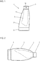
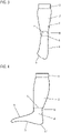
- FIG. 1 shows, as well as the side view according to figure 2 , a knitted part 1 according to the invention in its turned-over basic position, which is knitted as a circular knit on a circular knitting machine or as a flat knit on a flat knitting machine as a one-piece knitted part. It includes, see also those showing the knitted part 1 in the extended position Figures 3 and 4 , a tubular leg section 2 and a foot section 3 directly adjoining this.
- the leg section 2 preferably extends over the ankle to just before the heel, which is then followed by the foot section 3 . This is exemplified by the dashed dividing line 4 in 4 shown.
- a collar 5 is knitted on, which can be pulled, inter alia, to put on the knitted part 1 in the longitudinal direction.
- the knitted part 1 is, for example, a compressive knitted part in which the basic knitted fabric that forms the leg section 2 and the foot section 3 and is knitted from at least one basic knitted thread at least in sections and at least in the leg section 2 with a compressive property is equipped.
- the entire knitted part 1 can be compressive both in the leg section 2 and in the foot section 3 . This is achieved by introducing an elastic thread into the basic knitted fabric, for example as a weft thread, which resists the stretching in the circumferential direction, so that a compression pressure can be applied to the underlying, overlapped fabric.
- This measurement is preferably determined with the "HOSY” or “HOSYcan” test device, which is used in particular for measuring the compression pressure on compression textiles, in particular medical compression textiles, from the Hohenstein Textile Testing Institute GmbH & Co. KG. This applies to all exemplary embodiments described.
- the pulling element 7 is designed here as an annular, encircling pulling element 7, which is firmly attached at a lower end 8 to the inside 6 of the leg section 3, while the pulling element 7 is otherwise free or loose, as in FIGS Figures 3 and 4 shown, where the pulling element 7 is shown guided slightly inwards.
- an optical marking 18, for example a knitted-in thread or an imprint or the like, is provided on the outside of the pulling element 7, which preferably has a different color than the leg section 2 and the foot section 3.
- This optical marking 18 shows where the top 9 of the foot part 3 is, so that the user can use this as a guide and bring the knitted part 1 into a correct position relative to the foot or leg.
- Figures 1 - 4 show, the foot section 3 naturally also has an anatomical shape corresponding to the foot, in that a corresponding heel section 10 on the one hand and a corresponding toe section 11 on the other hand are provided on it. Correct positioning relative to the foot can now take place via this optical marking 18 , so that the foot can be slipped correctly into the foot section 3 .
- the knitted part 1 is first gripped by the annular pulling element 7 and pulled with the foot section 3 over the toes and further over the foot.
- pulling over the heel often turns out to be very difficult, especially if the knitted part 1 has compressive properties.
- the lower section of the leg section 2 which has a significantly reduced diameter and which is virtually attached to the in 4 bordering shown dividing line, are drawn over the heel, which is known and how 2 indicates is relatively wide in side view. This means that the knitted part 1 or the leg section 2 has to be greatly stretched in this area, which is sometimes very difficult with a compressive knitted fabric.
- annular pulling element 7 is arranged on the leg section 2, a strong direct pull can be exerted on the lower area of the leg section 2 and via this on the foot section 3 in the longitudinal direction, which significantly simplifies pulling over the heel area.
- the ring-shaped pulling element 7 or, in principle, the pulling element or elements is located in a longitudinal position of the leg section 2, which is in the vicinity of the lower end of the leg section, i.e. in the area of or adjacent to the transition to the Foot section 3, if one is provided. If no foot section 3 is provided, the pulling element 7 is located in the vicinity of or adjacent to the lower edge of the leg section 2, ie in the vicinity of the section which is greatly reduced in diameter. The pulling element 7 is consequently located in the area which is very narrow in diameter compared to the rest of the area of the leg section 2 adjoining it towards the waistband 5 and which is very difficult to pull over the heel. That is, a strong longitudinal pull can be applied very directed and directly to the corresponding leg portion area, which is difficult to pull on, via the pull member 7, thereby remarkably simplifying the pull-on operation.
- the pulling element 7 is also a knitted pulling element 7 which is knitted in one piece onto the leg section 2 with its end 8 .
- This knitting on as a quasi freely hanging, flexible and ring-shaped "lobe" is easily possible both on a circular knitting machine and on a flat knitting machine.
- the pulling element 7 is either knitted from the same knitted thread as the leg section 2 and, if necessary, likewise equipped with a compressive effect by inserting an elastic thread.
- a different elastic thread can be introduced into the pulling element 7 than in the leg section 2, by means of which the compression pressure of the pulling element 7 can be varied in a simple manner.
- FIG 8 1 shows an embodiment of a knitted part 1 according to the invention, here in the form of a long thigh-high stocking, again comprising a leg section 2 and a foot section 3 knitted onto it.
- the foot section 3 with an open toe end is shown here as an example.
- the knitted part 1 can be a non-compressive or a compressive knitted part 1, with the advantages of the arrangement of the pulling element(s) 7 naturally being given in particular in the case of a compressive knitted part 1.
- a first pulling element 7, here again by way of example a ring-shaped pulling element 7, is attached to the inside 6 of the tubular leg section 2, preferably in the B area, with its lower end 8, for example knitted in one piece or sewn on or glued on separately, as above described.
- the in is here 9
- the arm section area shown to the right of the pulling element 7 is slipped over the arm section area shown to the left of the pulling element 7 so that the pulling element 7 is exposed and can be grasped for pulling over.
- the collar 15 can then be gripped and the remaining arm section area pulled over the upper arm.
- the pulling element 7 can have an optical marking 18 which indicates the correct orientation of the knitted part 1 relative to the arm or hand, in particular if a hand section 17 is provided.
Landscapes
- Engineering & Computer Science (AREA)
- Textile Engineering (AREA)
- Socks And Pantyhose (AREA)
Priority Applications (3)
| Application Number | Priority Date | Filing Date | Title |
|---|---|---|---|
| EP20211940.0A EP4008819B1 (fr) | 2020-12-04 | 2020-12-04 | Pièce tricotée |
| US18/252,867 US20230413931A1 (en) | 2020-12-04 | 2021-10-14 | Knitted fabric article |
| PCT/EP2021/078429 WO2022117252A1 (fr) | 2020-12-04 | 2021-10-14 | Article en tissu tricoté |
Applications Claiming Priority (1)
| Application Number | Priority Date | Filing Date | Title |
|---|---|---|---|
| EP20211940.0A EP4008819B1 (fr) | 2020-12-04 | 2020-12-04 | Pièce tricotée |
Publications (2)
| Publication Number | Publication Date |
|---|---|
| EP4008819A1 true EP4008819A1 (fr) | 2022-06-08 |
| EP4008819B1 EP4008819B1 (fr) | 2025-02-05 |
Family
ID=73726692
Family Applications (1)
| Application Number | Title | Priority Date | Filing Date |
|---|---|---|---|
| EP20211940.0A Active EP4008819B1 (fr) | 2020-12-04 | 2020-12-04 | Pièce tricotée |
Country Status (3)
| Country | Link |
|---|---|
| US (1) | US20230413931A1 (fr) |
| EP (1) | EP4008819B1 (fr) |
| WO (1) | WO2022117252A1 (fr) |
Cited By (1)
| Publication number | Priority date | Publication date | Assignee | Title |
|---|---|---|---|---|
| US20230413931A1 (en) * | 2020-12-04 | 2023-12-28 | Medi Gmbh & Co. Kg | Knitted fabric article |
Citations (4)
| Publication number | Priority date | Publication date | Assignee | Title |
|---|---|---|---|---|
| FR2813323A1 (fr) * | 2000-08-23 | 2002-03-01 | Dim Sa | Article de vetement tubulaire tricote avec partie de maintien, notamment article chaussant |
| DE69912104T2 (de) * | 1998-03-02 | 2004-04-15 | Innothera Topic International S.A. | Vorrichtung zum anziehen einer kompressionsorthese in form von aus elastischem textilmaterial bestehenden stützstrumpfhose, -kniestrumpf, -socken |
| WO2009092932A1 (fr) * | 2008-01-08 | 2009-07-30 | Thuasne | Article textile tubulaire de compression |
| US20200205481A1 (en) * | 2018-12-28 | 2020-07-02 | Nike, Inc. | Sock with tab |
Family Cites Families (14)
| Publication number | Priority date | Publication date | Assignee | Title |
|---|---|---|---|---|
| US4005494A (en) * | 1975-10-20 | 1977-02-01 | The Pocket Socks Corporation | Pocket sock and method of knitting same |
| US4373215A (en) * | 1980-06-19 | 1983-02-15 | Wm. G. Leininger Knitting Company | Double sock construction |
| US4856112A (en) * | 1987-06-04 | 1989-08-15 | Effle Michael D | Powder cuff |
| US6192519B1 (en) * | 1999-03-19 | 2001-02-27 | Kathleen L. Coalter | Athletic sports pad |
| US6401247B1 (en) * | 2000-06-06 | 2002-06-11 | Williams, Iv Thomas Conrad | Protective sleeve for garment apparel |
| US6665876B1 (en) * | 2001-11-01 | 2003-12-23 | James O. Newman | Combination protective sleeve and head wear |
| US6826779B1 (en) * | 2003-08-25 | 2004-12-07 | Mckenzie Mark Christopher | Arm protection device |
| GB0326144D0 (en) * | 2003-11-07 | 2003-12-17 | Np Aerospace Ltd | Protective garments |
| US7076973B1 (en) * | 2005-01-28 | 2006-07-18 | Wigwam Mills, Inc. | Method and apparatus for making a sock having a looped tab |
| US7975886B2 (en) * | 2008-07-08 | 2011-07-12 | Mcallister John J | Sock donning system |
| KR200481379Y1 (ko) * | 2015-12-02 | 2016-09-22 | 정은화 | 보온부가 형성된 방한 의류 |
| US11717033B2 (en) * | 2019-09-05 | 2023-08-08 | Nike, Inc. | Easy Don and Doff sock |
| EP4008819B1 (fr) * | 2020-12-04 | 2025-02-05 | medi GmbH & Co. KG | Pièce tricotée |
| US20240260680A1 (en) * | 2023-02-06 | 2024-08-08 | Nike, Inc. | Sock with assistive pull loops |
-
2020
- 2020-12-04 EP EP20211940.0A patent/EP4008819B1/fr active Active
-
2021
- 2021-10-14 WO PCT/EP2021/078429 patent/WO2022117252A1/fr not_active Ceased
- 2021-10-14 US US18/252,867 patent/US20230413931A1/en active Pending
Patent Citations (4)
| Publication number | Priority date | Publication date | Assignee | Title |
|---|---|---|---|---|
| DE69912104T2 (de) * | 1998-03-02 | 2004-04-15 | Innothera Topic International S.A. | Vorrichtung zum anziehen einer kompressionsorthese in form von aus elastischem textilmaterial bestehenden stützstrumpfhose, -kniestrumpf, -socken |
| FR2813323A1 (fr) * | 2000-08-23 | 2002-03-01 | Dim Sa | Article de vetement tubulaire tricote avec partie de maintien, notamment article chaussant |
| WO2009092932A1 (fr) * | 2008-01-08 | 2009-07-30 | Thuasne | Article textile tubulaire de compression |
| US20200205481A1 (en) * | 2018-12-28 | 2020-07-02 | Nike, Inc. | Sock with tab |
Cited By (1)
| Publication number | Priority date | Publication date | Assignee | Title |
|---|---|---|---|---|
| US20230413931A1 (en) * | 2020-12-04 | 2023-12-28 | Medi Gmbh & Co. Kg | Knitted fabric article |
Also Published As
| Publication number | Publication date |
|---|---|
| US20230413931A1 (en) | 2023-12-28 |
| WO2022117252A1 (fr) | 2022-06-09 |
| EP4008819B1 (fr) | 2025-02-05 |
Similar Documents
| Publication | Publication Date | Title |
|---|---|---|
| DE69912104T2 (de) | Vorrichtung zum anziehen einer kompressionsorthese in form von aus elastischem textilmaterial bestehenden stützstrumpfhose, -kniestrumpf, -socken | |
| DE102013103914B3 (de) | Kompressives Rundgestrick zum Überziehen über eine ein Gelenk aufweisende Extremität | |
| DE60001707T2 (de) | Mehrschichtige kompressionsorthese und verfahren zum anziehen | |
| DE3872178T2 (de) | Verfahren zur herstellung einer zweischichtigen socke. | |
| CH712938B1 (de) | Kompressionskleidungsstück. | |
| EP3351667B1 (fr) | Corsage de contention ou collant de contention pourvu de corsage permettant le traitement par compression pendant la grossesse | |
| DE102007063148A1 (de) | Nahtloses Kompressionsgestrick und Verfahren zu dessen Herstellung | |
| EP4008819B1 (fr) | Pièce tricotée | |
| EP4137626B1 (fr) | Procédé de fabrication d'un article de compression sans couture sur un métier à tricoter rectiligne | |
| DE2340384A1 (de) | Verfahren zum herstellen eines artikels mit drei sich verengenden schlauchfoermigen wirkteilen von enganliegenden hosen oder dergleichen | |
| DE102016125409A1 (de) | Eingefasste Textilorthese | |
| EP1953284A2 (fr) | Tricot médicinal | |
| AT525012B1 (de) | Kompressionstextil mit integrierter An- und Ausziehhilfe | |
| EP1791453B1 (fr) | Systeme d'assistance a l'enfilage et au retrait de chaussettes | |
| EP3954817B1 (fr) | Vêtement pour jambes | |
| EP3647476B1 (fr) | Pièce tricotée médicale et procédé pour sa réalisatiion | |
| EP3473760B1 (fr) | Pièce tricotée | |
| DE102015122018B4 (de) | Kompressives Strickteil | |
| DE102018130930A1 (de) | Gestricktes Bekleidungsteil | |
| DE102004047248A1 (de) | An- und Ausziehhilfe für Strümpfe | |
| DE202004006379U1 (de) | An- und Ausziehhilfe für Strümpfe | |
| EP3699342A1 (fr) | Procédé de fabrication d'une pièce tricotée ainsi que pièce tricotée | |
| DE19806372C1 (de) | Socke und Verfahren zur Herstellung einer Socke | |
| DE3205109C2 (de) | Zweiteilige Strumpfwarenkombination | |
| EP3831994B1 (fr) | Pièce tricotée |
Legal Events
| Date | Code | Title | Description |
|---|---|---|---|
| PUAI | Public reference made under article 153(3) epc to a published international application that has entered the european phase |
Free format text: ORIGINAL CODE: 0009012 |
|
| STAA | Information on the status of an ep patent application or granted ep patent |
Free format text: STATUS: THE APPLICATION HAS BEEN PUBLISHED |
|
| AK | Designated contracting states |
Kind code of ref document: A1 Designated state(s): AL AT BE BG CH CY CZ DE DK EE ES FI FR GB GR HR HU IE IS IT LI LT LU LV MC MK MT NL NO PL PT RO RS SE SI SK SM TR |
|
| STAA | Information on the status of an ep patent application or granted ep patent |
Free format text: STATUS: REQUEST FOR EXAMINATION WAS MADE |
|
| 17P | Request for examination filed |
Effective date: 20221202 |
|
| RBV | Designated contracting states (corrected) |
Designated state(s): AL AT BE BG CH CY CZ DE DK EE ES FI FR GB GR HR HU IE IS IT LI LT LU LV MC MK MT NL NO PL PT RO RS SE SI SK SM TR |
|
| P01 | Opt-out of the competence of the unified patent court (upc) registered |
Effective date: 20230427 |
|
| GRAP | Despatch of communication of intention to grant a patent |
Free format text: ORIGINAL CODE: EPIDOSNIGR1 |
|
| STAA | Information on the status of an ep patent application or granted ep patent |
Free format text: STATUS: GRANT OF PATENT IS INTENDED |
|
| INTG | Intention to grant announced |
Effective date: 20241029 |
|
| GRAS | Grant fee paid |
Free format text: ORIGINAL CODE: EPIDOSNIGR3 |
|
| GRAA | (expected) grant |
Free format text: ORIGINAL CODE: 0009210 |
|
| STAA | Information on the status of an ep patent application or granted ep patent |
Free format text: STATUS: THE PATENT HAS BEEN GRANTED |
|
| AK | Designated contracting states |
Kind code of ref document: B1 Designated state(s): AL AT BE BG CH CY CZ DE DK EE ES FI FR GB GR HR HU IE IS IT LI LT LU LV MC MK MT NL NO PL PT RO RS SE SI SK SM TR |
|
| REG | Reference to a national code |
Ref country code: GB Ref legal event code: FG4D Free format text: NOT ENGLISH |
|
| REG | Reference to a national code |
Ref country code: CH Ref legal event code: EP |
|
| REG | Reference to a national code |
Ref country code: DE Ref legal event code: R096 Ref document number: 502020010352 Country of ref document: DE |
|
| REG | Reference to a national code |
Ref country code: IE Ref legal event code: FG4D Free format text: LANGUAGE OF EP DOCUMENT: GERMAN |
|
| REG | Reference to a national code |
Ref country code: NL Ref legal event code: MP Effective date: 20250205 |
|
| PG25 | Lapsed in a contracting state [announced via postgrant information from national office to epo] |
Ref country code: RS Free format text: LAPSE BECAUSE OF FAILURE TO SUBMIT A TRANSLATION OF THE DESCRIPTION OR TO PAY THE FEE WITHIN THE PRESCRIBED TIME-LIMIT Effective date: 20250505 |
|
| PG25 | Lapsed in a contracting state [announced via postgrant information from national office to epo] |
Ref country code: FI Free format text: LAPSE BECAUSE OF FAILURE TO SUBMIT A TRANSLATION OF THE DESCRIPTION OR TO PAY THE FEE WITHIN THE PRESCRIBED TIME-LIMIT Effective date: 20250205 |
|
| PG25 | Lapsed in a contracting state [announced via postgrant information from national office to epo] |
Ref country code: PL Free format text: LAPSE BECAUSE OF FAILURE TO SUBMIT A TRANSLATION OF THE DESCRIPTION OR TO PAY THE FEE WITHIN THE PRESCRIBED TIME-LIMIT Effective date: 20250205 |
|
| PG25 | Lapsed in a contracting state [announced via postgrant information from national office to epo] |
Ref country code: ES Free format text: LAPSE BECAUSE OF FAILURE TO SUBMIT A TRANSLATION OF THE DESCRIPTION OR TO PAY THE FEE WITHIN THE PRESCRIBED TIME-LIMIT Effective date: 20250205 |
|
| REG | Reference to a national code |
Ref country code: LT Ref legal event code: MG9D |
|
| PG25 | Lapsed in a contracting state [announced via postgrant information from national office to epo] |
Ref country code: NO Free format text: LAPSE BECAUSE OF FAILURE TO SUBMIT A TRANSLATION OF THE DESCRIPTION OR TO PAY THE FEE WITHIN THE PRESCRIBED TIME-LIMIT Effective date: 20250505 Ref country code: IS Free format text: LAPSE BECAUSE OF FAILURE TO SUBMIT A TRANSLATION OF THE DESCRIPTION OR TO PAY THE FEE WITHIN THE PRESCRIBED TIME-LIMIT Effective date: 20250605 |
|
| PG25 | Lapsed in a contracting state [announced via postgrant information from national office to epo] |
Ref country code: NL Free format text: LAPSE BECAUSE OF FAILURE TO SUBMIT A TRANSLATION OF THE DESCRIPTION OR TO PAY THE FEE WITHIN THE PRESCRIBED TIME-LIMIT Effective date: 20250205 |
|
| PG25 | Lapsed in a contracting state [announced via postgrant information from national office to epo] |
Ref country code: HR Free format text: LAPSE BECAUSE OF FAILURE TO SUBMIT A TRANSLATION OF THE DESCRIPTION OR TO PAY THE FEE WITHIN THE PRESCRIBED TIME-LIMIT Effective date: 20250205 |
|
| PG25 | Lapsed in a contracting state [announced via postgrant information from national office to epo] |
Ref country code: LV Free format text: LAPSE BECAUSE OF FAILURE TO SUBMIT A TRANSLATION OF THE DESCRIPTION OR TO PAY THE FEE WITHIN THE PRESCRIBED TIME-LIMIT Effective date: 20250205 Ref country code: PT Free format text: LAPSE BECAUSE OF FAILURE TO SUBMIT A TRANSLATION OF THE DESCRIPTION OR TO PAY THE FEE WITHIN THE PRESCRIBED TIME-LIMIT Effective date: 20250605 |
|
| PG25 | Lapsed in a contracting state [announced via postgrant information from national office to epo] |
Ref country code: GR Free format text: LAPSE BECAUSE OF FAILURE TO SUBMIT A TRANSLATION OF THE DESCRIPTION OR TO PAY THE FEE WITHIN THE PRESCRIBED TIME-LIMIT Effective date: 20250506 Ref country code: BG Free format text: LAPSE BECAUSE OF FAILURE TO SUBMIT A TRANSLATION OF THE DESCRIPTION OR TO PAY THE FEE WITHIN THE PRESCRIBED TIME-LIMIT Effective date: 20250205 |
|
| PG25 | Lapsed in a contracting state [announced via postgrant information from national office to epo] |
Ref country code: SE Free format text: LAPSE BECAUSE OF FAILURE TO SUBMIT A TRANSLATION OF THE DESCRIPTION OR TO PAY THE FEE WITHIN THE PRESCRIBED TIME-LIMIT Effective date: 20250205 |
|
| PG25 | Lapsed in a contracting state [announced via postgrant information from national office to epo] |
Ref country code: SM Free format text: LAPSE BECAUSE OF FAILURE TO SUBMIT A TRANSLATION OF THE DESCRIPTION OR TO PAY THE FEE WITHIN THE PRESCRIBED TIME-LIMIT Effective date: 20250205 |
|
| PG25 | Lapsed in a contracting state [announced via postgrant information from national office to epo] |
Ref country code: DK Free format text: LAPSE BECAUSE OF FAILURE TO SUBMIT A TRANSLATION OF THE DESCRIPTION OR TO PAY THE FEE WITHIN THE PRESCRIBED TIME-LIMIT Effective date: 20250205 |
|
| PG25 | Lapsed in a contracting state [announced via postgrant information from national office to epo] |
Ref country code: EE Free format text: LAPSE BECAUSE OF FAILURE TO SUBMIT A TRANSLATION OF THE DESCRIPTION OR TO PAY THE FEE WITHIN THE PRESCRIBED TIME-LIMIT Effective date: 20250205 Ref country code: CZ Free format text: LAPSE BECAUSE OF FAILURE TO SUBMIT A TRANSLATION OF THE DESCRIPTION OR TO PAY THE FEE WITHIN THE PRESCRIBED TIME-LIMIT Effective date: 20250205 |
|
| PG25 | Lapsed in a contracting state [announced via postgrant information from national office to epo] |
Ref country code: RO Free format text: LAPSE BECAUSE OF FAILURE TO SUBMIT A TRANSLATION OF THE DESCRIPTION OR TO PAY THE FEE WITHIN THE PRESCRIBED TIME-LIMIT Effective date: 20250205 |
|
| PG25 | Lapsed in a contracting state [announced via postgrant information from national office to epo] |
Ref country code: SK Free format text: LAPSE BECAUSE OF FAILURE TO SUBMIT A TRANSLATION OF THE DESCRIPTION OR TO PAY THE FEE WITHIN THE PRESCRIBED TIME-LIMIT Effective date: 20250205 |
|
| REG | Reference to a national code |
Ref country code: DE Ref legal event code: R097 Ref document number: 502020010352 Country of ref document: DE |
|
| PLBE | No opposition filed within time limit |
Free format text: ORIGINAL CODE: 0009261 |
|
| STAA | Information on the status of an ep patent application or granted ep patent |
Free format text: STATUS: NO OPPOSITION FILED WITHIN TIME LIMIT |
|
| REG | Reference to a national code |
Ref country code: CH Ref legal event code: L10 Free format text: ST27 STATUS EVENT CODE: U-0-0-L10-L00 (AS PROVIDED BY THE NATIONAL OFFICE) Effective date: 20251217 |
|
| REG | Reference to a national code |
Ref country code: CH Ref legal event code: U11 Free format text: ST27 STATUS EVENT CODE: U-0-0-U10-U11 (AS PROVIDED BY THE NATIONAL OFFICE) Effective date: 20260101 |
|
| PGFP | Annual fee paid to national office [announced via postgrant information from national office to epo] |
Ref country code: DE Payment date: 20251211 Year of fee payment: 6 |
|
| PGFP | Annual fee paid to national office [announced via postgrant information from national office to epo] |
Ref country code: GB Payment date: 20251219 Year of fee payment: 6 |
|
| 26N | No opposition filed |
Effective date: 20251106 |
|
| PGFP | Annual fee paid to national office [announced via postgrant information from national office to epo] |
Ref country code: IT Payment date: 20251223 Year of fee payment: 6 |
|
| PGFP | Annual fee paid to national office [announced via postgrant information from national office to epo] |
Ref country code: FR Payment date: 20251229 Year of fee payment: 6 |
|
| PGFP | Annual fee paid to national office [announced via postgrant information from national office to epo] |
Ref country code: CH Payment date: 20260101 Year of fee payment: 6 |