EP4100295B1 - Ensemble de support pour châssis d'un véhicule ferroviaire - Google Patents
Ensemble de support pour châssis d'un véhicule ferroviaire Download PDFInfo
- Publication number
- EP4100295B1 EP4100295B1 EP21718032.2A EP21718032A EP4100295B1 EP 4100295 B1 EP4100295 B1 EP 4100295B1 EP 21718032 A EP21718032 A EP 21718032A EP 4100295 B1 EP4100295 B1 EP 4100295B1
- Authority
- EP
- European Patent Office
- Prior art keywords
- support
- chassis
- carrier
- assembly according
- carrier assembly
- Prior art date
- Legal status (The legal status is an assumption and is not a legal conclusion. Google has not performed a legal analysis and makes no representation as to the accuracy of the status listed.)
- Active
Links
Images

Classifications
-
- B—PERFORMING OPERATIONS; TRANSPORTING
- B61—RAILWAYS
- B61F—RAIL VEHICLE SUSPENSIONS, e.g. UNDERFRAMES, BOGIES OR ARRANGEMENTS OF WHEEL AXLES; RAIL VEHICLES FOR USE ON TRACKS OF DIFFERENT WIDTH; PREVENTING DERAILING OF RAIL VEHICLES; WHEEL GUARDS, OBSTRUCTION REMOVERS OR THE LIKE FOR RAIL VEHICLES
- B61F5/00—Constructional details of bogies; Connections between bogies and vehicle underframes; Arrangements or devices for adjusting or allowing self-adjustment of wheel axles or bogies when rounding curves
- B61F5/50—Other details
- B61F5/52—Bogie frames
-
- B—PERFORMING OPERATIONS; TRANSPORTING
- B61—RAILWAYS
- B61F—RAIL VEHICLE SUSPENSIONS, e.g. UNDERFRAMES, BOGIES OR ARRANGEMENTS OF WHEEL AXLES; RAIL VEHICLES FOR USE ON TRACKS OF DIFFERENT WIDTH; PREVENTING DERAILING OF RAIL VEHICLES; WHEEL GUARDS, OBSTRUCTION REMOVERS OR THE LIKE FOR RAIL VEHICLES
- B61F5/00—Constructional details of bogies; Connections between bogies and vehicle underframes; Arrangements or devices for adjusting or allowing self-adjustment of wheel axles or bogies when rounding curves
- B61F5/50—Other details
-
- H—ELECTRICITY
- H01—ELECTRIC ELEMENTS
- H01Q—ANTENNAS, i.e. RADIO AERIALS
- H01Q1/00—Details of, or arrangements associated with, antennas
- H01Q1/27—Adaptation for use in or on movable bodies
- H01Q1/32—Adaptation for use in or on road or rail vehicles
Definitions
- the invention relates to a support arrangement for a chassis of a rail vehicle, in particular for a vehicle-side, railway safety or control technology device, in particular an antenna support arrangement, connectable to a chassis frame.
- support arrangements are often provided, which are, for example, rigidly connected to a chassis frame of a chassis of a rail vehicle, but as a result of which large dynamic forces can be introduced into the chassis frame and strong vibration excitation can occur.
- the support arrangement itself and components that are connected to the support arrangement sometimes have high masses and often put a lot of strain on the chassis frame.
- antennas of a train control system often have to be arranged at a certain position on the support arrangement (e.g. in the middle), for example to enable data transmission with an infrastructure-side balise in the middle of the track.
- CN 110733525 A known in which support arrangements for antennas are shown. These support arrangements are connected to longitudinal beams of a chassis frame of a rail vehicle chassis and include curved rods which have a Allow the antennas to be arranged in front of the chassis in the area in front of the wheels of the chassis.
- the support arrangement is designed to arrange antennas further away from the wheels (eg towards the center of the chassis). Furthermore, it shows EP 3 243 724 A1 a chassis for a rail vehicle, an adapter being mounted on a chassis frame and a wheel, on which, for example, current collectors or train control antennas can be arranged.
- the adapter is provided on the side of the chassis. It is not clear to what extent the adapter is also suitable for components that are to be arranged, for example, in an area in front of the chassis.
- the invention is therefore based on the object of specifying a distance-bridging support arrangement with mechanical decoupling in relation to the chassis frame that has been further developed compared to the prior art.
- this object is achieved with a carrying arrangement of the type mentioned at the outset, in which a carrying device is provided, which can be connected in an articulated and elastic manner to at least a first longitudinal member of the chassis frame and can additionally be supported in an articulated and elastic manner at least on the chassis frame or on at least one further chassis component , wherein the carrying device can be connected to the at least first longitudinal beam by means of a pendulum support and the carrying device is L-shaped, with a first leg of the carrying device being connectable to the at least first longitudinal beam by means of the pendulum support.
- This measure allows the carrying device to be constructed more easily when connecting the carrying device to the chassis frame, since the carrying device is supported on the chassis due to elastic mounting
- the first longitudinal beam only puts a moderate load on the chassis frame mechanically, especially dynamically.
- An L-shaped design of the carrying device leads to great stability and advantageous strength properties of the carrying device when the first leg is connected to the first longitudinal beam by means of the pendulum support.
- first leg is tubular and is firmly connected to a second leg of the carrying device designed as a rocker.
- This measure brings about a reduction in the mass of the carrying device without significantly influencing the advantageous strength properties of the carrying device.
- the carrying device can be supported on at least a first axle bearing housing of the chassis by means of at least a first support.
- the carrying device can be supported on a cross member of the chassis frame by means of at least a first support.
- a further alternative solution for supporting the carrying device is achieved if the carrying device can be supported on a roll support of the rail vehicle by means of at least a first support.
- the first axle bearing housing or the roll support is provided as a further chassis component on which the carrying device can be supported, the load on the chassis frame is relieved.
- the at least first support is angled or curved.
- the carrying device can be connected in an articulated and elastic manner to a second longitudinal member of the chassis frame, with a second leg of the carrying device being connectable to the second longitudinal member by means of an elastic element.
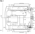
- Fig. 1 shows a floor plan of a chassis of a rail vehicle in a schematic and partial representation.
- the chassis has a first wheel set 1 and an in Fig. 1 invisible second set of wheels.
- the first wheelset 1 is internally mounted, ie a first wheelset bearing device 2 and a second wheelset bearing device 3 of the first wheelset 1 are arranged within an area delimited by a first wheel 4 and a second wheel 5 of the first wheelset 1.
- the second wheelset has the same design as the first wheelset 1 and is also designed as an internally mounted wheelset.
- the first wheelset bearing device 2 and the second wheelset bearing device 3 include wheelset bearings of the first wheelset 1. Furthermore, the first wheelset bearing device 2 has a first wheelset bearing housing 6, the second wheelset bearing device 3 has a second wheelset bearing housing 7.
- a chassis frame 8 is coupled to the first wheelset 1 and the second wheelset.
- a first primary spring 11 is provided between a first longitudinal member 9 of the chassis frame 8 and the first wheelset bearing housing 6, and a second primary spring 12 is provided between a second longitudinal member 10 of the chassis frame 8 and the second wheelset bearing housing 7.
- a first wheelset guiding device 13 is provided between the first longitudinal member 9 and the first wheelset 1
- a second wheelset guiding device 14 is provided between the second longitudinal member 10 and the first wheelset 1.
- the first wheelset guiding device 13 has a first Swing arm 15 and a first wheelset guide bushing 17.
- the first swing arm 15 is formed in one piece with the first axle bearing housing 6.
- the first swing arm 15 is coupled to the chassis frame 8 via the first wheelset guide bushing 17.
- the second wheelset guide device 14 has the same design as the first wheelset guide device 13 and includes a second swing arm 16 and a second wheelset guide bushing 18, via which the second swing arm 16 is connected to the chassis frame 8.
- the second wheel set is connected to the chassis frame 8 according to the same principle as the first wheel set 1.
- a first gear 20 is connected to a wheelset shaft 19 of the first wheelset 1, whereby driving forces and torques are transmitted from an electric first drive motor 21 via a first clutch 22, which is arranged between the first drive motor 21 and the first gear 20, and the first gear 20 be transferred to the first wheelset 1.
- the drive motor 21 is connected to the first longitudinal member 9 via a first engine mount 23 and to a cross member 26 of the chassis frame 8 via a second engine mount 24 and a third engine mount 25
- the first transmission 20 is connected to the second longitudinal member 10 via a transmission torque support 27.
- the chassis has a second drive motor, a second transmission and a second clutch, which in Fig. 1 are not visible and are designed according to the same principles as the first drive motor 21, the first transmission 20 and the first clutch 22 and are connected to each other and to the chassis frame 8 and the second wheelset.
- the support arrangement is therefore designed as an antenna support arrangement and has a support device 29 designed as an antenna support.
- the carrying device 29 is connected in an articulated and elastic manner to the first longitudinal beam 9 and in an articulated and elastic manner to the second longitudinal beam 10.
- a pendulum support 30 made of steel is arranged between the carrying device 29 and the first longitudinal beam 9.
- the pendulum support 30 is connected to the carrying device 29 by means of a first swivel joint 31 and to the first longitudinal beam 9 by means of a second swivel joint 32.
- the first swivel joint 31 and the second swivel joint 32 are designed as bush-shaped metal elastomer elements, which have an elastic behavior in particular in the direction of their longitudinal joint axes and radially with respect to their longitudinal joint axes.
- a first longitudinal joint axis 37 of the first swivel joint 31 is arranged at right angles to a second longitudinal joint axis 38 of the second swivel joint 32.
- the second longitudinal joint axis 38 is aligned parallel to a chassis transverse axis 43.
- the carrying device 29 is thus connected to the first longitudinal member 9 in an articulated manner with respect to the chassis transverse axis 43.
- the carrying device 29 is L-shaped, with a first leg 44 of the carrying device 29 being connected to the first longitudinal beam 9 by means of the pendulum support 30 and a second leg 45 of the carrying device 29 being connected to the second longitudinal beam 10 by means of an elastic element 46.
- the elastic element 46 is designed as a bush-shaped metal elastomer element and has an elastic behavior in the direction of its elastic element longitudinal axis 47 and radially with respect to its elastic element longitudinal axis 47.
- the elastic element longitudinal axis 47 is aligned parallel to the chassis transverse axis 43.
- the carrying device 29 is thus connected to the second longitudinal member 10 in an articulated manner with respect to the chassis transverse axis 43.
- the first leg 44 is tubular and welded to the second leg 45, which is designed as a rocker, i.e. firmly connected to the second leg 45.
- the second leg 45 is cylindrical in the area of the first leg 44 and tapers in the direction of the second longitudinal member 10.
- the first leg 44 and the second leg 45 are made of steel.
- the carrying device 29 is additionally supported in an articulated and elastic manner not on the chassis frame 8, but on the first axle bearing housing 6 and the second axle bearing housing 7, i.e. on further chassis components.
- a first support 48 is arranged between the first leg 44 of the carrying device 29 and the first axle bearing housing 6 and a second support 49 is arranged between the first leg 44 and the second axle bearing housing 7.
- the first support 48 and the second support 49 are made of steel and aligned parallel to a chassis longitudinal axis 50.
- the carrying device 29 is thus supported in the direction of the chassis longitudinal axis 50 on the first axle bearing housing 6 and on the second axle bearing housing 7.
- the first support 48 has a third swivel joint 33 at its first end and a fourth swivel joint 34 at its second end, the first support 48 being coupled to the carrying device 29 via the third swivel joint 33 and to the first axle bearing housing 6 via the fourth swivel joint 34 is.
- the second support 49 is structurally the same as the first support 48 and is connected to the carrying device 29 via a fifth swivel joint 35 and a sixth Swivel joint 36 coupled to the second wheelset bearing housing 7.
- the third swivel joint 33, the fourth swivel joint 34, the fifth swivel joint 35 and the sixth swivel joint 36 are designed as bush-shaped metal elastomer elements and have elastic behavior in the direction of their longitudinal joint axes and radially with respect to their longitudinal joint axes.
- a third longitudinal joint axis 39 of the third swivel joint 33, a fourth longitudinal joint axis 40 of the fourth swivel joint 34, a fifth longitudinal joint axis 41 of the fifth swivel joint 35 and a sixth longitudinal joint axis 42 of the sixth swivel joint 36 are aligned parallel to the chassis transverse axis 43.
- the carrying device 29 is thus supported in an articulated manner with respect to the chassis transverse axis 43 on the first axle bearing housing 6 and on the second axle bearing housing 7.
- a holder 51 is welded to the first leg 44 of the carrying device 29, and the antenna 28 of the train control system, which in this exemplary first embodiment variant of a carrying arrangement according to the invention is designed as a European Train Control System (ETCS), is in turn connected to the holder 51.
- ECS European Train Control System
- the holder 51 and the antenna 28 are arranged centrally with respect to a track, not shown.
- the chassis of Fig. 1 is designed as an internally mounted chassis. According to the invention, however, it is of course conceivable to also use the support arrangement according to the invention for an externally mounted chassis.
- a sensor or sensors of a diagnostic or monitoring system is or are connected to the carrying device 29 (e.g. a camera for detecting track damage, etc.).
- the carrying device 29 is not connected to the second longitudinal beam 10 or to the first longitudinal beam 9 connected and/or not supported on the second axle bearing housing 7 or on the first axle bearing housing 6.
- a sanding device or a sanding pipe or a rail clearer etc. can be connected to such a variant of a carrying arrangement according to the invention.
- a section of a chassis of a rail vehicle with an exemplary second embodiment variant of a support arrangement according to the invention is disclosed as a floor plan in a schematic representation, which is similar to that chassis and that support arrangement shown in Fig. 1 are shown. There will therefore be in Fig. 2 partly the same reference numbers as in Fig. 1 used.
- FIG. 2 shows the carrying arrangement of Fig. 2 a carrying device 29, which is supported in an articulated and elastic manner on a cross member 26 of a chassis frame 8 by means of a first support 48 and a second support 49.
- the first support 48 and the second support 49 are structurally similar and have the same connection technology as the first support 48 and the second support 49, which are shown in Fig. 1 are shown, and aligned parallel to a chassis longitudinal axis 50.
- Fig. 1 In contrast to Fig. 1 are the first support 48 and the second support 49 from Fig. 2 arranged offset towards the center of the carrying device 29.
- FIG. 1 Another difference to Fig. 1 is that the first support 48 and the second support 49 are angled.
- the first support 48 has a first angle 52
- the second support 49 has a second angle 53.
- the first support 48 and the second support 49 are guided obliquely downwards from the carrying device 29.
- the first support 48 runs below a wheelset shaft 19 of the chassis and below a first engine mount 23, over which a first drive motor 21 of the chassis is connected to the chassis frame 8, to the cross member 26.
- the second support 49 runs below the wheelset shaft 19 and below a first gear 20 of the chassis to the cross member 26.
- the first support 48 and the second support 49 are not angled, but curved are.
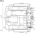
- a section of a chassis of a rail vehicle with an exemplary third embodiment variant of a support arrangement according to the invention is shown as a schematic floor plan, which is similar to that chassis and that support arrangement shown in Fig. 1 and Fig. 2 are revealed. There will therefore be in Fig. 3 partly the same reference numbers as in Fig. 1 and Fig. 2 used.
- the chassis points accordingly Fig. 3 a roll support 54, which is designed as a metallic torsion spring, aligned parallel to a chassis transverse axis 43 and rigidly coupled to a first axle bearing housing 6 and a second axle bearing housing 7 of the chassis.
- a first support 48 and a second support 49 are supported, which are connected to a carrying device 29 of the carrying arrangement.
- the first support 48 and the second support 49 are structurally similar and have the same connection technology as the first support 48 and the second support 49, which are in Fig. 1 are shown. Compared to Fig. 1 have the first support 48 and the second support 49 from Fig. 3 shorter lengths and are arranged offset towards the center of the carrying device 29.
- the carrying device 29 is supported in an articulated and elastic manner on the roll support 54.
Landscapes
- Engineering & Computer Science (AREA)
- Mechanical Engineering (AREA)
- Vibration Prevention Devices (AREA)
- Arrangement Or Mounting Of Propulsion Units For Vehicles (AREA)
Claims (14)
- Système porteur pour un train de roulement d'un véhicule ferroviaire, en particulier pour un dispositif, en particulier un système porteur d'antenne, situé côté véhicule, relatif au pilotage ou à la sécurité de la voie et pouvant être relié à un châssis de train de roulement (8), dans lequel un dispositif porteur (29) est prévu, qui peut être relié de manière articulée et élastique à au moins un premier longeron (9) du châssis de train de roulement (8) et qui peut en outre être soutenu de manière articulée et élastique au moins au niveau du châssis de train de roulement (8) ou au niveau d'au moins un autre composant de châssis, dans lequel le dispositif porteur (29) peut être relié au au moins un premier longeron (9) au moyen d'un support formant balancier (30), caractérisé en ce que le dispositif porteur (29) est réalisé en forme de L, dans lequel une première branche (44) du dispositif porteur (29) peut être reliée au au moins un premier longeron (9) au moyen du support formant balancier (30).
- Système porteur selon la revendication 1, caractérisé en ce que la première branche (44) est de forme tubulaire et est reliée de manière fixe à une seconde branche (45) du dispositif de transport (29) réalisée sous forme de bras oscillant.
- Système porteur selon la revendication 1 ou 2, caractérisé en ce que le support formant balancier (30) est relié au dispositif porteur (29) au moyen d'une première articulation pivotante (31) et peut être relié au au moins un premier longeron (9) au moyen d'une deuxième articulation pivotante (32).
- Système porteur selon la revendication 3, caractérisé en ce qu'un premier axe longitudinal d'articulation (37) de la première articulation pivotante (31) est agencé à angle droit par rapport à un deuxième axe longitudinal d'articulation (38) de la deuxième articulation pivotante (32).
- Système porteur selon l'une quelconque des revendications 1 à 4, caractérisé en ce que le dispositif porteur (29) peut être relié au au moins un premier longeron (9) de manière articulée par rapport à un axe transversal de châssis (43).
- Système porteur selon l'une quelconque des revendications 1 à 5, caractérisé en ce que le dispositif porteur (29) peut être soutenu au niveau du cadre de châssis (8) ou au niveau de l'autre composant de châssis dans la direction d'un axe longitudinal de châssis (50).
- Système porteur selon l'une quelconque des revendications 1 à 6, caractérisé en ce que le dispositif porteur (29) peut être soutenu au niveau du cadre de châssis (8) ou au niveau de l'autre composant de châssis de manière articulée par rapport à l'axe transversal de châssis (43).
- Système porteur selon l'une quelconque des revendications 1 à 7, caractérisé en ce que le dispositif porteur (29) peut être soutenu au niveau d'au moins un premier logement de palier d'essieu monté (6) du châssis au moyen d'au moins un premier support (48).
- Système porteur selon l'une quelconque des revendications 1 à 7, caractérisé en ce que le dispositif porteur (29) peut être soutenu au niveau d'une traverse (26) du cadre de châssis (8) au moyen d'au moins un premier support (48).
- Système porteur selon l'une quelconque des revendications 1 à 7, caractérisé en ce que le dispositif porteur (29) peut être soutenu au niveau d'une barre anti-roulis (54) du véhicule ferroviaire au moyen d'au moins un premier support (48).
- Système porteur selon l'une quelconque des revendications 8 à 10, caractérisé en ce que le au moins un premier support (48) présente une troisième articulation pivotante (33) au niveau d'une première extrémité et une quatrième articulation pivotante (34) au niveau d'une deuxième extrémité.
- Système porteur selon l'une quelconque des revendications 8 à 11, caractérisé en ce que le au moins un premier support (48) est réalisé de manière coudée ou courbée.
- Système porteur selon l'une quelconque des revendications 1 à 12, caractérisé en ce que le dispositif porteur (29) peut être relié de manière articulée et élastique à un deuxième longeron (10) du cadre de châssis (8), dans lequel une seconde branche (45) du dispositif porteur (29) peut être reliée au deuxième longeron (10) au moyen d'un élément élastique (46).
- Train de roulement d'un véhicule ferroviaire présentant un système porteur selon l'une quelconque des revendications 1 à 13.
Applications Claiming Priority (2)
| Application Number | Priority Date | Filing Date | Title |
|---|---|---|---|
| ATA50266/2020A AT523656B1 (de) | 2020-03-31 | 2020-03-31 | Trageanordnung für ein Fahrwerk eines Schienenfahrzeugs |
| PCT/EP2021/057763 WO2021198021A1 (fr) | 2020-03-31 | 2021-03-25 | Ensemble de support pour châssis d'un véhicule ferroviaire |
Publications (2)
| Publication Number | Publication Date |
|---|---|
| EP4100295A1 EP4100295A1 (fr) | 2022-12-14 |
| EP4100295B1 true EP4100295B1 (fr) | 2024-01-10 |
Family
ID=75478003
Family Applications (1)
| Application Number | Title | Priority Date | Filing Date |
|---|---|---|---|
| EP21718032.2A Active EP4100295B1 (fr) | 2020-03-31 | 2021-03-25 | Ensemble de support pour châssis d'un véhicule ferroviaire |
Country Status (5)
| Country | Link |
|---|---|
| US (1) | US12594975B2 (fr) |
| EP (1) | EP4100295B1 (fr) |
| CN (1) | CN219257341U (fr) |
| AT (1) | AT523656B1 (fr) |
| WO (1) | WO2021198021A1 (fr) |
Families Citing this family (2)
| Publication number | Priority date | Publication date | Assignee | Title |
|---|---|---|---|---|
| WO2021063947A1 (fr) * | 2019-09-30 | 2021-04-08 | Siemens Mobility Austria Gmbh | Train de roulement pour véhicule ferroviaire |
| DE102022206109A1 (de) | 2022-06-20 | 2023-12-21 | Siemens Mobility GmbH | Fahrwerk für ein Schienenfahrzeug und Schienenfahrzeug |
Family Cites Families (10)
| Publication number | Priority date | Publication date | Assignee | Title |
|---|---|---|---|---|
| US6079335A (en) | 1999-02-23 | 2000-06-27 | Buckeye Steel Castings Company | Unsprung third rail collector beam support for a swing arm primary suspension railway truck |
| JP2004148948A (ja) | 2002-10-30 | 2004-05-27 | Kawasaki Heavy Ind Ltd | 鉄道車両用台車 |
| CN202094272U (zh) * | 2011-05-31 | 2011-12-28 | 长春轨道客车股份有限公司 | 高速动车组转向架用atp天线偏置悬挂装置 |
| AT516912A3 (de) * | 2015-02-17 | 2017-12-15 | Siemens Ag Oesterreich | Verbindungsträger für zwei Längsträger eines Schienenfahrzeugs |
| CN204956505U (zh) * | 2015-09-30 | 2016-01-13 | 南车南京浦镇车辆有限公司 | 一种用于轨道车辆的天线设备固定装置 |
| CN105216823B (zh) * | 2015-09-30 | 2018-05-25 | 中车南京浦镇车辆有限公司 | 一种用于轨道车辆的天线设备固定装置 |
| AT518697B1 (de) | 2016-05-10 | 2021-12-15 | Siemens Mobility Austria Gmbh | Fahrwerk für ein Schienenfahrzeug |
| CN106043343A (zh) * | 2016-06-13 | 2016-10-26 | 中车青岛四方机车车辆股份有限公司 | 轨道车辆转向架水平梁防脱吊挂装置及其安装方法、轨道车辆 |
| JP6726612B2 (ja) * | 2016-12-16 | 2020-07-22 | 川崎重工業株式会社 | 鉄道車両用台車 |
| CN110733525B (zh) | 2019-10-31 | 2025-06-03 | 中车南京浦镇车辆有限公司 | 一种天线支架与转向架的定位结构 |
-
2020
- 2020-03-31 AT ATA50266/2020A patent/AT523656B1/de not_active IP Right Cessation
-
2021
- 2021-03-25 US US17/915,895 patent/US12594975B2/en active Active
- 2021-03-25 WO PCT/EP2021/057763 patent/WO2021198021A1/fr not_active Ceased
- 2021-03-25 CN CN202190000396.3U patent/CN219257341U/zh active Active
- 2021-03-25 EP EP21718032.2A patent/EP4100295B1/fr active Active
Also Published As
| Publication number | Publication date |
|---|---|
| WO2021198021A1 (fr) | 2021-10-07 |
| EP4100295A1 (fr) | 2022-12-14 |
| CN219257341U (zh) | 2023-06-27 |
| AT523656B1 (de) | 2021-11-15 |
| US20230202536A1 (en) | 2023-06-29 |
| AT523656A1 (de) | 2021-10-15 |
| US12594975B2 (en) | 2026-04-07 |
Similar Documents
| Publication | Publication Date | Title |
|---|---|---|
| EP4100295B1 (fr) | Ensemble de support pour châssis d'un véhicule ferroviaire | |
| EP4013655B1 (fr) | Train de roulement pour véhicule ferroviaire | |
| EP3272614B1 (fr) | Train de roulement pour un véhicule sur rail | |
| DE102011112053A1 (de) | Einzelradaufhängung und Fahrschemel | |
| EP3544875B1 (fr) | Châssis pour véhicules sur rails | |
| DE102013224582A1 (de) | Fahrwerk für ein Schienenfahrzeug | |
| WO2022161653A1 (fr) | Arbre creux pour un système de stabilisation de roulis pour un véhicule, système de stabilisation de roulis et procédé de fabrication d'un arbre creux | |
| EP1685014B2 (fr) | Chassis propulse pour vehicules sur rails, en particulier pour boggies de vehicules a plancher bas | |
| WO2009144319A1 (fr) | Bogie à châssis séparé et unité de couplage moteur-transmission | |
| DE102017106085A1 (de) | Radaufhängungsanordnung für ein Fahrzeug | |
| DE102016007496B4 (de) | Antriebsmodul für ein Kraftfahrzeug sowie entsprechendes Kraftfahrzeug | |
| EP4491487A2 (fr) | Train de roulement pour un véhicule ferroviaire et véhicule ferroviaire comprenant au moins un train de roulement, véhicule ferroviaire comprenant au moins un wagon de chemin de fer et procédé de réglage en hauteur d'une caisse d'un véhicule ferroviaire | |
| DE102006004960A1 (de) | Angetriebe Fahrzeugachse mit Einzelradaufhängung | |
| EP3243724A1 (fr) | Train de roulement pour un véhicule sur rail | |
| EP2061690B1 (fr) | Fixation pour un guide d'essieu d'un véhicule ferroviaire | |
| EP4228948B1 (fr) | Train de roulement pour un véhicule ferroviaire | |
| DE102017005165A1 (de) | Fahrzeug | |
| EP4121332B1 (fr) | Ensemble pour maintenir un couple | |
| EP3974280B1 (fr) | Bogie pour véhicule ferroviaire | |
| AT527594B1 (de) | Antrieb und Fahrwerk für ein Schienenfahrzeug | |
| DE102013210235A1 (de) | Drehmomentstütze für ein Schienenfahrzeug | |
| AT528197B1 (de) | Fahrwerk für ein Schienenfahrzeug und Schienenfahrzeug | |
| EP3750775B1 (fr) | Procédé et dispositif de détermination d'une inclinaison de fonctionnement dans des véhicules | |
| DE2709967A1 (de) | Triebfahrzeug, insbesondere schienentriebfahrzeug | |
| DE102021213986A1 (de) | Achsbaugruppe für ein Fahrzeug |
Legal Events
| Date | Code | Title | Description |
|---|---|---|---|
| STAA | Information on the status of an ep patent application or granted ep patent |
Free format text: STATUS: UNKNOWN |
|
| STAA | Information on the status of an ep patent application or granted ep patent |
Free format text: STATUS: THE INTERNATIONAL PUBLICATION HAS BEEN MADE |
|
| PUAI | Public reference made under article 153(3) epc to a published international application that has entered the european phase |
Free format text: ORIGINAL CODE: 0009012 |
|
| STAA | Information on the status of an ep patent application or granted ep patent |
Free format text: STATUS: REQUEST FOR EXAMINATION WAS MADE |
|
| 17P | Request for examination filed |
Effective date: 20220906 |
|
| AK | Designated contracting states |
Kind code of ref document: A1 Designated state(s): AL AT BE BG CH CY CZ DE DK EE ES FI FR GB GR HR HU IE IS IT LI LT LU LV MC MK MT NL NO PL PT RO RS SE SI SK SM TR |
|
| DAV | Request for validation of the european patent (deleted) | ||
| DAX | Request for extension of the european patent (deleted) | ||
| GRAP | Despatch of communication of intention to grant a patent |
Free format text: ORIGINAL CODE: EPIDOSNIGR1 |
|
| STAA | Information on the status of an ep patent application or granted ep patent |
Free format text: STATUS: GRANT OF PATENT IS INTENDED |
|
| INTG | Intention to grant announced |
Effective date: 20230823 |
|
| GRAS | Grant fee paid |
Free format text: ORIGINAL CODE: EPIDOSNIGR3 |
|
| GRAA | (expected) grant |
Free format text: ORIGINAL CODE: 0009210 |
|
| STAA | Information on the status of an ep patent application or granted ep patent |
Free format text: STATUS: THE PATENT HAS BEEN GRANTED |
|
| AK | Designated contracting states |
Kind code of ref document: B1 Designated state(s): AL AT BE BG CH CY CZ DE DK EE ES FI FR GB GR HR HU IE IS IT LI LT LU LV MC MK MT NL NO PL PT RO RS SE SI SK SM TR |
|
| REG | Reference to a national code |
Ref country code: GB Ref legal event code: FG4D Free format text: NOT ENGLISH |
|
| REG | Reference to a national code |
Ref country code: CH Ref legal event code: EP |
|
| REG | Reference to a national code |
Ref country code: DE Ref legal event code: R096 Ref document number: 502021002446 Country of ref document: DE |
|
| REG | Reference to a national code |
Ref country code: IE Ref legal event code: FG4D Free format text: LANGUAGE OF EP DOCUMENT: GERMAN |
|
| REG | Reference to a national code |
Ref country code: LT Ref legal event code: MG9D |
|
| REG | Reference to a national code |
Ref country code: NL Ref legal event code: MP Effective date: 20240110 |
|
| PG25 | Lapsed in a contracting state [announced via postgrant information from national office to epo] |
Ref country code: NL Free format text: LAPSE BECAUSE OF FAILURE TO SUBMIT A TRANSLATION OF THE DESCRIPTION OR TO PAY THE FEE WITHIN THE PRESCRIBED TIME-LIMIT Effective date: 20240110 |
|
| PG25 | Lapsed in a contracting state [announced via postgrant information from national office to epo] |
Ref country code: NL Free format text: LAPSE BECAUSE OF FAILURE TO SUBMIT A TRANSLATION OF THE DESCRIPTION OR TO PAY THE FEE WITHIN THE PRESCRIBED TIME-LIMIT Effective date: 20240110 |
|
| PG25 | Lapsed in a contracting state [announced via postgrant information from national office to epo] |
Ref country code: IS Free format text: LAPSE BECAUSE OF FAILURE TO SUBMIT A TRANSLATION OF THE DESCRIPTION OR TO PAY THE FEE WITHIN THE PRESCRIBED TIME-LIMIT Effective date: 20240510 |
|
| PG25 | Lapsed in a contracting state [announced via postgrant information from national office to epo] |
Ref country code: LT Free format text: LAPSE BECAUSE OF FAILURE TO SUBMIT A TRANSLATION OF THE DESCRIPTION OR TO PAY THE FEE WITHIN THE PRESCRIBED TIME-LIMIT Effective date: 20240110 |
|
| PG25 | Lapsed in a contracting state [announced via postgrant information from national office to epo] |
Ref country code: GR Free format text: LAPSE BECAUSE OF FAILURE TO SUBMIT A TRANSLATION OF THE DESCRIPTION OR TO PAY THE FEE WITHIN THE PRESCRIBED TIME-LIMIT Effective date: 20240411 |
|
| PG25 | Lapsed in a contracting state [announced via postgrant information from national office to epo] |
Ref country code: HR Free format text: LAPSE BECAUSE OF FAILURE TO SUBMIT A TRANSLATION OF THE DESCRIPTION OR TO PAY THE FEE WITHIN THE PRESCRIBED TIME-LIMIT Effective date: 20240110 Ref country code: RS Free format text: LAPSE BECAUSE OF FAILURE TO SUBMIT A TRANSLATION OF THE DESCRIPTION OR TO PAY THE FEE WITHIN THE PRESCRIBED TIME-LIMIT Effective date: 20240410 |
|
| PG25 | Lapsed in a contracting state [announced via postgrant information from national office to epo] |
Ref country code: ES Free format text: LAPSE BECAUSE OF FAILURE TO SUBMIT A TRANSLATION OF THE DESCRIPTION OR TO PAY THE FEE WITHIN THE PRESCRIBED TIME-LIMIT Effective date: 20240110 |
|
| PG25 | Lapsed in a contracting state [announced via postgrant information from national office to epo] |
Ref country code: RS Free format text: LAPSE BECAUSE OF FAILURE TO SUBMIT A TRANSLATION OF THE DESCRIPTION OR TO PAY THE FEE WITHIN THE PRESCRIBED TIME-LIMIT Effective date: 20240410 Ref country code: NO Free format text: LAPSE BECAUSE OF FAILURE TO SUBMIT A TRANSLATION OF THE DESCRIPTION OR TO PAY THE FEE WITHIN THE PRESCRIBED TIME-LIMIT Effective date: 20240410 Ref country code: LT Free format text: LAPSE BECAUSE OF FAILURE TO SUBMIT A TRANSLATION OF THE DESCRIPTION OR TO PAY THE FEE WITHIN THE PRESCRIBED TIME-LIMIT Effective date: 20240110 Ref country code: IS Free format text: LAPSE BECAUSE OF FAILURE TO SUBMIT A TRANSLATION OF THE DESCRIPTION OR TO PAY THE FEE WITHIN THE PRESCRIBED TIME-LIMIT Effective date: 20240510 Ref country code: HR Free format text: LAPSE BECAUSE OF FAILURE TO SUBMIT A TRANSLATION OF THE DESCRIPTION OR TO PAY THE FEE WITHIN THE PRESCRIBED TIME-LIMIT Effective date: 20240110 Ref country code: GR Free format text: LAPSE BECAUSE OF FAILURE TO SUBMIT A TRANSLATION OF THE DESCRIPTION OR TO PAY THE FEE WITHIN THE PRESCRIBED TIME-LIMIT Effective date: 20240411 Ref country code: ES Free format text: LAPSE BECAUSE OF FAILURE TO SUBMIT A TRANSLATION OF THE DESCRIPTION OR TO PAY THE FEE WITHIN THE PRESCRIBED TIME-LIMIT Effective date: 20240110 Ref country code: BG Free format text: LAPSE BECAUSE OF FAILURE TO SUBMIT A TRANSLATION OF THE DESCRIPTION OR TO PAY THE FEE WITHIN THE PRESCRIBED TIME-LIMIT Effective date: 20240110 |
|
| PG25 | Lapsed in a contracting state [announced via postgrant information from national office to epo] |
Ref country code: PL Free format text: LAPSE BECAUSE OF FAILURE TO SUBMIT A TRANSLATION OF THE DESCRIPTION OR TO PAY THE FEE WITHIN THE PRESCRIBED TIME-LIMIT Effective date: 20240110 Ref country code: PT Free format text: LAPSE BECAUSE OF FAILURE TO SUBMIT A TRANSLATION OF THE DESCRIPTION OR TO PAY THE FEE WITHIN THE PRESCRIBED TIME-LIMIT Effective date: 20240510 |
|
| PG25 | Lapsed in a contracting state [announced via postgrant information from national office to epo] |
Ref country code: SE Free format text: LAPSE BECAUSE OF FAILURE TO SUBMIT A TRANSLATION OF THE DESCRIPTION OR TO PAY THE FEE WITHIN THE PRESCRIBED TIME-LIMIT Effective date: 20240110 Ref country code: PT Free format text: LAPSE BECAUSE OF FAILURE TO SUBMIT A TRANSLATION OF THE DESCRIPTION OR TO PAY THE FEE WITHIN THE PRESCRIBED TIME-LIMIT Effective date: 20240510 Ref country code: PL Free format text: LAPSE BECAUSE OF FAILURE TO SUBMIT A TRANSLATION OF THE DESCRIPTION OR TO PAY THE FEE WITHIN THE PRESCRIBED TIME-LIMIT Effective date: 20240110 Ref country code: LV Free format text: LAPSE BECAUSE OF FAILURE TO SUBMIT A TRANSLATION OF THE DESCRIPTION OR TO PAY THE FEE WITHIN THE PRESCRIBED TIME-LIMIT Effective date: 20240110 |
|
| PG25 | Lapsed in a contracting state [announced via postgrant information from national office to epo] |
Ref country code: DK Free format text: LAPSE BECAUSE OF FAILURE TO SUBMIT A TRANSLATION OF THE DESCRIPTION OR TO PAY THE FEE WITHIN THE PRESCRIBED TIME-LIMIT Effective date: 20240110 |
|
| REG | Reference to a national code |
Ref country code: DE Ref legal event code: R097 Ref document number: 502021002446 Country of ref document: DE |
|
| PG25 | Lapsed in a contracting state [announced via postgrant information from national office to epo] |
Ref country code: SM Free format text: LAPSE BECAUSE OF FAILURE TO SUBMIT A TRANSLATION OF THE DESCRIPTION OR TO PAY THE FEE WITHIN THE PRESCRIBED TIME-LIMIT Effective date: 20240110 |
|
| PG25 | Lapsed in a contracting state [announced via postgrant information from national office to epo] |
Ref country code: EE Free format text: LAPSE BECAUSE OF FAILURE TO SUBMIT A TRANSLATION OF THE DESCRIPTION OR TO PAY THE FEE WITHIN THE PRESCRIBED TIME-LIMIT Effective date: 20240110 Ref country code: CZ Free format text: LAPSE BECAUSE OF FAILURE TO SUBMIT A TRANSLATION OF THE DESCRIPTION OR TO PAY THE FEE WITHIN THE PRESCRIBED TIME-LIMIT Effective date: 20240110 |
|
| PG25 | Lapsed in a contracting state [announced via postgrant information from national office to epo] |
Ref country code: SK Free format text: LAPSE BECAUSE OF FAILURE TO SUBMIT A TRANSLATION OF THE DESCRIPTION OR TO PAY THE FEE WITHIN THE PRESCRIBED TIME-LIMIT Effective date: 20240110 |
|
| PG25 | Lapsed in a contracting state [announced via postgrant information from national office to epo] |
Ref country code: SM Free format text: LAPSE BECAUSE OF FAILURE TO SUBMIT A TRANSLATION OF THE DESCRIPTION OR TO PAY THE FEE WITHIN THE PRESCRIBED TIME-LIMIT Effective date: 20240110 Ref country code: SK Free format text: LAPSE BECAUSE OF FAILURE TO SUBMIT A TRANSLATION OF THE DESCRIPTION OR TO PAY THE FEE WITHIN THE PRESCRIBED TIME-LIMIT Effective date: 20240110 Ref country code: RO Free format text: LAPSE BECAUSE OF FAILURE TO SUBMIT A TRANSLATION OF THE DESCRIPTION OR TO PAY THE FEE WITHIN THE PRESCRIBED TIME-LIMIT Effective date: 20240110 Ref country code: EE Free format text: LAPSE BECAUSE OF FAILURE TO SUBMIT A TRANSLATION OF THE DESCRIPTION OR TO PAY THE FEE WITHIN THE PRESCRIBED TIME-LIMIT Effective date: 20240110 Ref country code: DK Free format text: LAPSE BECAUSE OF FAILURE TO SUBMIT A TRANSLATION OF THE DESCRIPTION OR TO PAY THE FEE WITHIN THE PRESCRIBED TIME-LIMIT Effective date: 20240110 Ref country code: CZ Free format text: LAPSE BECAUSE OF FAILURE TO SUBMIT A TRANSLATION OF THE DESCRIPTION OR TO PAY THE FEE WITHIN THE PRESCRIBED TIME-LIMIT Effective date: 20240110 |
|
| PLBE | No opposition filed within time limit |
Free format text: ORIGINAL CODE: 0009261 |
|
| STAA | Information on the status of an ep patent application or granted ep patent |
Free format text: STATUS: NO OPPOSITION FILED WITHIN TIME LIMIT |
|
| PG25 | Lapsed in a contracting state [announced via postgrant information from national office to epo] |
Ref country code: LU Free format text: LAPSE BECAUSE OF NON-PAYMENT OF DUE FEES Effective date: 20240325 |
|
| PG25 | Lapsed in a contracting state [announced via postgrant information from national office to epo] |
Ref country code: MC Free format text: LAPSE BECAUSE OF FAILURE TO SUBMIT A TRANSLATION OF THE DESCRIPTION OR TO PAY THE FEE WITHIN THE PRESCRIBED TIME-LIMIT Effective date: 20240110 |
|
| PG25 | Lapsed in a contracting state [announced via postgrant information from national office to epo] |
Ref country code: MC Free format text: LAPSE BECAUSE OF FAILURE TO SUBMIT A TRANSLATION OF THE DESCRIPTION OR TO PAY THE FEE WITHIN THE PRESCRIBED TIME-LIMIT Effective date: 20240110 Ref country code: LU Free format text: LAPSE BECAUSE OF NON-PAYMENT OF DUE FEES Effective date: 20240325 |
|
| PG25 | Lapsed in a contracting state [announced via postgrant information from national office to epo] |
Ref country code: IT Free format text: LAPSE BECAUSE OF FAILURE TO SUBMIT A TRANSLATION OF THE DESCRIPTION OR TO PAY THE FEE WITHIN THE PRESCRIBED TIME-LIMIT Effective date: 20240110 |
|
| REG | Reference to a national code |
Ref country code: BE Ref legal event code: MM Effective date: 20240331 |
|
| 26N | No opposition filed |
Effective date: 20241011 |
|
| PG25 | Lapsed in a contracting state [announced via postgrant information from national office to epo] |
Ref country code: IT Free format text: LAPSE BECAUSE OF FAILURE TO SUBMIT A TRANSLATION OF THE DESCRIPTION OR TO PAY THE FEE WITHIN THE PRESCRIBED TIME-LIMIT Effective date: 20240110 |
|
| PG25 | Lapsed in a contracting state [announced via postgrant information from national office to epo] |
Ref country code: BE Free format text: LAPSE BECAUSE OF NON-PAYMENT OF DUE FEES Effective date: 20240331 |
|
| PG25 | Lapsed in a contracting state [announced via postgrant information from national office to epo] |
Ref country code: IE Free format text: LAPSE BECAUSE OF NON-PAYMENT OF DUE FEES Effective date: 20240325 |
|
| PG25 | Lapsed in a contracting state [announced via postgrant information from national office to epo] |
Ref country code: IE Free format text: LAPSE BECAUSE OF NON-PAYMENT OF DUE FEES Effective date: 20240325 Ref country code: BE Free format text: LAPSE BECAUSE OF NON-PAYMENT OF DUE FEES Effective date: 20240331 |
|
| PG25 | Lapsed in a contracting state [announced via postgrant information from national office to epo] |
Ref country code: SI Free format text: LAPSE BECAUSE OF FAILURE TO SUBMIT A TRANSLATION OF THE DESCRIPTION OR TO PAY THE FEE WITHIN THE PRESCRIBED TIME-LIMIT Effective date: 20240110 |
|
| PGFP | Annual fee paid to national office [announced via postgrant information from national office to epo] |
Ref country code: DE Payment date: 20250520 Year of fee payment: 5 |
|
| PGFP | Annual fee paid to national office [announced via postgrant information from national office to epo] |
Ref country code: GB Payment date: 20250403 Year of fee payment: 5 |
|
| PGFP | Annual fee paid to national office [announced via postgrant information from national office to epo] |
Ref country code: CH Payment date: 20250611 Year of fee payment: 5 |
|
| PG25 | Lapsed in a contracting state [announced via postgrant information from national office to epo] |
Ref country code: CY Free format text: LAPSE BECAUSE OF FAILURE TO SUBMIT A TRANSLATION OF THE DESCRIPTION OR TO PAY THE FEE WITHIN THE PRESCRIBED TIME-LIMIT; INVALID AB INITIO Effective date: 20210325 |
|
| PG25 | Lapsed in a contracting state [announced via postgrant information from national office to epo] |
Ref country code: HU Free format text: LAPSE BECAUSE OF FAILURE TO SUBMIT A TRANSLATION OF THE DESCRIPTION OR TO PAY THE FEE WITHIN THE PRESCRIBED TIME-LIMIT; INVALID AB INITIO Effective date: 20210325 |
|
| PG25 | Lapsed in a contracting state [announced via postgrant information from national office to epo] |
Ref country code: FI Free format text: LAPSE BECAUSE OF FAILURE TO SUBMIT A TRANSLATION OF THE DESCRIPTION OR TO PAY THE FEE WITHIN THE PRESCRIBED TIME-LIMIT Effective date: 20240110 |
|
| PG25 | Lapsed in a contracting state [announced via postgrant information from national office to epo] |
Ref country code: TR Free format text: LAPSE BECAUSE OF FAILURE TO SUBMIT A TRANSLATION OF THE DESCRIPTION OR TO PAY THE FEE WITHIN THE PRESCRIBED TIME-LIMIT Effective date: 20240110 |
|
| PGFP | Annual fee paid to national office [announced via postgrant information from national office to epo] |
Ref country code: AT Payment date: 20260206 Year of fee payment: 6 |
|
| PGFP | Annual fee paid to national office [announced via postgrant information from national office to epo] |
Ref country code: FR Payment date: 20260316 Year of fee payment: 6 |