EP4174321A1 - Pompe à vide - Google Patents
Pompe à vide Download PDFInfo
- Publication number
- EP4174321A1 EP4174321A1 EP21205430.8A EP21205430A EP4174321A1 EP 4174321 A1 EP4174321 A1 EP 4174321A1 EP 21205430 A EP21205430 A EP 21205430A EP 4174321 A1 EP4174321 A1 EP 4174321A1
- Authority
- EP
- European Patent Office
- Prior art keywords
- vacuum pump
- rotor
- operating parameter
- pump
- control unit
- Prior art date
- Legal status (The legal status is an assumption and is not a legal conclusion. Google has not performed a legal analysis and makes no representation as to the accuracy of the status listed.)
- Granted
Links
Images



Classifications
-
- F—MECHANICAL ENGINEERING; LIGHTING; HEATING; WEAPONS; BLASTING
- F04—POSITIVE - DISPLACEMENT MACHINES FOR LIQUIDS; PUMPS FOR LIQUIDS OR ELASTIC FLUIDS
- F04D—NON-POSITIVE-DISPLACEMENT PUMPS
- F04D19/00—Axial-flow pumps
- F04D19/02—Multi-stage pumps
- F04D19/04—Multi-stage pumps specially adapted to the production of a high vacuum, e.g. molecular pumps
-
- F—MECHANICAL ENGINEERING; LIGHTING; HEATING; WEAPONS; BLASTING
- F04—POSITIVE - DISPLACEMENT MACHINES FOR LIQUIDS; PUMPS FOR LIQUIDS OR ELASTIC FLUIDS
- F04D—NON-POSITIVE-DISPLACEMENT PUMPS
- F04D27/00—Control, e.g. regulation, of pumps, pumping installations or pumping systems specially adapted for elastic fluids
- F04D27/001—Testing thereof; Determination or simulation of flow characteristics; Stall or surge detection, e.g. condition monitoring
-
- F—MECHANICAL ENGINEERING; LIGHTING; HEATING; WEAPONS; BLASTING
- F04—POSITIVE - DISPLACEMENT MACHINES FOR LIQUIDS; PUMPS FOR LIQUIDS OR ELASTIC FLUIDS
- F04D—NON-POSITIVE-DISPLACEMENT PUMPS
- F04D27/00—Control, e.g. regulation, of pumps, pumping installations or pumping systems specially adapted for elastic fluids
- F04D27/02—Surge control
- F04D27/0292—Stop safety or alarm devices, e.g. stop-and-go control; Disposition of check-valves
-
- F—MECHANICAL ENGINEERING; LIGHTING; HEATING; WEAPONS; BLASTING
- F05—INDEXING SCHEMES RELATING TO ENGINES OR PUMPS IN VARIOUS SUBCLASSES OF CLASSES F01-F04
- F05D—INDEXING SCHEME FOR ASPECTS RELATING TO NON-POSITIVE-DISPLACEMENT MACHINES OR ENGINES, GAS-TURBINES OR JET-PROPULSION PLANTS
- F05D2270/00—Control
- F05D2270/30—Control parameters, e.g. input parameters
- F05D2270/303—Temperature
Definitions
- the invention relates to a vacuum pump, in particular a turbomolecular vacuum pump, with a rotor which can be rotated about an axis of rotation, a drive for rotating the rotor and a control unit which, in a protection mode, determines an operating parameter, in particular the temperature on an outer surface of the housing of the vacuum pump, and according to a specification takes one or more protective measures depending on the value of the determined operating parameter.
- vacuum pumps can be set in such a way that a condition that is dangerous for people does not even occur during operation.
- the vacuum pump can be operated at a reduced rotor speed to avoid excessive heat generation so that the housing temperature remains below a critical temperature, but ultimately - due to the limited maximum speed - the pumping power is also reduced.
- the performance of the vacuum pump is limited solely because of the safety for the environment, ie the operating personnel or a system containing the vacuum pump, such as a respective pumping station.
- the vacuum pump itself For the functional reliability of the vacuum pump itself, however, it is usually not necessary to restrict the performance of the vacuum pump, since the vacuum pump itself can still be operated under conditions which would already pose a hazard to the operating personnel. In particular, for reliable operation of the vacuum pump itself it is not necessary to reduce the performance of the vacuum pump in such a way that the housing temperature is below a temperature that is critical for people. It is more relevant that a temperature that is critical for the functional reliability of the vacuum pump, such as that of the roller bearing or a lubricant used, the drive, the rotor and/or certain electrical components, is not exceeded. This applies analogously to other operating parameters than the case temperature, e.g. a vibration condition, as already mentioned,
- known vacuum pumps are often set in such a way that they cannot be operated at maximum power, for example for the safety of people, regardless of whether the vacuum pump would endanger people in the vicinity at maximum power or not.
- the potential of known vacuum pumps cannot be fully utilized if the vacuum pump is operated in an environment that fundamentally does not require the protection of people or equipment.
- One object of the invention is therefore to create a vacuum pump that enables the best possible utilization of its performance while at the same time providing a high level of safety for people working in the area of the vacuum pump or for systems located in the area of the vacuum pump or systems containing the vacuum pump.
- a vacuum pump having the features of claim 1, and in particular by a user interface or by a device for connecting the vacuum pump to a user interface, it being possible for a user to switch the control unit to a neutral mode that is different from the protection mode via the user interface, in which the control unit does not take any protective measures and/or via which the specification can be changed.
- the invention is based on the idea that a user can interact with the vacuum pump via the user interface in order to be able to specify the behavior of the vacuum pump, namely the behavior in terms of protecting not the vacuum pump itself but protecting its environment.
- One possibility for interaction according to the invention is to operate the vacuum pump either in protection mode or in neutral mode, for example depending on whether or not a protective measure is required during operation of the vacuum pump.
- the protection mode can be deactivated and the control unit can be operated in neutral mode if the vacuum pump is operated in a non-critical environment.
- the vacuum pump can be operated with maximum efficiency.
- the vacuum pump can be operated in an environment in which the vacuum pump is accessible to people during operation or, for example, at maximum power for the pumping station in which it is operated, due to a If the vibration state is critical, the vacuum pump can be operated permanently in protection mode.
- an alternative or additional possibility for interaction with the vacuum pump is that the user can change the specification via the user interface in order to be able to influence the behavior of the vacuum pump. This is described in more detail below in connection with advantageous embodiments.
- a change in the default can include an increase or decrease in at least one default value that triggers the protective measure.
- the user can thus adapt the specification in such a way that a protective measure is taken according to the needs present at the application site of the vacuum pump.
- the default value can be changed by the user in such a way that a protective measure continues to be taken, but not when a default value set in the factory, for example, is reached, but rather when a default value is more suitable for the respective application.
- a change in the specification can also include a change in the protective measure.
- the user himself can select which type of protective measure or which degree of protective measure is initiated when a particular requirement is met.
- a protective measure can consist, for example, in generating a warning signal.
- the warning signal can be output optically or acoustically, for example.
- a light source such as an LED, can be provided on the vacuum pump, for example, for an optical warning signal.
- the warning signal can also be output in an audible and/or visible manner on a display device for the user, for example on a mobile terminal device or a user screen at a location remote from the vacuum pump.
- a protective measure can also consist of intervening in the operation of the vacuum pump, i.e. changing the current operation of the vacuum pump.
- the value of a parameter of the vacuum pump can be increased or reduced.
- the power consumption of the vacuum pump or the speed of the rotor can be reduced. This can, for example, prevent the vacuum pump from heating up further.
- the maximum possible performance of the vacuum pump is limited with regard to the respective parameter in order to prioritize protection of the environment.
- the generation of a switch-off signal can also be provided as a protective measure.
- the vacuum pump can be switched off if the housing temperature on the outer surface reaches or exceeds a predetermined value.
- a change in the specification can include a change in the association between different values of the operating parameter and different protective measures.
- the user can individually design which protective measure is to be taken when which operating parameter is reached.
- the specification can include taking different protective measures for different values of the operating parameter.
- the control unit can generate a warning signal for a value of the operating parameter, i.e. when the value is reached, fallen below or exceeded, and a different warning signal or a switch-off signal for a further value that differs from this value, i.e. when the further value is reached, fallen below or exceeded .
- the specification can include taking different protective measures in succession as part of an escalation or de-escalation procedure in the course of an increase or decrease in the value of the operating parameter.
- the protective measures can be staggered depending on the rise or fall of a respective value of the operating parameter such that a parameter of the vacuum pump, eg the speed of the rotor, is gradually reduced for always adequate protection of the environment.
- warning signals can be staggered by changing the intensity of the warning signal. For example, with increasing danger level, ie with increasing potential for endangering the environment, a light source can shine brighter or flash faster or more and more light sources can light up.
- the volume of an acoustic warning signal can increase as the danger level increases.
- the control unit preferably regulates the power or another parameter of the vacuum pump in such a way that a specific default value is not exceeded.
- the performance of the vacuum pump is always optimally used while maintaining the protection of the environment. For example, the rotor speed of the vacuum pump can be reduced if a temperature rise in the housing that is dangerous to people is detected. As soon as the vacuum pump has cooled down sufficiently so that there is no longer any danger, the rotor speed and thus the pump capacity can be increased again.
- a sensor of the vacuum pump is preferably provided for determining the operating parameter.
- an interface can also be provided for an external sensor, in particular for retrofitting the vacuum pump.
- the external sensor can be provided, for example, on a recipient that is connected to the vacuum pump.
- operating parameter is therefore to be understood broadly, i.e. the operating parameter does not have to be a parameter of the vacuum pump itself, but can also be a parameter of an environment in which the vacuum pump is operated.
- the senor is a temperature sensor and may be mounted on the outer surface of the pump housing.
- the temperature of the outer surface of the pump housing can also be determined indirectly, for example via the temperature of the rotor, a roller bearing for the rotor or a lubricant for the roller bearing.
- the user interface for user interaction with the control unit can be attached to the vacuum pump, e.g. in the form of a touch screen or another input device, or can be implemented in another way, e.g. by an input connected to the vacuum pump, in particular via a data interface -/Output device.
- the input/output device can be wired or wirelessly connected to the vacuum pump.
- the input/output device can be in the form of a computer, in particular a computer for operating or controlling a system containing the vacuum pump. It is also possible for the input/output device to be a mobile terminal device, which in this way allows access to the vacuum pump from a remote location.
- the input/output device may include a graphical user interface through which the user can easily select between the protection mode and the neutral mode and/or change the default.
- the current status of the vacuum pump can be displayed on the graphical user interface, e.g. which mode is currently activated and/or which value a respective determined operating parameter currently has and/or whether the vacuum pump currently poses a risk or not.
- the operating parameter can be a noise emission or a vibration state of the vacuum pump.
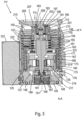
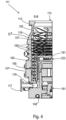
- FIGS. 1 to 5 show a known vacuum pump in the form of a turbomolecular vacuum pump 111, which according to the in connection with 6 described vacuum pump 111 according to the invention can be formed. Conversely, the following statements apply in connection with the Figures 1 to 5 also for the vacuum pump according to the invention 6 .
- the turbomolecular pump 111 shown comprises a pump inlet 115 surrounded by an inlet flange 113, to which a recipient, not shown, can be connected in a manner known per se.
- the gas from the recipient can be sucked out of the recipient via the pump inlet 115 and conveyed through the pump to a pump outlet 117 to which a backing pump, such as a rotary vane pump, can be connected.
- the inlet flange 113 forms when the vacuum pump is aligned according to FIG 1 the upper end of the housing 119 of the vacuum pump 111.
- the housing 119 comprises a lower part 121 on which an electronics housing 123 is arranged laterally. Electrical and/or electronic components of the vacuum pump 111 are accommodated in the electronics housing 123, for example for operating an electric motor 125 arranged in the vacuum pump (cf. also 3 ). Several connections 127 for accessories are provided on the electronics housing 123 .
- a data interface 129 for example according to the RS485 standard, and a power supply connection 131 are arranged on the electronics housing 123.
- turbomolecular pumps that do not have such an attached electronics housing, but are connected to external drive electronics.
- a flood inlet 133 in particular in the form of a flood valve, is provided on the housing 119 of the turbomolecular pump 111, via which the vacuum pump 111 can be flooded.
- a sealing gas connection 135, which is also referred to as a flushing gas connection through which flushing gas to protect the electric motor 125 (see e.g 3 ) before the pumped gas in the motor compartment 137, in which the electric motor 125 is housed in the vacuum pump 111, can be admitted.
- Two coolant connections 139 are also arranged in the lower part 121, one of the coolant connections being provided as an inlet and the other coolant connection being provided as an outlet for coolant, which can be conducted into the vacuum pump for cooling purposes.
- Other existing turbomolecular vacuum pumps (not shown) operate solely on air cooling.
- the lower side 141 of the vacuum pump can serve as a standing surface, so that the vacuum pump 111 can be operated standing on the underside 141 .
- the vacuum pump 111 can also be fastened to a recipient via the inlet flange 113 and can thus be operated in a suspended manner, as it were.
- the vacuum pump 111 can be designed in such a way that it can also be operated when it is oriented in a different way than in FIG 1 is shown. It is also possible to realize embodiments of the vacuum pump in which the underside 141 cannot be arranged facing downwards but to the side or directed upwards. In principle, any angles are possible.
- various screws 143 are also arranged, by means of which components of the vacuum pump that are not further specified here are fastened to one another.
- a bearing cap 145 is attached to the underside 141 .
- fastening bores 147 are arranged on the underside 141, via which the pump 111 can be fastened, for example, to a support surface. This is not possible with other existing turbomolecular vacuum pumps (not shown), which in particular are larger than the pump shown here.
- a coolant line 148 is shown, in which the coolant fed in and out via the coolant connections 139 can circulate.
- the vacuum pump comprises several process gas pump stages for conveying the process gas present at the pump inlet 115 to the pump outlet 117.
- a rotor 149 is arranged in the housing 119 and has a rotor shaft 153 which can be rotated about an axis of rotation 151 .
- the turbomolecular pump 111 comprises a plurality of turbomolecular pumping stages connected in series with one another in a pumping manner, with a plurality of radial rotor disks 155 fastened to the rotor shaft 153 and stator disks 157 arranged between the rotor disks 155 and fixed in the housing 119.
- a rotor disk 155 and an adjacent stator disk 157 each form a turbomolecular pump stage.
- the stator discs 157 are held at a desired axial distance from one another by spacer rings 159 .
- the vacuum pump also comprises Holweck pump stages which are arranged one inside the other in the radial direction and are connected in series with one another for pumping purposes.
- Other turbomolecular vacuum pumps (not shown) exist that do not have Holweck pumping stages.
- the rotor of the Holweck pump stages comprises a rotor hub 161 arranged on the rotor shaft 153 and two Holweck rotor sleeves 163, 165 in the shape of a cylinder jacket, fastened to the rotor hub 161 and carried by it, which are oriented coaxially to the axis of rotation 151 and are nested in one another in the radial direction. Also provided are two cylinder jacket-shaped Holweck stator sleeves 167, 169, which are also oriented coaxially with respect to the axis of rotation 151 and are nested in one another when viewed in the radial direction.
- the pumping-active surfaces of the Holweck pump stages are formed by the lateral surfaces, ie by the radial inner and/or outer surfaces, of the Holweck rotor sleeves 163, 165 and the Holweck stator sleeves 167, 169.
- the radially inner surface of the outer Holweck stator sleeve 167 faces the radially outer surface of the outer Holweck rotor sleeve 163 to form a radial Holweck gap 171 and forms with it the subsequent one of the turbomolecular pumps first Holweck pump stage.
- the radially inner surface of the outer Holweck rotor sleeve 163 faces the radially outer surface of the inner Holweck stator sleeve 169 to form a radial Holweck gap 173 and therewith forms a second Holweck pumping stage.
- the radially inner surface of the inner Holweck stator sleeve 169 faces the radially outer surface of the inner Holweck rotor sleeve 165 to form a radial Holweck gap 175 and therewith forms the third Holweck pumping stage.
- a radially running channel can be provided, via which the radially outer Holweck gap 171 is connected to the middle Holweck gap 173.
- a radially extending channel can be provided at the upper end of the inner Holweck stator sleeve 169, via which the middle Holweck gap 173 is connected to the radially inner Holweck gap 175.
- a connecting channel 179 to the outlet 117 can be provided at the lower end of the radially inner Holweck rotor sleeve 165 .
- the above-mentioned pumping-active surfaces of the Holweck stator sleeves 167, 169 each have a plurality of Holweck grooves running in a spiral shape around the axis of rotation 151 in the axial direction, while the opposite lateral surfaces of the Holweck rotor sleeves 163, 165 are smooth and the gas for operating the Advance vacuum pump 111 in the Holweck grooves.
- a roller bearing 181 in the region of the pump outlet 117 and a permanent magnet bearing 183 in the region of the pump inlet 115 are provided for the rotatable mounting of the rotor shaft 153 .
- injection nut 185 In the area of the roller bearing 181 there is a conical injection nut 185 on the rotor shaft 153 with an outer diameter which increases towards the roller bearing 181 intended.
- the injection nut 185 is in sliding contact with at least one stripper of an operating fluid store.
- an injection screw may be provided instead of an injection nut. Since different designs are thus possible, the term "spray tip" is also used in this context.
- the resource reservoir comprises a plurality of absorbent discs 187 stacked on top of one another, which are impregnated with a resource for the roller bearing 181, e.g. with a lubricant.
- the operating fluid is transferred by capillary action from the operating fluid reservoir via the scraper to the rotating spray nut 185 and, as a result of the centrifugal force, is conveyed along the spray nut 185 in the direction of the increasing outer diameter of the spray nut 185 to the roller bearing 181, where it e.g. fulfills a lubricating function.
- the roller bearing 181 and the operating fluid reservoir are surrounded by a trough-shaped insert 189 and the bearing cover 145 in the vacuum pump.
- the permanent magnet bearing 183 comprises a bearing half 191 on the rotor side and a bearing half 193 on the stator side, which each comprise a ring stack of a plurality of permanent magnetic rings 195, 197 stacked on top of one another in the axial direction.
- the ring magnets 195, 197 lie opposite one another, forming a radial bearing gap 199, the ring magnets 195 on the rotor side being arranged radially on the outside and the ring magnets 197 on the stator side being arranged radially on the inside.
- the magnetic field present in the bearing gap 199 produces magnetic repulsive forces between the ring magnets 195, 197, which cause the rotor shaft 153 to be supported radially.
- the ring magnets 195 on the rotor side are carried by a support section 201 of the rotor shaft 153, which radially surrounds the ring magnets 195 on the outside.
- the ring magnets 197 on the stator side are carried by a support portion 203 on the stator side, which extends through extends through ring magnets 197 and is suspended from radial struts 205 of housing 119.
- the ring magnets 195 on the rotor side are fixed parallel to the axis of rotation 151 by a cover element 207 coupled to the carrier section 201 .
- the stator-side ring magnets 197 are fixed parallel to the axis of rotation 151 in one direction by a fastening ring 209 connected to the support section 203 and a fastening ring 211 connected to the support section 203 .
- a disc spring 213 can also be provided between the fastening ring 211 and the ring magnet 197 .
- An emergency or safety bearing 215 is provided within the magnetic bearing, which runs idle without contact during normal operation of the vacuum pump 111 and only engages in the event of an excessive radial deflection of the rotor 149 relative to the stator, in order to create a radial stop for the rotor 149 to form, so that a collision of the rotor-side structures is prevented with the stator-side structures.
- the backup bearing 215 is designed as an unlubricated roller bearing and forms a radial gap with the rotor 149 and/or the stator, which causes the backup bearing 215 to be disengaged during normal pumping operation.
- the radial deflection at which the backup bearing 215 engages is dimensioned large enough so that the backup bearing 215 does not engage during normal operation of the vacuum pump, and at the same time small enough so that the rotor-side structures collide with the stator-side structures under all circumstances is prevented.
- the vacuum pump 111 includes the electric motor 125 as a drive for rotating the rotor 149.
- the armature of the electric motor 125 is formed by the rotor 149, the rotor shaft 153 of which extends through the motor stator 217.
- a permanent magnet arrangement can be arranged radially on the outside or embedded on the section of the rotor shaft 153 that extends through the motor stator 217 .
- an intermediate space 219 is arranged, which comprises a radial motor gap, via which the motor stator 217 and the permanent magnet arrangement can affect one another magnetically in order to transmit the drive torque.
- the motor stator 217 is fixed in the housing inside the motor room 137 provided for the electric motor 125 .
- a sealing gas which is also referred to as flushing gas and which can be air or nitrogen, for example, can get into the engine compartment 137 via the sealing gas connection 135 .
- the sealing gas can protect the electric motor 125 from process gas, e.g. from corrosive components of the process gas.
- the engine compartment 137 can also be evacuated via the pump outlet 117, i.e. the vacuum pressure produced by the backing pump connected to the pump outlet 117 prevails in the engine compartment 137 at least approximately.
- a labyrinth seal 223 can also be provided between the rotor hub 161 and a wall 221 delimiting the motor compartment 137, in particular in order to achieve better sealing of the motor compartment 217 in relation to the Holweck pump stages located radially outside.
- heat can be generated in the vacuum pump 111, for example due to friction in the roller bearing 181, due to eddy currents induced by a magnetic field in the rotor 149 or due to waste heat from electrical components.
- the temperature on the outer surface 227 of the pump housing 119 can increase to such an extent that there is a risk of burns if the pump housing 119 comes into contact.
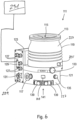
- a sensor 225 is used to determine the outer surface temperature 6
- two possible mounting locations for the sensor 225 are shown purely by way of example.
- the sensor 225 can be attached to the outer surface 227 of the pump housing 119 or also to the outer surface 227 of the lower part 121 .
- the temperature on the outer surface 227 of the pump 111 can also be inferred indirectly by measuring the temperature elsewhere, as already mentioned in the introductory part.
- control unit 229 connected to the sensor 225 and housed - in principle at any desired point and here purely by way of example in the electronics housing 123 - which, depending on the value of the 225 determined temperature takes one or more protective measures, as explained in the introductory part using different examples, when the control unit 229 is in protection mode.
- a user interface 231 shown only schematically in the form of a mobile terminal device, e.g. a notebook, is provided, via which the user can interact with the control unit 229, e.g. in which the control unit 229 takes no protective action.
- the user interface 231 can be connected to the control unit 229 via the data interface 129, for example. Alternatively, wireless communication is also possible.
- the user interface 231 serves not only to switch between the protection mode and the neutral mode, but also to change the default.
- a change in the specification can include an increase or decrease in a safety temperature.
- the safety temperature can be increased from 60° C. to 80° C. if the vacuum pump 111 is surrounded by a protection against accidental contact, which excludes direct contact with the outer surface of the pump housing by operating personnel or makes it less likely.
- the safety temperature can be reduced, for example to 40°C.
- changing the specification can also include changing the protective measure.
- a warning signal can be output as a protective measure.
- Such a setting can be provided, for example, in the case of vacuum pumps 111 that are built in to be protected against accidental contact, if the pump output does not need to be restricted. However, the user is warned that the temperature of the pump housing 119 is above the safety temperature, so that the user can take appropriate safety precautions when approaching the vacuum pump 111 .
- a change in the specification can also include a change in the association between different values of the determined temperature—generally the respective operating parameter of the vacuum pump—and different protective measures.
- a warning signal is issued when a temperature below a safety temperature of 60° C. is reached, for example when 50° C. is reached, and the rotor speed is reduced when the safety temperature is reached or exceeded.
- the user can change this assignment yourself. For example, he can adapt the specification so that when the safety temperature of 60°C is reached or exceeded, a warning signal is issued for the first time and another protective measure is only taken at a temperature above the safety temperature, such as switching off the vacuum pump 111 if the temperature on the outer surface of the housing exceeds 80°C.
- a vacuum pump 111 that is initially installed with protection against contact and is therefore operated in a neutral mode can also be switched back from the neutral mode to the protection mode by a user via the user interface 231 if, for example, the installation location has to be changed and a protection against contact is no longer available can be ensured.
- the vacuum pump 111 can then be operated with those operating parameters which are maximally possible within the framework of user protection.
- the potential of the vacuum pump 111 can therefore always be optimally utilized depending on the respective usage environment.
Landscapes
- Engineering & Computer Science (AREA)
- Mechanical Engineering (AREA)
- General Engineering & Computer Science (AREA)
- Non-Positive Displacement Air Blowers (AREA)
Priority Applications (2)
| Application Number | Priority Date | Filing Date | Title |
|---|---|---|---|
| EP21205430.8A EP4174321B1 (fr) | 2021-10-29 | 2021-10-29 | Pompe à vide |
| JP2022101735A JP7483797B2 (ja) | 2021-10-29 | 2022-06-24 | 真空ポンプ |
Applications Claiming Priority (1)
| Application Number | Priority Date | Filing Date | Title |
|---|---|---|---|
| EP21205430.8A EP4174321B1 (fr) | 2021-10-29 | 2021-10-29 | Pompe à vide |
Publications (2)
| Publication Number | Publication Date |
|---|---|
| EP4174321A1 true EP4174321A1 (fr) | 2023-05-03 |
| EP4174321B1 EP4174321B1 (fr) | 2024-01-17 |
Family
ID=78414442
Family Applications (1)
| Application Number | Title | Priority Date | Filing Date |
|---|---|---|---|
| EP21205430.8A Active EP4174321B1 (fr) | 2021-10-29 | 2021-10-29 | Pompe à vide |
Country Status (2)
| Country | Link |
|---|---|
| EP (1) | EP4174321B1 (fr) |
| JP (1) | JP7483797B2 (fr) |
Citations (3)
| Publication number | Priority date | Publication date | Assignee | Title |
|---|---|---|---|---|
| EP1898098A2 (fr) * | 2006-09-01 | 2008-03-12 | Oerlikon Leybold Vacuum GmbH | Pompe à vide |
| EP3557072A1 (fr) * | 2019-02-27 | 2019-10-23 | Pfeiffer Vacuum Gmbh | Surveillance d'un dispositif de palier d'une pompe à vide |
| EP3620662A1 (fr) * | 2018-09-06 | 2020-03-11 | Pfeiffer Vacuum Gmbh | Appareil utilisateur pour un dispositif à vide |
Family Cites Families (3)
| Publication number | Priority date | Publication date | Assignee | Title |
|---|---|---|---|---|
| US7021027B2 (en) * | 2003-07-29 | 2006-04-04 | Tilia International, Inc. | Vacuum pump control and vacuum feedback |
| JP5565367B2 (ja) * | 2011-04-11 | 2014-08-06 | 株式会社島津製作所 | 真空ポンプ |
| JP5765177B2 (ja) * | 2011-10-04 | 2015-08-19 | 株式会社島津製作所 | 電源一体型真空ポンプ |
-
2021
- 2021-10-29 EP EP21205430.8A patent/EP4174321B1/fr active Active
-
2022
- 2022-06-24 JP JP2022101735A patent/JP7483797B2/ja active Active
Patent Citations (3)
| Publication number | Priority date | Publication date | Assignee | Title |
|---|---|---|---|---|
| EP1898098A2 (fr) * | 2006-09-01 | 2008-03-12 | Oerlikon Leybold Vacuum GmbH | Pompe à vide |
| EP3620662A1 (fr) * | 2018-09-06 | 2020-03-11 | Pfeiffer Vacuum Gmbh | Appareil utilisateur pour un dispositif à vide |
| EP3557072A1 (fr) * | 2019-02-27 | 2019-10-23 | Pfeiffer Vacuum Gmbh | Surveillance d'un dispositif de palier d'une pompe à vide |
Also Published As
| Publication number | Publication date |
|---|---|
| EP4174321B1 (fr) | 2024-01-17 |
| JP7483797B2 (ja) | 2024-05-15 |
| JP2023067727A (ja) | 2023-05-16 |
Similar Documents
| Publication | Publication Date | Title |
|---|---|---|
| EP2826999B1 (fr) | Pompe à vide | |
| EP3657021B1 (fr) | Pompe à vide | |
| EP3112687B1 (fr) | Détection de la circulation d'un gaz auxiliaire qui est injecté dans une pompe à vide | |
| EP4174321B1 (fr) | Pompe à vide | |
| EP3683449B1 (fr) | Palier magnétique et appareil sous vide | |
| EP3660317A1 (fr) | Appareil à vide | |
| EP3135932B2 (fr) | Pompe a vide et palier a aimant permanent | |
| EP3473858B1 (fr) | Procédé d'optimisation de durée de vie des paliers à rouleaux d'une pompe à vide | |
| EP3557072B1 (fr) | Surveillance d'un dispositif de palier d'une pompe à vide | |
| EP4212730A1 (fr) | Pompe à vide avec étage de pompage de holward optimisé pour compenser la perte de performance liée à la température | |
| EP4194700B1 (fr) | Pompe à vide avec étage de pompe de holweck à géométrie de holweck variable | |
| EP3536965B1 (fr) | Pompe à vide dans laquelle le support d'un palier à roulement a une rigidité et/ou un amortissement réglable(s) | |
| EP3907406B1 (fr) | Pompe à vide | |
| DE102020116770B4 (de) | Vakuumpumpe mit integriertem miniaturventil | |
| EP3926174B1 (fr) | Pompe à vide | |
| EP2927501B1 (fr) | Procédé et système pour la détermination et l'évaluation du sens d'encastrement d'un dispositif | |
| EP3536966B1 (fr) | Appareil à vide | |
| EP3575610B1 (fr) | Pompe à vide avec réservoir de lubrifiant | |
| EP3760872A1 (fr) | Pompe à vide pourvue d'un agencement de fixation destiné à l'application de la pompe à une structure de fixation ainsi qu'un poste de pompage doté d'une telle pompe à vide montée sur celui-ci | |
| EP3557071B1 (fr) | Pompe à vide et procédé de fonctionnement d'une telle pompe à vide | |
| EP3339651B1 (fr) | Pompe à vide | |
| EP4137699B1 (fr) | Appareil à vide et procédé de fonctionnement d'un tel appareil à vide | |
| EP4293232B1 (fr) | Pompe turbomoléculaire | |
| EP3628883B1 (fr) | Pompe à vide | |
| EP3708843B1 (fr) | Procédé de fabrication d'un moteur électrique ou d'un appareil a vide avec un tel moteur |
Legal Events
| Date | Code | Title | Description |
|---|---|---|---|
| PUAI | Public reference made under article 153(3) epc to a published international application that has entered the european phase |
Free format text: ORIGINAL CODE: 0009012 |
|
| STAA | Information on the status of an ep patent application or granted ep patent |
Free format text: STATUS: THE APPLICATION HAS BEEN PUBLISHED |
|
| AK | Designated contracting states |
Kind code of ref document: A1 Designated state(s): AL AT BE BG CH CY CZ DE DK EE ES FI FR GB GR HR HU IE IS IT LI LT LU LV MC MK MT NL NO PL PT RO RS SE SI SK SM TR |
|
| STAA | Information on the status of an ep patent application or granted ep patent |
Free format text: STATUS: REQUEST FOR EXAMINATION WAS MADE |
|
| 17P | Request for examination filed |
Effective date: 20230510 |
|
| RBV | Designated contracting states (corrected) |
Designated state(s): AL AT BE BG CH CY CZ DE DK EE ES FI FR GB GR HR HU IE IS IT LI LT LU LV MC MK MT NL NO PL PT RO RS SE SI SK SM TR |
|
| STAA | Information on the status of an ep patent application or granted ep patent |
Free format text: STATUS: EXAMINATION IS IN PROGRESS |
|
| 17Q | First examination report despatched |
Effective date: 20230704 |
|
| GRAP | Despatch of communication of intention to grant a patent |
Free format text: ORIGINAL CODE: EPIDOSNIGR1 |
|
| STAA | Information on the status of an ep patent application or granted ep patent |
Free format text: STATUS: GRANT OF PATENT IS INTENDED |
|
| INTG | Intention to grant announced |
Effective date: 20231016 |
|
| GRAS | Grant fee paid |
Free format text: ORIGINAL CODE: EPIDOSNIGR3 |
|
| GRAA | (expected) grant |
Free format text: ORIGINAL CODE: 0009210 |
|
| STAA | Information on the status of an ep patent application or granted ep patent |
Free format text: STATUS: THE PATENT HAS BEEN GRANTED |
|
| AK | Designated contracting states |
Kind code of ref document: B1 Designated state(s): AL AT BE BG CH CY CZ DE DK EE ES FI FR GB GR HR HU IE IS IT LI LT LU LV MC MK MT NL NO PL PT RO RS SE SI SK SM TR |
|
| REG | Reference to a national code |
Ref country code: GB Ref legal event code: FG4D Free format text: NOT ENGLISH |
|
| REG | Reference to a national code |
Ref country code: DE Ref legal event code: R096 Ref document number: 502021002482 Country of ref document: DE |
|
| REG | Reference to a national code |
Ref country code: CH Ref legal event code: EP |
|
| REG | Reference to a national code |
Ref country code: IE Ref legal event code: FG4D Free format text: LANGUAGE OF EP DOCUMENT: GERMAN |
|
| REG | Reference to a national code |
Ref country code: LT Ref legal event code: MG9D |
|
| REG | Reference to a national code |
Ref country code: NL Ref legal event code: MP Effective date: 20240117 |
|
| PG25 | Lapsed in a contracting state [announced via postgrant information from national office to epo] |
Ref country code: NL Free format text: LAPSE BECAUSE OF FAILURE TO SUBMIT A TRANSLATION OF THE DESCRIPTION OR TO PAY THE FEE WITHIN THE PRESCRIBED TIME-LIMIT Effective date: 20240117 |
|
| PG25 | Lapsed in a contracting state [announced via postgrant information from national office to epo] |
Ref country code: NL Free format text: LAPSE BECAUSE OF FAILURE TO SUBMIT A TRANSLATION OF THE DESCRIPTION OR TO PAY THE FEE WITHIN THE PRESCRIBED TIME-LIMIT Effective date: 20240117 |
|
| PG25 | Lapsed in a contracting state [announced via postgrant information from national office to epo] |
Ref country code: IS Free format text: LAPSE BECAUSE OF FAILURE TO SUBMIT A TRANSLATION OF THE DESCRIPTION OR TO PAY THE FEE WITHIN THE PRESCRIBED TIME-LIMIT Effective date: 20240517 |
|
| PG25 | Lapsed in a contracting state [announced via postgrant information from national office to epo] |
Ref country code: LT Free format text: LAPSE BECAUSE OF FAILURE TO SUBMIT A TRANSLATION OF THE DESCRIPTION OR TO PAY THE FEE WITHIN THE PRESCRIBED TIME-LIMIT Effective date: 20240117 |
|
| PG25 | Lapsed in a contracting state [announced via postgrant information from national office to epo] |
Ref country code: GR Free format text: LAPSE BECAUSE OF FAILURE TO SUBMIT A TRANSLATION OF THE DESCRIPTION OR TO PAY THE FEE WITHIN THE PRESCRIBED TIME-LIMIT Effective date: 20240418 |
|
| PG25 | Lapsed in a contracting state [announced via postgrant information from national office to epo] |
Ref country code: HR Free format text: LAPSE BECAUSE OF FAILURE TO SUBMIT A TRANSLATION OF THE DESCRIPTION OR TO PAY THE FEE WITHIN THE PRESCRIBED TIME-LIMIT Effective date: 20240117 Ref country code: RS Free format text: LAPSE BECAUSE OF FAILURE TO SUBMIT A TRANSLATION OF THE DESCRIPTION OR TO PAY THE FEE WITHIN THE PRESCRIBED TIME-LIMIT Effective date: 20240417 |
|
| PG25 | Lapsed in a contracting state [announced via postgrant information from national office to epo] |
Ref country code: ES Free format text: LAPSE BECAUSE OF FAILURE TO SUBMIT A TRANSLATION OF THE DESCRIPTION OR TO PAY THE FEE WITHIN THE PRESCRIBED TIME-LIMIT Effective date: 20240117 |
|
| PG25 | Lapsed in a contracting state [announced via postgrant information from national office to epo] |
Ref country code: RS Free format text: LAPSE BECAUSE OF FAILURE TO SUBMIT A TRANSLATION OF THE DESCRIPTION OR TO PAY THE FEE WITHIN THE PRESCRIBED TIME-LIMIT Effective date: 20240417 Ref country code: NO Free format text: LAPSE BECAUSE OF FAILURE TO SUBMIT A TRANSLATION OF THE DESCRIPTION OR TO PAY THE FEE WITHIN THE PRESCRIBED TIME-LIMIT Effective date: 20240417 Ref country code: LT Free format text: LAPSE BECAUSE OF FAILURE TO SUBMIT A TRANSLATION OF THE DESCRIPTION OR TO PAY THE FEE WITHIN THE PRESCRIBED TIME-LIMIT Effective date: 20240117 Ref country code: IS Free format text: LAPSE BECAUSE OF FAILURE TO SUBMIT A TRANSLATION OF THE DESCRIPTION OR TO PAY THE FEE WITHIN THE PRESCRIBED TIME-LIMIT Effective date: 20240517 Ref country code: HR Free format text: LAPSE BECAUSE OF FAILURE TO SUBMIT A TRANSLATION OF THE DESCRIPTION OR TO PAY THE FEE WITHIN THE PRESCRIBED TIME-LIMIT Effective date: 20240117 Ref country code: GR Free format text: LAPSE BECAUSE OF FAILURE TO SUBMIT A TRANSLATION OF THE DESCRIPTION OR TO PAY THE FEE WITHIN THE PRESCRIBED TIME-LIMIT Effective date: 20240418 Ref country code: FI Free format text: LAPSE BECAUSE OF FAILURE TO SUBMIT A TRANSLATION OF THE DESCRIPTION OR TO PAY THE FEE WITHIN THE PRESCRIBED TIME-LIMIT Effective date: 20240117 Ref country code: ES Free format text: LAPSE BECAUSE OF FAILURE TO SUBMIT A TRANSLATION OF THE DESCRIPTION OR TO PAY THE FEE WITHIN THE PRESCRIBED TIME-LIMIT Effective date: 20240117 Ref country code: BG Free format text: LAPSE BECAUSE OF FAILURE TO SUBMIT A TRANSLATION OF THE DESCRIPTION OR TO PAY THE FEE WITHIN THE PRESCRIBED TIME-LIMIT Effective date: 20240117 |
|
| PG25 | Lapsed in a contracting state [announced via postgrant information from national office to epo] |
Ref country code: PT Free format text: LAPSE BECAUSE OF FAILURE TO SUBMIT A TRANSLATION OF THE DESCRIPTION OR TO PAY THE FEE WITHIN THE PRESCRIBED TIME-LIMIT Effective date: 20240517 Ref country code: PL Free format text: LAPSE BECAUSE OF FAILURE TO SUBMIT A TRANSLATION OF THE DESCRIPTION OR TO PAY THE FEE WITHIN THE PRESCRIBED TIME-LIMIT Effective date: 20240117 |
|
| PG25 | Lapsed in a contracting state [announced via postgrant information from national office to epo] |
Ref country code: SE Free format text: LAPSE BECAUSE OF FAILURE TO SUBMIT A TRANSLATION OF THE DESCRIPTION OR TO PAY THE FEE WITHIN THE PRESCRIBED TIME-LIMIT Effective date: 20240117 Ref country code: PT Free format text: LAPSE BECAUSE OF FAILURE TO SUBMIT A TRANSLATION OF THE DESCRIPTION OR TO PAY THE FEE WITHIN THE PRESCRIBED TIME-LIMIT Effective date: 20240517 Ref country code: PL Free format text: LAPSE BECAUSE OF FAILURE TO SUBMIT A TRANSLATION OF THE DESCRIPTION OR TO PAY THE FEE WITHIN THE PRESCRIBED TIME-LIMIT Effective date: 20240117 Ref country code: LV Free format text: LAPSE BECAUSE OF FAILURE TO SUBMIT A TRANSLATION OF THE DESCRIPTION OR TO PAY THE FEE WITHIN THE PRESCRIBED TIME-LIMIT Effective date: 20240117 |
|
| PG25 | Lapsed in a contracting state [announced via postgrant information from national office to epo] |
Ref country code: DK Free format text: LAPSE BECAUSE OF FAILURE TO SUBMIT A TRANSLATION OF THE DESCRIPTION OR TO PAY THE FEE WITHIN THE PRESCRIBED TIME-LIMIT Effective date: 20240117 |
|
| PG25 | Lapsed in a contracting state [announced via postgrant information from national office to epo] |
Ref country code: SM Free format text: LAPSE BECAUSE OF FAILURE TO SUBMIT A TRANSLATION OF THE DESCRIPTION OR TO PAY THE FEE WITHIN THE PRESCRIBED TIME-LIMIT Effective date: 20240117 |
|
| REG | Reference to a national code |
Ref country code: DE Ref legal event code: R097 Ref document number: 502021002482 Country of ref document: DE |
|
| PG25 | Lapsed in a contracting state [announced via postgrant information from national office to epo] |
Ref country code: EE Free format text: LAPSE BECAUSE OF FAILURE TO SUBMIT A TRANSLATION OF THE DESCRIPTION OR TO PAY THE FEE WITHIN THE PRESCRIBED TIME-LIMIT Effective date: 20240117 |
|
| PG25 | Lapsed in a contracting state [announced via postgrant information from national office to epo] |
Ref country code: SK Free format text: LAPSE BECAUSE OF FAILURE TO SUBMIT A TRANSLATION OF THE DESCRIPTION OR TO PAY THE FEE WITHIN THE PRESCRIBED TIME-LIMIT Effective date: 20240117 |
|
| PG25 | Lapsed in a contracting state [announced via postgrant information from national office to epo] |
Ref country code: SM Free format text: LAPSE BECAUSE OF FAILURE TO SUBMIT A TRANSLATION OF THE DESCRIPTION OR TO PAY THE FEE WITHIN THE PRESCRIBED TIME-LIMIT Effective date: 20240117 Ref country code: SK Free format text: LAPSE BECAUSE OF FAILURE TO SUBMIT A TRANSLATION OF THE DESCRIPTION OR TO PAY THE FEE WITHIN THE PRESCRIBED TIME-LIMIT Effective date: 20240117 Ref country code: RO Free format text: LAPSE BECAUSE OF FAILURE TO SUBMIT A TRANSLATION OF THE DESCRIPTION OR TO PAY THE FEE WITHIN THE PRESCRIBED TIME-LIMIT Effective date: 20240117 Ref country code: EE Free format text: LAPSE BECAUSE OF FAILURE TO SUBMIT A TRANSLATION OF THE DESCRIPTION OR TO PAY THE FEE WITHIN THE PRESCRIBED TIME-LIMIT Effective date: 20240117 Ref country code: DK Free format text: LAPSE BECAUSE OF FAILURE TO SUBMIT A TRANSLATION OF THE DESCRIPTION OR TO PAY THE FEE WITHIN THE PRESCRIBED TIME-LIMIT Effective date: 20240117 |
|
| PLBE | No opposition filed within time limit |
Free format text: ORIGINAL CODE: 0009261 |
|
| STAA | Information on the status of an ep patent application or granted ep patent |
Free format text: STATUS: NO OPPOSITION FILED WITHIN TIME LIMIT |
|
| 26N | No opposition filed |
Effective date: 20241018 |
|
| PG25 | Lapsed in a contracting state [announced via postgrant information from national office to epo] |
Ref country code: SI Free format text: LAPSE BECAUSE OF FAILURE TO SUBMIT A TRANSLATION OF THE DESCRIPTION OR TO PAY THE FEE WITHIN THE PRESCRIBED TIME-LIMIT Effective date: 20240117 |
|
| REG | Reference to a national code |
Ref country code: CH Ref legal event code: PL |
|
| PG25 | Lapsed in a contracting state [announced via postgrant information from national office to epo] |
Ref country code: MC Free format text: LAPSE BECAUSE OF FAILURE TO SUBMIT A TRANSLATION OF THE DESCRIPTION OR TO PAY THE FEE WITHIN THE PRESCRIBED TIME-LIMIT Effective date: 20240117 |
|
| PG25 | Lapsed in a contracting state [announced via postgrant information from national office to epo] |
Ref country code: LU Free format text: LAPSE BECAUSE OF NON-PAYMENT OF DUE FEES Effective date: 20241029 Ref country code: BE Free format text: LAPSE BECAUSE OF NON-PAYMENT OF DUE FEES Effective date: 20241031 |
|
| PG25 | Lapsed in a contracting state [announced via postgrant information from national office to epo] |
Ref country code: FR Free format text: LAPSE BECAUSE OF NON-PAYMENT OF DUE FEES Effective date: 20241031 |
|
| PG25 | Lapsed in a contracting state [announced via postgrant information from national office to epo] |
Ref country code: CH Free format text: LAPSE BECAUSE OF NON-PAYMENT OF DUE FEES Effective date: 20241031 |
|
| REG | Reference to a national code |
Ref country code: BE Ref legal event code: MM Effective date: 20241031 |
|
| PG25 | Lapsed in a contracting state [announced via postgrant information from national office to epo] |
Ref country code: IE Free format text: LAPSE BECAUSE OF NON-PAYMENT OF DUE FEES Effective date: 20241029 |
|
| PGFP | Annual fee paid to national office [announced via postgrant information from national office to epo] |
Ref country code: GB Payment date: 20251022 Year of fee payment: 5 |
|
| PGFP | Annual fee paid to national office [announced via postgrant information from national office to epo] |
Ref country code: AT Payment date: 20260113 Year of fee payment: 5 |
|
| PGFP | Annual fee paid to national office [announced via postgrant information from national office to epo] |
Ref country code: IT Payment date: 20251024 Year of fee payment: 5 |
|
| PGFP | Annual fee paid to national office [announced via postgrant information from national office to epo] |
Ref country code: CZ Payment date: 20251021 Year of fee payment: 5 |
|
| PG25 | Lapsed in a contracting state [announced via postgrant information from national office to epo] |
Ref country code: HU Free format text: LAPSE BECAUSE OF FAILURE TO SUBMIT A TRANSLATION OF THE DESCRIPTION OR TO PAY THE FEE WITHIN THE PRESCRIBED TIME-LIMIT; INVALID AB INITIO Effective date: 20211029 |
|
| PG25 | Lapsed in a contracting state [announced via postgrant information from national office to epo] |
Ref country code: CY Free format text: LAPSE BECAUSE OF FAILURE TO SUBMIT A TRANSLATION OF THE DESCRIPTION OR TO PAY THE FEE WITHIN THE PRESCRIBED TIME-LIMIT; INVALID AB INITIO Effective date: 20211029 |
|
| PGFP | Annual fee paid to national office [announced via postgrant information from national office to epo] |
Ref country code: DE Payment date: 20251229 Year of fee payment: 5 |