EP4222155B1 - Mononukleare tripodale hexadentate iridium komplexe zur verwendung in oleds - Google Patents
Mononukleare tripodale hexadentate iridium komplexe zur verwendung in oleds Download PDFInfo
- Publication number
- EP4222155B1 EP4222155B1 EP21782984.5A EP21782984A EP4222155B1 EP 4222155 B1 EP4222155 B1 EP 4222155B1 EP 21782984 A EP21782984 A EP 21782984A EP 4222155 B1 EP4222155 B1 EP 4222155B1
- Authority
- EP
- European Patent Office
- Prior art keywords
- optionally
- alkyl group
- carbon atoms
- group
- deuterated
- Prior art date
- Legal status (The legal status is an assumption and is not a legal conclusion. Google has not performed a legal analysis and makes no representation as to the accuracy of the status listed.)
- Active
Links
Classifications
-
- C—CHEMISTRY; METALLURGY
- C07—ORGANIC CHEMISTRY
- C07F—ACYCLIC, CARBOCYCLIC OR HETEROCYCLIC COMPOUNDS CONTAINING ELEMENTS OTHER THAN CARBON, HYDROGEN, HALOGEN, OXYGEN, NITROGEN, SULFUR, SELENIUM OR TELLURIUM
- C07F15/00—Compounds containing elements of Groups 8, 9, 10 or 18 of the Periodic Table
- C07F15/0006—Compounds containing elements of Groups 8, 9, 10 or 18 of the Periodic Table compounds of the platinum group
- C07F15/0033—Iridium compounds
-
- C—CHEMISTRY; METALLURGY
- C09—DYES; PAINTS; POLISHES; NATURAL RESINS; ADHESIVES; COMPOSITIONS NOT OTHERWISE PROVIDED FOR; APPLICATIONS OF MATERIALS NOT OTHERWISE PROVIDED FOR
- C09K—MATERIALS FOR MISCELLANEOUS APPLICATIONS, NOT PROVIDED FOR ELSEWHERE
- C09K11/00—Luminescent materials, e.g. electroluminescent or chemiluminescent
- C09K11/06—Luminescent materials, e.g. electroluminescent or chemiluminescent containing organic luminescent materials
-
- H—ELECTRICITY
- H10—SEMICONDUCTOR DEVICES; ELECTRIC SOLID-STATE DEVICES NOT OTHERWISE PROVIDED FOR
- H10K—ORGANIC ELECTRIC SOLID-STATE DEVICES
- H10K50/00—Organic light-emitting devices
- H10K50/10—OLEDs or polymer light-emitting diodes [PLED]
- H10K50/11—OLEDs or polymer light-emitting diodes [PLED] characterised by the electroluminescent [EL] layers
- H10K50/12—OLEDs or polymer light-emitting diodes [PLED] characterised by the electroluminescent [EL] layers comprising dopants
-
- H—ELECTRICITY
- H10—SEMICONDUCTOR DEVICES; ELECTRIC SOLID-STATE DEVICES NOT OTHERWISE PROVIDED FOR
- H10K—ORGANIC ELECTRIC SOLID-STATE DEVICES
- H10K85/00—Organic materials used in the body or electrodes of devices covered by this subclass
-
- H—ELECTRICITY
- H10—SEMICONDUCTOR DEVICES; ELECTRIC SOLID-STATE DEVICES NOT OTHERWISE PROVIDED FOR
- H10K—ORGANIC ELECTRIC SOLID-STATE DEVICES
- H10K85/00—Organic materials used in the body or electrodes of devices covered by this subclass
- H10K85/30—Coordination compounds
- H10K85/341—Transition metal complexes, e.g. Ru(II)polypyridine complexes
- H10K85/342—Transition metal complexes, e.g. Ru(II)polypyridine complexes comprising iridium
-
- C—CHEMISTRY; METALLURGY
- C09—DYES; PAINTS; POLISHES; NATURAL RESINS; ADHESIVES; COMPOSITIONS NOT OTHERWISE PROVIDED FOR; APPLICATIONS OF MATERIALS NOT OTHERWISE PROVIDED FOR
- C09K—MATERIALS FOR MISCELLANEOUS APPLICATIONS, NOT PROVIDED FOR ELSEWHERE
- C09K2211/00—Chemical nature of organic luminescent or tenebrescent compounds
- C09K2211/10—Non-macromolecular compounds
- C09K2211/1018—Heterocyclic compounds
- C09K2211/1025—Heterocyclic compounds characterised by ligands
- C09K2211/1029—Heterocyclic compounds characterised by ligands containing one nitrogen atom as the heteroatom
-
- C—CHEMISTRY; METALLURGY
- C09—DYES; PAINTS; POLISHES; NATURAL RESINS; ADHESIVES; COMPOSITIONS NOT OTHERWISE PROVIDED FOR; APPLICATIONS OF MATERIALS NOT OTHERWISE PROVIDED FOR
- C09K—MATERIALS FOR MISCELLANEOUS APPLICATIONS, NOT PROVIDED FOR ELSEWHERE
- C09K2211/00—Chemical nature of organic luminescent or tenebrescent compounds
- C09K2211/18—Metal complexes
- C09K2211/185—Metal complexes of the platinum group, i.e. Os, Ir, Pt, Ru, Rh or Pd
Definitions
- the present invention relates to iridium complexes which are suitable for use in organic electroluminescent devices, in particular as emitters.
- Such complexes are also known with polypodal ligands, for example in US 7,332,232 , WO 2016/124304 and WO 2019/158453 Although these complexes with polypodal ligands show advantages over complexes that otherwise have the same ligand structure but whose individual ligands are not polypodally bridged, there is still room for improvement, for example, with regard to efficiency, voltage, and lifetime.
- the object of the present invention is therefore to provide improved iridium complexes which are suitable as emitters for use in OLEDs.
- iridium complexes with a hexadentate tripodal ligand having the structure described below solve this problem and are highly suitable for use in an organic electroluminescent device.
- These iridium complexes and organic electroluminescent devices containing these complexes are therefore the subject of the present invention.
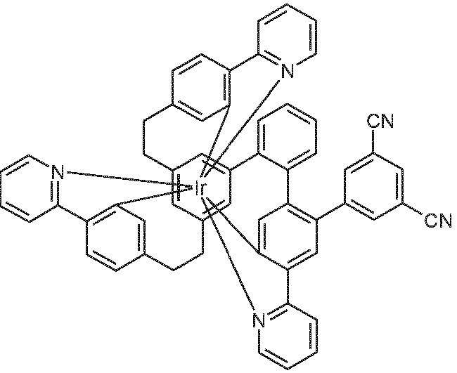
- the ligand L of formula (2) is thus a hexadentate, tripodal ligand with the three bidentate phenylpyridine subligands.
- the complex Ir(L) of formula (1) formed with this ligand thus has the following structure: where the symbols and indices have the meanings given above.
- two R radicals, or two R 1 radicals, or two R 2 radicals form a ring system
- this can be monocyclic or polycyclic.
- the radicals forming a ring system are adjacent, meaning that these radicals bond to carbon atoms that are directly bonded to one another.
- the phrase "two R radicals can form a ring” is understood to mean, among other things, that the two radicals are linked by a chemical bond with the formal elimination of two hydrogen atoms. This is illustrated by the following scheme:
- a cyclic alkyl group in the sense of this invention is understood to mean a monocyclic, a bicyclic or a polycyclic group.
- a C 1 to C 10 alkyl group includes, for example, the radicals methyl, ethyl, n-propyl, i-propyl, cyclopropyl, n-butyl, i-butyl, s-butyl, t-butyl, cyclobutyl, 2-methylbutyl, n-pentyl, s-pentyl, t-pentyl, 2-pentyl, neo-Pentyl, Cyclopentyl, n-Hexyl, s-Hexyl, t-Hexyl, 2-Hexyl, 3-Hexyl, neo-Hexyl, Cyclohexyl, 1-Methylcyclopentyl, 2-Methylpentyl, n-Heptyl, 2-Heptyl, 3-Heptyl, 4-Heptyl, Cycloheptyl, 1-Methylcyclopentyl
- n, p, q or r a hydrogen or deuterium atom is bonded to the corresponding phenyl or pyridine group instead of the corresponding substituents.
- the ligand L has a structure of the following formula (7), where the symbols and indices have the meanings given above and the hydrogen atoms not explicitly shown can also be replaced by deuterium.
- the substituents R are the same or different on each occurrence and are selected from the group consisting of D, a linear alkyl group having 1 to 6 C atoms, or a branched or cyclic alkyl group having 3 to 6 C atoms, where the alkyl groups may also be deuterated.
- the substituents R are the same or different on each occurrence and are selected from the group consisting of D, a linear alkyl group having 1 to 4 C atoms, or a branched alkyl group having 3 or 4 C atoms, where the alkyl groups may also be deuterated.
- R is particularly preferably a methyl group or a CD 3 group.
- the substituents R 1 are, identically or differently on each occurrence, selected from the group consisting of D, a linear alkyl group having 1 to 6 C atoms or a branched or cyclic alkyl group having 3 to 6 C atoms, where the alkyl groups may each also be deuterated; two adjacent radicals R 1 can form a ring system with one another.
- the substituents R 1 are, identically or differently on each occurrence, selected from the group consisting of D, a linear alkyl group having 1 to 4 C atoms or a branched alkyl group having 3 or 4 C atoms, where the alkyl groups may each also be deuterated; two adjacent radicals R 1 can form a ring system with one another.
- R 1 is particularly preferably a methyl group or a CD 3 group.
- the substituents R 2 are the same or different on each occurrence and are selected from the group consisting of D, a linear alkyl group having 1 to 6 C atoms or a branched or cyclic alkyl group having 3 to 6 C atoms, where the alkyl groups may each also be deuterated, or an optionally deuterated phenyl group which may be substituted by one or more can be substituted by optionally deuterated alkyl groups having 1 to 4 C atoms; two adjacent radicals R 2 can form a ring system with one another.
- the substituents R 2 are selected, identically or differently on each occurrence, from the group consisting of D, a linear alkyl group having 1 to 4 C atoms or a branched alkyl group having 3 or 4 C atoms, where the alkyl groups can each also be deuterated; two adjacent radicals R 2 , if they represent alkyl groups, can form a ring system with one another.
- R 2 is particularly preferably a methyl group or a CD 3 group.
- R 2 represents an optionally deuterated phenyl group, this is preferably unsubstituted or substituted by one or two optionally deuterated alkyl groups, preferably methyl groups or CD 3 groups, where these alkyl groups are then preferably bonded in the ortho position to the linkage of the phenyl group.
- m 1 or 2, particularly preferably 1.
- n is, identically or differently, 0, 1 or 2 on each occurrence.
- q 0 or 1.
- r 0 or 1.
- Benzylic protons are protons that bond to a carbon atom that is directly bonded to the ligand. This can be achieved by fully substituting the carbon atoms of the aliphatic ring system that bond directly to an aryl or heteroaryl group and not containing any bonded hydrogen atoms.
- R 3 the absence of acidic benzylic protons in the formulas (Ring-1) to (Ring-3) is achieved by R 3 in the benzylic positions representing an alkyl group.
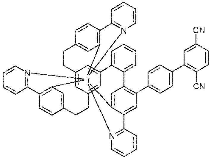
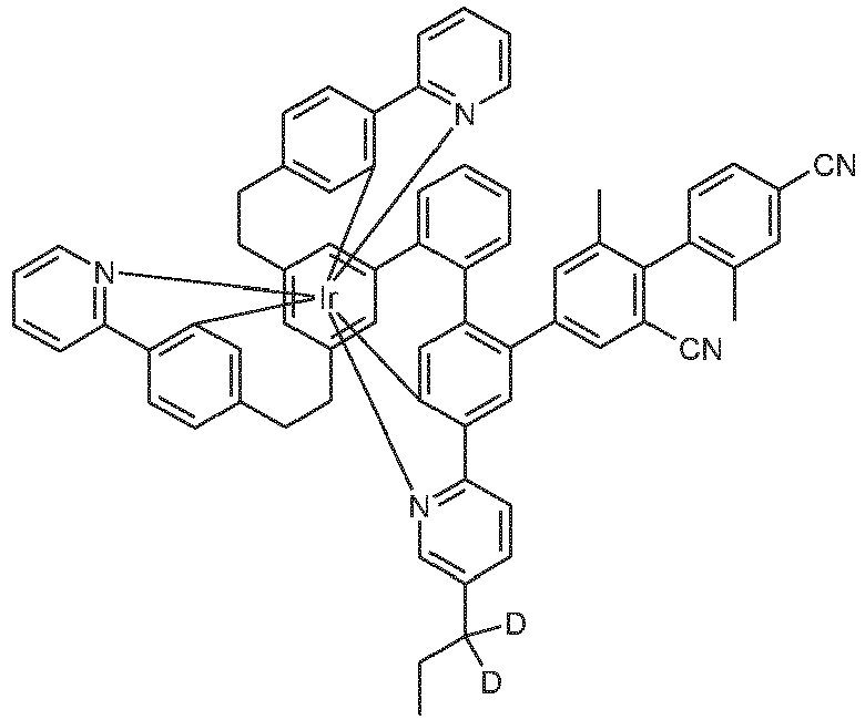
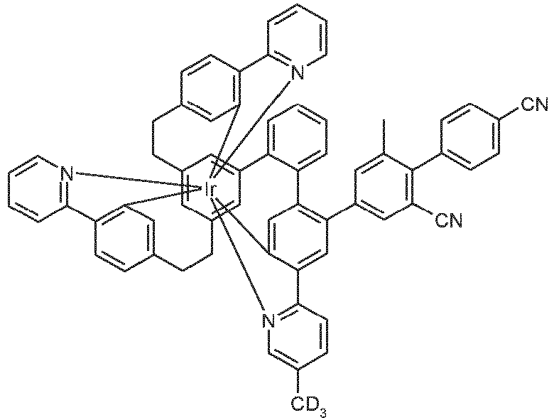
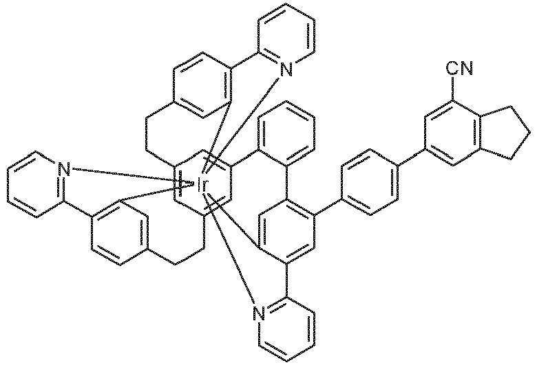
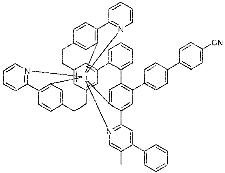
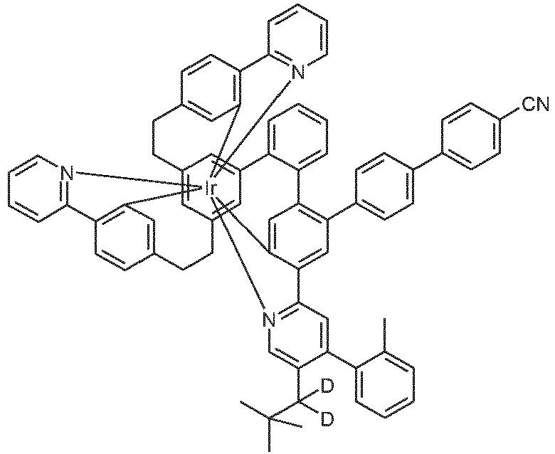
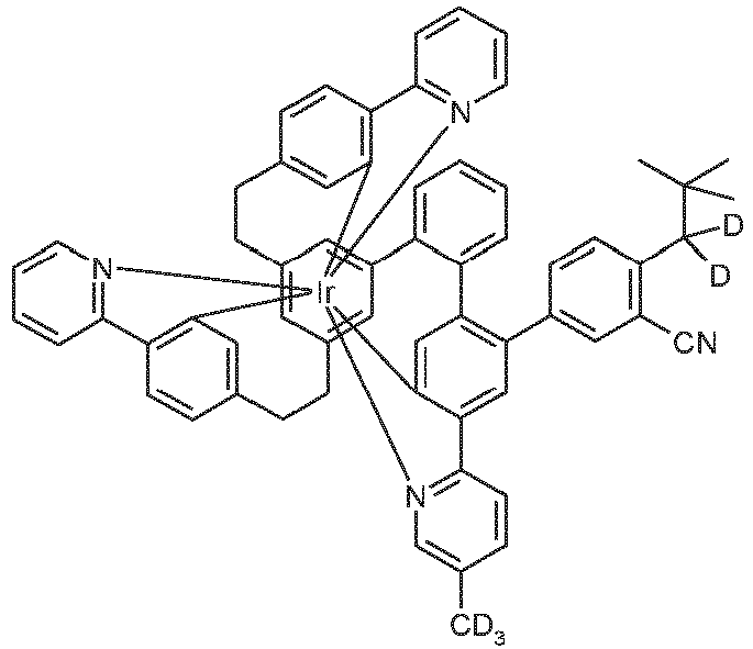
- Examples of suitable structures according to the invention are the compounds shown below. 1 2 3 4 5 6 7 8 9 10 11 12 13 14 15 16 17 18 19 20 21 22 23 24 25 26 27 28 29 30 31 32 33 34 35 36 37 38 39 40 41 42 43 44 45 46 47 48 49 50 51 52 53 54 55 56 57 58 59 60 61 62 63 64 65 66 67 68 69 70 71 72 73 74 75 76 77 78 79 80 81 82 83 84 85 86 87 88 89 90 91 92 93 94 95 96 97 98 99 100 101 102 103 104 105 106 107 108 109 110 111 112 113 114 115 116 117 118 119 120 121 122 123 124 125 126 127 128 129 130 131 132 133 134 135 136 138 139 140 141 142 143 144 145 146 147 149 150 151 152 153 154 155 156 157
- the metal complexes according to the invention are chiral structures. If the ligand L is also chiral, the formation of diastereomers and multiple enantiomer pairs is possible.
- the complexes according to the invention then include both mixtures of the various diastereomers or the corresponding racemates, as well as the individual isolated diastereomers or enantiomers.
- Racemate resolution via fractional crystallization of diastereomeric salt pairs can be performed using conventional methods. This involves oxidizing the neutral Ir(III) complexes (e.g., with peroxides, H 2 O 2 , or electrochemically), treating the resulting cationic Ir(IV) complexes with the salt of an enantiomerically pure, monoanionic base (chiral base), separating the resulting diasteromeric salts by fractional crystallization, and then reducing them to the enantiomerically pure neutral complex using a reducing agent (e.g., zinc, hydrazine hydrate, ascorbic acid, etc.), as schematically shown below:
- a reducing agent e.g., zinc, hydrazine hydrate, ascorbic acid, etc.
- an enantiomerically pure or enantiomerically enriched synthesis is possible by complexation in a chiral medium (e.g. R- or S-1,1-binaphthol).
- a chiral medium e.g. R- or S-1,1-binaphthol
- Enantiomerically pure C 1 -symmetric complexes can also be synthesized specifically, as shown in the following scheme. For this purpose, an enantiomerically pure, C 1 -symmetric ligand is prepared and complexed, the resulting diastereomeric mixture is separated, and the chiral group is subsequently cleaved.
- the compounds of the invention can, in principle, be prepared by various methods. Generally, an iridium salt is reacted with the corresponding free ligand.
- R preferably represents an alkyl group having 1 to 4 carbon atoms.
- Iridium compounds bearing alkoxide and/or halide and/or hydroxyl as well as ketoketonate residues can also be used. These compounds can also be charged. Corresponding iridium compounds that are particularly suitable as starting materials are described in WO 2004/085449 disclosed.
- [IrCl 2 (acac) 2 ] - for example Na[IrCl 2 (acac) 2 ], metal complexes with acetylacetonate derivatives as ligand, for example Ir(acac) 3 or tris(2,2,6,6-tetramethylheptane-3,5-dionato)iridium, and IrCl 3 ⁇ xH 2 O, where x usually stands for a number between 2 and 4.
- the synthesis of the complexes is preferably carried out as in WO 2002/060910 and in WO 2004/085449 Also particularly suitable is the synthesis in an organic acid or a mixture of an organic acid and an organic solvent, as described in the not yet published application EP19187468.4
- Particularly suitable reaction media are, for example, acetic acid or a mixture of salicylic acid and an organic solvent, for example, mesitylene.
- the synthesis can also be activated thermally, photochemically, and/or by microwave radiation. Furthermore, the synthesis can also be carried out in an autoclave at elevated pressure and/or elevated temperature.
- solvents or Melting aids can be added.
- Suitable solvents are protic or aprotic solvents, such as aliphatic and/or aromatic alcohols (methanol, ethanol, isopropanol, t-butanol, etc.), oligo- and polyalcohols (ethylene glycol, 1,2-propanediol, glycerol, etc.), alcohol ethers (ethoxyethanol, diethylene glycol, triethylene glycol, polyethylene glycol, etc.), ethers (di- and triethylene glycol dimethyl ether, diphenyl ether, etc.), aromatic, heteroaromatic and/or aliphatic hydrocarbons (toluene, xylene, mesitylene, chlorobenzene, pyridine, lutidine, quinoline, isoquinoline, tridecane, he
- Suitable melting aids are compounds that are solid at ambient temperature but melt upon heating the reaction mixture, dissolving the reactants to form a homogeneous melt.
- Particularly suitable are biphenyl, m-terphenyl, triphenylene, R- or S-binaphthol or the corresponding racemate, 1,2-, 1,3-, 1,4-bisphenoxybenzene, triphenylphosphine oxide, 18-crown-6, phenol, 1-naphthol, hydroquinone, etc.
- hydroquinone is particularly preferred.
- the compounds according to the invention according to formula (1) can be obtained in high purity, preferably more than 99% (determined by 1 H-NMR and/or HPLC).
- formulations of the iridium complexes according to the invention are required. These formulations can be, for example, solutions, dispersions, or emulsions. It may be preferred for this purpose To use mixtures of two or more solvents.
- Suitable and preferred solvents are, for example, toluene, anisole, o-, m- or p-xylene, methyl benzoate, mesitylene, tetralin, veratrole, THF, methyl-THF, THP, chlorobenzene, dioxane, phenoxytoluene, in particular 3-phenoxytoluene, (-)-fenchone, 1,2,3,5-tetramethylbenzene, 1,2,4,5-tetramethylbenzene, 1-methylnaphthalene, 2-methylbenzothiazole, 2-phenoxyethanol, 2-pyrrolidinone, 3-methylanisole, 4-methylanisole, 3,4-dimethylanisole, 3,5-dimethylanisole, acetophenone, ⁇ -terpineol, benzothiazole, butyl benzoate, cumene, cyclohexanol, cyclohexanone, cyclohexylbenzene, Decalin,
- the present invention therefore further provides a formulation comprising at least one compound according to the invention and at least one further compound.
- the further compound can be, for example, a solvent, in particular one of the above-mentioned solvents or a mixture of these solvents.
- the further compound can also be another organic or inorganic compound that is also used in the electronic device, for example, a matrix material.
- This further compound can also be polymeric.
- the compound according to the invention can be used in an electronic device as an active component, preferably as an emitter in the emissive layer of an organic electroluminescent device.
- the present invention thus further relates to the use of the compounds according to the invention in an electronic Device, in particular in an organic electroluminescent device.
- Yet another subject of the present invention is an electronic device comprising at least one compound according to the invention, in particular an organic electroluminescent device.
- An electronic device is understood to be a device that contains an anode, a cathode, and at least one layer, wherein this layer contains at least one organic or organometallic compound.
- the electronic device according to the invention thus contains an anode, a cathode, and at least one layer containing at least one iridium complex according to the invention.
- Preferred electronic devices are selected from the group consisting of organic electroluminescent devices (OLEDs, PLEDs), organic integrated circuits (O-ICs), organic field-effect transistors (O-FETs), organic thin-film transistors (O-TFTs), organic light-emitting transistors (O-LETs), organic solar cells (O-SCs), which include both purely organic solar cells and dye-sensitized solar cells, organic optical detectors, organic photoreceptors, organic field quench devices (O-FQDs), light-emitting electrochemical cells (LECs), oxygen sensors, or organic laser diodes (O-lasers), comprising at least one compound according to the invention in at least one layer.
- OLEDs organic electroluminescent devices
- O-ICs organic integrated circuits
- O-FETs organic field-effect transistors
- OF-TFTs organic thin-film transistors
- O-LETs organic light-emitting transistors
- O-SCs organic solar cells
- O-SCs organic solar cells
- Organic infrared electroluminescent devices are particularly preferred.
- Active components are generally the organic or inorganic materials introduced between the anode and cathode, for example, charge injection, charge transport, or charge blocking materials, but especially emission materials and matrix materials.
- the compounds according to the invention exhibit particularly good properties as emission materials in organic electroluminescent devices.
- a preferred embodiment of the invention is therefore organic electroluminescent devices.
- the compounds according to the invention can be used to generate singlet oxygen or in photocatalysis.
- the organic electroluminescent device contains a cathode, an anode, and at least one emitting layer. In addition to these layers, it may contain further layers, for example one or more hole injection layers, hole transport layers, hole blocking layers, electron transport layers, electron injection layers, exciton blocking layers, electron blocking layers, charge generation layers, and/or organic or inorganic p/n junctions.
- one or more hole transport layers can be p-doped, for example with metal oxides, such as MoO 3 or WO 3 , or with (per)fluorinated electron-deficient aromatics or with electron-deficient cyano-substituted heteroaromatics (e.g., according to JP 4747558 , JP 2006-135145 , US 2006/0289882 , WO 2012/095143 ), or with quinoid systems (e.g. according to EP1336208 ) or with Lewis acids, or with boranes (e.g.
- metal oxides such as MoO 3 or WO 3
- (per)fluorinated electron-deficient aromatics or with electron-deficient cyano-substituted heteroaromatics e.g., according to JP 4747558 , JP 2006-135145 , US 2006/0289882 , WO 2012/095143
- quinoid systems e.g. according to EP1336208
- Interlayers can also be introduced between two emitting layers, which, for example, have an exciton-blocking function and/or control the charge balance in the electroluminescent device and/or generate charges (charge generation layers, e.g., in layer systems with multiple emitting layers, e.g., in white-emitting OLED components). It should be noted, however, that not every one of these layers necessarily needs to be present.
- the organic electroluminescent device may contain one emitting layer or it may contain multiple emitting layers. If multiple emitting layers are present, these preferably have a total of multiple emission maxima between 380 nm and 750 nm, resulting in overall white emission, i.e., different emitting compounds that can fluoresce or phosphoresce are used in the emitting layers. In particular, Three-layer systems are preferred, with the three layers showing blue, green and orange or red emission (for the basic structure see e.g. WO 2005/011013 ) or systems that have more than three emitting layers. It can also be a hybrid system, where one or more layers are fluorescent and one or more other layers are phosphorescent. A preferred embodiment is tandem OLEDs. White-emitting organic electroluminescent devices can be used for lighting applications or, with a color filter, for full-color displays.
- the organic electroluminescent device contains the compound according to the invention as emitting compound in one or more emitting layers.
- the compound according to the invention When the compound according to the invention is used as an emitting compound in an emitting layer, it is preferably used in combination with one or more matrix materials.
- the mixture of the compound according to the invention and the matrix material contains between 0.1 and 99 vol. %, preferably between 1 and 90 vol. %, particularly preferably between 3 and 40 vol. %, in particular between 5 and 15 vol. % of the compound according to the invention, based on the total mixture of emitter and matrix material. Accordingly, the mixture contains between 99.9 and 1 vol. %, preferably between 99 and 10 vol. %, particularly preferably between 97 and 60 vol. %, in particular between 95 and 85 vol. % of the matrix material, based on the total mixture of emitter and matrix material.
- the matrix material any materials known in the art can be used as the matrix material.
- the triplet level of the matrix material is higher than the triplet level of the emitter.
- Suitable matrix materials for the compounds according to the invention are ketones, phosphine oxides, sulfoxides and sulfones, e.g. according to WO 2004/013080 , WO 2004/093207 , WO 2006/005627 or WHERE 2010/006680 , triarylamines, carbazole derivatives, e.g. B.
- CBP N,N-bis-carbazolylbiphenyl
- m-CBP or the in WO 2005/039246 , US 2005/0069729 , JP 2004/288381 , EP 1205527 , WO 2008/086851 or US 2009/0134784 disclosed carbazole derivatives, biscarbazole derivatives, indolocarbazole derivatives, e.g., according to WO 2007/063754 or WO 2008/056746 , Indenocarbazole derivatives, e.g. according to WO 2010/136109 or WO 2011/000455 , Azacarbazoles, e.g.
- WO 2010/015306 WO 2007/063754 or WO 2008/056746
- zinc complexes e.g. according to EP652273 or WO 2009/062578
- Dibenzofuran derivatives e.g. according to WO 2009/148015 or WO 2015/169412
- bridged carbazole derivatives e.g., according to US 2009/0136779 , WO 2010/050778 , WO 2011/042107 or WO 2011/088877 .
- polymers are also suitable as matrix materials, e.g., according to WO 2012/008550 or WO 2012/048778 , Oligomers or dendrimers, e.g., according to Journal of Luminescence 183 (2017), 150-158 .
- a preferred combination is, for example, the use of an aromatic ketone, a triazine derivative, a pyrimidine derivative, a phosphine oxide derivative, or an aromatic lactam with a triarylamine derivative or a carbazole derivative as a mixed matrix for the compound according to the invention.
- a mixture of a charge-transporting matrix material and an electrically inert matrix material which is not involved, or not involved to a significant extent, in charge transport, such as, for example, in WO 2010/108579 or WO 2016/184540
- two electron-transporting matrix materials for example triazine derivatives and lactam derivatives, as described, for example, in WO 2014/094964 described. Examples of compounds suitable as matrix materials for the compounds according to the invention are shown below.
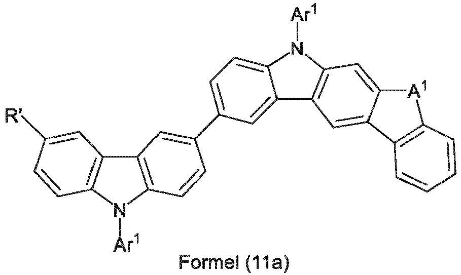
- Preferred embodiments of the compounds of formulas (10) and (11) are the compounds of the following formulas (10a) and (11a), where the symbols used have the meanings given above.
- Preferred dibenzofuran derivatives are the compounds of the following formula (12), where the oxygen can also be replaced by sulfur to form a dibenzothiophene, L 1 represents a single bond or an aromatic or heteroaromatic ring system having 5 to 30 aromatic ring atoms, preferably having 6 to 24 aromatic ring atoms, which can also be substituted by one or more radicals R', but is preferably unsubstituted, and R' and Ar 1 have the meanings given above.
- the two groups Ar 1 that bond to the same nitrogen atom, or a group Ar 1 and a group L that bond to the same nitrogen atom, can also be linked to one another, for example to form a carbazole.
- Preferred carbazolamines are the structures of the following formulas (13), (14) and (15), where L 1 , R' and Ar 1 have the meanings given above.
- suitable hole-conducting matrix materials are the compounds shown in the following table.
- Preferred triazine or pyrimidine derivatives which can be used as a mixture together with the compounds according to the invention are the compounds of the following formulas (16) and (17), where Ar 1 has the meanings given above.
- Ar 1 in formulas (16) and (17) is, on each occurrence, identically or differently, an aromatic or heteroaromatic ring system having 6 to 30 aromatic ring atoms, in particular having 6 to 24 aromatic ring atoms, which may be substituted by one or more radicals R'.
- Examples of suitable electron-transporting compounds which can be used as matrix materials together with the compounds according to the invention are the compounds shown in the following table.
- Metals with a low work function, metal alloys or multilayer structures made of different metals are preferred as the cathode, such as alkaline earth metals, alkali metals, main group metals or lanthanides (e.g. Ca, Ba, Mg, Al, In, Mg, Yb, Sm, etc.). Alloys made of an alkali or alkaline earth metal and silver are also suitable, for example an alloy of magnesium and silver.
- other metals can be used that have a relatively high work function, such as Ag, in which case combinations of the metals, such as Mg/Ag, Ca/Ag or Ba/Ag are generally used.
- a thin intermediate layer of a material with a high dielectric constant may also be preferred to have a thin intermediate layer of a material with a high dielectric constant.
- suitable materials for this purpose include alkali metal or alkaline earth metal fluorides, as well as the corresponding oxides or carbonates (e.g., LiF, Li 2 O, BaF 2 , MgO, NaF, CsF, Cs 2 CO 3 , etc.).
- Organic alkali metal complexes, such as Liq (lithium quinolinate), are also suitable.
- the thickness of this layer is preferably between 0.5 and 5 nm.
- the anode preferably has a work function greater than 4.5 eV vs. vacuum.
- Metals with a high redox potential such as Ag, Pt, or Au, are suitable for this purpose.
- Metal/metal oxide electrodes e.g., Al/Ni/NiO x , Al/PtO x
- at least one of the electrodes must be transparent or partially transparent to enable either the irradiation of the organic material (O-SC) or the coupling out of light (OLED/PLED, O-LASER).
- Preferred anode materials here are conductive mixed metal oxides.
- ITO Indium tin oxide
- IZO indium zinc oxide
- conductive, doped organic materials in particular conductive doped polymers, e.g., PEDOT, PANI, or derivatives of these polymers.
- a p-doped hole-transport material is applied to the anode as a hole-injection layer.
- Suitable p-dopants are metal oxides, for example MoO 3 or WO 3 , or (per)fluorinated electron-deficient aromatics.
- Other suitable p-dopants are HAT-CN (hexacyanohexaazatriphenylene) or the compound NPD9 from Novaled. Such a layer simplifies hole injection into materials with a deep HOMO, i.e., a large HOMO.
- Suitable charge transport materials such as those used in the hole injection or hole transport layer or electron blocking layer or in the Electron transport layer of the organic electroluminescent device according to the invention are, for example, those described in Y. Shirota et al., Chem. Rev. 2007, 107(4), 953-1010 disclosed compounds or other materials as used in these layers according to the prior art.
- Preferred hole transport materials that can be used in a hole transport, hole injection or electron blocking layer in the electroluminescent device according to the invention are indenofluorenamine derivatives (e.g. according to WO 06/122630 or WO 06/100896 ), which in EP 1661888 disclosed amine derivatives, hexaazatriphenylene derivatives (e.g.
- amine derivatives with condensed aromatics e.g. according to US 5,061,569 ), which in WO 95/09147 disclosed amine derivatives, monobenzoindenofluorenamines (e.g. according to WO 08/006449 ), dibenzoindenofluorenamines (e.g. according to WO 07/140847 ), spirobifluorene amines (e.g. according to WO 2012/034627 , WO2014/056565 ), fluorene amines (e.g. according to EP2875092 , EP2875699 and EP2875004 ), spiro-dibenzopyran amines (e.g. EP2780325 ) and dihydroacridine derivatives (e.g. according to WO 2012/150001 ).
- monobenzoindenofluorenamines e.g. according to WO 08/006449
- dibenzoindenofluorenamines e
- the device is structured accordingly (depending on the application), contacted and finally hermetically sealed, since the lifetime of such devices is drastically reduced in the presence of water and/or air.
- an organic electroluminescent device characterized in that one or more layers are coated using a sublimation process.
- the materials are vapor-deposited in vacuum sublimation systems at an initial pressure of typically less than 10 -5 mbar, preferably less than 10 -6 mbar. It is also possible for the initial pressure to be even lower or higher, for example, less than 10 -7 mbar.
- an organic electroluminescent device characterized in that one or more layers are coated using the OVPD (Organic Vapour Phase Deposition) method or by means of carrier gas sublimation.
- the materials at a pressure between 10 -5 mbar and 1 bar.
- OVJP Organic Vapour Jet Printing
- the materials are applied directly through a nozzle and thus structured (e.g. MS Arnold et al., Appl. Phys. Lett. 2008, 92, 053301 ).
- an organic electroluminescent device characterized in that one or more layers are produced from solution, such as by spin coating, or by any printing process, such as screen printing, flexographic printing, offset printing, or nozzle printing, but particularly preferably LITI (Light Induced Thermal Imaging, thermal transfer printing) or inkjet printing. Soluble compounds are required for this, which are obtained, for example, by suitable substitution.
- the organic electroluminescent device can also be manufactured as a hybrid system by applying one or more layers from solution and vapor-depositing one or more other layers. For example, it is possible to apply an emitting layer containing a metal complex according to the invention and a matrix material from solution and then vacuum-deposit a hole-blocking layer and/or an electron-transport layer thereon.
- the electronic devices according to the invention are distinguished from the prior art by their significantly improved lifetime compared to comparable structures that do not have a cyano group on the phenyl or biphenyl substituent. At the same time, a slight improvement in efficiency and voltage is achieved.
- the following syntheses are carried out under a protective gas atmosphere in dried solvents.
- the metal complexes are also handled in the absence of light or under yellow light.
- the solvents and reagents can be obtained, for example, from Sigma-ALDRICH or ABCR.
- the respective information in square brackets or the numbers given for individual compounds refer to the CAS numbers of the compounds known from the literature. For compounds that can exhibit multiple tautomeric, isomeric, diastereomeric, and enantiomeric forms, one form is shown as a representative example.
- a mixture of 7.71 g (10 mmol) of ligand L1, 4.90 g (10 mmol) of tris-acetylacetonato-iridium(III) [15635-87-7], and 120 g of hydroquinone [123-31-9] is placed in a 1000 mL two-neck round-bottom flask with a glass-jacketed magnetic core.
- the flask is equipped with a water separator (for media less dense than water) and an air cooler with an argon blanket.
- the flask is placed in a metal heating dish.
- the apparatus is purged with argon from above via the argon blanket for 15 min, while the argon is allowed to escape from the side neck of the two-neck flask.
- a glass-jacketed Pt-100 thermocouple is inserted into the flask via the side neck of the two-neck flask and placed just above the magnetic stirrer bar.
- the apparatus is then thermally insulated with several loose wraps of household aluminum foil, with the insulation extending to the middle of the riser tube of the water separator.
- the apparatus is then rapidly heated to 240–245 °C using a laboratory stirrer, as measured by a Pt-100 thermocouple immersed in the molten, stirred reaction mixture.
- the reaction mixture is held at 240–245 °C for the next 1 h, during which a small amount of condensate distills off and collects in the water separator.
- the core fraction is removed and concentrated in a rotary evaporator, while MeOH is continuously added dropwise until crystallization occurs. After filtration, washing with a small amount of MeOH, and drying in vacuo, the yellow product is further purified by four continuous hot extractions with dichloromethane/i-propanol 1:1 (vv) and then four hot extractions with dichloromethane/acetonitrile (initial quantity approx. 200 ml each, extraction thimble: standard Soxhlett thimbles made of cellulose from Whatman) under careful exclusion of air and light.
- the loss to the mother liquor can be adjusted by the ratio of dichloromethane (low boilers and good solvent) : i-propanol or acetonitrile (high boilers and poor solvent). Typically, it should be 3-6 wt.% of the initial amount. Other solvents such as toluene, xylene, ethyl acetate, butyl acetate, etc. can also be used for hot extraction. Finally, the product is fractionally sublimed under high vacuum at p ⁇ 10 -6 mbar and T ⁇ 330 - 430 °C. Yield: 4.91 g (5.1 mmol), 51%; Purity: > 99.9% according to HPLC.
- the metal complexes are typically obtained as a 1:1 mixture of the A and ⁇ isomers/enantiomers.
- the complex images shown below typically show only one isomer. If ligands with three different partial ligands are used, or if chiral ligands are used as a racemate, the derived metal complexes are obtained as a mixture of diastereomers. These can be separated by fractional crystallization or chromatography, e.g., using an automated column chromatography system (CombiFlash from A. Semrau).
- the derived metal complexes are obtained as a mixture of diastereomers, the separation of which by fractional crystallization or chromatography leads to pure enantiomers.
- the separated diastereomers or enantiomers can be further purified as described above, e.g., by hot extraction.
- the clear yellow-orange solution is stirred at 80 °C for a further 30 min for complexes with methyl/methylene groups para to the pyridine nitrogen or for a further 6 h for complexes with methyl/methylene groups meta to the pyridine nitrogen, then cooled using a cold water bath, treated dropwise from ⁇ 60 °C with 20 ml of 1N DCI in D 2 O, allowed to cool to room temperature, stirred for a further 5 h, suction filtered from the solid and Wash the mixture three times with 10 ml of H 2 O/MeOH (1:1, vv) and then three times with 10 ml of MeOH, and dry in vacuo.
- deuterated complexes can be prepared analogously: e.g. reactant product yield Ir(L103-D9) Ir(L103) 78% Ir(L104-D9) Ir(L104) 85%
- OLEDs according to the invention as well as OLEDs according to the prior art is carried out according to a general process according to WO 2004/058911 which is adapted to the conditions described here (layer thickness variation, materials used).
- Cleaned glass plates (cleaned in a Miele laboratory dishwasher, using Merck Extran cleaner) coated with 50 nm thick structured ITO (indium tin oxide) are annealed for 15 minutes at 250 °C under nitrogen.
- the pre-cleaned ITO substrates are subjected to a two-gas plasma process (oxygen followed by argon) for final cleaning of the ITO surface and adjustment of the ITO work function.
- These coated glass plates form the substrates onto which the OLEDs are applied. All materials are applied by thermal vacuum deposition.
- the emission layer always consists of at least one matrix material (host material) and an emissive dopant (emitter), which is added to the matrix material(s) in a specific volume fraction by co-evaporation.
- M1:M2:Ir-Emitter 29.5%:58.5:12%
- M1:M2:Ir-Emitter 29.5%:58.5:12%
- the electron-transport layer also consists of a mixture of two materials.
- the OLEDs essentially have the following layer structure: ITO substrate / Hole injection layer 1 (HIL1) consisting of HTM1 doped with 5% NDP-9 (commercially available from Novaled), 20 nm / Hole transport layer 1 (HTL1) consisting of HTM1, 40 nm / Hole transport layer 2 (HTL2), 20 nm / Emission layer (EML), see Table 1 / Hole blocking layer (HBL), see Table 1 / Electron transport layer (ETL), see Table 1 / Electron injection layer (EIL), see Table 1 / 100 nm thick aluminum layer as cathode.
- HIL1 Hole injection layer 1
- HTL1 Hole transport layer 1
- EML2 Emission layer
- HBL Hole blocking layer
- ETL Electron transport layer
- EIL Electron injection layer
- the OLEDs are characterized as standard.
- the electroluminescence spectra are determined at a luminance of 1000 cd/ m2 , and the CIE 1931 x and y color coordinates are calculated from this.
- the lifetime LD90 is defined as the time after which the luminance has decreased to 90% of the starting luminance when operated at an initial brightness of 10000 cd/ m2 .
- the OLEDs can also be initially operated at other starting luminances. The lifetime values can then be converted to values for other starting luminances using conversion formulas familiar to those skilled in the art.
- the compounds of the invention can be used, among other things, as phosphorescent emitter materials in the emission layer of OLEDs.
- the iridium compounds shown in Table 3 were used as a comparison according to the state of the art.
- the OLED results are summarized in Table 2.
- the compounds according to the invention when used as emitters in an OLED, lead to a slight improvement in efficiency and voltage with a simultaneous significant improvement in lifetime, for example a 60% improvement in lifetime in the case of the complex Ir(L100) according to the invention compared to the complex Ir-Ref.1 according to the prior art, which has the same structure as Ir(L100) but does not contain a cyano group on the biphenyl substituent.
- Table 1 Structure of the OLEDs ⁇ /b> e.g.
Landscapes
- Chemical & Material Sciences (AREA)
- Organic Chemistry (AREA)
- Engineering & Computer Science (AREA)
- Materials Engineering (AREA)
- Physics & Mathematics (AREA)
- Optics & Photonics (AREA)
- Crystallography & Structural Chemistry (AREA)
- Inorganic Chemistry (AREA)
- Electroluminescent Light Sources (AREA)
- Organic Low-Molecular-Weight Compounds And Preparation Thereof (AREA)
Description
- Die vorliegende Erfindung betrifft Iridiumkomplexe, welche sich für den Einsatz in organischen Elektrolumineszenzvorrichtungen, insbesondere als Emitter, eignen.
- Gemäß dem Stand der Technik werden in phosphoreszierenden organischen Elektrolumineszenzvorrichtungen (OLEDs) als Triplettemitter vor allem bis- und tris-ortho-metallierte Irdiumkomplexe mit aromatischen Liganden eingesetzt, wobei die Liganden über ein negativ geladenes Kohlenstoffatom und ein neutrales Stickstoffatom. Beispiele für solche Komplexe sind Tris(phenylpyridyl)iridium(III) und Derivate davon. Derartige Komplexe sind auch mit polypodalen Liganden bekannt, wie beispielsweise in
US 7,332,232 ,WO 2016/124304 undWO 2019/158453 beschrieben. Auch wenn diese Komplexe mit polypodalen Liganden Vorteile gegenüber den Komplexen zeigen, die ansonsten die gleiche Ligandenstruktur aufweisen, deren einzelne Liganden nicht polypodal verbrückt sind, gibt es auch noch Verbesserungsbedarf, beispielsweise im Hinblick auf Effizienz, Spannung und Lebensdauer. - Aufgabe der vorliegenden Erfindung ist daher die Bereitstellung verbesserter Iridiumkomplexe, welche sich als Emitter für die Verwendung in OLEDs eignen.
- Überraschend wurde gefunden, dass Iridiumkomplexe mit einem hexadentaten tripodalen Liganden, der die nachfolgend beschriebene Struktur aufweist, diese Aufgabe lösen und sich sehr gut für die Verwendung in einer organischen Elektrolumineszenzvorrichtung eignen. Diese Iridiumkomplexe und organische Elektrolumineszenzvorrichtungen, welche diese Komplexe enthalten, sind daher der Gegenstand der vorliegenden Erfindung.
- Gegenstand der Erfindung ist somit eine Verbindung der Formel (1),
Ir(L) Formel (1) - wobei der Ligand L eine Struktur der folgenden Formel (2) aufweist:
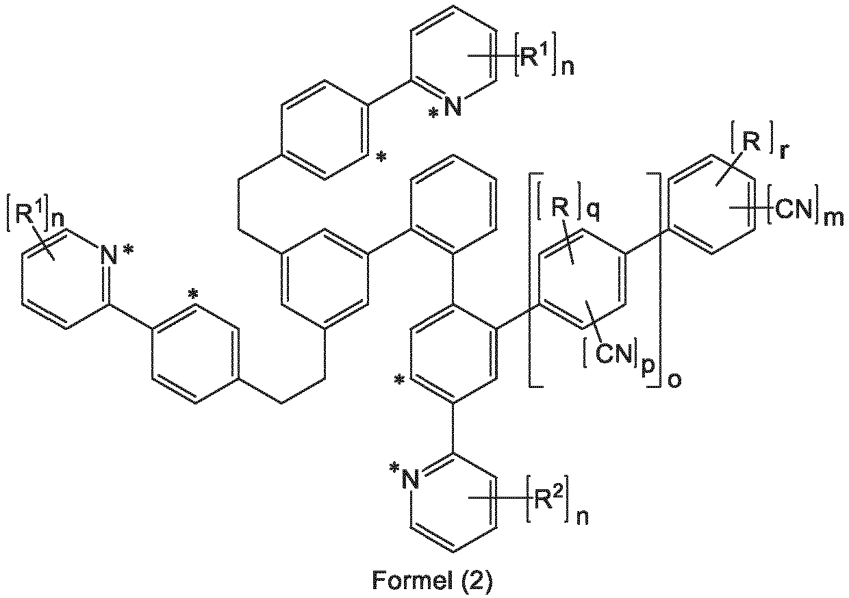
- wobei der Ligand L über die mit * gekennzeichneten Positionen an das Iridiumatom koordiniert und wobei die nicht explizit eingezeichneten H-Atome auch durch D ersetzt sein können und wobei für die verwendeten Symbole und Indizes gilt:
- R
- ist gleich oder verschieden bei jedem Auftreten H, D, F, eine lineare Alkylgruppe mit 1 bis 10 C-Atomen oder eine verzweigte oder cyclische Alkylgruppe mit 3 bis 10 C-Atomen, wobei die Alkylgruppe jeweils auch deuteriert sein kann; dabei können zwei benachbarte Reste R miteinander ein Ringsystem bilden;
- R1
- ist gleich oder verschieden bei jedem Auftreten H, D, eine lineare Alkylgruppe mit 1 bis 10 C-Atomen oder eine verzweigte oder cyclische Alkylgruppe mit 3 bis 10 C-Atomen, wobei die Alkylgruppe jeweils auch deuteriert sein kann; dabei können zwei benachbarte Reste R1 miteinander ein Ringsystem bilden;
- R2
- ist gleich oder verschieden bei jedem Auftreten H, D, eine lineare Alkylgruppe mit 1 bis 10 C-Atomen, eine verzweigte oder cyclische Alkylgruppe mit 3 bis 10 C-Atomen, wobei die Alkylgruppe jeweils auch deuteriert sein kann, oder eine Phenyl- oder Biphenylgruppe, die jeweils durch ein oder mehrere Alkylgruppen mit 1 bis 10 C-Atomen substituiert sein kann, wobei die Phenyl- bzw. Biphenylgruppe bzw. die Alkylgruppen jeweils auch deuteriert sein können; dabei können zwei benachbarte Reste R2 miteinander ein Ringsystem bilden;
- m
- ist 1, 2 oder 3;
- n
- ist bei jedem Auftreten gleich oder verschieden 0, 1, 2 oder 3;
- o
- ist 0 oder 1;
- p
- ist 0, 1 oder 2;
- q
- ist 0, 1 oder 2;
- r
- ist 0, 1 oder 2.
- Bei dem Liganden L der Formel (2) handelt es sich somit um einen hexadentaten, tripodalen Liganden mit den drei bidentaten Phenylpyridin-Teilliganden. Der mit diesem Liganden gebildete Komplex Ir(L) der Formel (1) weist somit die folgende Struktur auf:

- Wenn zwei Reste R bzw. zwei Reste R1 bzw. zwei Reste R2 miteinander ein Ringsystem bilden, so kann dieses mono- oder polycyclisch sein. Dabei sind die Reste, die miteinander ein Ringsystem bilden, benachbart, d. h. dass diese Reste an Kohlenstoffatome binden, die direkt aneinander gebunden sind. Unter der Formulierung, dass zwei Reste R miteinander einen Ring bilden können, soll im Rahmen der vorliegenden Beschreibung unter anderem verstanden werden, dass die beiden Reste miteinander durch eine chemische Bindung unter formaler Abspaltung von zwei Wasserstoffatomen verknüpft sind. Dies wird durch das folgende Schema verdeutlicht:

- Unter einer cyclischen Alkylgruppe im Sinne dieser Erfindung wird eine monocyclische, eine bicyclische oder eine polycyclische Gruppe verstanden.
- Im Rahmen der vorliegenden Erfindung werden unter einer C1- bis C10-Alkylgruppe beispielsweise die Reste Methyl, Ethyl, n-Propyl, i-Propyl, Cyclopropyl, n-Butyl, i-Butyl, s-Butyl, t-Butyl, Cyclobutyl, 2-Methylbutyl, n-Pentyl, s-Pentyl, t-Pentyl, 2-Pentyl, neo-Pentyl, Cyclopentyl, n-Hexyl, s-Hexyl, t-Hexyl, 2-Hexyl, 3-Hexyl, neo-Hexyl, Cyclohexyl, 1-Methylcyclopentyl, 2-Methylpentyl, n-Heptyl, 2-Heptyl, 3-Heptyl, 4-Heptyl, Cycloheptyl, 1-Methylcyclohexyl, n-Octyl, 2-Ethylhexyl, Cyclooctyl, 1-Bicyclo[2,2,2]octyl, 2-Bicyclo[2,2,2]octyl, 2-(2,6-Dimethyl)octyl, 3-(3,7-Dimethyl)octyl, Adamantyl, 1,1-Dimethyl-n-hex-1-yl-, 1,1-Dimethyl-n-hept-1-yl-, 1,1-Dimethyl-n-oct-1-yl-, 1,1-Diethyl-n-hex-1-yl-, 1-(n-Propyl)-cyclohex-1-yl- und 1-(n-Butyl)-cyclohex-1-yl- verstanden.
- Wenn die Indizes n, p, q bzw. r = 0 sind, ist anstelle der entsprechenden Substiutenenten jeweils ein Wasserstoff- bzw. Deuteriumatom an die entsprechende Phenyl- bzw. Pyridingruppe gebunden.
- Für m = 1 steht der Ligand L bevorzugt für eine Struktur der folgenden Formel (3a), für m = 2 steht der Ligand L bevorzugt für eine Struktur der folgenden Formel (3b) oder (3c) und für m = 3 steht der Ligand L bevorzugt für eine Struktur der folgenden Formel (3d) oder (3e),


- Bevorzugt ist die Struktur der Formel (3a).
- Wenn o = 1 ist, sind bevorzugte Ausführungsformen q = 0 und p = 0, 1 oder 2 oder q = 0, 1 oder 2 und p = 0. Für o = 1 und p = 1 weist der Ligand bevorzugt eine Struktur der folgenden Formel (4a) auf, und für o = 1 und p = 2 weist der Ligand bevorzugt eine Struktur der folgenden Formel (4b) auf,


- In einer bevorzugten Ausführungsform der Erfindung sind die Indizes n an den beiden Phenylpyridin-Teilliganden, die nicht mit der Cyanophenyl- bzw. Cyanobiphenylgruppe substituiert sind, = 0. In einer weiteren bevorzugten Ausführungsform der Erfindung sind diese Indizes n = 1 oder 2 und die entsprechenden Reste R1 sind ungleich H oder D. Wenn diese Indizes n = 1 sind, weist der Ligand bevorzugt eine Struktur der folgenden Formel (5a) oder (5b) auf, und wenn diese Indizes n = 2 sind, weist der Ligand bevorzugt eine Struktur der folgenden Formel (5c) auf,


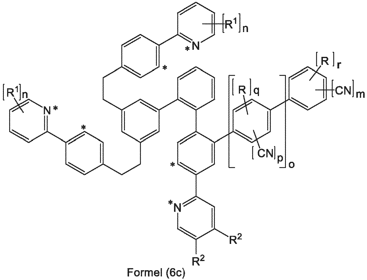
- In einer weiteren bevorzugten Ausführungsform der Erfindung ist der Index n an dem Phenylpyridin-Teilliganden, die mit der Cyanophenyl- bzw. Cyanobiphenylgruppe substituiert sind, = 0. In einer weiteren bevorzugten Ausführungsform der Erfindung ist dieser Index n = 1 oder 2 und die entsprechenden Reste R2 sind ungleich H oder D. Wenn dieser Index n = 1 ist, weist der Ligand bevorzugt eine Struktur der folgenden Formel (6a) oder (6b) auf, und wenn dieser Index n = 2 ist, weist der Ligand bevorzugt eine Struktur der folgenden Formel (6c) auf,


- Bevorzugt weist der Ligand L eine Struktur der folgenden Formel (7) auf,

- In einer bevorzugten Ausführungsform der Erfindung sind die Substituenten R gleich oder verschieden bei jedem Auftreten ausgewählt aus der Gruppe bestehend aus D, einer linearen Alkylgruppe mit 1 bis 6 C-Atomen oder einer verzweigten oder cyclischen Alkylgruppe mit 3 bis 6 C-Atomen, wobei die Alkylgruppen jeweils auch deuteriert sein können. Besonders bevorzugt sind die Substituenten R gleich oder verschieden bei jedem Auftreten ausgewählt aus der Gruppe bestehend aus D, einer linearen Alkylgruppe mit 1 bis 4 C-Atomen oder einer verzweigten Alkylgruppe mit 3 oder 4 C-Atomen, wobei die Alkylgruppen jeweils auch deuteriert sein können. Insbesondere bevorzugt ist R eine Methylgruppe oder eine CD3-Gruppe.
- In einer weiteren bevorzugten Ausführungsform der Erfindung sind die Substituenten R1 gleich oder verschieden bei jedem Auftreten ausgewählt aus der Gruppe bestehend aus D, einer linearen Alkylgruppe mit 1 bis 6 C-Atomen oder einer verzweigten oder cyclischen Alkylgruppe mit 3 bis 6 C-Atomen, wobei die Alkylgruppen jeweils auch deuteriert sein können; dabei können zwei benachbarte Reste R1 miteinander ein Ringsystem bilden. Besonders bevorzugt sind die Substituenten R1 gleich oder verschieden bei jedem Auftreten ausgewählt aus der Gruppe bestehend aus D, einer linearen Alkylgruppe mit 1 bis 4 C-Atomen oder einer verzweigten Alkylgruppe mit 3 oder 4 C-Atomen, wobei die Alkylgruppen jeweils auch deuteriert sein können; dabei können zwei benachbarte Reste R1 miteinander ein Ringsystem bilden. Insbesondere bevorzugt ist R1 eine Methylgruppe oder eine CD3-Gruppe.
- In einer weiteren bevorzugten Ausführungsform der Erfindung sind die Substituenten R2 gleich oder verschieden bei jedem Auftreten ausgewählt aus der Gruppe bestehend aus D, einer linearen Alkylgruppe mit 1 bis 6 C-Atomen oder einer verzweigten oder cyclischen Alkylgruppe mit 3 bis 6 C-Atomen, wobei die Alkylgruppen jeweils auch deuteriert sein können, oder eine optional deuterierte Phenylgruppe, die durch ein oder mehrere optional deuterierte Alkylgruppen mit 1 bis 4 C-Atomen substituiert sein kann; dabei können zwei benachbarte Reste R2 miteinander ein Ringsystem bilden. Besonders bevorzugt sind die Substituenten R2 gleich oder verschieden bei jedem Auftreten ausgewählt aus der Gruppe bestehend aus D, einer linearen Alkylgruppe mit 1 bis 4 C-Atomen oder einer verzweigten Alkylgruppe mit 3 oder 4 C-Atomen, wobei die Alkylgruppen jeweils auch deuteriert sein können; dabei können zwei benachbarte Reste R2, wenn diese für Alkylgruppen stehen, miteinander ein Ringsystem bilden. Insbesondere bevorzugt ist R2 eine Methylgruppe oder eine CD3-Gruppe. Wenn R2 für eine optional deuterierte Phenylgruppe steht, ist diese bevorzugt unsubstituiert oder mit ein oder zwei optional deuterierten Alkylgruppen, bevorzugt Methylgruppen oder CD3-Gruppen substituiert, wobei diese Alkylgruppen dann bevorzugt in der ortho-Position zur Verknüpfung der Phenylgruppe gebunden sind.
- In einer weiteren bevorzugten Ausführungsform der Erfindung ist m = 1 oder 2, besonders bevorzugt 1.
- In einer weiteren bevorzugten Ausführungsform der Erfindung ist n bei jedem Auftreten gleich oder verschieden 0, 1 oder 2.
- In einer weiteren bevorzugten Ausführungsform der Erfindung ist o = 1. Wenn n am gleichen Liganden = 1 ist und R2 für eine Phenylgruppe steht, ist auch o = 1 bevorzugt.
- In einer weiteren bevorzugten Ausführungsform der Erfindung ist p = 0 oder 1, besonders bevorzugt = 0.
- In einer weiteren bevorzugten Ausführungsform der Erfindung ist q = 0 oder 1.
- In einer weiteren bevorzugten Ausführungsform der Erfindung ist r = 0 oder 1.
- Bevorzugt treten mehrere der oben genannten Bevorzugungen gleichzeitig auf. Bevorzugt gilt daher für die Symbole und Indizes:
- R
- ist gleich oder verschieden bei jedem Auftreten ausgewählt aus der Gruppe bestehend aus D, einer linearen Alkylgruppe mit 1 bis 6 C-Atomen oder einer verzweigten oder cyclischen Alkylgruppe mit 3 bis 6 C-Atomen, wobei die Alkylgruppen jeweils auch deuteriert sein können;
- R1
- ist gleich oder verschieden bei jedem Auftreten ausgewählt aus der Gruppe bestehend aus D, einer linearen Alkylgruppe mit 1 bis 6 C-Atomen oder einer verzweigten oder cyclischen Alkylgruppe mit 3 bis 6 C-Atomen, wobei die Alkylgruppen jeweils auch deuteriert sein können; dabei können zwei benachbarte Reste R1 miteinander ein Ringsystem bilden;
- R2
- ist gleich oder verschieden bei jedem Auftreten ausgewählt aus der Gruppe bestehend aus D, einer linearen Alkylgruppe mit 1 bis 6 C-Atomen oder einer verzweigten oder cyclischen Alkylgruppe mit 3 bis 6 C-Atomen, wobei die Alkylgruppen jeweils auch deuteriert sein können, oder eine optional deuterierte Phenylgruppe, die durch ein oder mehrere optional deuterierte Alkylgruppen mit 1 bis 4 C-Atomen substituiert sein kann; dabei können zwei benachbarte Reste R2 miteinander ein Ringsystem bilden;
- m
- ist 1 oder 2;
- n
- ist bei jedem Auftreten gleich oder verschieden 0, 1 oder 2;
- o
- ist 1; oder o ist 0 oder 1, wenn n am gleichen Liganden = 1 ist und R2 für eine Phenylgruppe steht;
- p
- ist 0 oder 1;
- q
- ist 0 oder 1;
- r
- ist 0 oder 1.
- Besonders bevorzugt gilt für die Symbole und Indizes:
- R
- ist gleich oder verschieden bei jedem Auftreten ausgewählt aus der Gruppe bestehend aus D, einer linearen Alkylgruppe mit 1 bis 4 C-Atomen oder einer verzweigten Alkylgruppe mit 3 oder 4 C-Atomen, wobei die Alkylgruppen jeweils auch deuteriert sein können;
- R1
- ist gleich oder verschieden bei jedem Auftreten ausgewählt aus der Gruppe bestehend aus D, einer linearen Alkylgruppe mit 1 bis 4 C-Atomen oder einer verzweigten Alkylgruppe mit 3 oder 4 C-Atomen, wobei die Alkylgruppen jeweils auch deuteriert sein können; dabei können zwei benachbarte Reste R1 miteinander ein Ringsystem bilden;
- R2
- ist gleich oder verschieden bei jedem Auftreten ausgewählt aus der Gruppe bestehend aus D, einer linearen Alkylgruppe mit 1 bis 4 C-Atomen oder einer verzweigten Alkylgruppe mit 3 oder 4 C-Atomen, wobei die Alkylgruppen jeweils auch deuteriert sein können, oder eine optional deuterierte Phenylgruppe, die durch ein oder mehrere optional deuterierte Alkylgruppen mit 1 bis 4 C-Atomen substituiert sein kann; dabei können zwei benachbarte Alkylgruppen R2 miteinander ein Ringsystem bilden;
- m
- ist 1;
- n
- ist bei jedem Auftreten gleich oder verschieden 0, 1 oder 2;
- o
- ist 1; oder o ist 0 oder 1, wenn n am gleichen Liganden = 1 ist und R2 für eine Phenylgruppe steht;
- p
- ist 0;
- q
- ist 0 oder 1;
- r
- ist 0 oder 1.
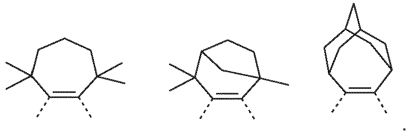
- Wenn zwei Reste R bzw. R1 bzw. R2 für Alkylgruppen stehen, die miteinander ein Ringsystem bilden, so ist dieses Ringsystem bevorzugt ausgewählt aus den Strukturen der folgenden Formeln (Ring-1) bis (Ring-7)


- R3
- ist gleich oder verschieden bei jedem Auftreten H, D oder eine Alkylgruppe mit 1, 2 oder 3 C-Atomen;
- G
- ist eine Alkylengruppe mit 1 oder 2 C-Atomen.
- In den oben abgebildeten Strukturen (Ring-1) bis (Ring-7) sowie den weiteren als bevorzugt genannten Ausführungsformen dieser Strukturen wird formal eine Doppelbindung zwischen den zwei Kohlenstoffatomen abgebildet. Dies stellt eine Vereinfachung der chemischen Struktur dar, da diese beiden Kohlenstoffatome in ein aromatisches oder heteroaromatisches System eingebunden sind und somit die Bindung zwischen diesen beiden Kohlenstoffatomen formal zwischen dem Bindungsgrad einer Einfachbindung und dem einer Doppelbindung liegt. Das Einzeichnen der formalen Doppelbindung ist somit nicht limitierend für die Struktur auszulegen, sondern es ist für den Fachmann offensichtlich, dass es sich hier um eine aromatische Bindung handelt.
- Wenn benachbarte Reste in den erfindungsgemäßen Strukturen ein aliphatisches Ringsystem bilden, dann ist es bevorzugt, wenn dieses keine aziden benzylischen Protonen aufweist. Unter benzylischen Protonen werden Protonen verstanden, die an ein Kohlenstoffatom binden, welches direkt an den Liganden gebunden sind. Dies kann dadurch erreicht werden, dass die Kohlenstoffatome des aliphatischen Ringsystems, die direkt an eine Aryl- oder Heteroarylgruppe binden, vollständig substituiert sind und keine Wasserstoffatome gebunden enthalten. So wird die Abwesenheit von aziden benzylischen Protonen in den Formeln (Ring-1) bis (Ring-3) dadurch erreicht, dass R3 in den benzylischen Positionen für eine Alkylgruppe steht. Dies kann weiterhin auch dadurch erreicht werden, dass die Kohlenstoffatome des aliphatischen Ringsystems, die direkt an eine Pyridin- oder Phenylgruppe binden, die Brückenköpfe einer bi- oder polycyclischen Struktur sind. Die an Brückenkopfkohlenstoffatome gebundenen Protonen sind aufgrund der räumlichen Struktur des Bi- oder Polycyclus wesentlich weniger azide als benzylische Protonen an Kohlenstoffatomen, die nicht in einer bi- oder polycyclischen Struktur gebunden sind, und werden im Sinne der vorliegenden Erfindung als nicht-azide Protonen angesehen.
- Beispiele für geeignete Gruppen der Struktur (Ring-1) sind die im Folgenden aufgeführten Strukturen:


- Beispiele für geeignete Gruppen der Formel (Ring-2) sind die im Folgenden aufgeführten Strukturen:

- Beispiele für geeignete Gruppen der Formeln (Ring-3), (Ring-6) und (Ring-7) sind die im Folgenden aufgeführten Strukturen:
- Beispiele für geeignete Gruppen der Formel (Ring-4) sind die im Folgenden aufgeführten Strukturen:


- Beispiele für geeignete Gruppen der Formel (Ring-5) sind die im Folgenden aufgeführten Strukturen:

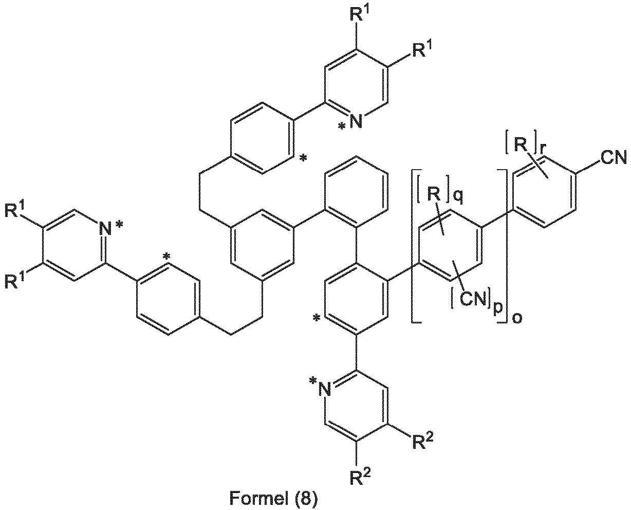
- In einer besonders bevorzugten Ausführungsform der Erfindung weist der Ligand L eine Struktur der folgenden Formel (8) auf,
- Ganz besonders bevorzugt weist der Ligand L eine Struktur der folgenden Formel (9) auf,

- Die oben genannten bevorzugten Ausführungsformen sind beliebig miteinander kombinierbar. In einer besonders bevorzugten Ausführungsform der Erfindung gelten die oben genannten bevorzugten Ausführungsformen gleichzeitig.
- Beispiele für geeignete erfindungsgemäße Strukturen sind die nachfolgend abgebildeten Verbindungen.


1 2 

3 4 
5 6 

7 8 

9 10 

11 12 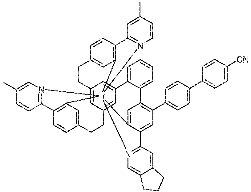

13 14 

15 16 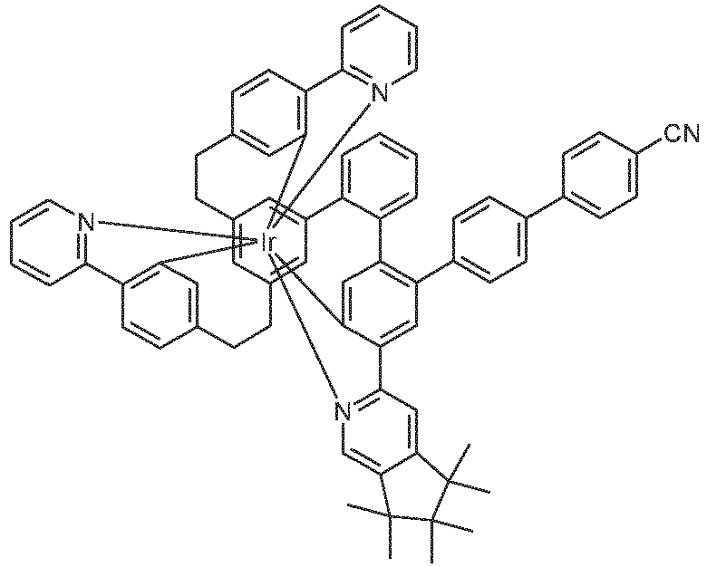

17 18 

19 20 

21 22 

23 24 

25 26 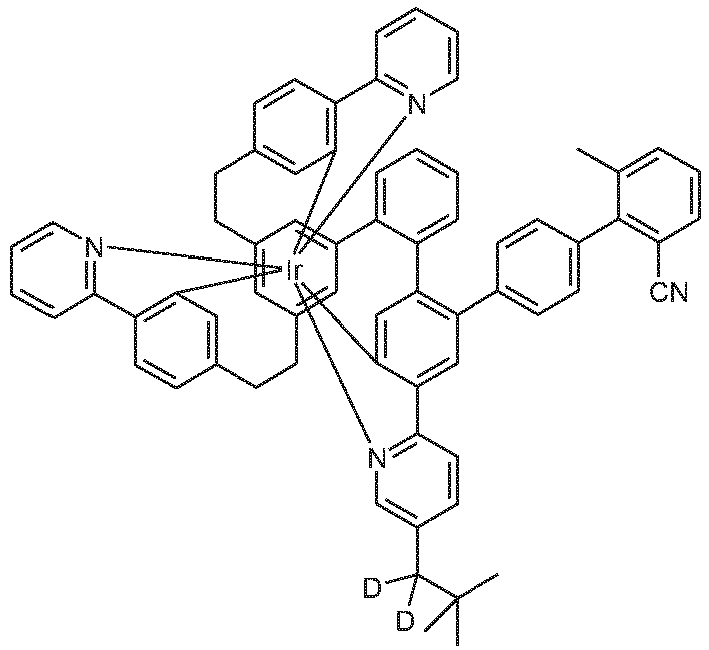

27 28 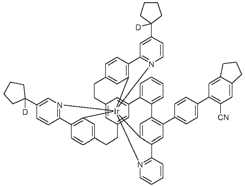

29 30 

31 32 

33 34 

35 36 

37 38 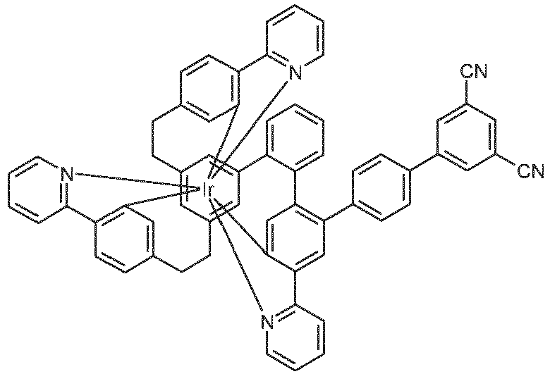

39 40 

41 42 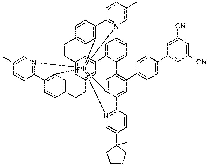

43 44 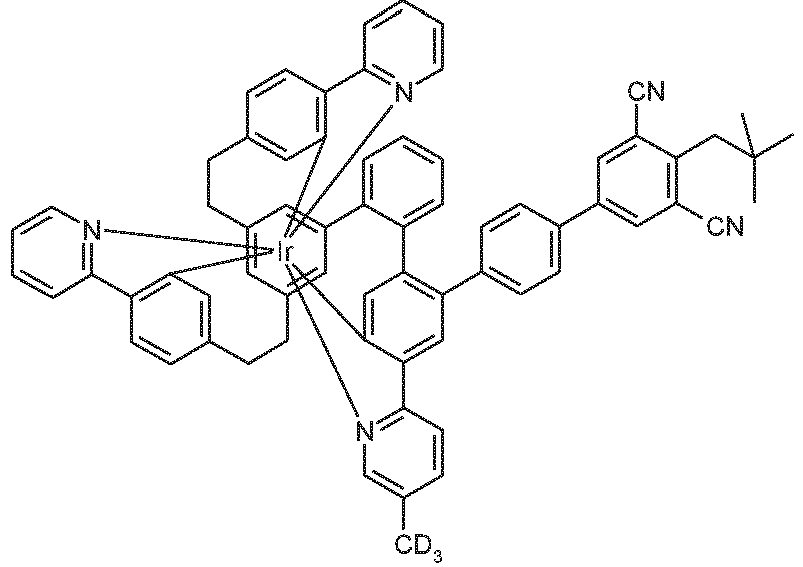

45 46 
47 48 

49 50 
51 52 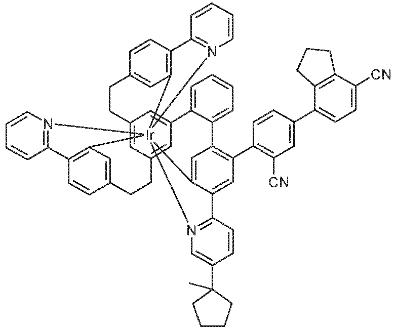

53 54 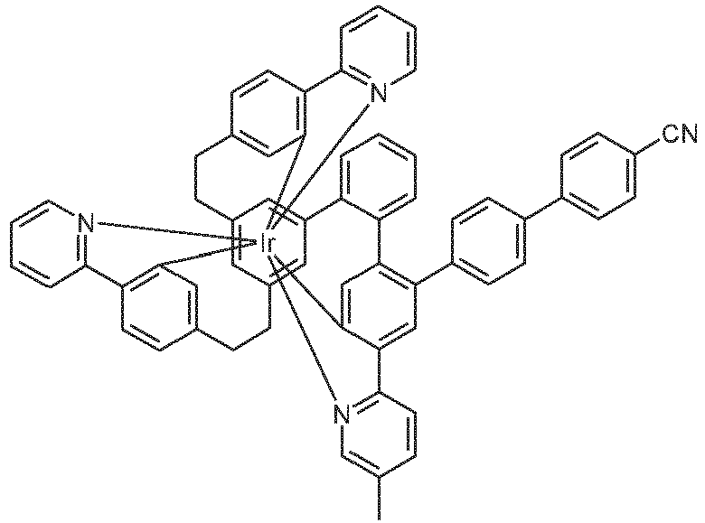

55 56 

57 58 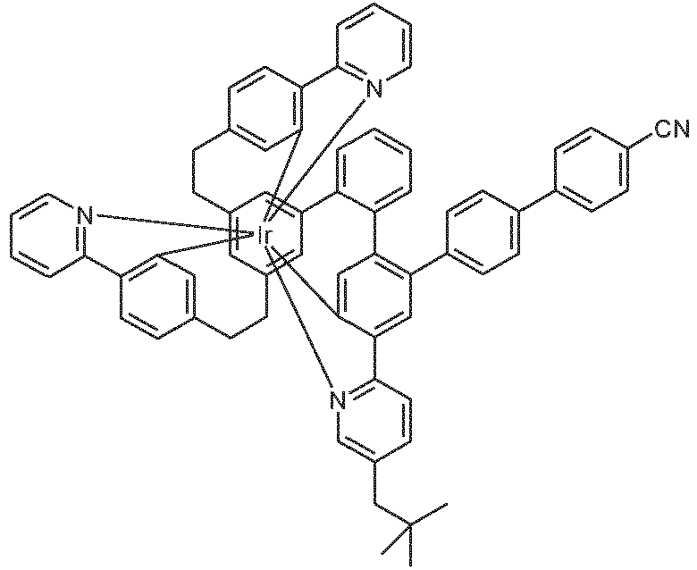

59 60 

61 62 

63 64 

65 66 

67 68 

69 70 

71 72 

73 74 

75 76 

77 78 

79 80 
81 82 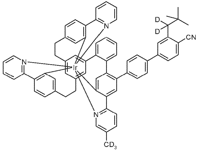

83 84 

85 86 

87 88 

89 90 

91 92 

93 94 

95 96 

97 98 

99 100 

101 102 

103 104 

105 106 

107 108 

109 110 

111 112 
113 114 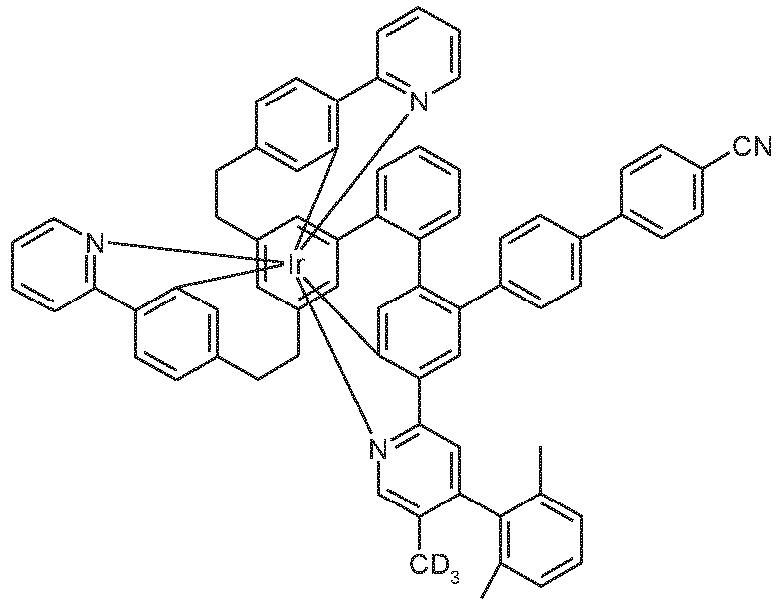

115 116 

117 118 
119 120 

121 122 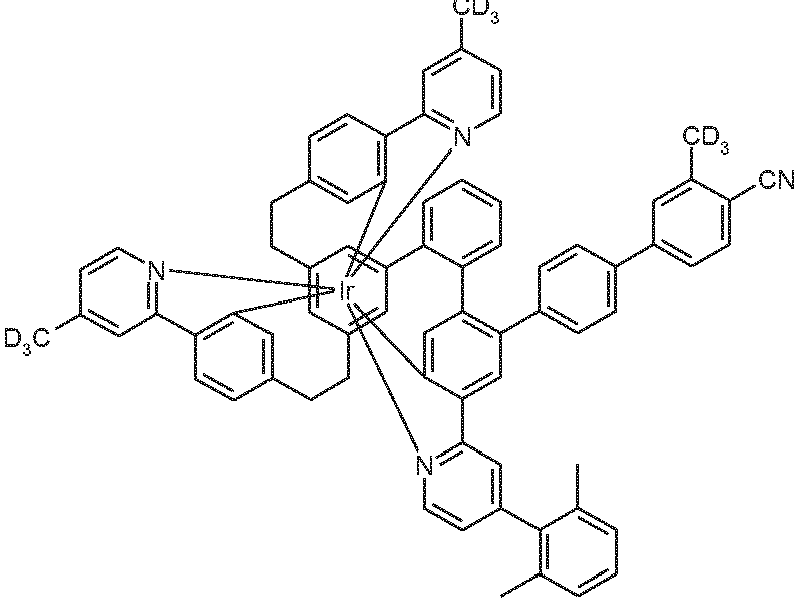

123 124 

125 126 

127 128 

129 130 

131 132 

133 134 
135 136 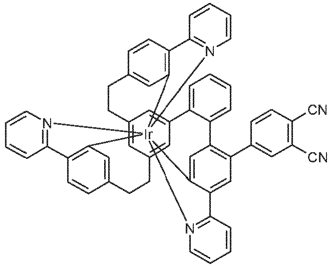
137 138 

139 140 

141 142 

143 144 

145 146 

147 148 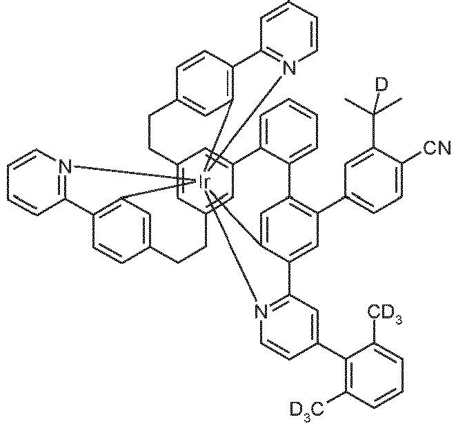

149 150 

151 152 

153 154 

155 156 

157 158 

159 160 

161 162 

163 164 

165 166 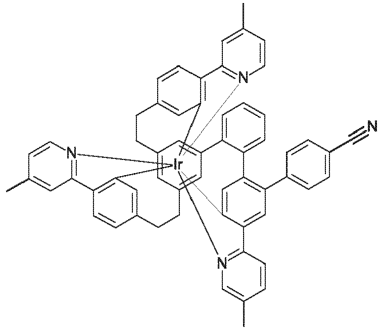

167 167 - Bei den erfindungsgemäßen Metallkomplexen handelt es sich um chirale Strukturen. Wenn zusätzlich auch der Ligand L chiral ist, ist die Bildung von Diastereomeren und mehreren Enantiomerenpaaren möglich. Die erfindungsgemäßen Komplexe umfassen dann sowohl die Mischungen der verschiedenen Diastereomere bzw. die entsprechenden Racemate, wie auch die einzelnen isolierten Diastereomere bzw. Enantiomere.
- Werden in der ortho-Metallierung Liganden mit zwei identischen Teilliganden eingesetzt, fällt üblicherweise ein racemisches Gemisch der C1-symmetrischen Komplexe, also des Δ- und des A-Enantiomers, an. Diese können durch gängige Methoden (Chromatographie an chiralen Materialien / Säulen oder Racemattrennung durch Kristallisation) getrennt werden, wie im Folgenden Schema dargestellt:

- Die Racemattrennung via fraktionierter Kristallisation von diastereomeren Salzpaaren kann nach üblichen Methoden erfolgen. Hierzu bietet es sich an, die neutralen Ir(III)-Komplexe zu oxidieren (z. B. mit Peroxiden, H2O2 oder elektrochemisch), die so erzeugten kationischen Ir(IV)-Komplexe mit dem Salz einer enantiomerenreinen, monoanionischen Base (chirale Base) zu versetzen, die so erzeugten diasteromeren Salze durch fraktionierte Kristallisation zu trennen und diese dann mit Hilfe eines Reduktionsmittels (z. B. Zink, Hydrazinhydrat, Ascorbinsäure, etc.) zu den enantiomerenreinen neutralen Komplex zu reduzieren, wie im Folgenden schematisch dargestellt:

- Daneben ist eine enantiomerenreine bzw. enantiomerenanreichernde Synthese durch Komplexierung in einem chiralen Medium (z. B. R- oder S-1,1-Binaphthol) möglich.
- Werden in der Komplexierung Liganden mit drei unterschiedlichen Teilliganden eingesetzt, fällt üblicherweise ein Diastereomerengemisch der Komplexe an, das durch gängige Methoden (Chromatographie, Kristallisation, etc.) getrennt werden kann.
- Enantiomerenreine C1-symmetrische Komplexe können auch gezielt synthetisiert werden, wie im folgenden Schema dargestellt. Dazu wird ein enantiomerenreiner, C1-symmetrischer Ligand dargestellt, komplexiert, das erhaltene Diasteroemerengemisch wird getrennt und anschließend wird die chirale Gruppe abgespalten.

- Die erfindungsgemäßen Verbindungen sind prinzipiell durch verschiedene Verfahren darstellbar. Generell wird hierzu ein Iridiumsalz mit dem entsprechenden freien Liganden umgesetzt.
- Daher ist ein weiterer Gegenstand der vorliegenden Erfindung ein Verfahren zur Herstellung der erfindungsgemäßen Verbindungen durch Umsetzung der entsprechenden freien Liganden mit Iridiumalkoholaten der Formel (Ir-1), mit Iridiumketoketonaten der Formel (Ir-2), mit Iridiumhalogeniden der Formel (Ir-3) oder mit Iridiumcarboxylaten der Formel (Ir-4),
Ir(OR)3 (Ir-1)

IrHaI3 (Ir-3)
Ir(OOCR)3 (Ir-4)
wobei R die oben angegebenen Bedeutungen hat, Hal = F, Cl, Br oder I ist und die Iridiumedukte auch als die entsprechenden Hydrate vorliegen können. Dabei steht R bevorzugt für eine Alkylgruppe mit 1 bis 4 C-Atomen. - Es können ebenfalls Iridiumverbindungen, die sowohl Alkoholat- und/oder Halogenid- und/oder Hydroxy- wie auch Ketoketonatreste tragen, verwendet werden. Diese Verbindungen können auch geladen sein. Entsprechende Iridiumverbindungen, die als Edukte besonders geeignet sind, sind in
WO 2004/085449 offenbart. Besonders geeignet sind [IrCl2(acac)2]-, beispielsweise Na[IrCl2(acac)2], Metallkomplexe mit Acetylacetonat-Derivaten als Ligand, beispielsweise Ir(acac)3 oder Tris(2,2,6,6-Tetramethylheptan-3,5-dionato)iridium, und IrCl3·xH2O, wobei x üblicherweise für eine Zahl zwischen 2 und 4 steht. - Die Synthese der Komplexe wird bevorzugt durchgeführt wie in
WO 2002/060910 und inWO 2004/085449 beschrieben. Besonders geeignet ist auch die Synthese in einer organischen Säure oder einer Mischung aus einer organischen Säure und einem organischen Lösemittel, wie in der noch nicht offen gelegten AnmeldungEP19187468.4 - Die Reaktionen können ohne Zusatz von Lösemitteln oder Schmelzhilfen in einer Schmelze der entsprechenden zu o-metallierenden Liganden durchgeführt werden. Gegebenenfalls können auch Lösemittel oder Schmelzhilfen zugesetzt werden. Geeignete Lösemittel sind protische oder aprotische Lösemittel, wie aliphatische und / oder aromatische Alkohle (Methanol, Ethanol, iso-Propanol, t-Butanol, etc.), Oligo- und Polyalkohole (Ethylenglykol, 1,2-Propandiol, Glycerin, etc.), Alkoholether (Ethoxyethanol, Diethylenglykol, Triethylenglycol, Polyethylenglykol, etc.), Ether (Di- und Triethylenglykoldimethylether, Diphenylether, etc.), aromatische, heteroaromatische und oder aliphatische Kohlenwasserstoffe (Toluol, Xylol, Mesitylen, Chlorbenzol, Pyridin, Lutidin, Chinolin, Isochinolin, Tridecan, Hexadecan, etc.), Amide (DMF, DMAC, etc.), Lactame (NMP), Sulfoxide (DMSO) oder Sulfone (Dimethylsulfon, Sulfolan, etc.). Geeignete Schmelzhilfen sind Verbindungen, die bei Rautemperatur fest vorliegen, jedoch beim Erwärmen der Reaktionsmischung schmelzen und die Reaktanden lösen, so dass eine homogene Schmelze entsteht. Besonders geeignet sind Biphenyl, m-Terphenyl, Triphenylen, R- oder S-Binaphthol oder auch das entsprechende Racemat, 1,2-, 1,3-, 1,4-Bisphenoxybenzol, Triphenylphosphinoxid, 18-Krone-6, Phenol, 1-Naphthol, Hydrochinon, etc.. Dabei ist die Verwendung von Hydrochinon besonders bevorzugt.
- Alternativ ist es auch möglich, zunächst den Komplex zu synthetisieren, der statt der Cyanophenyl- bzw. Cyanobiphenylgruppe eine reaktive Abgangsgruppe, beispielsweise Cl, Br, I oder ein Boronsäurederivat, enthält, zu synthetisieren und in einem nächsten Schritt die Cyanophenyl- bzw. Cyanobiphenylgruppe durch eine Kupplungsreaktion, beispielsweise eine Suzuki-Kupplung, einzuführen.
- Durch diese Verfahren, gegebenenfalls gefolgt von Aufreinigung, wie z. B. Umkristallisation oder Sublimation, lassen sich die erfindungsgemäßen Verbindungen gemäß Formel (1) in hoher Reinheit, bevorzugt mehr als 99 % (bestimmt mittels 1H-NMR und/oder HPLC) erhalten.
- Für die Verarbeitung der erfindungsgemäßen Iridiumkomplexe aus flüssiger Phase, beispielsweise durch Spin-Coating oder durch Druckverfahren, sind Formulierungen der erfindungsgemäßen Iridiumkomplexe erforderlich. Diese Formulierungen können beispielsweise Lösungen, Dispersionen oder Emulsionen sein. Es kann bevorzugt sein, hierfür Mischungen aus zwei oder mehr Lösemitteln zu verwenden. Geeignete und bevorzugte Lösemittel sind beispielsweise Toluol, Anisol, o-, m- oder p-Xylol, Methylbenzoat, Mesitylen, Tetralin, Veratrol, THF, Methyl-THF, THP, Chlorbenzol, Dioxan, Phenoxytoluol, insbesondere 3-Phenoxytoluol, (-)-Fenchon, 1,2,3,5-Tetramethylbenzol, 1,2,4,5-Tetramethylbenzol, 1-Methylnaphthalin, 2-Methylbenzothiazol, 2-Phenoxyethanol, 2-Pyrrolidinon, 3-Methylanisol, 4-Methylanisol, 3,4-Dimethylanisol, 3,5-Dimethylanisol, Acetophenon, α-Terpineol, Benzothiazol, Butylbenzoat, Cumol, Cyclohexanol, Cyclohexanon, Cyclohexylbenzol, Decalin, Dodecylbenzol, Ethylbenzoat, Indan, NMP, p-Cymol, Phenetol, 1,4-Diisopropylbenzol, Dibenzylether, Diethylenglycolbutylmethylether, Triethylenglycolbutylmethylether, Diethylenglycoldibutylether, Triethylenglycoldimethylether, Diethylenglycolmonobutylether, Tripropylenglycoldimethylether, Tetraethylenglycoldimethylether, 2-Isopropylnaphthalin, Pentylbenzol, Hexylbenzol, Heptylbenzol, Octylbenzol, 1,1-Bis(3,4-dimethylphenyl)ethan, Hexamethylindan, 2-Methylbiphenyl, 3-Methylbiphenyl, 1-Methylnaphthalin, 1-Ethylnaphthalin, Ethyloctanoat, Sebacinsäure-diethylester, Octyloctanoat, Heptylbenzol, Menthyl-isovalerat, Cyclohexylhexanoat oder Mischungen dieser Lösemittel.
- Ein weiterer Gegenstand der vorliegenden Erfindung ist daher eine Formulierung, enthaltend mindestens eine erfindungsgemäßen Verbindung und mindestens eine weitere Verbindung. Die weitere Verbindung kann beispielsweise ein Lösemittel sein, insbesondere eines der oben genannten Lösemittel oder eine Mischung dieser Lösemittel. Die weitere Verbindung kann aber auch eine weitere organische oder anorganische Verbindung sein, die ebenfalls in der elektronischen Vorrichtung eingesetzt wird, beispielsweise ein Matrixmaterial. Diese weitere Verbindung kann auch polymer sein.
- Die erfindungsgemäße Verbindung kann in einer elektronischen Vorrichtung als aktive Komponente, bevorzugt als Emitter in der emissiven Schicht einer organischen Elektrolumineszenzvorrichtung verwendet werden. Ein weiterer Gegenstand der vorliegenden Erfindung ist somit die Verwendung der erfindungsgemäßen Verbindungen in einer elektronischen Vorrichtung, insbesondere in einer organischen Elektrolumineszenzvorrichtung.
- Nochmals ein weiterer Gegenstand der vorliegenden Erfindung ist eine elektronische Vorrichtung enthaltend mindestens eine erfindungsgemäße Verbindung, insbesondere eine organische Elektrolumineszenzvorrichtung.
- Unter einer elektronischen Vorrichtung wird eine Vorrichtung verstanden, welche Anode, Kathode und mindestens eine Schicht enthält, wobei diese Schicht mindestens eine organische bzw. metallorganische Verbindung enthält. Die erfindungsgemäße elektronische Vorrichtung enthält also Anode, Kathode und mindestens eine Schicht, welche mindestens einen erfindungsgemäßen Iridiumkomplex enthält. Dabei sind bevorzugte elektronische Vorrichtungen ausgewählt aus der Gruppe bestehend aus organischen Elektrolumineszenzvorrichtungen (OLEDs, PLEDs), organischen integrierten Schaltungen (O-ICs), organischen Feld-Effekt-Transistoren (O-FETs), organischen Dünnfilmtransistoren (O-TFTs), organischen lichtemittierenden Transistoren (O-LETs), organischen Solarzellen (O-SCs), wobei hierunter sowohl rein organische Solarzellen wie auch farbstoffsensibilisierte Solarzellen verstanden werden, organischen optischen Detektoren, organischen Photorezeptoren, organischen Feld-Quench-Devices (O-FQDs), lichtemittierenden elektrochemischen Zellen (LECs), Sauerstoff-Sensoren oder organischen Laserdioden (O-Laser), enthaltend in mindestens einer Schicht mindestens eine erfindungsgemäße Verbindung. Verbindungen, die im Infraroten emittieren, eignen sich für den Einsatz in organischen Infrarot-Elektrolumineszenzvorrichtungen und Infrorot-Sensoren. Besonders bevorzugt sind organische Elektrolumineszenzvorrichtungen. Aktive Komponenten sind generell die organischen oder anorganischen Materialien, welche zwischen Anode und Kathode eingebracht sind, beispielsweise Ladungsinjektions-, Ladungstransport- oder Ladungsblockiermaterialien, insbesondere aber Emissionsmaterialien und Matrixmaterialien. Die erfindungsgemäßen Verbindungen zeigen besonders gute Eigenschaften als Emissionsmaterial in organischen Elektrolumineszenzvorrichtungen. Eine bevorzugte Ausführungsform der Erfindung sind daher organische Elektrolumineszenzvorrichtungen. Weiterhin können die erfindungsgemäßen Verbindungen zur Erzeugung von Singulett-Sauerstoff oder in der Photokatalyse eingesetzt werden.
- Die organische Elektrolumineszenzvorrichtung enthält Kathode, Anode und mindestens eine emittierende Schicht. Außer diesen Schichten kann sie noch weitere Schichten enthalten, beispielsweise jeweils eine oder mehrere Lochinjektionsschichten, Lochtransportschichten, Lochblockierschichten, Elektronentransportschichten, Elektroneninjektionsschichten, Exzitonenblockierschichten, Elektronenblockierschichten, Ladungserzeugungsschichten und/oder organische oder anorganische p/n-Übergänge. Dabei ist es möglich, dass eine oder mehrere Lochtransportschichten p-dotiert sind, beispielsweise mit Metalloxiden, wie MoO3 oder WO3, oder mit (per)fluorierten elektronenarmen Aromaten oder mit elektronenarmen Cyano-substituieren Heteroaromaten (z. B. gemäß
JP 4747558 JP 2006-135145 US 2006/0289882 ,WO 2012/095143 ), oder mit chinoiden Systemen (z. B. gemäßEP1336208 ) oder mit LewisSäuren, oder mit Boranen (z. B. gemäßUS 2003/0006411 ,WO 2002/051850 ,WO 2015/049030 ) oder mit Carboxylaten der Elemente der 3. , 4. oder 5. Hauptgruppe (WO 2015/018539 ) und/oder dass eine oder mehrere Elektronentransportschichten n-dotiert sind. - Ebenso können zwischen zwei emittierende Schichten Interlayers eingebracht sein, welche beispielsweise eine Exzitonen-blockierende Funktion aufweisen und/oder die Ladungsbalance in der Elektrolumineszenzvorrichtung steuern und/oder Ladungen erzeugen (Charge-Generation-Layer, z. B. in Schichtsystemen mit mehreren emittierenden Schichten, z. B. in weiß emittierenden OLED-Bauteilen) . Es sei aber darauf hingewiesen, dass nicht notwendigerweise jede dieser Schichten vorhanden sein muss.
- Dabei kann die organische Elektrolumineszenzvorrichtung eine emittierende Schicht enthalten, oder sie kann mehrere emittierende Schichten enthalten. Wenn mehrere Emissionsschichten vorhanden sind, weisen diese bevorzugt insgesamt mehrere Emissionsmaxima zwischen 380 nm und 750 nm auf, so dass insgesamt weiße Emission resultiert, d. h. in den emittierenden Schichten werden verschiedene emittierende Verbindungen verwendet, die fluoreszieren oder phosphoreszieren können. Insbesondere bevorzugt sind Dreischichtsysteme, wobei die drei Schichten blaue, grüne und orange oder rote Emission zeigen (für den prinzipiellen Aufbau siehe z. B.
WO 2005/011013 ) bzw. Systeme, welche mehr als drei emittierende Schichten aufweisen. Es kann sich auch um ein Hybrid-System handeln, wobei eine oder mehrere Schichten fluoreszieren und eine oder mehrere andere Schichten phosphoreszieren. Eine bevorzugte Ausführungsform sind Tandem-OLEDs. Weiß emittierende organische Elektrolumineszenzvorrichtungen können für Beleuchtungsanwendungen oder mit Farbfilter auch für Vollfarb-Displays verwendet werden. - In einer bevorzugten Ausführungsform der Erfindung enthält die organische Elektrolumineszenzvorrichtung die erfindungsgemäßen Verbindung als emittierende Verbindung in einer oder mehreren emittierenden Schichten.
- Wenn die erfindungsgemäße Verbindung als emittierende Verbindung in einer emittierenden Schicht eingesetzt wird, wird er bevorzugt in Kombination mit einem oder mehreren Matrixmaterialien eingesetzt. Die Mischung aus der erfindungsgemäßen Verbindung und dem Matrixmaterial enthält zwischen 0.1 und 99 Vol.-%, vorzugsweise zwischen 1 und 90 Vol.-%, besonders bevorzugt zwischen 3 und 40 Vol.-%, insbesondere zwischen 5 und 15 Vol.-% der erfindungsgemäßen Verbindung bezogen auf die Gesamtmischung aus Emitter und Matrixmaterial. Entsprechend enthält die Mischung zwischen 99.9 und 1 Vol.-%, vorzugsweise zwischen 99 und 10 Vol.-%, besonders bevorzugt zwischen 97 und 60 Vol.-%, insbesondere zwischen 95 und 85 Vol.-% des Matrixmaterials bezogen auf die Gesamtmischung aus Emitter und Matrixmaterial.
- Als Matrixmaterial können generell alle Materialien eingesetzt werden, die gemäß dem Stand der Technik hierfür bekannt sind. Bevorzugt ist das Triplett-Niveau des Matrixmaterials höher als das Triplett-Niveau des Emitters.
- Geeignete Matrixmaterialien für die erfindungsgemäßen Verbindungen sind Ketone, Phosphinoxide, Sulfoxide und Sulfone, z. B. gemäß
WO 2004/013080 ,WO 2004/093207 ,WO 2006/005627 oderWO 2010/006680 , Triarylamine, Carbazolderivate, z. B. CBP (N,N-Bis-carbazolylbiphenyl), m-CBP oder die inWO 2005/039246 ,US 2005/0069729 ,JP 2004/288381 EP 1205527 ,WO 2008/086851 oderUS 2009/0134784 offenbarten Carbazolderivate, Biscarbazolderivate, Indolocarbazolderivate, z. B. gemäßWO 2007/063754 oderWO 2008/056746 , Indenocarbazolderivate, z. B. gemäßWO 2010/136109 oderWO 2011/000455 , Azacarbazole, z. B. gemäßEP 1617710 ,EP 1617711 ,EP 1731584 ,JP 2005/347160 WO 2007/137725 , Silane, z. B. gemäßWO 2005/111172 , Azaborole oder Boronester, z. B. gemäßWO 2006/117052 , Diazasilolderivate, z. B. gemäßWO 2010/054729 , Diazaphospholderivate, z. B. gemäßWO 2010/054730 , Triazinderivate, z. B. gemäßWO 2010/015306 ,WO 2007/063754 oderWO 2008/056746 , Zinkkomplexe, z. B. gemäßEP 652273 WO 2009/062578 , Dibenzofuranderivate, z. B. gemäßWO 2009/148015 oderWO 2015/169412 , oder verbrückte Carbazolderivate, z. B. gemäßUS 2009/0136779 ,WO 2010/050778 ,WO 2011/042107 oderWO 2011/088877 . Für lösungsprozessierte OLEDs eignen sich als Matrixmaterialien auch Polymere, z. B. gemäßWO 2012/008550 oderWO 2012/048778 , Oligomere oder Dendrimere, z. B. gemäß Journal of Luminescence 183 (2017), 150-158. - Es kann auch bevorzugt sein, mehrere verschiedene Matrixmaterialien als Mischung einzusetzen, insbesondere mindestens ein elektronenleitendes Matrixmaterial und mindestens ein lochleitendes Matrixmaterial. Eine bevorzugte Kombination ist beispielsweise die Verwendung eines aromatischen Ketons, eines Triazin-Derivats, eines Pyrimidin-Derivats, eines Phosphinoxid-Derivats oder eines aromatischen Lactams mit einem Triarylamin-Derivat oder einem Carbazol-Derivat als gemischte Matrix für die erfindungsgemäße Verbindung. Ebenso bevorzugt ist die Verwendung einer Mischung aus einem ladungstransportierenden Matrixmaterial und einem elektrisch inerten Matrixmaterial (so genannter "wide bandgap host"), welches nicht bzw. nicht in wesentlichem Maße am Ladungstransport beteiligt ist, wie z. B. in
WO 2010/108579 oderWO 2016/184540 beschrieben. Ebenso bevorzugt ist die Verwendung von zwei elektronentransportierenden Matrixmaterialien, beispielsweise Triazinderivaten und Lactamderivaten, wie z. B. inWO 2014/094964 beschrieben. Nachfolgend sind Beispiele für Verbindungen abgebildet, die sich als Matrixmaterialien für die erfindungsgemäßen Verbindungen eignen. - Bevorzugte Biscarbazole, die als Matrixmaterialien für die erfindungsgemäßen Verbindungen eingesetzt werden können, sind die Strukturen der folgenden Formeln (10) und (11),


- Ar1
- ist gleich oder verschieden bei jedem Auftreten ein aromatisches oder heteroaromatisches Ringsystem mit 5 bis 40 aromatischen Ring-atomen, bevorzugt mit 6 bis 30 aromatischen Ringatomen, besonders bevorzugt mit 6 bis 24 aromatischen Ringatomen, welches jeweils mit einem oder mehreren Resten R', bevorzugt nicht-aromatischen Resten R', substituiert sein kann;
- A1
- ist NAr1, C(R')2, O oder S, bevorzugt C(R')2;
- R'
- ist gleich oder verschieden bei jedem Auftreten H, D, F, CN, eine Alkylgruppe mit 1 bis 10 C-Atomen, bevorzugt mit 1 bis 4 C-Atomen, oder ein aromatisches oder heteroaromatisches Ringsystem mit 5 bis 40 aromatischen Ringatomen, bevorzugt mit 6 bis 30 aromatischen Ringatomen, besonders bevorzugt mit 6 bis 24 aromatischen Ring-atomen, welches mit einem oder mehreren Substituenten, ausgewählt aus der Gruppe bestehend aus D, F, CN oder einer Alkylgruppe mit 1 bis 10 C-Atomen, bevorzugt mit 1 bis 4 C-Atomen, substituiert sein kann.
- Bevorzugte Ausführungsformen der Verbindungen der Formeln (10) bzw. (11) sind die Verbindungen der folgenden Formeln (10a) bzw. (11a),

- Bevorzugte Dibenzofuran-Derivate sind die Verbindungen der folgenden Formel (12),

- Bevorzugte Carbazolamine sind die Strukturen der folgenden Formeln (13), (14) und (15),

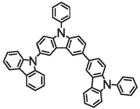
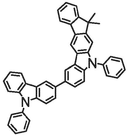
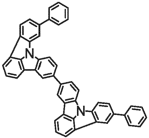
- Beispiele für geeignete lochleitende Matrixmaterialien sind die in der folgenden Tabelle abgebildeten Verbindungen.


H1 H2 H3 


H4 H5 H6 

H7 H8 H9 

H10 H11 H12 


H13 H14 H15 


H16 H17 H18 


H19 H20 H21 


H22 H23 H24 


H25 H26 H27 


H28 H29 H30 


H31 H32 H33 


H34 H35 H36 


H37 H38 H39 


H40 H41 H42 


H43 H44 H45 

H46 H47 H48 


H49 H50 H51 


H52 H53 H54 


H55 H56 H57 - Bevorzugte Triazin- bzw. Pyrimidinderivate, welche als Mischung zusammen mit den erfindungsgemäßen Verbindungen eingesetzt werden können, sind die Verbindungen der folgenden Formeln (16) und (17),

- Besonders bevorzugt sind die Triazinderivate der Formel (16).
- In einer bevorzugten Ausführungsform der Erfindung ist Ar1 in den Formeln (16) und (17) bei jedem Auftreten gleich oder verschieden ein aromatisches oder heteroaromatisches Ringsystem mit 6 bis 30 aromatischen Ringatomen, insbesondere mit 6 bis 24 aromatischen Ringatomen, das durch einen oder mehrere Reste R' substituiert sein kann.
- Beispiele für geeignete elektronentransportierende Verbindungen, welche als Matrixmaterialien zusammen mit den erfindungsgemäßen Verbindungen eingesetzt werden können, sind die in der folgenden Tabelle abgebildeten Verbindungen.


E1 E2 E3 


E4 E5 E6 


E7 E8 E9 


E10 E11 E12 


E13 E14 E15 


E16 E17 E18 


E19 E20 E21 

E22 E23 E24 


E25 E26 E27 


E28 E29 E30 


E31 E32 E33 

E34 E35 E36 


E37 E38 E39 


E40 E41 E42 

E43 E44 E45 

E46 E47 E48 


E49 E50 E51 


E52 E53 E54 


E55 E56 E57 


E58 E59 E60 


E61 E62 E63 

E64 E65 E66 


E67 E68 E69 


E70 E71 E72 


E73 E74 E75 


E76 E77 E78 


E79 E80 E81 


E81 E82 E83 


E84 E85 E86 

E87 E88 E89 


E90 E91 E92 


E93 E94 E95 


E96 E97 E98 
E99 E100 E101 
E102 E103 E104 


E105 E106 E107 


E108 E109 E110 


E111 E112 E113 


E114 E115 E116 


E117 E118 E119 


E120 E121 E122 


E123 E124 E125 


E126 E127 E128 

E129 E130 E131 


E132 E133 E134 


E135 E136 E137 

E138 E139 E140 


E141 E142 E143 


E144 E145 E146 


E147 E148 E149 


E150 E151 E152 


E153 E154 E155 


E156 E157 E158 

E159 E160 E161 


E162 E163 E164 

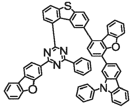
E165 E166 E167 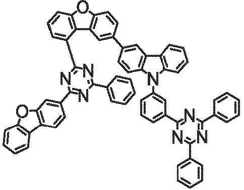


E168 E169 E170 


E171 E172 E173 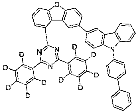


E174 E175 E176 

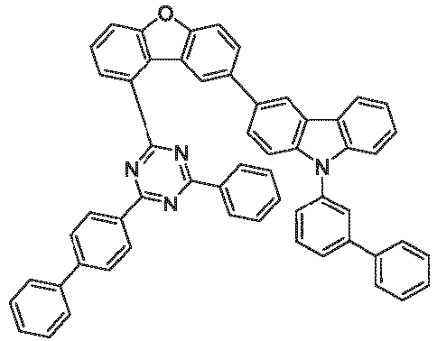
E177 E178 E179 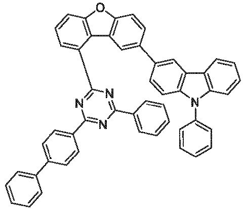
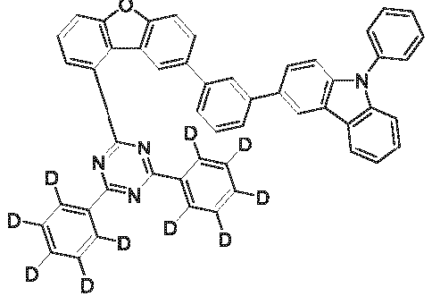

E180 E181 E182 


E183 E184 E185 


E186 E187 E188 


E189 E190 E191 
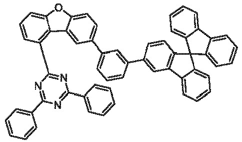
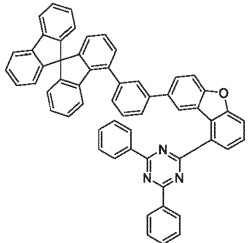
E192 E193 E194 

E195 E196 E197 

E198 E199 E200 


E201 E202 E203 


E204 E205 E206 


E207 E208 E209 


E210 E211 E212 


E213 E214 E215 

E216 E217 E218 


E219 E220 E221 


E222 E223 E224 


E225 E226 E227 


E228 E229 E230 


E231 E232 E233 


E234 E235 E236 


E237 E238 E239 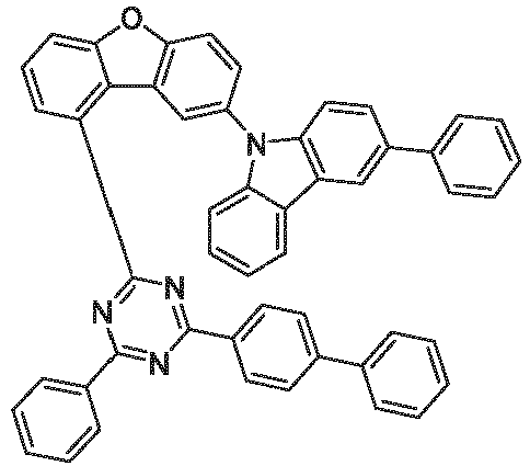


E240 E241 E242 


E243 E244 E245 


E246 E247 E248 


E249 E250 E251 


E252 E253 E254 
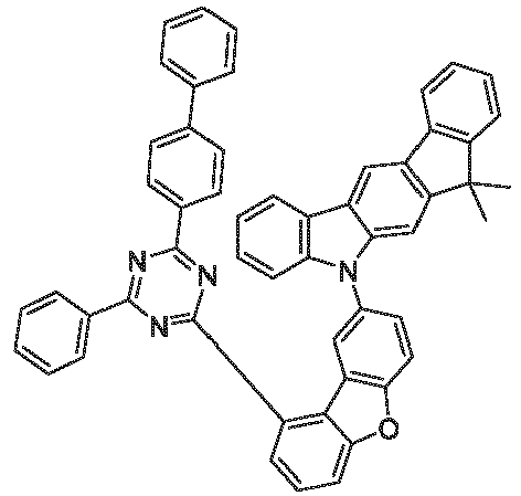

E255 E256 E257 


E258 E259 E260 


E261 E262 E263 


E264 E265 E266 

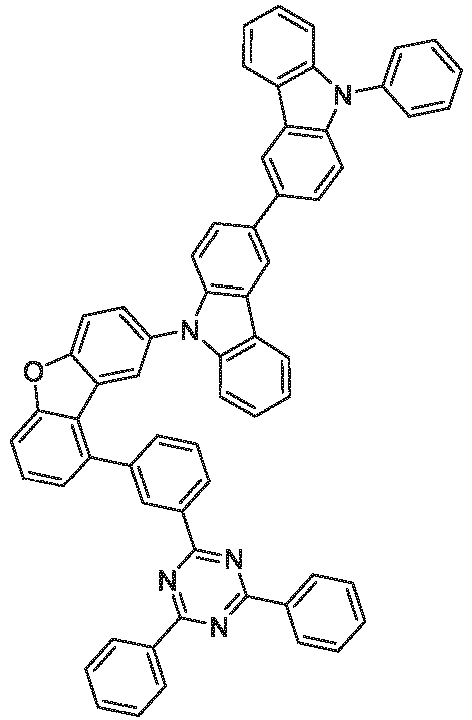
E267 E268 E269 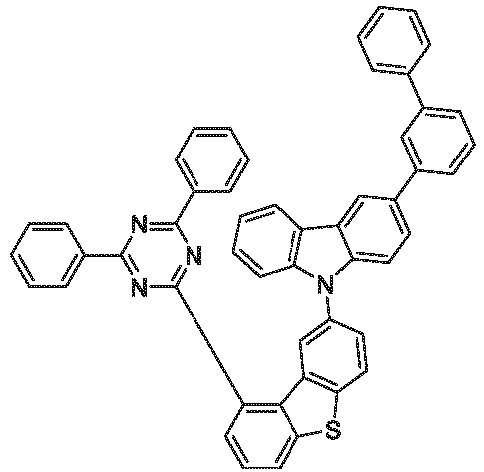


E270 E271 E272 
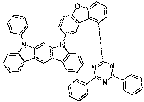

E273 E274 E275 


E276 E277 E278 

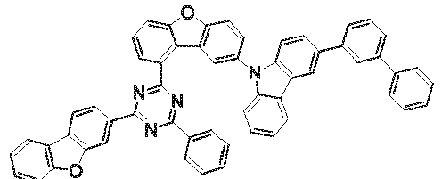
E279 E280 E281 

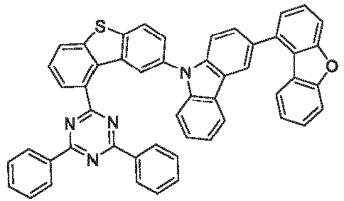
E282 E283 E284 


E285 E286 E287 

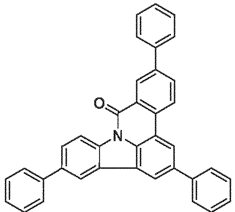
E288 E289 E300 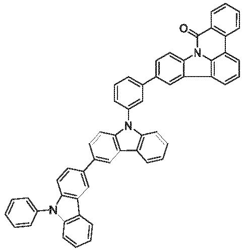


E301 E302 E303 - Als Kathode sind Metalle mit geringer Austrittsarbeit, Metalllegierungen oder mehrlagige Strukturen aus verschiedenen Metallen bevorzugt, wie beispielsweise Erdalkalimetalle, Alkalimetalle, Hauptgruppenmetalle oder Lanthanoide (z. B. Ca, Ba, Mg, Al, In, Mg, Yb, Sm, etc.). Weiterhin eignen sich Legierungen aus einem Alkali- oder Erdalkalimetall und Silber, beispielsweise eine Legierung aus Magnesium und Silber. Bei mehrlagigen Strukturen können auch zusätzlich zu den genannten Metallen weitere Metalle verwendet werden, die eine relativ hohe Austrittsarbeit aufweisen, wie z. B. Ag, wobei dann in der Regel Kombinationen der Metalle, wie beispielsweise Mg/Ag, Ca/Ag oder Ba/Ag verwendet werden. Es kann auch bevorzugt sein, zwischen einer metallischen Kathode und dem organischen Halbleiter eine dünne Zwischenschicht eines Materials mit einer hohen Dielektrizitätskonstante einzubringen. Hierfür kommen beispielsweise Alkalimetall- oder Erdalkalimetallfluoride, aber auch die entsprechenden Oxide oder Carbonate in Frage (z. B. LiF, Li2O, BaF2, MgO, NaF, CsF, Cs2CO3, etc.). Ebenso kommen hierfür organische Alkalimetallkomplexe in Frage, z. B. Liq (Lithiumchinolinat). Die Schichtdicke dieser Schicht beträgt bevorzugt zwischen 0.5 und 5 nm.
- Als Anode sind Materialien mit hoher Austrittsarbeit bevorzugt. Bevorzugt weist die Anode eine Austrittsarbeit größer 4.5 eV vs. Vakuum auf. Hierfür sind einerseits Metalle mit hohem Redoxpotential geeignet, wie beispielsweise Ag, Pt oder Au. Es können andererseits auch Metall/Metalloxid-Elektroden (z. B. Al/Ni/NiOx, Al/PtOx) bevorzugt sein. Für einige Anwendungen muss mindestens eine der Elektroden transparent oder teiltransparent sein, um entweder die Bestrahlung des organischen Materials (O-SC) oder die Auskopplung von Licht (OLED/PLED, O-LASER) zu ermöglichen. Bevorzugte Anodenmaterialien sind hier leitfähige gemischte Metalloxide. Besonders bevorzugt sind Indium-Zinn-Oxid (ITO) oder Indium-Zink-Oxid (IZO). Bevorzugt sind weiterhin leitfähige, dotierte organische Materialien, insbesondere leitfähige dotierte Polymere, z. B. PEDOT, PANI oder Derivate dieser Polymere. Bevorzugt ist weiterhin, wenn auf die Anode ein p-dotiertes Lochtransportmaterial als Lochinjektionsschicht aufgebracht wird, wobei sich als p-Dotanden Metalloxide, beispielsweise MoO3 oder WO3, oder (per)fluorierte elektronenarme Aromaten eignen. Weitere geeignete p-Dotanden sind HAT-CN (Hexacyano-hexaazatriphenylen) oder die Verbindung NPD9 von Novaled. Eine solche Schicht vereinfacht die Lochinjektion in Materialien mit einem tiefen HOMO, also einem betragsmäßig großen HOMO.
- In den weiteren Schichten können generell alle Materialien verwendet werden, wie sie gemäß dem Stand der Technik für die Schichten verwendet werden, und der Fachmann kann ohne erfinderisches Zutun jedes dieser Materialien in einer elektronischen Vorrichtung mit den erfindungsgemäßen Materialien kombinieren.
- Geeignete Ladungstransportmaterialien, wie sie in der Lochinjektions- bzw. Lochtransportschicht bzw. Elektronenblockierschicht oder in der Elektronentransportschicht der erfindungsgemäßen organischen Elektrolumineszenzvorrichtung verwendet werden können, sind beispielsweise die in Y. Shirota et al., Chem. Rev. 2007, 107(4), 953-1010 offenbarten Verbindungen oder andere Materialien, wie sie gemäß dem Stand der Technik in diesen Schichten eingesetzt werden. Bevorzugt sind als Lochtransportmaterialien, die in einer Lochtransport-, Lochinjektions- oder Elektronenblockierschicht in der erfindungsgemäßen Elektrolumineszenzvorrichtung verwendet werden können, Indenofluorenamin-Derivate (z. B. gemäß
WO 06/122630 WO 06/100896 EP 1661888 offenbarten Aminderivate, Hexaazatriphenylenderivate (z. B. gemäßWO 01/049806 US 5,061,569 ), die inWO 95/09147 WO 08/006449 WO 07/140847 WO 2012/034627 ,WO2014/056565 ), Fluoren-Amine (z. B. gemäßEP 2875092 ,EP 2875699 undEP 2875004 ), Spiro-Dibenzopyran-Amine (z. B.EP 2780325 ) und Dihydroacridin-Derivate (z. B. gemäßWO 2012/150001 ). - Die Vorrichtung wird entsprechend (je nach Anwendung) strukturiert, kontaktiert und schließlich hermetisch versiegelt, da sich die Lebensdauer derartiger Vorrichtungen bei Anwesenheit von Wasser und/oder Luft drastisch verkürzt.
- Weiterhin bevorzugt ist eine organische Elektrolumineszenzvorrichtung, dadurch gekennzeichnet, dass eine oder mehrere Schichten mit einem Sublimationsverfahren beschichtet werden. Dabei werden die Materialien in Vakuum-Sublimationsanlagen bei einem Anfangsdruck von üblicherweise kleiner 10-5 mbar, bevorzugt kleiner 10-6 mbar aufgedampft. Es ist auch möglich, dass der Anfangsdruck noch geringer oder noch höher ist, beispielsweise kleiner 10-7 mbar.
- Bevorzugt ist ebenfalls eine organische Elektrolumineszenzvorrichtung, dadurch gekennzeichnet, dass eine oder mehrere Schichten mit dem OVPD (Organic Vapour Phase Deposition) Verfahren oder mit Hilfe einer Trägergassublimation beschichtet werden. Dabei werden die Materialien bei einem Druck zwischen 10-5 mbar und 1 bar aufgebracht. Ein Spezialfall dieses Verfahrens ist das OVJP (Organic Vapour Jet Printing) Verfahren, bei dem die Materialien direkt durch eine Düse aufgebracht und so strukturiert werden (z. B. M. S. Arnold et al., Appl. Phys. Lett. 2008, 92, 053301).
- Weiterhin bevorzugt ist eine organische Elektrolumineszenzvorrichtung, dadurch gekennzeichnet, dass eine oder mehrere Schichten aus Lösung, wie z. B. durch Spincoating, oder mit einem beliebigen Druckverfahren, wie z. B. Siebdruck, Flexodruck, Offsetdruck oder Nozzle-Printing, besonders bevorzugt aber LITI (Light Induced Thermal Imaging, Thermotransferdruck) oder Ink-Jet Druck (Tintenstrahldruck), hergestellt werden. Hierfür sind lösliche Verbindungen nötig, welche beispielsweise durch geeignete Substitution erhalten werden.
- Die organische Elektrolumineszenzvorrichtung kann auch als Hybridsystem hergestellt werden, indem eine oder mehrere Schichten aus Lösung aufgebracht werden und eine oder mehrere andere Schichten aufgedampft werden. So ist es beispielsweise möglich, eine emittierende Schicht enthaltend einen erfindungsgemäßen Metallkomplex und ein Matrixmaterial aus Lösung aufzubringen und darauf eine Lochblockierschicht und/oder eine Elektronentransportschicht im Vakuum aufzudampfen.
- Diese Verfahren sind dem Fachmann generell bekannt und können von ihm ohne Probleme auf organische Elektrolumineszenzvorrichtungen enthaltend Verbindungen gemäß Formel (1) bzw. die oben aufgeführten bevorzugten Ausführungsformen angewandt werden.
- Die erfindungsgemäßen elektronischen Vorrichtungen, insbesondere organische Elektrolumineszenzvorrichtungen, zeichnen sich gegenüber dem Stand der Technik dadurch aus, dass sie eine signifikant verbesserte Lebensdauer aufweisen gegenüber vergleichbaren Strukturen, die an dem Phenyl- bzw. Biphenylsubstituenten keine Cyanogruppe aufweisen. Dabei erhält man gleichzeitig eine leichte Verbesserung der Effizienz und der Spannung.
- Die Erfindung wird durch die nachfolgenden Beispiele näher erläutert, ohne sie dadurch einschränken zu wollen. Der Fachmann kann aus den Schilderungen ohne erfinderisches Zutun weitere erfindungsgemäße elektronische Vorrichtungen herstellen und somit die Erfindung im gesamten beanspruchten Bereich ausführen.
- Die nachfolgenden Synthesen werden, sofern nicht anders angegeben, unter einer Schutzgasatmosphäre in getrockneten Lösungsmitteln durchgeführt. Die Metallkomplexe werden zusätzlich unter Ausschluss von Licht bzw. unter Gelblicht gehandhabt. Die Lösungsmittel und Reagenzien können z. B. von Sigma-ALDRICH bzw. ABCR bezogen werden. Die jeweiligen Angaben in eckigen Klammern bzw. die zu einzelnen Verbindungen angegebenen Nummern beziehen sich auf die CAS-Nummern der literaturbekannten Verbindungen. Bei Verbindungen, die mehrere tautomere, isomere, diastereomere und enantiomere Formen aufweisen können, wird stellvertretend eine Form gezeigt.
-

- Ein Gemisch aus 81.8 g (100 mmol) 2-(4-{2-[3-(2'-{[Trifluormethansulfonyl]-4-yl}-4'-(pyridin-2-yl)-[1,1'-biphenyl]-2-yl)-5-{2-[4-(pyridin-2-yl)-phenyl]ethyl}-phenyl]ethyl}phenyl)pyridin [2375157-32-5], 16.2 g (110 mmol) 4-Cyanophenylboronsäure [126747-14-6], 53.1 g (250 mmol) Trikaliumphosphat, 800 ml THF und 200 ml Wasser wird unter kräftigem Rühren mit 1.64 g (4 mmol) S-Phos und dann mit 449 mg (2 mmol) Palladium(II)acetat versetzt und 12 h unter Rückfluss erhitzt. Nach Erkalten trennt man die wässrige Phase ab, engt die organische Phase im Vakuum weitgehend ein, nimmt den Rückstand in 500 ml Ethylacetat auf, wäscht die organische Phase zweimal mit je 300 ml Wasser, einmal mit 2%iger, wässriger N-Acetylcystein-Lösung, einmal mit 300 ml gesättigter Kochsalzlösung und trocknet über Magnesiumsulfat. Man filtriert vom Trockenmittel über ein mit Ethylacetat vorgeschlämmtes Kieselgel-Bett ab, wäscht mit Ethylacetat nach, engt das Filtrat zur Trockene ein und kristallisiert den Rückstand aus ca. 200 ml Acetonitril in der Siedehitze um. Ausbeute: 50.2 g (65 mmol), 65 %; Reinheit: ca. 98 %ig nach 1H-NMR.
- Analog können folgende Verbindungen dargestellt werden.
Bsp. Edukte Produkt Ausbeute L2 2375157-34-7 
70 % 126747-14-6 L3 2375157-36-9 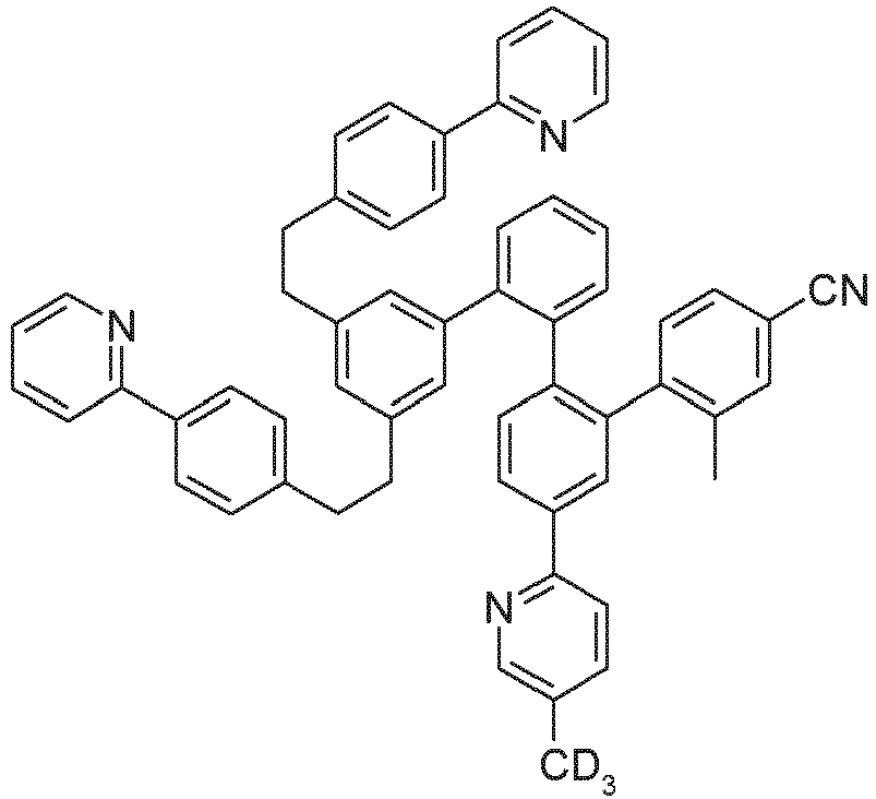
67 % 313546-18-8 L4 2375157-38-1 
63 % 856255-58-8 L5 2375157-40-5 
69 % 1384855-53-1 L6 2375157-32-5 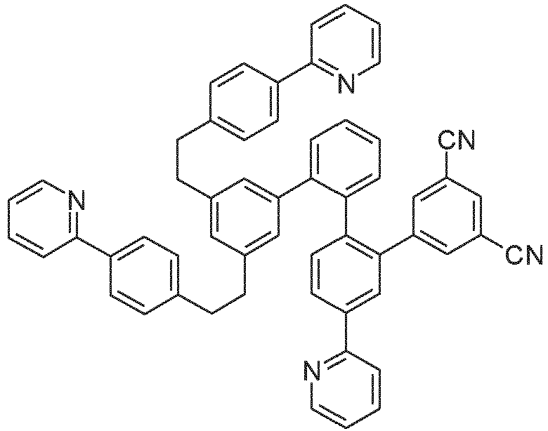
55 % 1212021-54-9 L7 2375157-36-9 
58 % 1212021-54-9 L-Ref3 2375157-36-9 
72 % 98-80-6 L100 2375157-32-5 
76 % 406482-73-3 L101 2375157-34-7 
73 % 406482-73-3 L102 2375157-36-9 
75 % 406482-73-3 L103 2375157-40-5 
70 % 406482-73-3 L104 2375157-42-7 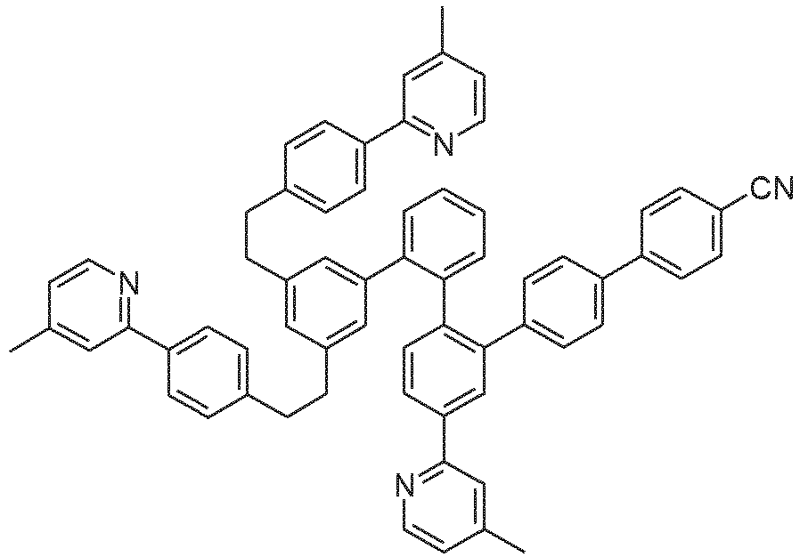
68 % 406482-73-3 L105 2375157-44-9 
63 % 406482-73-3 L106 2375157-34-7 
68 % 1800587-08-9 L107 2375157-34-7 
65 % 2380354-21-0 L108 2375157-34-7 
67 % 1615713-15-9 L109 2375157-42-7 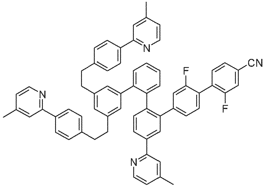
60 % 2291171-92-9 L110 2375157-40-5 
1352715-67-3 L111 2375157-36-9 
68 % 2242884-56-4 L112 2375157-44-9 
61 % 2242884-55-3 -

- Ein Gemisch aus 7.71 g (10 mmol) des Liganden L1, 4.90 g (10 mmol) Tris-acetylacetonato-iridium(III) [15635-87-7] und 120 g Hydrochinon [123-31-9] werden in einem 1000 mL Zweihalsrundkolben mit einem glasummantelten Magnetkern vorgelegt. Der Kolben wird mit einem Wasserabscheider (für Medien geringerer Dichte als Wasser) und einem Luftkühler mit Argonüberlagerung versehen. Der Kolben wird in einer Metallheizschale platziert. Die Apparatur wird über die Argonüberlagerung von oben her 15 min. mit Argon gespült, wobei man das Argon aus dem Seitenhals des Zweihalskolbens ausströmen lässt. Über den Seitenhals des Zweihalskolbens führt man ein glasummanteltes Pt-100 Thermoelement in den Kolben ein und platziert das Ende kurz oberhalb des Magnetrührkerns. Dann wird die Apparatur mit mehreren lockeren Wicklungen von Haushaltsaluminiumfolie thermisch isoliert, wobei die Isolation bis zur Mitte des Steigrohres des Wasserabscheiders geführt wird. Dann wird die Apparatur schnell mit einem Laborheizrührwerk auf 240-245 °C, gemessen am Pt-100 Thermofühler, der in die aufgeschmolzene, gerührte Reaktionsmischung eintaucht, erhitzt. Während der nächsten 1 h wird das Reaktionsgemisch bei 240-245 °C gehalten, wobei wenig Kondensat abdestilliert und sich im Wasserabscheider sammelt. Nach 1 h lässt man auf ca. 190 °C abkühlen, entfernt die Heizschale und tropft dann 100 ml Ethylenglycol zu. Nach Erkalten auf 100 °C tropft man langsam 400 ml Methanol zu. Die so erhaltene gelbe Suspension wird über eine Umkehrfritte filtriert, der gelbe Feststoff wird dreimal mit 50 ml Methanol gewaschen und dann im Vakuum getrocknet. Der so erhaltene Feststoff wird in 200 ml Dichlormethan gelöst und über 600 g mit Dichlormethan vorgeschlämmtes Kieselgel (Säulendurchmesser ca. 10 cm) unter Luft- und Lichtausschluss filtriert, wobei dunkle Anteile am Start liegen bleiben. Die Kernfraktion wird herausgeschnitten und am Rotationsverdampfer eingeengt, wobei gleichzeitig kontinuierlich MeOH bis zur Kristallisation zugetropft wird. Nach Absaugen, Waschen mit wenig MeOH und Trocknen im Vakuum erfolgt die weitere Reinigung des gelben Produkts durch viermalige kontinuierliche Heißextraktion mit Dichlormethan/i-Propanol 1:1 (vv) und dann viermalige Heißextraktion mit Dichlormethan/Acetonitril (Vorlagemenge jeweils ca. 200 ml, Extraktionshülse: Standard Soxhletthülsen aus Cellulose der Fa. Whatman) unter sorgfältigem Luft- und Lichtausschluss. Über das Verhältnis Dichlormethan (Niedersieder und Gutlöser) : i-Propanol bzw. Acetonitril (Hochsieder und Schlechtlöser) kann der Verlust in die Mutterlauge eingestellt werden. Typischerweise sollte er 3-6 Gew.-% der eingesetzten Menge betragen. Es können zur Heißextraktion auch andere Lösungsmittel wie Toluol, Xylol, Essigester, Butylacetat, etc. verwendet werden. Abschließend wird das Produkt im Hochvakuum bei p ~ 10-6 mbar und T ~ 330 - 430 °C fraktioniert sublimiert. Ausbeute: 4.91 g (5.1 mmol), 51 %; Reinheit: > 99.9 %ig nach HPLC.
- Die Metallkomplexe fallen üblicherweise als 1:1 Mischung der A- und Δ-Isomere/Enantiomere an. Die im Folgenden aufgeführte Abbildungen von Komplexen zeigen üblicherweise nur ein Isomer. Werden Liganden mit drei verschiedenen Teilliganden eingesetzt, bzw. werden chirale Liganden als Racemat eingesetzt, fallen die abgeleiteten Metallkomplexe als Diastereomerenmischung an. Diese können durch fraktionierte Kristallisation oder chromatographisch getrennt werden, z. B. mit einem Säulenautomaten (CombiFlash der Fa. A. Semrau). Werden chirale Liganden enantiomerenrein eingesetzt, fallen die abgeleiteten Metallkomplexe als Diastereomerenmischung an, deren Trennung durch fraktionierte Kristallisation oder Chromatographie zu reinen Enantiomeren führt. Die getrennten Diastereomeren bzw. Enantiomeren können wie oben beschrieben z. B. durch Heißextraktion weiter gereinigt werden.
- Analog können folgende Verbindungen dargestellt werden:
Bsp. Ligand Produkt Variante / Extraktionsmittel Ausbeute Ir(L2) L2 
55 % Ir(L3) L3 
53 % Ir(L4) L4 
64 % Ir(L5) L5 
65 % Ir(L6) L6 
57 % Ir(L7) L7 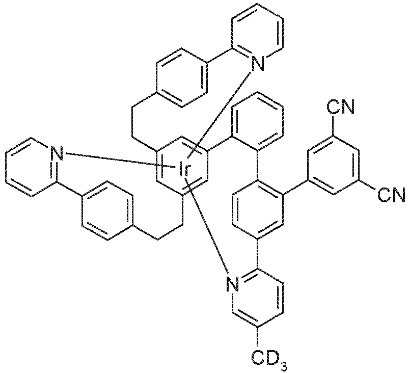
53 % Ir(L-Ref3) L-Ref3 
78 % Ir(L100) L100 
57 % Ir(L101) L101 
53 % Ir(L102) L102 
56 % Ir(L103) L103 
59 % Ir(L104) L104 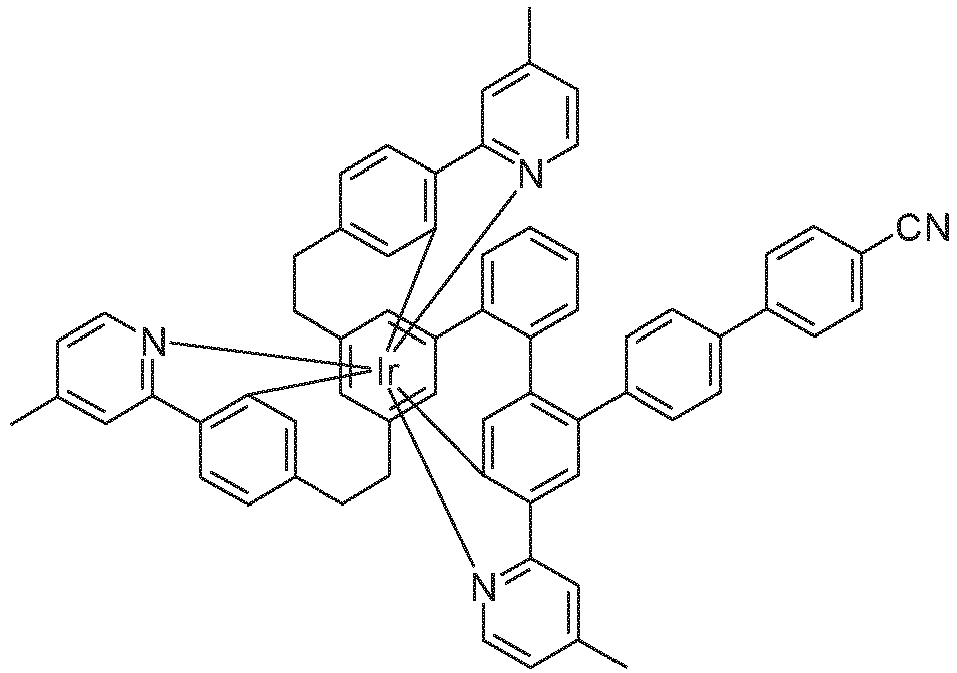
61 % Ir(L105) L105 
56 % Ir(L106) L106 
60 % Ir(L107) L107 
64 % Ir(L108) L108 
57 % Ir(L109) L109 
61 % Ir(L110) L110 
60 % Ir(L111) L111 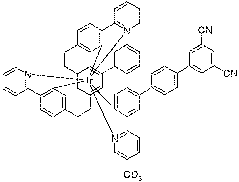
55 % Ir(L112) L112 
49 % - 1 mmol des sauberen Komplexes (Reinheit > 99.9%) mit x Methyl-/Mehylengruppen und x = 1 - 6 wird durch Erhitzen auf ca. 180 °C in 50 ml DMSO-d6 (Deuterierungsgrad > 99.8 %) gelöst. Die Lösung wird 5 min. bei 180 °C gerühert. Man lässt die Lösung auf 80 °C erkalten und versetzt die Lösung zügig unter gutem Rühren mit einer Mischung von 5 ml Methanol-d1 (Deuterierungsgrad > 99.8 %) und 10 ml DMSO-d6 (Deuterierungsgrad > 99.8 %), in welchem 0.3 mmol Natriumhydrid gelöst wurden. Man rührt die klare gelb-orange Lösung bei 80 °C weitere 30 min. für Komplexe mit Methyl-/Methylengruppen para zum Pyridin-Stickstoff bzw. weitere 6h für Komplexe mit Methyl-/Methylengruppen meta zum Pyridin-Stickstoff nach, kühlt dann mit Hilfe eines Kaltwasserbades ab, versetzt tropfenweise ab ~ 60 °C mit 20 ml 1N DCI in D2O, lässt auf Raumtemperatur erkalten, rührt 5 h nach, saugt vom Feststoff ab und wäscht diesen dreimal mit je 10 ml H2O/MeOH (1:1, vv) und dann dreimal mit je 10 ml MeOH und trocknet im Vakuum. Der Feststoff wird in DCM gelöst, die Lösung über Kieselgel filtriert, das Filtrat wird im Vakuum eingeengt, gleichzeitig tropfenweise mit MeOH versetzt und dadaurch zur Kristallisation gebracht. Abschließend wird fraktioniert sublimiert wie unter "C: Darstellung der Metallkomplexe, Variante A" beschrieben. Ausbeute typischerweise 80-90%, Deuterierungsgrad > 95%.
- Analog können folgende deuterierte Komplexe dargestellt werden:
Bsp. Edukt Produkt Ausbeute Ir(L103-D9) Ir(L103) 
78 % Ir(L104-D9) Ir(L104) 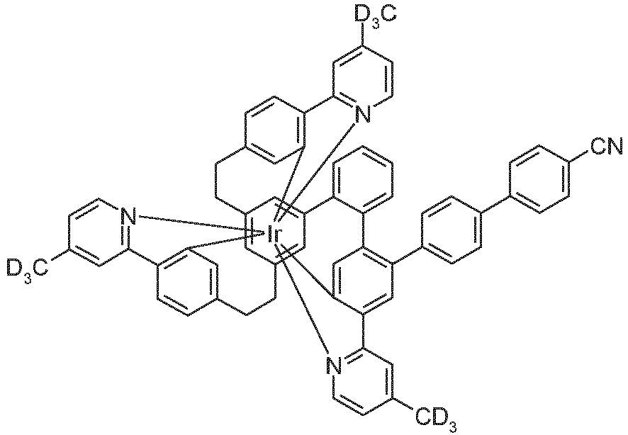
85 % - Die Herstellung von erfindungsgemäßen OLEDs sowie OLEDs nach dem Stand der Technik erfolgt nach einem allgemeinen Verfahren gemäß
WO 2004/058911 , das auf die hier beschriebenen Gegebenheiten (Schichtdickenvariation, verwendete Materialien) angepasst wird. - Gereinigte Glasplättchen (Reinigung in Miele Laborspülmaschine, Reiniger Merck Extran), die mit strukturiertem ITO (Indium Zinn Oxid) der Dicke 50 nm beschichtet sind, werden 15 Minuten bei 250 °C unter Stickstoff ausgeheizt. Die vorgereinigten ITO-Substrate werden einem Zwei-Gas-Plasmaprozess (Sauerstoff gefolgt von Argon) unterzogen, um die ITO-Oberfälche final zu reinigen und die ITO-Austrittsarbeit anzupassen. Diese beschichteten Glasplättchen bilden die Substrate, auf welche die OLEDs aufgebracht werden. Alle Materialien werden durch thermische Vakuumdeposition aufgebracht. Dabei besteht die Emissionsschicht immer aus mindestens einem Matrixmaterial (Hostmaterial, Wirtsmaterial) und einem emittierenden Dotierstoff (Dotand, Emitter), der dem Matrixmaterial bzw. den Matrixmaterialien durch Co-Verdampfung in einem bestimmten Volumenanteil beigemischt wird. Eine Angabe wie M1:M2:Ir-Emitter (29.5%:58.5:12%) bedeutet hierbei, dass das Material M1 in einem Volumenanteil von 29.5%, M2 in einem Volumenanteil von 58.5% und Ir-Emitter in einem Volumenanteil von 12% in der Schicht vorliegt. Analog besteht auch die Elektronentransportschicht aus einer Mischung zweier Materialien.
- Die OLEDs haben prinzipiell folgenden Schichtaufbau: ITO-Substrat / Lochinjektionsschicht 1 (HIL1) bestehend aus HTM1 dotiert mit 5 % NDP-9 (kommerziell erhältlich von der Fa. Novaled), 20 nm / Lochstransportschicht 1 (HTL1) bestehend aus HTM1, 40 nm / Lochtransportschicht 2 (HTL2), 20 nm / Emissionsschicht (EML), s. Tabelle 1 / Lochblockierschicht (HBL), s. Tabelle 1 / Elektronentransportschicht (ETL), s. Tabelle 1 / Elektroneninjektionsschicht (EIL), s. Tabelle 1 / 100 nm dicke Aluminiumschicht als Kathode. Die zur Herstellung der OLEDs verwendeten Materialien sind in Tabelle 3 gezeigt.
- Die OLEDs werden standardmäßig charakterisiert. Hierfür werden die Elektrolumineszenzspektren, die Stromeffizienz (gemessen in cd/A), die Leistungseffizienz (gemessen in Im/W) und die externe Quanteneffizienz (EQE, gemessen in Prozent) in Abhängigkeit der Leuchtdichte, berechnet aus Strom-Spannungs-Leuchtdichte-Kennlinien (IUL-Kennlinien) unter Annahme einer lambertschen Abstrahlcharakteristik sowie die Lebensdauer bestimmt. Die Elektrolumineszenzspektren werden bei einer Leuchtdichte von 1000 cd/m2 bestimmt und daraus die CIE 1931 x und y Farbkoordinaten berechnet. Als Lebensdauer LD90 wird die Zeit definiert, nach der die Leuchtdichte bei Betrieb mit einer Starthelligkeit von 10000 cd/m2 auf 90% der Startleuchtdichte abgesunken ist. Die OLEDs können initital auch bei anderen Startleuchtdichten betrieben werden. Die Werte für die Lebensdauer können dann mit Hilfe dem Fachmann bekannten Umrechnungsformeln auf eine Angabe für andere Startleuchtdichten umgerechnet werden.
- Die erfindungsgemäßen Verbindungen lassen sich unter anderem als phosphoreszierende Emittermaterialien in der Emissionsschicht in OLEDs einsetzen. Als Vergleich gemäß dem Stand der Technik werden die Iridiumverbindungen gemäß Tabelle 3 verwendet. Die Ergebnisse der OLEDs sind in Tabelle 2 zusammengefasst.
- Wie man an den Ergebnissen erkennt, führen die erfindungsgemäßen Verbindungen bei Verwendung als Emitter in einer OLED zu einer leichten Verbesserung von Effizienz und Spannung bei einer gleichzeitigen signifikanten Verbesserung der Lebensdauer, beispielsweise einer Verbesserung der Lebensdauer um 60% im Fall des erfindungsgemäßen Komplexes Ir(L100) im Vergleich zu dem Komplex Ir-Ref.1 gemäß dem Stand der Technik, der die gleiche Struktur wie Ir(L100) aufweist, jedoch keine Cyanogruppe am Biphenylsubstituenten enthält.
Tabelle 1: Aufbau der OLEDs Bsp. EML Dicke HBL Dicke ETL Dicke EIL Ref.D1 M1:M2:Ir-Ref.1 (29.5%:58.5%:12%) 40 nm HBL1 5nm ETM1:ETM2 (50%:50%) 30 nm ETM2 1 nm Ref.D2 M1:M2:Ir-Ref.2 (29.5%:58.5%:12%) 40 nm HBL1 5nm ETM1:ETM2 (50%:50%) 30 nm ETM2 1 nm Ref.D3 M1:M2:Ir(L-Ref3) (29.5%:58.5%:12%) 40 nm HBL1 5nm ETM1:ETM2 (50%:50%) 30 nm ETM2 1 nm D1 M1:M2:Ir(L1) (29.5%:58.5%:12%) HBL1 5nm ETM1:ETM2 (50%:50%) ETM2 1 nm 40 nm 30 nm D2 M1:M2:Ir(L2) (29.5%:58.5%:12%) 40 nm HBL1 5nm ETM1:ETM2 (50%:50%) 30 nm ETM2 1 nm D3 M1:M2:Ir(L3) (29.5%:58.5%:12%) 40 nm HBL1 5nm ETM1:ETM2 (50%:50%) 30 nm ETM2 1 nm D4 M1:M2:Ir(L4) (29.5%:58.5%:12%) 40 nm HBL1 5nm ETM1:ETM2 (50%:50%) 30 nm ETM2 1 nm D5 M1:M2:Ir(L5) (29.5%:58.5%:12%) 40 nm HBL1 5nm ETM1:ETM2 (50%:50%) 30 nm ETM2 1 nm D6 M1:M2:Ir(L6) (29.5%:58.5%:12%) 40 nm HBL1 5nm ETM1:ETM2 (50%:50%) 30 nm ETM2 1 nm D7 M1:M2:Ir(L7) (29.5%:58.5%:12%) 40 nm HBL1 5nm ETM1:ETM2 (50%:50%) 30 nm ETM2 1 nm D100 M1:M2:Ir(L100) (29.5%:58.5%:12%) 40 nm HBL1 5nm ETM1:ETM2 (50%:50%) 30 nm ETM2 1 nm D101 M1:M2:Ir(L101) (29.5%:58.5%:12%) 40 nm HBL1 5nm ETM1:ETM2 (50%:50%) 30 nm ETM2 1 nm D102 M1:M2:Ir(L102) (29.5%:58.5%:12%) 40 nm HBL1 5nm ETM1:ETM2 (50%:50%) 30 nm ETM2 1 nm D103 M1:M2:Ir(L103) (29.5%:58.5%:12%) 40 nm HBL1 5nm ETM1:ETM2 (50%:50%) 30 nm ETM2 1 nm D103-D M1:M2:Ir(L103-D) (29.5%:58.5%:12%) 40 nm HBL1 5nm ETM1:ETM2 (50%:50%) 30 nm ETM2 1 nm D104 M1:M2:Ir(L104) (29.5%:58.5%:12%) 40 nm HBL1 5nm ETM1:ETM2 (50%:50%) 30 nm ETM2 1 nm D104-D M1:M2:Ir(L104-D) (29.5%:58.5%:12%) 40 nm HBL1 5nm ETM1:ETM2 (50%:50%) 30 nm ETM2 1 nm D105 M1:M2:Ir(L105) (46.0%:46%:8%) 40 nm HBL1 5nm ETM1:ETM2 (50%:50%) 30 nm ETM2 1 nm D106 M1:M2:Ir(L106) (29.5%:58.5%:12%) 40 nm HBL1 5nm ETM1:ETM2 (50%:50%) 30 nm ETM2 1 nm D107 M1:M2:Ir(L107) (29.5%:58.5%:12%) 40 nm HBL1 5nm ETM1:ETM2 (50%:50%) 30 nm ETM2 1 nm D108 M1:M2:Ir(L108) (29.5%:58.5%:12%) 40 nm HBL1 5nm ETM1:ETM2 (50%:50%) 30 nm ETM2 1 nm D109 M1:M2:Ir(L109) (29.5%:58.5%:12%) 40 nm HBL1 5nm ETM1:ETM2 (50%:50%) 30 nm ETM2 1 nm D110 M1:M2:Ir(L110) HBL1 ETM1:ETM2 ETM2 (29.5%:58.5%:12%) 40 nm 5nm (50%:50%) 30 nm 1 nm D110 M1:M2:Ir(L111) (29.5%:58.5%:12%) 40 nm HBL1 5nm ETM1:ETM2 (50%:50%) 30 nm ETM2 1 nm Tabelle 2: Ergebnisse der Vakuum-prozessierten OLEDs (Eff., EQE, Spannung, CIE bei 1000 cd/m2; Lebensdauer LD90 bei 10000 cd/m2) Bsp. Eff. [cd/A] Eff. [lm/W] EQE [%] Spannung [V] CIE [x/y] LD90 [h] Ref.D1 93.2 88.8 24.8 3.30 0.363/0.614 1040 Ref.D2 89.6 94.7 24.1 3.18 0.301/0.650 790 Ref.D3 82.9 86.4 21.6 3.02 0.347/0.626 650 D1 87.1 97.9 23.6 2.80 0.350/0.617 730 D2 90.2 103.2 23.4 2.75 0.346/0.623 840 D3 89.2 96.8 23.3 2.90 0.320/0.664 710 D4 91.2 104.4 23.5 2.74 0.348/0.621 860 D5 90.0 101.8 23.4 2.73 0.350/0.620 700 D6 84.9 100.7 22.8 2.64 0.327/0.637 630 D7 84.4 99.7 22.7 2.66 0.324/0.642 630 D100 95.2 91.8 25.2 3.26 0.363/0.614 1660 D101 96.6 96.3 25.8 3.15 0.340/0.627 1700 D102 96.0 96.1 25.8 3.17 0.341/0.624 2000 D103 90.9 101.3 24.5 2.82 0.348/0.621 1370 D103-D 89.4 99.8 24.5 2.85 0.346/0.619 1580 D104 85.5 90.6 22.8 2.96 0.339/0.628 1230 D104-D 84.7 89.8 22.7 2.95 0.338/0.626 1460 D105 93.2 97.1 24.8 3.02 0.333/0.634 1280 D106 92.4 92.3 24.4 3.11 0.334/0.635 1130 D107 93.1 93.5 24.5 3.09 0.336/0.632 1100 D108 93.2 94.0 24.5 3.18 0.332/0.633 1060 D109 90.1 94.0 23.0 3.10 0.332/0.633 1130 D110 90.7 100.7 24.4 2.80 0.346/0.624 1220 D111 97.5 99.2 25.9 3.01 0.331/0.636 2000 Tabelle 3: Strukturformeln der verwendeten Materialien 
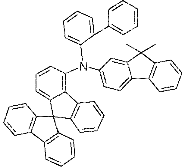
HTM1 [1365840-52-3] HTM2 [1450933-44-4] 

M1 M2 [1643479-47-3] [1822310-86-0] 

HBL1 [1955543-57-3] ETM1 [1819335-36-8] 

ETM2[25387-93-3] Ir-Ref.1 [2375153-43-6] 
Ir-Ref.2 WO2019/158453
Claims (13)
- Verbindung der Formel (1),
Ir(L) Formel (1)
wobei der Ligand L eine Struktur der folgenden Formel (2) aufweist: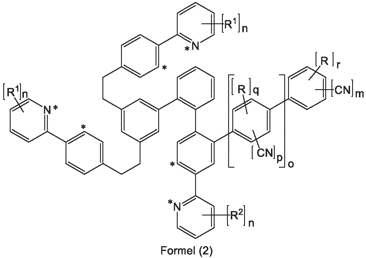 wobei der Ligand L über die mit * gekennzeichneten Positionen an das Iridiumatom koordiniert und wobei die nicht explizit eingezeichneten H-Atome auch durch D ersetzt sein können und wobei für die verwendeten Symbole und Indizes gilt:R ist gleich oder verschieden bei jedem Auftreten H, D, F, eine lineare Alkylgruppe mit 1 bis 10 C-Atomen oder eine verzweigte oder cyclische Alkylgruppe mit 3 bis 10 C-Atomen, wobei die Alkylgruppe jeweils auch deuteriert sein kann; dabei können zwei benachbarte Reste R miteinander ein Ringsystem bilden;R1 ist gleich oder verschieden bei jedem Auftreten H, D, eine lineare Alkylgruppe mit 1 bis 10 C-Atomen oder eine verzweigte oder cyclische Alkylgruppe mit 3 bis 10 C-Atomen, wobei die Alkyl- gruppe jeweils auch deuteriert sein kann; dabei können zwei benachbarte Reste R1 miteinander ein Ringsystem bilden;R2 ist gleich oder verschieden bei jedem Auftreten H, D, eine lineare Alkylgruppe mit 1 bis 10 C-Atomen, eine verzweigte oder cyclische Alkylgruppe mit 3 bis 10 C-Atomen, wobei die Alkylgruppe jeweils auch deuteriert sein kann, oder eine Phenyl- oder Biphenylgruppe, die jeweils durch ein oder mehrere Alkylgruppen mit 1 bis 10 C-Atomen substituiert sein kann, wobei die Phenyl- bzw. Biphenylgruppe bzw. die Alkylgruppen jeweils auch deuteriert sein können; dabei können zwei benachbarte Reste R2 miteinander ein Ringsystem bilden;m ist 1, 2 oder 3;n ist bei jedem Auftreten gleich oder verschieden 0, 1, 2 oder 3;o ist 0 oder 1;p ist 0, 1 oder 2;q ist 0, 1 oder 2;r ist 0, 1 oder 2.
 - Verbindung nach Anspruch 1, dadurch gekennzeichnet, dass für m = 1 der Ligand L für eine Struktur der Formel (3a) steht, für m = 2 der Ligand L für eine Struktur der Formel (3b) oder (3c) steht und für m = 3 der Ligand L für eine Struktur der Formel (3d) oder (3e) steht,


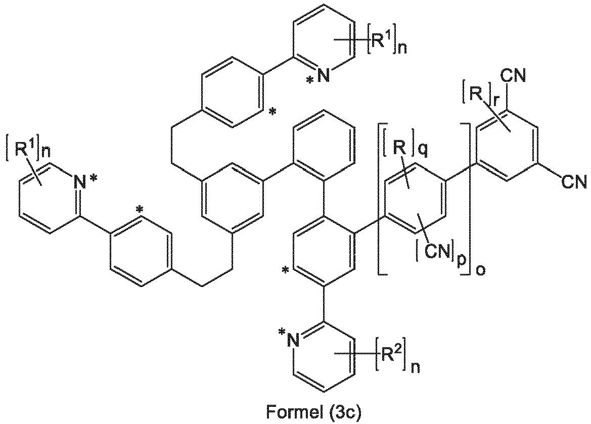

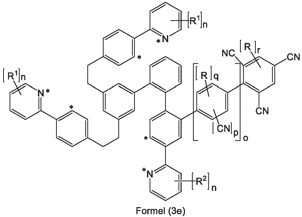
- Verbindung nach Anspruch 1 oder 2, dadurch gekennzeichnet, dass der Ligand L für o = 1 und p = 1 eine Struktur der Formel (4a) aufweist aund dass der Ligand L für o = 1 und p = 2 eine Struktur der Formel (4b) aufweist,


- Verbindung nach einem oder mehreren der Ansprüche 1 bis 3,dadurch gekennzeichnet, dass der Ligand L eine Struktur der Formel (7) aufweist,
 wobei die nicht explizit eingezeichneten H-Atome auch durch D ersetzt sein können und die Symbole und Indizes die in Anspruch 1 genannten Bedeutungen aufweisen.
 - Verbindung nach einem oder mehreren der Ansprüche 1 bis 4, dadurch gekennzeichnet, dass für die Substituenten gilt:R ist gleich oder verschieden bei jedem Auftreten ausgewählt aus der Gruppe bestehend aus D, einer linearen Alkylgruppe mit 1 bis 6 C-Atomen oder einer verzweigten oder cyclischen Alkylgruppe mit 3 bis 6 C-Atomen, wobei die Alkylgruppen jeweils auch deuteriert sein können;R1 ist gleich oder verschieden bei jedem Auftreten ausgewählt aus der Gruppe bestehend aus D, einer linearen Alkylgruppe mit 1 bis 6 C-Atomen oder einer verzweigten oder cyclischen Alkylgruppe mit 3 bis 6 C-Atomen, wobei die Alkylgruppen jeweils auch deuteriert sein können; dabei können zwei benachbarte Reste R1 miteinander ein Ringsystem bilden;R2 ist gleich oder verschieden bei jedem Auftreten ausgewählt aus der Gruppe bestehend aus D, einer linearen Alkylgruppe mit 1 bis 6 C-Atomen oder einer verzweigten oder cyclischen Alkylgruppe mit 3 bis 6 C-Atomen, wobei die Alkylgruppen jeweils auch deuteriert sein können, oder eine optional deuterierte Phenylgruppe, die durch ein oder mehrere optional deuterierte Alkylgruppen mit 1 bis 4 C-Atomen substituiert sein kann; dabei können zwei benachbarte Reste R2 miteinander ein Ringsystem bilden.
- Verbindung nach einem oder mehreren der Ansprüche 1 bis 5, dadurch gekennzeichnet, dass für die Symbole und Indizes gilt:R ist gleich oder verschieden bei jedem Auftreten ausgewählt aus der Gruppe bestehend aus D, einer linearen Alkylgruppe mit 1 bis 4 C-Atomen oder einer verzweigten Alkylgruppe mit 3 oder 4 C-Atomen, wobei die Alkylgruppen jeweils auch deuteriert sein können;R1 ist gleich oder verschieden bei jedem Auftreten ausgewählt aus der Gruppe bestehend aus D, einer linearen Alkylgruppe mit 1 bis 4 C-Atomen oder einer verzweigten Alkylgruppe mit 3 oder 4 C-Atomen, wobei die Alkylgruppen jeweils auch deuteriert sein können; dabei können zwei benachbarte Reste R1 miteinander ein Ringsystem bilden;R2 ist gleich oder verschieden bei jedem Auftreten ausgewählt aus der Gruppe bestehend aus D, einer linearen Alkylgruppe mit 1 bis 4 C-Atomen oder einer verzweigten Alkylgruppe mit 3 oder 4 C-Atomen, wobei die Alkylgruppen jeweils auch deuteriert sein können, oder eine optional deuterierte Phenylgruppe, die durch ein oder mehrere optional deuterierte Alkylgruppen mit 1 bis 4 C-Atomen substituiert sein kann; dabei können zwei benachbarte Reste R2 miteinander ein Ringsystem bilden;m ist 1 oder 2;n ist bei jedem Auftreten gleich oder verschieden 0, 1 oder 2;o ist 1; oder o ist 0 oder 1, wenn n am gleichen Liganden = 1 ist und R2 für eine Phenylgruppe steht;p ist 0 oder 1;q ist 0 oder 1;r ist 0 oder 1.
- Verbindung nach einem oder mehreren der Ansprüche 1 bis 6, dadurch gekennzeichnet, dass der Ligand L eine Struktur der Formel (8) aufweist,

- Verbindung nach einem oder mehreren der Ansprüche 1 bis 7, dadurch gekennzeichnet, dass der Ligand L eine Struktur der Formel (9) aufweist,

- Verfahren zur Herstellung einer Verbindung nach einem oder mehreren der Ansprüche 1 bis 8 durch Umsetzung des freien Liganden L mit Iridiumalkoholaten der Formel (Ir-1), mit Iridiumketoketonaten der Formel (Ir-2), mit Iridiumhalogeniden der Formel (Ir-3) oder mit Iridiumcarboxylaten der Formel (Ir-4) oder mit Iridiumverbindungen, die sowohl Alkoholat- und/oder Halogenid- und/oder Hydroxywie auch Ketoketonatreste tragen,
Ir(OR)3 (Ir-1)

IrHaI3 (Ir-3)
Ir(OOCR)3 (Ir-4)
wobei R die in Anspruch 1 angegebenen Bedeutungen hat, Hal = F, Cl, Br oder I ist und die Iridiumedukte auch als die entsprechenden Hydrate vorliegen können. - Formulierung, enthaltend mindestens eine Verbindung nach einem oder mehreren der Ansprüche 1 bis 8 und mindestens ein Lösemittel.
- Verwendung einer Verbindung nach einem oder mehreren der Ansprüche 1 bis 8 in einer elektronischen Vorrichtung.
- Elektronische Vorrichtung enthaltend mindestens eine Verbindung nach einem oder mehreren der Ansprüche 1 bis 8.
- Elektronische Vorrichtung nach Anspruch 12, wobei es sich um eine organische Elektrolumineszenzvorrichtung handelt, dadurch gekennzeichnet, dass die Verbindung nach einem oder mehreren der Ansprüche 1 bis 8 als emittierende Verbindung in einer oder mehreren emittierenden Schichten eingesetzt wird.
Applications Claiming Priority (2)
| Application Number | Priority Date | Filing Date | Title |
|---|---|---|---|
| EP20198952 | 2020-09-29 | ||
| PCT/EP2021/076429 WO2022069380A1 (de) | 2020-09-29 | 2021-09-27 | Mononukleare tripodale hexadentate iridium komplexe zur verwendung in oleds |
Publications (2)
| Publication Number | Publication Date |
|---|---|
| EP4222155A1 EP4222155A1 (de) | 2023-08-09 |
| EP4222155B1 true EP4222155B1 (de) | 2025-06-11 |
Family
ID=72670568
Family Applications (1)
| Application Number | Title | Priority Date | Filing Date |
|---|---|---|---|
| EP21782984.5A Active EP4222155B1 (de) | 2020-09-29 | 2021-09-27 | Mononukleare tripodale hexadentate iridium komplexe zur verwendung in oleds |
Country Status (5)
| Country | Link |
|---|---|
| US (1) | US20230331754A1 (de) |
| EP (1) | EP4222155B1 (de) |
| KR (1) | KR20230074754A (de) |
| CN (1) | CN116113676B (de) |
| WO (1) | WO2022069380A1 (de) |
Citations (1)
| Publication number | Priority date | Publication date | Assignee | Title |
|---|---|---|---|---|
| EP3752512A1 (de) * | 2018-02-13 | 2020-12-23 | Merck Patent GmbH | Metallkomplexe |
Family Cites Families (67)
| Publication number | Priority date | Publication date | Assignee | Title |
|---|---|---|---|---|
| US5061569A (en) | 1990-07-26 | 1991-10-29 | Eastman Kodak Company | Electroluminescent device with organic electroluminescent medium |
| JP3295088B2 (ja) | 1993-09-29 | 2002-06-24 | 出光興産株式会社 | 有機エレクトロルミネッセンス素子 |
| JPH07133483A (ja) | 1993-11-09 | 1995-05-23 | Shinko Electric Ind Co Ltd | El素子用有機発光材料及びel素子 |
| KR100377321B1 (ko) | 1999-12-31 | 2003-03-26 | 주식회사 엘지화학 | 피-형 반도체 성질을 갖는 유기 화합물을 포함하는 전기소자 |
| US6660410B2 (en) | 2000-03-27 | 2003-12-09 | Idemitsu Kosan Co., Ltd. | Organic electroluminescence element |
| DE10058578C2 (de) | 2000-11-20 | 2002-11-28 | Univ Dresden Tech | Lichtemittierendes Bauelement mit organischen Schichten |
| DE50104149D1 (de) | 2000-12-22 | 2004-11-18 | Covion Organic Semiconductors | Bor- oder aluminium-spiroverbindungen, deren verwendung in elekronikindustrie |
| DE10104426A1 (de) | 2001-02-01 | 2002-08-08 | Covion Organic Semiconductors | Verfahren zur Herstellung von hochreinen, tris-ortho-metallierten Organo-Iridium-Verbindungen |
| US6597012B2 (en) | 2001-05-02 | 2003-07-22 | Junji Kido | Organic electroluminescent device |
| ITRM20020411A1 (it) | 2002-08-01 | 2004-02-02 | Univ Roma La Sapienza | Derivati dello spirobifluorene, loro preparazione e loro uso. |
| EP1578885A2 (de) | 2002-12-23 | 2005-09-28 | Covion Organic Semiconductors GmbH | Organisches elektrolumineszenzelement |
| JP4411851B2 (ja) | 2003-03-19 | 2010-02-10 | コニカミノルタホールディングス株式会社 | 有機エレクトロルミネッセンス素子 |
| DE10314102A1 (de) | 2003-03-27 | 2004-10-14 | Covion Organic Semiconductors Gmbh | Verfahren zur Herstellung von hochreinen Organo-Iridium-Verbindungen |
| EP1717291A3 (de) | 2003-04-15 | 2007-03-21 | Merck Patent GmbH | Mischungen von organischen, zur Emission befähigten Halbleitern und Maxtrixmaterialien, deren Verwendung und diese Mischungen enthaltende Elektronikbauteile |
| EP1617711B1 (de) | 2003-04-23 | 2016-08-17 | Konica Minolta Holdings, Inc. | Organisches elektrolumineszenzbauelement und anzeige |
| DE10333232A1 (de) | 2003-07-21 | 2007-10-11 | Merck Patent Gmbh | Organisches Elektrolumineszenzelement |
| US7795801B2 (en) | 2003-09-30 | 2010-09-14 | Konica Minolta Holdings, Inc. | Organic electroluminescent element, illuminator, display and compound |
| US7332232B2 (en) | 2004-02-03 | 2008-02-19 | Universal Display Corporation | OLEDs utilizing multidentate ligand systems |
| US7790890B2 (en) | 2004-03-31 | 2010-09-07 | Konica Minolta Holdings, Inc. | Organic electroluminescence element material, organic electroluminescence element, display device and illumination device |
| KR100787425B1 (ko) | 2004-11-29 | 2007-12-26 | 삼성에스디아이 주식회사 | 페닐카바졸계 화합물 및 이를 이용한 유기 전계 발광 소자 |
| DE102004023277A1 (de) | 2004-05-11 | 2005-12-01 | Covion Organic Semiconductors Gmbh | Neue Materialmischungen für die Elektrolumineszenz |
| JP4862248B2 (ja) | 2004-06-04 | 2012-01-25 | コニカミノルタホールディングス株式会社 | 有機エレクトロルミネッセンス素子、照明装置及び表示装置 |
| ITRM20040352A1 (it) | 2004-07-15 | 2004-10-15 | Univ Roma La Sapienza | Derivati oligomerici dello spirobifluorene, loro preparazione e loro uso. |
| TWI382079B (zh) | 2004-07-30 | 2013-01-11 | Sanyo Electric Co | 有機電場發光元件及有機電場發光顯示裝置 |
| JP4747558B2 (ja) | 2004-11-08 | 2011-08-17 | ソニー株式会社 | 表示素子用有機材料および表示素子 |
| JP2006135145A (ja) | 2004-11-08 | 2006-05-25 | Sony Corp | 表示素子用有機材料および表示素子 |
| JP4358884B2 (ja) | 2005-03-18 | 2009-11-04 | 出光興産株式会社 | 芳香族アミン誘導体及びそれを用いた有機エレクトロルミネッセンス素子 |
| EP1888706B1 (de) | 2005-05-03 | 2017-03-01 | Merck Patent GmbH | Organische elektrolumineszenzvorrichtung und in deren herstellung verwendete boronsäure- und borinsäure-derivate |
| DE102005023437A1 (de) | 2005-05-20 | 2006-11-30 | Merck Patent Gmbh | Verbindungen für organische elektronische Vorrichtungen |
| EP1956022B1 (de) | 2005-12-01 | 2012-07-25 | Nippon Steel Chemical Co., Ltd. | Verbindung für organisches elektrolumineszentes element und organisches elektrolumineszentes element |
| DE102006025777A1 (de) | 2006-05-31 | 2007-12-06 | Merck Patent Gmbh | Neue Materialien für organische Elektrolumineszenzvorrichtungen |
| DE102006025846A1 (de) | 2006-06-02 | 2007-12-06 | Merck Patent Gmbh | Neue Materialien für organische Elektrolumineszenzvorrichtungen |
| DE102006031990A1 (de) | 2006-07-11 | 2008-01-17 | Merck Patent Gmbh | Neue Materialien für organische Elektrolumineszenzvorrichtungen |
| EP2080762B1 (de) | 2006-11-09 | 2016-09-14 | Nippon Steel & Sumikin Chemical Co., Ltd. | Verbindung für organische elektrolumineszenzvorrichtung und organische elektrolumineszenzvorrichtung |
| DE102007002714A1 (de) | 2007-01-18 | 2008-07-31 | Merck Patent Gmbh | Neue Materialien für organische Elektrolumineszenzvorrichtungen |
| DE102007053771A1 (de) | 2007-11-12 | 2009-05-14 | Merck Patent Gmbh | Organische Elektrolumineszenzvorrichtungen |
| US7862908B2 (en) | 2007-11-26 | 2011-01-04 | National Tsing Hua University | Conjugated compounds containing hydroindoloacridine structural elements, and their use |
| US8221905B2 (en) | 2007-12-28 | 2012-07-17 | Universal Display Corporation | Carbazole-containing materials in phosphorescent light emitting diodes |
| JP5357150B2 (ja) | 2008-06-05 | 2013-12-04 | 出光興産株式会社 | ハロゲン化合物、多環系化合物及びそれを用いた有機エレクトロルミネッセンス素子 |
| DE102008033943A1 (de) | 2008-07-18 | 2010-01-21 | Merck Patent Gmbh | Neue Materialien für organische Elektrolumineszenzvorrichtungen |
| DE102008036982A1 (de) | 2008-08-08 | 2010-02-11 | Merck Patent Gmbh | Organische Elektrolumineszenzvorrichtung |
| KR101506919B1 (ko) | 2008-10-31 | 2015-03-30 | 롬엔드하스전자재료코리아유한회사 | 신규한 유기 전자재료용 화합물 및 이를 포함하는 유기 전자 소자 |
| DE102008056688A1 (de) | 2008-11-11 | 2010-05-12 | Merck Patent Gmbh | Materialien für organische Elektrolumineszenzvorrichtungen |
| JP5701766B2 (ja) | 2008-11-11 | 2015-04-15 | メルク パテント ゲーエムベーハー | 有機エレクトロルミネセント素子 |
| DE102009014513A1 (de) | 2009-03-23 | 2010-09-30 | Merck Patent Gmbh | Organische Elektrolumineszenzvorrichtung |
| DE102009023155A1 (de) | 2009-05-29 | 2010-12-02 | Merck Patent Gmbh | Materialien für organische Elektrolumineszenzvorrichtungen |
| DE102009031021A1 (de) | 2009-06-30 | 2011-01-05 | Merck Patent Gmbh | Materialien für organische Elektrolumineszenzvorrichtungen |
| DE102009048791A1 (de) | 2009-10-08 | 2011-04-14 | Merck Patent Gmbh | Materialien für organische Elektrolumineszenzvorrichtungen |
| DE102010005697A1 (de) | 2010-01-25 | 2011-07-28 | Merck Patent GmbH, 64293 | Verbindungen für elektronische Vorrichtungen |
| WO2012008550A1 (ja) | 2010-07-16 | 2012-01-19 | 住友化学株式会社 | 高分子化合物、該高分子化合物を含有する組成物、液状組成物、薄膜及び素子、並びに該素子を備える面状光源及び表示装置 |
| DE102010045405A1 (de) | 2010-09-15 | 2012-03-15 | Merck Patent Gmbh | Materialien für organische Elektrolumineszenzvorrichtungen |
| DE102010048498A1 (de) | 2010-10-14 | 2012-04-19 | Merck Patent Gmbh | Materialien für organische Elektrolumineszenzvorrichtungen |
| EP2663567B1 (de) | 2011-01-13 | 2016-06-01 | Merck Patent GmbH | Verbindungen für organische elektrolumineszenzvorrichtungen |
| KR101884496B1 (ko) | 2011-05-05 | 2018-08-01 | 메르크 파텐트 게엠베하 | 전자 소자용 화합물 |
| US10305040B2 (en) | 2011-11-17 | 2019-05-28 | Merck Patent Gmbh | Spiro dihydroacridine derivatives and the use thereof as materials for organic electroluminescence devices |
| KR20150038193A (ko) | 2012-07-23 | 2015-04-08 | 메르크 파텐트 게엠베하 | 2-디아릴아미노플루오렌의 유도체 및 이를 함유하는 유기 전자 화합물 |
| KR102155492B1 (ko) | 2012-07-23 | 2020-09-14 | 메르크 파텐트 게엠베하 | 플루오렌 및 이를 함유하는 전자 소자 |
| KR102583348B1 (ko) | 2012-07-23 | 2023-09-26 | 메르크 파텐트 게엠베하 | 화합물 및 유기 전계 발광 디바이스 |
| KR102071843B1 (ko) | 2012-10-09 | 2020-01-31 | 메르크 파텐트 게엠베하 | 전자 디바이스 |
| CN104871329B (zh) | 2012-12-18 | 2017-10-24 | 默克专利有限公司 | 有机电致发光器件 |
| DE102013215342B4 (de) | 2013-08-05 | 2023-05-04 | Novaled Gmbh | Verfahren zur Herstellung organisch phosphoreszenter Schichten unter Zusatz schwerer Hauptgruppenmetallkomplexe, damit hergestellte Schicht, deren Verwendung und organisches Halbleiterbauelement diese umfassend |
| KR102310370B1 (ko) | 2013-10-02 | 2021-10-07 | 메르크 파텐트 게엠베하 | Oled 에서의 사용을 위한 붕소 함유 화합물 |
| JP6890975B2 (ja) | 2014-05-05 | 2021-06-18 | メルク パテント ゲーエムベーハー | 有機エレクトロルミネッセンス素子のための材料 |
| JP6772188B2 (ja) | 2015-02-03 | 2020-10-21 | メルク、パテント、ゲゼルシャフト、ミット、ベシュレンクテル、ハフツングMerck Patent GmbH | 金属錯体 |
| JP2018524280A (ja) | 2015-05-18 | 2018-08-30 | メルク パテント ゲーエムベーハー | 有機エレクトロルミネッセンス素子のための材料 |
| US11031562B2 (en) * | 2015-08-25 | 2021-06-08 | Merck Patent Gmbh | Metal complexes |
| EP3724202B1 (de) * | 2017-12-13 | 2022-08-17 | Merck Patent GmbH | Metallkomplexe |
-
2021
- 2021-09-27 EP EP21782984.5A patent/EP4222155B1/de active Active
- 2021-09-27 KR KR1020237013566A patent/KR20230074754A/ko active Pending
- 2021-09-27 WO PCT/EP2021/076429 patent/WO2022069380A1/de not_active Ceased
- 2021-09-27 CN CN202180054971.2A patent/CN116113676B/zh active Active
- 2021-09-27 US US18/028,770 patent/US20230331754A1/en active Pending
Patent Citations (1)
| Publication number | Priority date | Publication date | Assignee | Title |
|---|---|---|---|---|
| EP3752512A1 (de) * | 2018-02-13 | 2020-12-23 | Merck Patent GmbH | Metallkomplexe |
Also Published As
| Publication number | Publication date |
|---|---|
| US20230331754A1 (en) | 2023-10-19 |
| CN116113676B (zh) | 2025-04-25 |
| EP4222155A1 (de) | 2023-08-09 |
| WO2022069380A1 (de) | 2022-04-07 |
| KR20230074754A (ko) | 2023-05-31 |
| CN116113676A (zh) | 2023-05-12 |
Similar Documents
| Publication | Publication Date | Title |
|---|---|---|
| EP3658564B1 (de) | Metallkomplexe | |
| EP3768692B1 (de) | Metallkomplexe | |
| EP3601257B1 (de) | Aromatische verbindungen | |
| EP3484868B1 (de) | Metallkomplexe | |
| DE112011102008B4 (de) | Metallkomplexe | |
| EP2726490B1 (de) | Metallkomplexe | |
| DE102020205828B4 (de) | Metallkomplex, der drei verschiedene Liganden enthält | |
| WO2018069197A1 (de) | Metallkomplexe | |
| WO2018178001A1 (de) | Metallkomplexe | |
| EP3728263A1 (de) | Heterocyclische verbindung zur verwendung in electronischen vorrichtungen | |
| EP3573973B1 (de) | Carbazolderivate | |
| WO2018069196A1 (de) | Binukleare metallkomplexe sowie elektronische vorrichtungen, insbesondere organische elektrolumineszenzvorrichtungen, enthaltend diese metallkomplexe | |
| WO2011060877A2 (de) | Materialien für organische elektrolumineszenzvorrichtungen | |
| WO2014094964A1 (de) | Organische elektrolumineszenzvorrichtung | |
| WO2012163471A1 (de) | Metallkomplexe | |
| DE102010045405A1 (de) | Materialien für organische Elektrolumineszenzvorrichtungen | |
| DE112011101983T5 (de) | OLED mit verzögerter Fluoreszenz | |
| DE102012220691A1 (de) | Triphenylensilanwirte | |
| EP3512848B1 (de) | Verbindungen mit carbazol-strukturen | |
| WO2018099846A1 (de) | Verbindungen mit valerolaktam-strukturen | |
| EP4122028B1 (de) | Heterocyclische verbindungen für organische elektrolumineszenzvorrichtungen | |
| WO2020064662A2 (de) | Verfahren zur herstellung von sterisch gehinderten stickstoffhaltigen heteroaromatischen verbindungen | |
| DE102014001468A1 (de) | Heteroleptischer phenylbenzimidazol-komplex | |
| EP3548477B1 (de) | Stickstoffhaltige heterocyclen zur verwendung in oleds | |
| WO2021185712A1 (de) | Heteroaromatische verbindungen für organische elektrolumineszenzvorrichtungen |
Legal Events
| Date | Code | Title | Description |
|---|---|---|---|
| STAA | Information on the status of an ep patent application or granted ep patent |
Free format text: STATUS: UNKNOWN |
|
| STAA | Information on the status of an ep patent application or granted ep patent |
Free format text: STATUS: THE INTERNATIONAL PUBLICATION HAS BEEN MADE |
|
| PUAI | Public reference made under article 153(3) epc to a published international application that has entered the european phase |
Free format text: ORIGINAL CODE: 0009012 |
|
| STAA | Information on the status of an ep patent application or granted ep patent |
Free format text: STATUS: REQUEST FOR EXAMINATION WAS MADE |
|
| 17P | Request for examination filed |
Effective date: 20230327 |
|
| AK | Designated contracting states |
Kind code of ref document: A1 Designated state(s): AL AT BE BG CH CY CZ DE DK EE ES FI FR GB GR HR HU IE IS IT LI LT LU LV MC MK MT NL NO PL PT RO RS SE SI SK SM TR |
|
| RAP1 | Party data changed (applicant data changed or rights of an application transferred) |
Owner name: UDC IRELAND LIMITED |
|
| DAV | Request for validation of the european patent (deleted) | ||
| DAX | Request for extension of the european patent (deleted) | ||
| RIC1 | Information provided on ipc code assigned before grant |
Ipc: H10K 50/11 20230101ALI20241202BHEP Ipc: H10K 85/00 20230101ALI20241202BHEP Ipc: C09K 11/06 20060101ALI20241202BHEP Ipc: C07F 15/00 20060101AFI20241202BHEP |
|
| GRAP | Despatch of communication of intention to grant a patent |
Free format text: ORIGINAL CODE: EPIDOSNIGR1 |
|
| STAA | Information on the status of an ep patent application or granted ep patent |
Free format text: STATUS: GRANT OF PATENT IS INTENDED |
|
| INTG | Intention to grant announced |
Effective date: 20250115 |
|
| P01 | Opt-out of the competence of the unified patent court (upc) registered |
Free format text: CASE NUMBER: APP_3722/2025 Effective date: 20250123 |
|
| GRAS | Grant fee paid |
Free format text: ORIGINAL CODE: EPIDOSNIGR3 |
|
| GRAA | (expected) grant |
Free format text: ORIGINAL CODE: 0009210 |
|
| STAA | Information on the status of an ep patent application or granted ep patent |
Free format text: STATUS: THE PATENT HAS BEEN GRANTED |
|
| AK | Designated contracting states |
Kind code of ref document: B1 Designated state(s): AL AT BE BG CH CY CZ DE DK EE ES FI FR GB GR HR HU IE IS IT LI LT LU LV MC MK MT NL NO PL PT RO RS SE SI SK SM TR |
|
| REG | Reference to a national code |
Ref country code: GB Ref legal event code: FG4D Free format text: NOT ENGLISH |
|
| REG | Reference to a national code |
Ref country code: CH Ref legal event code: EP |
|
| REG | Reference to a national code |
Ref country code: IE Ref legal event code: FG4D Free format text: LANGUAGE OF EP DOCUMENT: GERMAN |
|
| REG | Reference to a national code |
Ref country code: DE Ref legal event code: R096 Ref document number: 502021007727 Country of ref document: DE |
|
| PG25 | Lapsed in a contracting state [announced via postgrant information from national office to epo] |
Ref country code: FI Free format text: LAPSE BECAUSE OF FAILURE TO SUBMIT A TRANSLATION OF THE DESCRIPTION OR TO PAY THE FEE WITHIN THE PRESCRIBED TIME-LIMIT Effective date: 20250611 Ref country code: ES Free format text: LAPSE BECAUSE OF FAILURE TO SUBMIT A TRANSLATION OF THE DESCRIPTION OR TO PAY THE FEE WITHIN THE PRESCRIBED TIME-LIMIT Effective date: 20250611 |
|
| PGFP | Annual fee paid to national office [announced via postgrant information from national office to epo] |
Ref country code: DE Payment date: 20250929 Year of fee payment: 5 |
|
| REG | Reference to a national code |
Ref country code: LT Ref legal event code: MG9D |
|
| PG25 | Lapsed in a contracting state [announced via postgrant information from national office to epo] |
Ref country code: GR Free format text: LAPSE BECAUSE OF FAILURE TO SUBMIT A TRANSLATION OF THE DESCRIPTION OR TO PAY THE FEE WITHIN THE PRESCRIBED TIME-LIMIT Effective date: 20250912 Ref country code: NO Free format text: LAPSE BECAUSE OF FAILURE TO SUBMIT A TRANSLATION OF THE DESCRIPTION OR TO PAY THE FEE WITHIN THE PRESCRIBED TIME-LIMIT Effective date: 20250911 |
|
| REG | Reference to a national code |
Ref country code: NL Ref legal event code: MP Effective date: 20250611 |
|
| PG25 | Lapsed in a contracting state [announced via postgrant information from national office to epo] |
Ref country code: BG Free format text: LAPSE BECAUSE OF FAILURE TO SUBMIT A TRANSLATION OF THE DESCRIPTION OR TO PAY THE FEE WITHIN THE PRESCRIBED TIME-LIMIT Effective date: 20250611 |
|
| PG25 | Lapsed in a contracting state [announced via postgrant information from national office to epo] |
Ref country code: HR Free format text: LAPSE BECAUSE OF FAILURE TO SUBMIT A TRANSLATION OF THE DESCRIPTION OR TO PAY THE FEE WITHIN THE PRESCRIBED TIME-LIMIT Effective date: 20250611 |
|
| PGFP | Annual fee paid to national office [announced via postgrant information from national office to epo] |
Ref country code: AT Payment date: 20251020 Year of fee payment: 5 |
|
| PG25 | Lapsed in a contracting state [announced via postgrant information from national office to epo] |
Ref country code: RS Free format text: LAPSE BECAUSE OF FAILURE TO SUBMIT A TRANSLATION OF THE DESCRIPTION OR TO PAY THE FEE WITHIN THE PRESCRIBED TIME-LIMIT Effective date: 20250911 |
|
| PG25 | Lapsed in a contracting state [announced via postgrant information from national office to epo] |
Ref country code: LV Free format text: LAPSE BECAUSE OF FAILURE TO SUBMIT A TRANSLATION OF THE DESCRIPTION OR TO PAY THE FEE WITHIN THE PRESCRIBED TIME-LIMIT Effective date: 20250611 |
|
| PG25 | Lapsed in a contracting state [announced via postgrant information from national office to epo] |
Ref country code: NL Free format text: LAPSE BECAUSE OF FAILURE TO SUBMIT A TRANSLATION OF THE DESCRIPTION OR TO PAY THE FEE WITHIN THE PRESCRIBED TIME-LIMIT Effective date: 20250611 |
|
| PG25 | Lapsed in a contracting state [announced via postgrant information from national office to epo] |
Ref country code: PT Free format text: LAPSE BECAUSE OF FAILURE TO SUBMIT A TRANSLATION OF THE DESCRIPTION OR TO PAY THE FEE WITHIN THE PRESCRIBED TIME-LIMIT Effective date: 20251013 |
|
| PG25 | Lapsed in a contracting state [announced via postgrant information from national office to epo] |
Ref country code: IS Free format text: LAPSE BECAUSE OF FAILURE TO SUBMIT A TRANSLATION OF THE DESCRIPTION OR TO PAY THE FEE WITHIN THE PRESCRIBED TIME-LIMIT Effective date: 20251011 |
|
| PG25 | Lapsed in a contracting state [announced via postgrant information from national office to epo] |
Ref country code: SM Free format text: LAPSE BECAUSE OF FAILURE TO SUBMIT A TRANSLATION OF THE DESCRIPTION OR TO PAY THE FEE WITHIN THE PRESCRIBED TIME-LIMIT Effective date: 20250611 |
|
| PG25 | Lapsed in a contracting state [announced via postgrant information from national office to epo] |
Ref country code: CZ Free format text: LAPSE BECAUSE OF FAILURE TO SUBMIT A TRANSLATION OF THE DESCRIPTION OR TO PAY THE FEE WITHIN THE PRESCRIBED TIME-LIMIT Effective date: 20250611 |
|
| PG25 | Lapsed in a contracting state [announced via postgrant information from national office to epo] |
Ref country code: PL Free format text: LAPSE BECAUSE OF FAILURE TO SUBMIT A TRANSLATION OF THE DESCRIPTION OR TO PAY THE FEE WITHIN THE PRESCRIBED TIME-LIMIT Effective date: 20250611 |
|
| PG25 | Lapsed in a contracting state [announced via postgrant information from national office to epo] |
Ref country code: EE Free format text: LAPSE BECAUSE OF FAILURE TO SUBMIT A TRANSLATION OF THE DESCRIPTION OR TO PAY THE FEE WITHIN THE PRESCRIBED TIME-LIMIT Effective date: 20250611 |
|
| PG25 | Lapsed in a contracting state [announced via postgrant information from national office to epo] |
Ref country code: SK Free format text: LAPSE BECAUSE OF FAILURE TO SUBMIT A TRANSLATION OF THE DESCRIPTION OR TO PAY THE FEE WITHIN THE PRESCRIBED TIME-LIMIT Effective date: 20250611 |
|
| PG25 | Lapsed in a contracting state [announced via postgrant information from national office to epo] |
Ref country code: RO Free format text: LAPSE BECAUSE OF FAILURE TO SUBMIT A TRANSLATION OF THE DESCRIPTION OR TO PAY THE FEE WITHIN THE PRESCRIBED TIME-LIMIT Effective date: 20250611 |
|
| PG25 | Lapsed in a contracting state [announced via postgrant information from national office to epo] |
Ref country code: DK Free format text: LAPSE BECAUSE OF FAILURE TO SUBMIT A TRANSLATION OF THE DESCRIPTION OR TO PAY THE FEE WITHIN THE PRESCRIBED TIME-LIMIT Effective date: 20250611 |
|
| PG25 | Lapsed in a contracting state [announced via postgrant information from national office to epo] |
Ref country code: IT Free format text: LAPSE BECAUSE OF FAILURE TO SUBMIT A TRANSLATION OF THE DESCRIPTION OR TO PAY THE FEE WITHIN THE PRESCRIBED TIME-LIMIT Effective date: 20250611 |
|
| PLBE | No opposition filed within time limit |
Free format text: ORIGINAL CODE: 0009261 |
|
| STAA | Information on the status of an ep patent application or granted ep patent |
Free format text: STATUS: NO OPPOSITION FILED WITHIN TIME LIMIT |
|
| REG | Reference to a national code |
Ref country code: CH Ref legal event code: L10 Free format text: ST27 STATUS EVENT CODE: U-0-0-L10-L00 (AS PROVIDED BY THE NATIONAL OFFICE) Effective date: 20260423 |